1
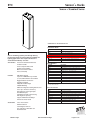
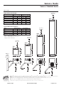
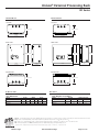
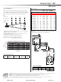
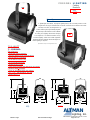
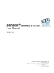
Worcester Polytechnic Institute
Lighting System Submittals
Barbizon Light of New England
Timothy Johnsen, Project Manager
3 Draper Street
Woburn MA 01801
800-935-3920 Phone extension 233
781-935-9273 FAX
[email protected]
Worcester Polytechnic Institute ~ Dimming and Distrubution Package
SUBMITTAL DATA SHEETS - TABLE OF CONTENTS
Page
Qty
Description
Section I - Dimming System
1
Dimmer enclosure for 48 modules - Designed for 3 phase, 4 wire and ground operation at a
3-6
maximum of 800A, 120/208V
36
Dual
20A Dimmer Module (72 "stage" dimmers)
7-8
2
Dual 20A Dimmer Module (4 "house" dimmers)
7-8
10
Air Flow Module
N/A
1
Control Electronics Module (CEM+)
9 - 12
Section II - Control System
1
ETC Express 125 Channel Control console
13 - 16
14" Flat Screen LCD Monitor
N/A
1
5' DMX Control Cable (M-F 5-pin XLR)
N/A
1
25' DMX Control Cable (M-F 5-pin XLR)
N/A
Control Wire
250'
Belden 9729 (DMX Control Wire)
17 - 20
500'
Belden 6200FE (Architectural Control Wire)
21 - 23
20'
Belden 1583A (Network Control Wire)
24 - 27
Section III - Architectural Controls
ETC Unison External Processing Rack w/ CME Control Module
28 - 31
2
Air flow module
N/A
2
ETC Unison Control Station with two buttons. Entry / Panic Station - - 1 @ Main Entry
32 - 33
Door, 1 @ Steps
1
ETC Unison Control Station with 10 -preset buttons. "Master Station" w/ record - - Control
Booth
Section IV - Power Distribution
12
Pipe Mounted Outlet Box with 6- 2P&G outlets, wired up to 6-20A circuits
34
NOTE: Plugging boxes will be labeled sequentially "1" through "72" and furnished with UBolt kit oriented to mount above the pipe grid. Grid placement by owner.
Section V - Fixtures and Accessories
35 - 36
o
20
ETC 36 Source Four Ellipsoidal with c-clamp, color frame, safety cable , 575 Watt lamp and
20A 2P&G connector.
ETC 50o Source Four Ellipsoidal with c-clamp, color frame, safety cable. 575 Watt lamp and
20A 2P&G connector.
Altman 6" Fresnel with c-clamp, color frame, safety cable, 750 watt lamp and 20A 2P&G
30
39 - 40
connector.
10
City
Theatrical B-size Pattern Holder - Sandwich Style for Source 4
41
Section VI - Pipe Grid Materials
1239
N/A
1.5" Schedule 40 pipe - 59 -21' lengthes, cleaned and primed
34
N/A
34 - spice pipes, cut to 18" length
15
42
Wall Flange
90
43
Over-Lap Bracket
37 - 38
40
ETC
Sensor + Racks
®
Sensor+ Standard Series
O R D E R I N G I N F O R M AT I O N
Installation Racks
Model#
Sensor+ dimming systems provide high density,
professional features and exceptional reliability for
lighting applications that require the best the
entertainment industry can offer.
SR6+
SR12+
SR24+
SR48+
SR6+1P
SR12+1P
SR24+1P
APPLICATIONS
Rack Options*
G E N E R A L I N F O R M AT I O N
Professional and educational theatre
Production studios
Model#
Concert and performance halls
AT12
AT24
AT48
BK12
BK24
BK48
AUX19-12
AUX19-24
Themed retail and dining
Multi-use Convention Centers
Houses of Worship
FEATURES
High dimmer density
Up to two 2.4kW dimmers per module
AUX12-48
AUX19-48
AUX30-48
6, 12, 24, and 48 module racks available
Rugged industrial construction
Installation flexibility
Advanced configuration editing built into rack
Model#
SBOX
Two DMX512 inputs
DD
DD-B
DD-C
All racks UL and cUL Listed
ACCESSORIES
Rack Accessories
Direct Ethernet control signal input
Supports ETC Dimmer Doubling™
Description
Amp-Trap® fuse option for 12-module rack
Amp-Trap® fuse option for 24-module rack
Amp-Trap® fuse option for 48-module rack
Bussing kit for 2 - 12-module racks
Bussing kit for 2 - 24-module racks
Bussing kit for 2 - 48-module racks
19" Auxiliary Rack(s) for 12-module rack
19" Auxiliary Rack(s) for 24-module rack
12" Auxiliary Rack(s) for 48-module rack
19" Auxiliary Rack(s) for 48-module rack
30" Auxiliary Rack(s) for 48-module rack
Contact ETC for details
100,000 AIC Rating
Standard system and rack monitoring
with diagnostic reporting
6 Module Rack
12 Module Rack
24 Module Rack
48 Module Rack
6 Module Single Phase Rack
12 Module Single Phase Rack
24 Module Single Phase Rack
*Vibration Reduction mounts available for all Sensor+ rack.
Adaptable modular design
Stores up to 128 Presets in memory
Description
Sensor+
Sensor+
Sensor+
Sensor+
Sensor+
Sensor+
Sensor+
SSSh 6-12
SSSh 24-48
Pedestal
DH
Description
Sensor+ Preset Station
Dimmer Doubler without input connector
Dimmer Doubler with Stage Pin input connector
Dimmer Doubler with Twist-loc® input connector
Sensor+ Sound Suppression Hood - small
Sensor+ Sound Suppression Hood - large
Floor pedestal for 24-module rack
Document holder
Sensor Preset Station
Dimmer Doubler™
Sound Suppression Hood
Floor pedestal for 24-module rack
Document holder
Barbizon Light
WPI Submittal Package
Page 3 of 43
O R D E R I N G I N F O R M AT I O N
S P E C I F I C AT I O N S
GENERAL
Racks available in four sizes
SR6+
SR12+
SR24+
SR48+
Dimmer Modules
6 modules, 12 dimmers maximum
12 modules, 24 dimmers maximum
24 modules, 48 dimmers maximum
48 modules, 96 dimmers maximum
Model#
D15
D20
D15E
D20E
D50AF
Dual density (two dimmers per module),
single density and half density
dimmer modules available
Operating temperature: 0-40°C / 32-104°F
Dimmer room HVAC systems must at all times maintain the
specified ambient temperature at the dimmer rack. Dimming
systems operating within 10 degrees F of the upper or lower
temperature limits must strictly follow installation and
operation guidelines to operate reliably.
Relative humidity: 30-90% non-condensing
All racks UL and cUL Listed
MECHANICAL
Description
Standard Sensor Modules
Rugged 16-gauge steel construction
Fine-textured, scratch-resistant, epoxy paint
SR6+ and SR12+ uses wall mount installation
SR24+ can be wall or pedestal mounted
SR48+ is floor mounted
D100AF*
Special Purpose Sensor Modules
L10
L10F
D15F
D20F
R15AF
R20AF
CC15
CC20
AFM
* Half-density modules use
Top and bottom conduit access through
removable panels (SR48+) or knockouts
(SR6+, SR12+, and SR24+)
Control Modules
No tools required for module removal or installation
CEM+
Model#
Keyed module slots prevent insertion of
inappropriate module types
Dual 15A Dimmer Module - 350µS
Dual 20A Dimmer Module - 350µS
Dual 15A Dimmer Module - 500µS
Dual 20A Dimmer Module - 500µS
Single 50A Dimmer Module - 500µS
- Advanced Features
Half 100A Dimmer Module - 500µS
- Advanced Features
Dual 10A Low Wattage Dimmer Module
Single 10A Low Wattage Fluorescent Dimmer Module
Single 15A Fluorescent Dimmer Module
Single 20A Fluorescent Dimmer Module
Dual 15A Relay Module - Advanced Features
Dual 20A Relay Module - Advanced Features
Dual 15A Constant Circuit Breaker Module
Dual 20A Constant Circuit Breaker Module
Air Flow Module
two module slots
Description
Control Electronics Module +
WIRING CHARTS
Front access to all wiring and terminations
Load Wiring Lug Capacity
Full height locking door
Electrostatic air filter easily removed from door
for periodic cleaning
High efficiency cooling system with airflow sensor
Connection
10A, 15A, 20A, and 50A lugs
100A lugs
Wire Size
4 AWG Max. (16mm2)
2/0 Max.
High visibility LED status beacon
Primary Feed Lug Capacity
ELECTRICAL
SR6+, SR12+ and SR24+ accept:
Three phase 120/208 VAC
Single phase 120/240 VAC
Connection
SR6+
SR12+
SR24+
SR48+
SR48+ accepts
Three phase 120/208 VAC
Line feed frequencies from 47-63Hz
Wire Size
Single 2/0 - 14 AWG
Dual 250 kcmil – 6 AWG
Dual 350 kcmil – 4 AWG
Dual 600 kcmil – 2 AWG
Line feed voltage range is 90-140 VAC
Load terminals accept up to #4 AWG (16mm2 )
wire (see chart)
Installation Rack dimensions
100,000 AIC rack rating
Model
Auxiliary Equipment Racks and custom
switchgear/distribution available
(Call ETC for details)
CONTROL
Sensor+ Control Electronics Module (CEM+)
ELECTRONICS
Single Ethernet control signal input
RACK DIMENSIONS
SR6+
SR12+
SR24+
SR48+
Height
inches
16.4
25.8
45.8
83.1
cm
42
66
116
211
Width
inches
14.6
14.6
14.6
14.6
Depth
cm
37
37
37
37
inches
13.3
13.3
16.8
22.8
cm
34
34
43
58
Two DMX512 inputs
Standard diagnostic reporting
Supports Dimmer Doubling™
OPTIONS
Advanced Features™ dimmer-specific load and
diagnostic reporting
Amp-Trap® fuses to allow feeding individual racks
from oversize mains
All-copper bus kits available
Auxiliary Racks
Vibration reduction kits available for all racks
Barbizon Light
WPI Submittal Package
Page 4 of 43
Sensor+ Racks
®
Sensor+ Standard Series
TYPICAL DMX SYSTEM RISER DIAGRAM
DMX Plug-in
DMX Plug-in
DMX
Booth
DMX
Stage
Express Console
Sensor+ Dimming System
TYPICAL NETWORK SYSTEM RISER DIAGRAM
ETCNet2
PC for Sensor+ Connect
and additional ETC Software
Switch
ETCNet2
ETCNet2
ETCNet2
Emph
Facepanel
CRT#1
Emphasis Server
ETCNet2
ON
RFU
Emph
Facepanel
CRT#2
KEYBOARD
OFF
Video Node
Remote Focus Unit
DMX
ETCNet2
Expression ECS Facepanel
DMX Node
Barbizon Light
WPI Submittal Package
To moving lights
or any
DMX device
Sensor+ Dimming System
Page 5 of 43
Sensor+ Racks
®
Sensor+ Standard Series
PHYSICAL
Clearance
above fan
Empty Dimmer Rack Weights
Model
Weight
SR6+
SR12+
SR12+ Door*
SR24+
SR24+ Door*
SR48+
SR48+ Door*
*Rack doors ship separately
lbs
36.0
45.0
11.0
107.0
17.0
188.0
31.0
Shipping Weight
kgs
16.0
21.0
5.0
49.0
8.0
86.0
14.0
lbs
45.0
50.0
14.0
115.0
20.0
198.0
35.0
kgs
21.0
23.0
6.5
53.0
9.0
90.0
16.0
10.0"
25cm
SR48+
Installed Dimmer Rack Weights*
Model
Maximum Weight
lbs
kgs
SR6+
71.0
33.0
SR12+
115.0
53.0
SR24+
261.0
119.0
SR48+
493.0
224.0
*Maximum — D20DHR modules (5.7lbs/slot)
Typical — D20 modules (5lbs/slot)
Refer to module datasheets to calculate rack
weight for other module types
Clearance
above fan
Typical Weight
lbs
66.0
105.0
244.0
459.0
kgs
30.0
48.0
111.0
209.0
10.0"
25cm
SR24+
Clearance
above fan
83.1"
211cm
10.0"
25cm
Clearance
above fan
45.8"
116cm
SR12+
10.0"
25cm
SR6+
25.8"
66cm
16.4"
42cm
Wall or
other
barrier
(all racks)
14.6"
37cm
14.6"
37cm
13.3"
34cm
6"
15cm
14.6"
37cm
13.3"
34cm
14.6"
37cm
16.8"
43cm
22.8"
58cm
17"
46cm
6"
15cm
17"
46cm
6"
15cm
17"
46cm
6"
15cm
Americas
■
Europe
Unit 5, Victoria Industrial Estate, Victoria Road, London W3 6UU, UK ■ Tel: +44 (0)20 8896 1000 ■ Fax: +44 (0)20 8896 2000
Asia
■
■
3030 Laura Lane, P.O. Box 620979, Middleton, WI 53562-0979 USA
■
17"
46cm
Tel: +1 608 831 4116 ■ Fax: +1 608 836 1736 ■ Toll free: 800 688 4116 ■ Toll free fax: 800 555 8912
Room 605-606, Tower III Enterprise Square, 9 Sheung Yuet Road, Kowloon Bay, Kowloon, Hong Kong ■ Tel: +852 2799 1220 ■ Fax: +852 2799 9325
Web: www.etcconnect.com
■
Email: (US) [email protected] ■ (UK) [email protected] ■ (Asia) [email protected]
Copyright © 2003 ETC. All Rights Reserved. All product information and specifications subject to change. 7151L1001 Rev. A Printed in USA 10/03
Barbizon Light
WPI Submittal Package
Page 6 of 43
15-20 Amp Dimmer Modules
ELECTRONIC THEATRE CONTROLS
Standard Dimmer Series
G E N E R A L I N F O R M AT I O N
O R D E R I N G I N F O R M AT I O N
D15 and D20 modules provide cost-effective digital phase angle
dimming for standard incandescent fixtures.
APPLICATIONS
FEATURES
Standard Sensor Dimmer Modules
All Sensor® Installation Racks (except Delta)
All Sensor Touring Racks
All Sensor Portable Packs
Two 1.8 or 2.4kW dimmers per module
350µS risetime toroidal filters standard version
500µS risetime toroidal filters enhanced version
Die-cast aluminum chassis
Tool-free installation and removal
Dual back-to-back SCRs for each circuit
Fully magnetic circuit breakers
100% duty cycle at full rating
Breakers will not derate over product life cycle
100k AIC rating
UL and cUL listed
Model#
Description
D15
D20
D15E
D20E
Dual
Dual
Dual
Dual
15
20
15
20
amp
amp
amp
amp
Dimmer
Dimmer
Dimmer
Dimmer
Module
Module
Module
Module
with
with
with
with
350µS
350µS
500µS
500µS
chokes
chokes
chokes
chokes
Compatible Systems
Model#
Description
Sensor Dimming Racks
SR6
SR12
SR24
SR48
6
12
24
48
slot
slot
slot
slot
Installation
Installation
Installation
Installation
Rack(s)
Rack(s)
Rack(s)
Rack(s)
Sensor Portable Packs
SP6
6 slot Portable Pack with MPE module
SP12
12 slot Portable Pack with MPE module
Sensor Touring Racks
SP24
24 slot Touring Rack
SP36
36 slot Touring Rack
SP48
48 slot Touring Rack
Barbizon Light
2-2.1
WPI Submittal Package
Page 7 of 43
15-20 Amp Dimmer Modules
Standard Dimmer Series
S P E C I F I C AT I O N S
PHYSICAL
DIMMER MODULES Dimmers are UL and cUL listed for continuous
Module Weights
duty at 100% of rated load
D15 – 1.8kW
D20 – 2.4kW
Dimmer modules are plug-in, and may be
replaced without tools
Cast aluminum chassis, finished with textured
epoxy paint
Includes circuit breaker(s), toroidal filter(s),
SCR modules, power and control connectors
Keyed to prevent insertion in
inappropriately rated rack positions
CIRCUIT BREAKERS Fully magnetic to eliminate nuisance tripping
20x inrush current rating
125%, 10-120 seconds, must- trip rating
Rated for 100% switching duty applications
SCR ASSEMBLY
Sealed, patented assembly
Field replaceable with screwdriver
Two back-to-back SCRs per circuit
One Control LED per circuit
4000V isolation between control and
power components
Integral bonded heatsink
Integral temperature sensor
CHOKES
High quality 350µS, risetime* toroidal filters
500µS risetime* filters in the Enhanced version
ELECTRICAL
100k AIC rating
RATINGS
Hot-patching: dimmers shall withstand hotpatching of cold incandescent loads up to the
dimmer's full rating, without tripping
Rated for continuous operation at full load
Model#
Weight
lbs
5
5
D15/20
D15E/D20E
Shipping Weight
kgs
2.3
2.3
lbs
6.9
6.9
kgs
3.1
3.1
Maximum BTU Production per module
Model#
D15
D20
D15E
D20E
BTUs
Watts
Efficiency
380
522
474
810
112
154
140
238
96.9%
96.8%
96.1%
95.0%
These values should be provided to a qualified HVAC design engineer, along
with dimmer quantities, types and dimmer room dimensions, to calculate
dimmer room air handling requirements.
Dimmer room HVAC systems must at all times maintain the specified ambient
temperature at the dimmer rack. Dimming systems operating within 10°F of
the upper or lower temperature limits must strictly follow installation and
operation guidelines to operate reliably.
SCR Rating
Module
Single cycle peak surge current
Half cycle peak surge current
Transient over voltage
15/20 amp
625 amp
1620 amp
600V
*Risetime measured at full load, at worst case firing angle
(about 50%), from 10-90% of output wave form
Electronic Theatre Controls
International • 3030 Laura Lane, P.O. Box 620979, Middleton, WI 53562-0979 • Tel: (+1) 608 831 4116 • Fax: (+1) 608 836 1736 • Toll free: 800 688 4116 • Toll free fax: 800 555 8912
Europe • 5 Victoria Industrial Estate, Victoria Road, London W3 6UU • Tel: +44 (0)20 8896 1000 • Fax: +44 (0)20 8896 2000
Asia • Room 605-606, Tower III Enterprise Square • 9 Sheung Yuet Road, Kowloon Bay • Kowloon, Hong Kong • Tel: (+852) 2799 1220 • Fax: (+852) 2799 9325
Web: www.etcconnect.com • Email: [email protected] Copyright © 2001 Electronic Theatre Controls, Inc., All Rights Reserved. All product information and specifications subject to change.
Sensor ® products protected by U.S. Patent Numbers: 5,323,088, 5,352,958, and 6,002,563 European Number: 0603333 German Number: 69203609, US and International Patents Pending
7050L1028
Barbizon Light
2-2.2
WPI Submittal Package
0601US • Rev. B
Page 8 of 43
ETC
CEM+ Control Module
Sensor®+ Series
G E N E R A L I N F O R M AT I O N
O R D E R I N G I N F O R M AT I O N
The Sensor+ Control Electronics Module (CEM+) receives
and manages Ethernet control signals as well as two
DMX512 inputs. It controls dimmer output, and
communicates feedback information to compatible
lighting control devices and network peripherals.
APPLICATIONS
FEATURES
ACCESSORIES
Professional and educational theatre
Production studios
Performance halls
Retail and dining
Houses of worship
High density architectural dimming
Touring and Portable dimming
Direct Ethernet connectivity for dimmer levels,
feedback and system control
Two DMX512 input connections
Rugged industrial construction
Modular design
Local Menu-driven User Interface
Advanced configuration editing
128 Presets with programmable fade times
System and rack feedback standard
Support for Advanced Features (AF)
dimmer-specific reporting
Supports ETC Dimmer Doubling™
UL and cUL LISTED and CE Marked
Sensor+ Connect – a browser-based
Graphical User Interface - accessible thru an
Emphasis server, computer, or a PDA
on the network
Sensor+ Preset Stations
Retrofit kits to upgrade existing Sensor racks
to CEM+ modules
Barbizon Light
Control Modules
Sensor+ Control Electronics Module
Model#
Description
CEM+
Control Electronics Module
Compatible Systems
Sensor+ Installation Racks
Model#
Description
SR6+
SR12+
SR24+
SR48+
SR6AF+
SR12AF+
SR24AF+
SR48AF+
HSR+/HSRAF+
SRAFN+
SRD2+
ESRAFN+
Sensor+ Touring Racks
Model#
SP4820+
SP7220+
SP9620+
Accessories
Model#
SBOX
RK
RK-AF
WPI Submittal Package
Sensor+ 6 module rack
Sensor+ 12 module rack
Sensor+ 24 module rack
Sensor+ 48 module rack
Sensor+ 6 module Advanced Features rack
Sensor+ 12 module Advanced Features rack
Sensor+ 24 module Advanced Features rack
Sensor+ 48 module Advanced Features rack
Sensor+ 230V racks
Sensor GFCI racks
Sensor Delta racks
Sensor CE racks
Description
Sensor+ 24 module Touring Rack
(48- 20A dimmers)
Sensor+ 36 module Touring Rack
(72- 20A dimmers)
Sensor+ 48 module Touring Rack
(96- 20A dimmers)
Description
Sensor+ Preset Stations
CEM to CEM+ Retrofit kit for standard
Sensor racks
CEM to CEM+ Retrofit kit for Sensor AF racks
Page 9 of 43
S P E C I F I C AT I O N S
GENERAL
PHYSICAL
ELECTRICAL
CONTROL
FEATURES
FEEDBACK
LOCAL PROGRAMMING MENU
Universal Control Electronics Module
Direct Ethernet connectivity for dimmer levels,
feedback and system control
UL, cUL LISTED and CE Marked
Formed steel body finished with textured
epoxy paint
Injection molded face panel
Slide-in module installs and removes without tools
Spring-loaded module release
Airflow sensor to ensure adequate airflow
Accepts:
Single phase
Three phase WYE or Delta
Universal Voltage range 90-250 VAC
Line feed frequencies from 47-63Hz
Automatic frequency variation compensation
2-line by 20-character backlit LCD for system
configuration, status display and error indication
Backlit 7-button keypad includes Reset button
4 status LED indicators: Power, Network activity,
DMX-A and DMX-B
Two configurable DMX512 inputs
(2500V opto-isolated)
128 user-programmable presets assignable
to 4 rooms
Maximum of 1024 racks (64 groups of 16)
Single Panic circuit with flexible programming
Complete group configuration stored in each CEM+
Individual CEM+ failure does not disable
multi-rack group
Replacement CEM+ can download configuration
from adjacent racks, rack back plane or online server
Multi-rack configuration can be restored from
a single CEM+
Dimmer outputs are regulated to
maintain constant power to loads ± 1V
Individual output scale voltage settings for load
wiring compensation (60 – 140V)
Selectable Dimmer Modes
Normal
Dimmer Doubled
Switched (unregulated on/off
with adjustable threshold)
Fluorescent with adjustable threshold
Always On
Off
Selectable Dimmer Output Curves
Linear
Modified Linear
Square
Modified Square
Sensor 2.0
40,000-Step Resolution per half cycle
Response speed <25mS
Selectable Data Loss Behavior
All Sensor racks with CEM+s include basic system
diagnostic reporting
Remote monitoring, programming and backup
functions over the network using Sensor+
Connect or WYSILink software program
Standard rack feedback includes: DMX input
status, Rack power status, and Rack temperature
Advanced Features (AF) provides dimmer specific
status and load feedback (requires AF dimmer
rack and AF dimmer modules)
Barbizon Light
RACK ERRORS
ABOUT
LOGIN
PRESETS
PANIC
DIMMERS
RACK
SETUP
GROUP
SETUP
WPI Submittal Package
View Error messages
About Group: Software version, panic status,
preset status, and group name
About Network: IP address, SubNet mask
and Gateway
About Rack General: ambient temperature
and airflow, rack type, and air filter status
About Rack Power: frequency, voltage per
phase, and voltage headroom
About Rack Data: status for DMXA, DMXB,
and Network activity
About Rack Address: DMXA, DMXB or
EDMX start address, Rack Address mode
(Standard or Advanced)
About Dimmer: module type, curve,
scale voltage, output level, control source,
and module location
About Room: assign and monitor presets
in a room
Identify Rack: quick way to find and identify a
single rack in a group
Security Level passwords determine screens
and modes available to user
Play, deactivate or clear presets
Record presets from DMX, EDMX and set levels
Set fade times and priority levels
Name presets and rooms
Set maximum number of active presets per room
Activate, deactivate or clear group-wide panic
Record panic from DMX, EDMX and set levels
Record panic properties: normally open or closed,
maintained or momentary, master level,
and option to force all non-panic dimmers
to zero
Set dimmers at levels and release
Set dimmer curve
Name the dimmer
Name rack and set type of rack
Patch Capability
Set first dimmer and address mode
(standard or advanced)
Set Temperature Alarm
Set Power Balance – Column, Single Phase or
Three Phase
Set Air Filter Cleaning reminder based on hours
of use
Configure Fan as Always On or Off if no
data/15 min.
Select Data loss Behavior – Hold last Look, Wait
and fade, Crossfade to a Preset
Name Group
Setup Group Network – IP Address,
SubNet mask, Gateway Address and
Enable/Disable Network
Set Data Priority per DMX port
Select Language – English, French, Spanish
or German
Select Temperature Reporting type - F° or C°
Set Login Timeout
Record Loads and Report Load Errors
Page 10 of 43
CEM+ Control Module
Sensor®+ Series
DIMENSIONS
TOP VIEW
7.00"
178mm
FRONT VIEW
11.80"
300mm
SIDE VIEW
2.06"
52mm
Control Electronic Module Weight
Model
Maximum BTU Production per module
Weight
lbs
4.2
CEM+
Shipping Weight
kgs
2
lbs
6.2
kgs
2.8
Model
BTUs
Watts
ALL CEM+
<10
<4
Efficiency
N/A
TYPICAL NETWORK SYSTEM RISER DIAGRAM
Link Power
Aux Power
ETCNet2
Unison Control Stations
PC for ETC software
Link Power
Emphasis
WRFU
(Wireless)
CMEi in
ER4 Rack
Hub/Switch
ETCNet2
ETCNet2
ETCNet2
ETCNet2
Emph
Facepanel
CRT#1
Emphasis Server
Emph
Facepanel
CRT#2
ETCNet2
ON
RFU
KEYBOARD
OFF
Video Node
Remote Focus Unit
ETCNet2
Expression ECS Facepanel
DMX from
external source
DMX
DMX Node
ETCNet2
DMX Node
with ports set
for input
Barbizon Light
ETCNet2
Wireless Access Point
WPI Submittal Package
Remote Focus Unit
To moving lights
or any
DMX device
Sensor+ Dimming System
Page 11 of 43
CEM+ Control Module
Sensor®+ Series
SENSOR+ CONNECT
DIMMER
Set dimmer name and module type
CONFIGURATION Set dimmer mode: Normal, Dimmer Doubled
Sensor+ Connect duplicates the functions of the Control
Electronics Module (CEM+), but on your Emphasis server,
computer or even your PDA. This graphical user interface
(GUI) allows you to monitor rack activity, reconfigure
dimmer curves, record or activate presets – plus a whole
lot more.
Offers all the features needed to create, edit and download
specific information to the racks and modules.
FEATURES
Configure rack and module information
Patch/Address 2 DMX Universes
File transfer capabilities
Record and activate 128 preset looks
Assign presets to up to 4 rooms
SYSTEM
Emphasis server, Computer or PDA
REQUIREMENTS Internet Browser Software such as
Internet Explorer 6.0 or better
Network connection (wired or wireless) to
a Sensor System with a CEM+ module
PRESETS
PHYSICAL
CONFIG
B R O W S E R N AV I G AT I O N
LOGIN
HOME
RACKS
Security Level passwords determine screens
and modes available to user
System Summary – Rack status, Active Presets,
Error List
Select a rack or all racks
View rack status, rack configurations, dimmer
configuration and rack specific errors
Rack Configuration
Name rack and set type of rack
Set Address mode: standard or advanced
Set Temperature Alarm
Select Power Balance – Column, Single
Phase or Three Phase
Configure Fan Time mode as Always On or
Off if no data/15 min.
Dimmer Search
Search for dimmer(s) by specifying a number
of search criteria – quick dimmer configuration
DIAGNOSTICS
Americas
■
Europe
Unit 5, Victoria Industrial Estate, Victoria Road, London W3 6UU, UK ■ Tel: +44 (0)20 8896 1000 ■ Fax: +44 (0)20 8896 2000
Asia
■
■
3030 Laura Lane, P.O. Box 620979, Middleton, WI 53562-0979 USA
Switched, Fluorescent, Always On, Off
Set dimmer curve: Linear, Modified Linear,
Square, Modified Square and Sensor 2.0
Set Scale Voltage and Threshold levels
Select On/Off for Voltage Regulation, Preheat,
DC Output Prevention, and Inrush Protection
Set Temperature Reporting mode as F° or C°
Assign Dimmers:
Assign dimmers to Rooms
Room 1, 2, 3 or 4:
Play or deactivate presets
Record presets from DMX, EDMX and Set levels
Set fade times and priority levels
Set Room Properties – name and maximum
number of active presets
Panic
Play or deactivate group-wide panic
Record and clear panic
Set panic properties: normally open or closed,
maintained or momentary, master level, and
option to force all non-panic dimmers to zero
Patch
Patch Configuration includes: Port
Enable, DMX Loss Behavior, Dimmer Number
Start, Length, Priority, Fade and Hold Time.
Network
Setup Group Network – IP Address, Netmask,
Gateway Address and Enable/Disable Network
File Transfer
Copy configuration files to a computer
(download)
Send updated configuration files to
CEM+ (upload)
Load Management
Record Loads and Report Load Errors
Dimmer Check
Set a dimmer to a level, with easy
dimmer advancement
Dimmer Level
Set dimmer(s) to a specified intensity.
■
Tel: +1 608 831 4116 ■ Fax: +1 608 836 1736 ■ Toll free: 800 688 4116 ■ Toll free fax: 800 555 8912
Room 605-606, Tower III Enterprise Square, 9 Sheung Yuet Road, Kowloon Bay, Kowloon, Hong Kong ■ Tel: +852 2799 1220 ■ Fax: +852 2799 9325
Web: www.etcconnect.com
■
Email: (US) [email protected] ■ (UK) [email protected] ■ (Asia) [email protected]
Copyright © 2003 ETC. All Rights Reserved. All product information and specifications subject to change. 7150L1001 Rev. A Printed in USA 11/03
Barbizon Light
WPI Submittal Package
Page 12 of 43
Express™ 125 & 250
ELECTRONIC THEATRE CONTROLS
PUSH
PUSH
Express Console Series
Submasters
1
2
3
4
5
6
7
10
9
8
7
6
5
4
3
2
1
0
10
9
8
7
6
5
4
3
2
1
0
10
9
8
7
6
5
4
3
2
1
0
10
9
8
7
6
5
4
3
2
1
0
10
9
8
7
6
5
4
3
2
1
0
10
9
8
7
6
5
4
3
2
1
0
8
9
10
11
12
Master
10
9
8
7
6
5
4
3
2
1
0
13
10
9
8
7
6
5
4
3
2
1
0
10
9
8
7
6
5
4
3
2
1
0
14
15
16
17
10
9
8
7
6
5
4
3
2
1
0
10
9
8
7
6
5
4
3
2
1
0
18
19
20
21
10
9
8
7
6
5
4
3
2
1
0
22
23
24
10
9
8
7
6
5
4
3
2
1
0
A
B
C
10
9
8
7
6
5
4
3
2
1
0
D
10
9
8
7
6
5
4
3
2
1
0
G E N E R A L I N F O R M AT I O N
O R D E R I N G I N F O R M AT I O N
Foundational lighting control console with preset-style operation,
Expression 3 compatibility, 125 or 250 channels.
APPLICATIONS College
Middle/ High School
Community Theatre
Trade Show
Small TV Studio
Church
FEATURES
Preset style operation
125 or 250 channels
1024 DMX outputs
600 Cues
500 Groups
2000 Macros
10 pages of 24 Submasters
Two scene preset or preprogrammed operation
Preset Focus points
Moving Light controls
LTP (Latest Takes Precedence) Channels
Spreadsheet Editing
Ethernet for DMX, Video and other
signal distribution
MIDI, MIDI Show Control and MIDI Time
Code interface
Supports ETCLink Dimmer feedback
ACCESSORIES
Video Node
DMX Node
Remote Focus Unit (RFU)
Gooseneck Lamps
Expression Offline
Expression Offline for Windows
Express LPC
Express
Model#
Description
EXPS 125
Express 125
EXPS 250
Express 250
LPC/250
Express 250 Channel LPC
Express Accessories
Model#
Description
DNODE-RF
DMX Node - rack mount front entry
DNODE-RB
DMX Node - rack mount rear entry
DNODE-W
DMX Node - wallbox mount
VNODE-R
RFU
M218
M219
4000A4003
M715
M604
EOL
Video Node
Remote Focus Unit
VGA Color Monitor
LCD Flat Screen Display
Monitor Dust Cover for M218
Littlelite Work Light
Parallel Printer
Expression Offline
Other Consoles in Express Family
Model#
Description
EXPS 24/48
Express 24/48
EXPS 48/96
Express 48/96
EXPS 72/144
Express 72/144
LPC/96
Express 96 Channel LPC
LPC/192
Express 192 Channel LPC
1-5.1
Barbizon Light
WPI Submittal Package
Page 13 of 43
S P E C I F I C AT I O N S
125 or 250 channels
1,024 DMX512 dimmers
600 cues
500 groups
99 focus points
Effects with up to 100 steps each
2,000 macros
24 submasters x 10 pages
2 timed/manual fader pairs
Diskette drive
Single VGA output
Printer port
UL, cUL, CE listed
DISPLAY FUNCTIONS
(Requires VGA monitor)
Cue List
Stage
Blind
Fader status
Spreadsheets and Lists
Cue, Sub, Group and Focus point views
Patch
Proportional levels
32 user–definable profiles
Dimmer Doubling capability (see Dimmer
Doubling data sheet)
Setup
Flexichannel (displays only used channels)
PLAYBACK CONTROLS Faders
2 Timed/manual fader pairs with Go, Hold,
Rate, Clear, and Back buttons
Individual last action fade capability for every
channel
Trackpad
Master slider
Blackout button
Submasters
24 submasters (times 10 pages) with bump
buttons and integral LEDs
OPTIONAL EQUIPMENT DMX Node
ETCNet 2 device with remote DMX
output, RFU
Video Node
ETCNet 2 device with keyboard, RFU, VGA,
Printer ports, Serial
Remote Focus Unit
Hand held device with a keypad and LCD
screen accesses most system functions for
local adjustments and show editing
Expression Off-Line
Available for free download from ETC via
www.etcconnect.com
Parallel Printer
VGA Monitor
INTERFACES
DMX512 Outputs (2)
Ethernet
ETCLink
MIDI
MIDI Show Control
MIDI Time Code
Remote Macro/Go
Remote Trigger
Remote Focus Unit (RFU)
GENERAL
Barbizon Light
CONTROL KEYPAD
FEATURES
1-5.2
WPI Submittal
Package
Cue attributes
Cues from .1 to 999.9
Split up/down fade times
Wait times
Follow time
Link to cue or macro
Modified rate
8-part multipart cues
Selective cue recording
Channel Functions
Lists constructed with +, –, Except, And, Thru
Sneak sets channel to discrete or fader level in
default/specified time.
Only and Except features for group and channel
manipulation.
Channel Attribute Display
Independent channel capability
Last Action Channels
X/Y Link List
Moving Light Functions
100 Focus point
16–bit fade resolution
Pop–up displays
ML Patch
Group Functions
500 groups with labels
Any cue or submaster may be accessed as
a group
Submaster Functions
10 pages of 24 submasters with labels, timing
and rate attributes
Bump buttons may be enabled, disabled or solo
Range editing of submaster attributes in
submaster list
Submasters may be individually changed
between pile-on and inhibitive
Effect Functions
100 steps each
Step times
In/Dwell/Out step times
High/Low levels
In/Dwell/Out effect times
Effects may be recorded as cues and loaded
to submasters.
Range editing of effect step values
and attributes
Live effects recording
Macros
2,000 macros
Macros may activate any button on the console
Live Learn mode
Blind editing
Astronomical Time Clock
Program up to 500 events
Play back according, day of week, time of
day or in reference to time before/after sunrise
or sunset
Page 14 of 43
Express™ 125 & 250
Express Console Series
CONSOLE CONNECTIONS
Sensor Dimming Rack
B
DMX
B
DMX to Scrollers or Moving Lights
C
ETCLink
Cue
1
2
1
M1
A/B
Clear
Stage
Chan
5 at 75
Blind
7
8
D
Remote Focus Unit
Stage
9
6
Chan
Thru
Dim
M*
S*
4
5
Sub
Group
1
2
3
And
A/B
Hold
Time
Cue
–
0
+
Except
Level
A/B
Go
Track
Rec
Clear
•
Enter
Rec
Solo
A/B
Back
At
Full
Remote Focus Unit
Lamps 12V
Ext. 12V
RFU
F 1.5A
5 x 20mm
DMX512
PUSH
1 - 512
PUSH
ETCLink
513 - 1024
PUSH
PUSH
Electronic Theatre Controls, Inc.
3030 Laura Lane, Middleton, Wisconsin 53562-1754
Product:
Model #:
Serial #:
Manufactured By
Power Input
CRT Display
Parallel Printer
Remote Macro
5V @ 3A / 12V @ 2A
Electronic Theatre Controls, Inc.
Middleton, WI USA
110-240 VAC
MIDI
In
ETCNet
Out
Thru
Twisted Pair
ThinNet
ETCNET2 DMX NODe
PSU
50/60 HZ
Power
DMX Input / Output
Reset
1
(Power Supply Unit)
2
3
PUSH E T C
PUSH R f u
PUSH D M X
PUSH D M X
link
PUSH D M X
Network
Activity
4
1
2
3
DMX Node
PUSH D M X
4
A
Monitor
Ethernet*
G
PUSH D M X
Printer
1
PUSH D M X
2
PUSH D M X
PUSH D M X
3
4
PUSH E T C
link
PUSH R f u
ETCNET2 DMX NODe
Power
DMX Input / Output
Reset
1
2
3
4
DMX Node
H
Remote Macro
PUSH
*Ethernet distribution equipment required
E
MIDI In/Out/Thru
Video Node and Monitor
Wire Types for Express consoles with....
Device
Wire Type
DMX (XLR5)
(1) Belden 9729
ETCLink (XLR6)
(1) Belden 9729
(2) #16 AWG Stranded
B
Device
Wire Type
MIDI
Standard MIDI Cables
5 Pin Din Connector
E
RFU (XLR6)
(1) Belden 9728
(2) #16 AWG Stranded
D
DMX (In + Out)
DMX (XLR5)
Belden 9729
B
C
Cue
1
2
1
Chan
5 at 75
Stage
Blind
7
8
9
M*
S*
4
5
6
A/B
Back
Sub
Group
1
2
3
And
Full
A/B
Hold
Time
Cue
–
0
+
Except
Level
A/B
Go
Track
Rec
Clear
•
Enter
Rec
Solo
M1
A/B
Clear
Stage
Chan
Thru
Dim
At
Remote Focus Unit
Sensor Racks
Remote Focus Unit
PUSH
Video Node
PUSH D M X
1
PUSH D M X
2
PUSH D M X
3
PUSH D M X
4
PUSH E T C
link
PUSH R f u
ETCNET2 DMX NODe
Power
DMX Input / Output
Reset
1
2
3
4
Network
Activity
DMX Node rack mount
Category 5 Ethernet (RJ45)
(1) Belden 1583A (UTP)
A
Category 5 Ethernet (RJ45)
(1) Belden 1583A (UTP)
A
Printer - Parallel
Standard Parallel Printer Cable
G
A
Remote Macro
DB 15
Consult Manual or ETC Technical Services
for details
H
ETCNET2 DMX NODe
Power
DMX Input / Output
Reset
1
2
3
PUSH R f u
PUSH D M X
PUSH D M X
link
PUSH D M X
1
Network
Activity
4
PUSH E T C
2
3
PUSH D M X
4
Category 5 Ethernet (RJ45)
(1) Belden 1583 (UTP)
(2) #16 AWG Stranded
DMX Node wall mount
Barbizon Light
1-5.3
WPI Submittal
Package
Page 15 of 43
Network
Activity
Express™ 125 & 250
Express Console Series
35"
89cm
Lamps 12V
Ext. 12V
RFU
F 1.5A
5 x 20mm
6"
15cm
PUSH
DMX512
1 - 512
PUSH
ETCLink
513 - 1024
PUSH
PUSH
Electronic Theatre Controls, Inc.
3030 Laura Lane, Middleton, Wisconsin 53562-1754
Product:
Model #:
Serial #:
Manufactured By
Power Input
CRT Display
Parallel Printer
Remote Macro
5V @ 3A / 12V @ 2A
MIDI
ETCNet
Out
Thru
Twisted Pair
ThinNet
PUSH
In
PUSH
Electronic Theatre Controls, Inc.
Middleton, WI USA
Submasters
10
9
8
7
6
5
4
3
2
1
0
10
9
8
7
6
5
4
3
2
1
0
1
15"
38cm
2
3
10
9
8
7
6
5
4
3
2
1
0
4
5
10
9
8
7
6
5
4
3
2
1
0
6
7
10
9
8
7
6
5
4
3
2
1
0
8
9
10
9
8
7
6
5
4
3
2
1
0
10
11
12
Master
10
9
8
7
6
5
4
3
2
1
0
13
10
9
8
7
6
5
4
3
2
1
0
10
9
8
7
6
5
4
3
2
1
0
14
15
16
17
10
9
8
7
6
5
4
3
2
1
0
10
9
8
7
6
5
4
3
2
1
0
18
19
20
21
10
9
8
7
6
5
4
3
2
1
0
22
23
24
A
10
9
8
7
6
5
4
3
2
1
0
B
C
10
9
8
7
6
5
4
3
2
1
0
D
10
9
8
7
6
5
4
3
2
1
0
PHYSICAL
Express Weights*
Express Dimensions
Model
Height
Express 125 and 250
inches
6.0
cm
15.0
Width
inches
35.0
cm
89.0
Model
Depth
inches
15.0
cm
38.0
Express 125 and 250
Express Accessories Dimensions*
Model
Height
Express LPC
DMX Node - rack
DMX Node -wallbox
Remote Focus Unit
Video Node
inches cm
1.8
4.5
1.8
4.5
8.0
20.3
1.4
3.4
1.8
4.5
Weight
lbs
21.0
kgs
9.5
Shipping Weight
lbs
35.0
kgs
16.0
Express Accessories Weights*
Width
inches
17.0
17.0
8.0
8.5
17.0
cm
43.2
43.2
20.3
25.0
43.2
Depth
inches
12.5
12.5
4.1
5.5
12.5
Model
cm
32.0
32.0
10.5
14.0
32.0
Express LPC
DMX Node - rack
DMX Node -wallbox
Remote Focus Unit
Video Node
Weight
lbs
11.0
8.0
2.2
3.0
8.0
kgs
5.0
3.6
1.0
1.4
3.6
Shipping Weight
lbs
18.3
18.0
10.0
5.0
18.0
kgs
8.3
8.2
4.5
2.3
8.2
* Weights + Dimensions Typical
Electronic Theatre Controls
International • 3030 Laura Lane, P.O. Box 620979, Middleton, WI 53562-0979 • Tel: (+1) 608 831 4116 • Fax: (+1) 608 836 1736 • Toll free: 800 688 4116 • Toll free fax: 800 555 8912
Europe • 5 Victoria Industrial Estate, Victoria Road, London W3 6UU • Tel: +44 (0)20 8896 1000 • Fax: +44 (0)20 8896 2000
Asia • Room 605-606, Tower III Enterprise Square • 9 Sheung Yuet Road, Kowloon Bay • Kowloon, Hong Kong • Tel: (+852) 2799 1220 • Fax: (+852) 2799 9325
Web: www.etcconnect.com • Email: [email protected] Copyright © 2001 Electronic Theatre Controls, Inc., All Rights Reserved. All product information and specifications subject to change.
4110L1017
Barbizon Light
1-5.4
WPI Submittal Package
0601US • Rev. B
Page 16 of 43
9729 Paired - Low Capacitance Computer Cable for EIA RS-422 Applications
For more information please
call
1-800-Belden1
See Put-ups and Colors
Color Code Chart : No. 3 for
Paired Cables (Belden
Standard).pdf
Description:
24 AWG stranded (7x32) tinned copper conductors, twisted pairs, Datalene® insulation, individually shielded with 100% Beldfoil® shield,
24 AWG stranded tinned copper drain wire each pair, PVC jacket.
PHYSICAL CHARACTERISTICS:
CONDUCTOR:
Number of Pairs
2
Total Number of Conductors
4
AWG
24
Stranding
7x32
Conductor Diameter
.024 in.
Conductor Material
TC - Tinned Copper
INSULATION:
Insulation Material Trade Name
Datalene®
Insulation Material
FPE - Foam Polyethylene
Insulation Diameter
.061 in.
Lay Length
1.1 in.
Twists/ft.
10.9
Pair Color Code Chart :
Number
1
Color
Black & Red
Number
2
Color
Black & White
INNER SHIELD:
Inner Shield Material Trade Name
Beldfoil® (Z-Fold®)
Inner Shield Type
Tape
Inner Shield Material
Aluminum Foil-Polyester Tape
Inner Shield % Coverage
100 %
Inner Shield Drain Wire AWG
24
Inner Shield Drain Wire Stranding
7x32
Page 1 of 4
Barbizon Light
WPI Submittal Package
Page 17 of 43
9729 Paired - Low Capacitance Computer Cable for EIA RS-422 Applications
Inner Shield Drain Wire Conductor Material
TC - Tinned Copper
OUTER JACKET:
Outer Jacket Material
PVC - Polyvinyl Chloride
OVERALL NOMINAL DIAMETER:
Overall Nominal Diameter
.266 in.
MECHANICAL CHARACTERISTICS:
Operating Temperature Range
-20°C To +80°C
UL Temperature Rating
60°C (UL AWM Style 2493)
Bulk Cable Weight
34.5 lbs/1000 ft.
Max. Recommended Pulling Tension
22 lbs.
Min. Bend Radius (Install)
3.25 in.
APPLICABLE SPECIFICATIONS AND AGENCY COMPLIANCE:
APPLICABLE STANDARDS:
NEC/(UL) Specification
CM
CEC/C(UL) Specification
CM
AWM Specification
UL Style 2493 (300 V 60°C)
FLAME TEST:
UL Flame Test
UL1685 UL Loading
PLENUM/NON-PLENUM:
Plenum (Y/N)
N
Plenum Number
89729, 82729
ELECTRICAL CHARACTERISTICS:
Nom. Characteristic Impedance
100 Ohms
Nom. Inductance
0.23 µH/ft
Nom. Capacitance Conductor to Conductor @ 1 KHz
12.5 pF/ft
Nom. Cap. Cond. to Other Cond. & Shield @ 1 KHz
23.2 pF/ft
Nominal Velocity of Propagation
76 %
Nom. Conductor DC Resistance @ 20 Deg. C
24 Ohms/1000 ft
Ind. Pair Nominal Shield DC Resistance @ 20 Deg. C
15 Ohms/1000 ft
Nom. Attenuation (dB/100 ft) :
Page 2 of 4
Barbizon Light
WPI Submittal Package
Page 18 of 43
9729 Paired - Low Capacitance Computer Cable for EIA RS-422 Applications
Description
Frequency (MHz)
Start Frequency (MHz)
Stop Frequency (MHz)
.384
.7056
.768
1.024
1.4112
1.536
2.048
2.8224
3.072
4.096
5.6448
6.144
8.192
11.2896
12.288
24.576
Max. Operating Voltage - UL
300 V RMS (UL AWM Style 2493)
Max. Recommended Current
1 Amp per conductor @ 25°C
Nom. Attenuation
(dB/100 ft.)
0.74
0.87
0.88
0.94
1.01
1.03
1.13
1.29
1.35
1.57
1.78
1.84
2.13
2.45
2.57
3.57
NOTES:
Notes
Datalene® insulation features include low dielectric constant and a dissipation
factor for high-speed, low-distortion data handling. Physical properties include
good crush resistance and light weight.
PUT-UPS AND COLORS:
Item
Description
9729 060100
2 FS PR #24 FHDPE
PVC
9729 0601000
2 FS PR #24 FHDPE
PVC
9729 06010000
2 FS PR #24 FHDPE
PVC
9729 060500
2 FS PR #24 FHDPE
PVC
Put-Up (ft.)
100
Ship Weight (lbs.)
4.3
Jacket Color
CHROME
Notes
1000
39
CHROME
C
10000
390
CHROME
CY
500
20.5
CHROME
C
C = CRATE REEL PUT-UP.
Y = FINAL PUT-UP LENGTH MAY VARY -10% TO +20% FROM LENGTH SHOWN. MAY CONTAIN 2 PIECES. MINIMUM
LENGTH OF ANY ONE PIECE IS 1500'.
Revision Number: 1
Revision Date: 02-15-2005
Page 3 of 4
Barbizon Light
WPI Submittal Package
Page 19 of 43
9729 Paired - Low Capacitance Computer Cable for EIA RS-422 Applications
© 2005 Belden Wire & Cable Company
All Rights Reserved.
Although Belden Electronics Division ("Belden") makes every reasonable effort to ensure their accuracy at the time of this publication,
information and specifications described herein are subject to error or omission and to change without notice, and the listing of such
information and specifications does not ensure product availability.
Belden provides the information and specifications herein on an "AS IS" basis, with no representations or warranties, whether express,
statutory or implied. In no event will Belden be liable for any damages (including consequential, indirect, incidental, special, punitive, or
exemplary damages) whatsoever, even if Belden has been advised of the possibility of such damages, whether in an action under contract,
negligence or any other theory, arising out of or in connection with the use, or inability to use, the information or specifications described
herein.
All sales of Belden products are subject to Belden's standard terms and conditions of sale.
Page 4 of 4
Barbizon Light
WPI Submittal Package
Page 20 of 43
6200FE Non-Paired - New Generation®
For more information please
call
1-800-Belden1
See Put-ups and Colors
Description:
Bare copper conductors, Flamarrest® insulation, conductors cabled, overall Beldfoil® tape shield (aluminum side out) and drain wire,
Flamarrest® jacket with ripcord. Sequential footage marking every two feet.
SUITABLE APPLICATIONS:
Suitable Applications
Security Systems, Intercom/PA Systems, Sound/Audio Systems, Power Limited
Controls
PHYSICAL CHARACTERISTICS:
CONDUCTOR:
Number of Conductors
2
Total Number of Conductors
2
AWG
16
Stranding
19x29
Conductor Material
BC - Bare Copper
INSULATION:
Insulation Material Trade Name
Flamarrest®
Insulation Material
LS PVC - Low Smoke Polyvinylchloride
Nom. Insulation Wall Thickness
.009 in.
OVERALL CABLING:
Overall Cabling Lay Length
2 in.
Overall Cabling Twists/ft.
6.0
Overall Cabling Color Code Chart :
Number
1
Color
Black
Number
2
Color
Red
OUTER SHIELD:
Outer Shield Material Trade Name
Beldfoil®
Outer Shield Type
Tape
Outer Shield Material
Aluminum Foil-Polyester Tape w/Shorting Fold
Outer Shield %Coverage
100 %
Outer Shield Drain Wire AWG
18
Outer Shield Drain Wire Stranding
19x30
Page 1 of 3
Barbizon Light
WPI Submittal Package
Page 21 of 43
6200FE Non-Paired - New Generation®
Outer Shield Drain Wire Conductor Material
TC - Tinned Copper
OUTER JACKET:
Outer Jacket Material Trade Name
Flamarrest®
Outer Jacket Material
LS PVC - Low Smoke Polyvinyl Chloride
Outer Jacket Nominal Wall Thickness
.015 in.
Outer Jacket Ripcord
Yes
OVERALL NOMINAL DIAMETER:
Overall Nominal Diameter
.184 in.
MECHANICAL CHARACTERISTICS:
Operating Temperature Range
0°C To +75°C
UL Temperature Rating
75°C
Bulk Cable Weight
31 lbs/1000 ft.
Max. Recommended Pulling Tension
85.5 lbs.
Min. Bend Radius (Install)
1.9 in.
APPLICABLE SPECIFICATIONS AND AGENCY COMPLIANCE:
APPLICABLE STANDARDS:
NEC/(UL) Specification
CMP
NEC Articles
800
CEC/C(UL) Specification
CMP
FLAME TEST:
UL Flame Test
NFPA 262
C(UL) Flame Test
FT6
PLENUM/NON-PLENUM:
Plenum (Y/N)
Y
Plenum Number
5200FE
ELECTRICAL CHARACTERISTICS:
Nom. Inductance
.15 µH/ft
Nom. Capacitance Conductor to Conductor @ 1 KHz
81.5 pF/ft
Nom. Cap. Cond. to Other Cond. & Shield @ 1 KHz
146.7 pF/ft
Nom. Conductor DC Resistance @ 20 Deg. C
4.0 Ohms/1000 ft
Nominal Outer Shield DC Resistance @ 20 Deg. C
4.8 Ohms/1000 ft
Max. Operating Voltage - UL
300 V RMS
Max. Recommended Current
6.25 Amps per conductor @ 25°C
PUT-UPS AND COLORS:
Page 2 of 3
Barbizon Light
WPI Submittal Package
Page 22 of 43
6200FE Non-Paired - New Generation®
Item
6200FE 8771000
6200FE 877500
Description
2 #16 FLRST FS
FLRST
2 #16 FLRST FS
FLRST
Put-Up (ft.)
1000
Ship Weight (lbs.)
33
Jacket Color
NATURAL
500
16.5
NATURAL
Notes
C
C = CRATE REEL PUT-UP.
Revision Number: 1
Revision Date: 02-04-2005
© 2005 Belden Wire & Cable Company
All Rights Reserved.
Although Belden Electronics Division ("Belden") makes every reasonable effort to ensure their accuracy at the time of this publication,
information and specifications described herein are subject to error or omission and to change without notice, and the listing of such
information and specifications does not ensure product availability.
Belden provides the information and specifications herein on an "AS IS" basis, with no representations or warranties, whether express,
statutory or implied. In no event will Belden be liable for any damages (including consequential, indirect, incidental, special, punitive, or
exemplary damages) whatsoever, even if Belden has been advised of the possibility of such damages, whether in an action under contract,
negligence or any other theory, arising out of or in connection with the use, or inability to use, the information or specifications described
herein.
All sales of Belden products are subject to Belden's standard terms and conditions of sale.
Page 3 of 3
Barbizon Light
WPI Submittal Package
Page 23 of 43
1583A Paired - DataTwist® Category 5e
For more information please
call
1-800-Belden1
See Put-ups and Colors
Color Code Chart : No. 8 for
DataTwist Cables (Modified
Western Electric).pdf
Description:
4 Pair UTP, 200MHz Category 5e, Vertical Tray Rated, 24 AWG Solid Bare Copper, Polyolefin Insulation, PVC Jacket, Rip Cord,
Sequential Marking at Two Foot Intervals
SUITABLE APPLICATIONS:
Suitable Applications
Premise Horizontal Cable, Gigabit Ethernet, 100BaseTX, 100BaseVG ANYLAN,
155ATM, 622ATM, NTSC/PAL Component or Composite Video, AES/EBU,
Digital Video, RS-422
PHYSICAL CHARACTERISTICS:
CONDUCTOR:
Number of Pairs
4
Total Number of Conductors
8
AWG
24
Stranding
Solid
Conductor Material
BC - Bare Copper
INSULATION:
Insulation Material
PO - Polyolefin
Pair Color Code Chart :
Number
1
2
Color
White/Blue Stripe & Blue
White/Orange Stripe & Orange
Number
3
4
Color
White/Green Stripe & Green
White/Brown Stripe & Brown
OUTER SHIELD:
Outer Shield Material
Unshielded
OUTER JACKET:
Outer Jacket Material
PVC - Polyvinyl Chloride
Outer Jacket Ripcord
Yes
OVERALL NOMINAL DIAMETER:
Page 1 of 4
Barbizon Light
WPI Submittal Package
Page 24 of 43
1583A Paired - DataTwist® Category 5e
Overall Nominal Diameter
.195 in.
MECHANICAL CHARACTERISTICS:
Operating Temperature Range
-20°C To +75°C
Bulk Cable Weight
29 lbs/1000 ft.
Max. Recommended Pulling Tension
35 lbs.
Min. Bend Radius (Install)
0.5 in.
APPLICABLE SPECIFICATIONS AND AGENCY COMPLIANCE:
APPLICABLE STANDARDS:
NEC/(UL) Specification
CM, UL444
CEC/C(UL) Specification
CM
IEC Specification
11801 Category 5
TIA/EIA Specification
568-B.2 Category 5e
Other Specification
NEMA WC-63.1 Category 5e, UL verified to Category 5e
FLAME TEST:
UL Flame Test
UL1685 UL Loading
CSA Flame Test
FT1
PLENUM/NON-PLENUM:
Plenum (Y/N)
N
Plenum Number
1585A
ELECTRICAL CHARACTERISTICS:
Nom. Mutual Capacitance @ 1 KHz
15 pF/ft
Maximum Capacitance Unbalance (pF/100 m)
330 pF/100 m
Nominal Velocity of Propagation
70 %
Maximum Delay (ns/100 m)
538 @ 100MHz ns/100 m
Maximum Delay Skew (ns/100m)
45 ns/100 m
Maximum Conductor DC Resistance @ 20 Deg. C
9.38 Ohms/100 m
Maximum DCR Unbalance @ 20 Deg. C
3%
Max. Operating Voltage - UL
300 V RMS
ELECTRICAL CHARACTERISTICS - PREMISE:
Premise Cable Electricals Table 1 :
Page 2 of 4
Barbizon Light
WPI Submittal Package
Page 25 of 43
1583A Paired - DataTwist® Category 5e
Frequency
(MHz)
Max.
Attenuation
(dB/100 m)
Min. NEXT
(dB)
Min. PSNEXT Min. ACR (dB) Min. PSACR
(dB)
(dB)
Min. Return
Loss (dB)
1
4
8
10
16
20
25
31.25
62.5
100
155
200
2.0
4.1
5.8
6.5
8.2
9.3
10.4
11.7
17.0
22.0
28.1
32.0
65.3
56.3
51.8
50.3
47.3
45.8
44.3
42.9
38.4
35.3
32.5
30.8
62.3
53.3
48.8
47.3
44.3
42.8
41.3
39.9
35.4
32.3
29.5
27.8
20.0
23.0
24.5
25.0
25.0
25.0
24.3
23.6
21.5
20.1
15.8
15.0
63.0
51.0
46.0
43.0
39.0
36.5
33.9
31.0
22.0
14.0
4.4
4.0
60.0
49.0
43.0
41.0
36.0
33.5
30.9
28.0
19.0
11.0
1.4
1.0
Min.
Structural
Return Loss
(dB)
23.0
23.0
24.5
25.0
25.0
25.0
24.3
23.6
21.5
20.1
Premise Cable Electricals Table 2 :
Frequency (MHz)
Input (Unfitted)
Impedance (Ohms)
100 ± 15
100 ± 15
100 ± 15
100 ± 15
100 ± 15
100 ± 15
100 ± 15
100 ± 15
100 ± 15
100 ± 15
100 ± 25
100 ± 25
1
4
8
10
16
20
25
31.25
62.5
100
155
200
Fitted Impedance
(Ohms)
100 ± 15
100 ± 15
100 ± 15
100 ± 15
100 ± 15
100 ± 15
100 ± 15
100 ± 15
100 ± 15
100 ± 15
100 ± 15
100 ± 15
Min. ELFEXT (dB)
Min. PSELFEXT (dB)
63.8
51.7
45.7
43.8
39.7
37.7
35.8
33.9
27.8
23.8
19.9
17.7
60.8
48.7
42.7
40.8
36.7
34.7
32.8
30.9
24.8
20.8
16.9
14.7
PUT-UPS AND COLORS:
Item
Description
Put-Up (ft.)
1583A 0021000
4 PR #24 PP FR PVC 1000
Ship Weight (lbs.)
21
Jacket Color
RED
1583A 002U1000
4 PR #24 PP FR PVC U1000
21
RED
1583A 0031000
4 PR #24 PP FR PVC 1000
21
ORANGE
1583A 003U1000
4 PR #24 PP FR PVC U1000
21
ORANGE
1583A 0041000
4 PR #24 PP FR PVC 1000
21
YELLOW
1583A 004U1000
4 PR #24 PP FR PVC U1000
21
YELLOW
1583A 0051000
4 PR #24 PP FR PVC 1000
21
GREEN, DARK
Notes
C
C
C
C
Page 3 of 4
Barbizon Light
WPI Submittal Package
Page 26 of 43
1583A Paired - DataTwist® Category 5e
1583A 005U1000
4 PR #24 PP FR PVC U1000
21
GREEN, DARK
1583A 0061000
4 PR #24 PP FR PVC 1000
21
BLUE, LIGHT
1583A 0061640
4 PR #24 PP FR PVC 1640
34.44
BLUE, LIGHT
1583A 0063000
4 PR #24 PP FR PVC 3000
63
BLUE, LIGHT
1583A 006U1000
4 PR #24 PP FR PVC U1000
21
BLUE, LIGHT
1583A 0091000
4 PR #24 PP FR PVC 1000
21
WHITE
C
1583A 0093000
4 PR #24 PP FR PVC 3000
63
WHITE
C
1583A 009U1000
4 PR #24 PP FR PVC U1000
21
WHITE
1583A 0101000
4 PR #24 PP FR PVC 1000
21
BLACK
1583A 010U1000
4 PR #24 PP FR PVC U1000
21
BLACK
1583A 0121000
4 PR #24 PP FR PVC 1000
21
PINK
1583A 012U1000
4 PR #24 PP FR PVC U1000
21
PINK
1583A F6H1000
4 PR #24 PP FR PVC 1000
21
GRAY, DARK
PEARL
1583A F6H1640
4 PR #24 PP FR PVC 1640
34.44
GRAY, DARK
PEARL
1583A F6H3000
4 PR #24 PP FR PVC 3000
63
GRAY, DARK
PEARL
1583A F6HU1000
4 PR #24 PP FR PVC U1000
21
GRAY, DARK
PEARL
C
C
C
C
C
C
C = CRATE REEL PUT-UP.
Revision Number: 2
Revision Date: 03-07-2005
© 2005 Belden Wire & Cable Company
All Rights Reserved.
Although Belden Electronics Division ("Belden") makes every reasonable effort to ensure their accuracy at the time of this publication,
information and specifications described herein are subject to error or omission and to change without notice, and the listing of such
information and specifications does not ensure product availability.
Belden provides the information and specifications herein on an "AS IS" basis, with no representations or warranties, whether express,
statutory or implied. In no event will Belden be liable for any damages (including consequential, indirect, incidental, special, punitive, or
exemplary damages) whatsoever, even if Belden has been advised of the possibility of such damages, whether in an action under contract,
negligence or any other theory, arising out of or in connection with the use, or inability to use, the information or specifications described
herein.
All sales of Belden products are subject to Belden's standard terms and conditions of sale.
Page 4 of 4
Barbizon Light
WPI Submittal Package
Page 27 of 43
ETC ARCHITECTURAL
Unison® External Processing Rack
ER Series
G E N E R A L I N F O R M AT I O N
O R D E R I N G I N F O R M AT I O N
Unison ER Series brings the power of Unison control to
your distributed Unison, Sensor or other DMX-512
dimming system.
APPLICATIONS
FEATURES
GENERAL
Churches
Hotels
Convention Centers
Theatres
Schools
Restaurants
Theme Parks
Low profile rack
Fully pre-wired
Easy installation, configuration
and operation
Scalable modular processing
Rack mount options
100, 120, 230 and 277 Volt systems
Ambient Temperature:
32-104°F/0-40°C
Ambient Humidity:
30-90° (non-condensing)
UL and cUL LISTED, CE Marked
Barbizon Light
100-277 Volt - ER Racks
Model#
Description
ER4-100
ER4-120
ER4-230
ER4-277
Surface
Surface
Surface
Surface
mount
mount
mount
mount
-
100V
120V
230V
277V
External
External
External
External
Processing
Processing
Processing
Processing
Rack
Rack
Rack
Rack
Control Modules
Model#
Description
CME
CMEi
Extended Architectural Control Module
Extended Architectural Control Module w/ Network Connection
Options and Modules
Model#
Description
REP
AIR
Repeater Option Module
Blank Air flow Option Module
Accessories
Model#
Description
RM 5C
RM BL
19" Rack Mount Kit–5C
19" Rack Mount Kit–Black
WPI Submittal Package
Page 28 of 43
S P E C I F I C AT I O N S
GENERAL
MECHANICAL
ELECTRICAL
External Processing Rack (ER4) houses the
architectural control processor and
option modules
Provides architectural lighting control for Unison,
Sensor, and other DMX512 dimming racks
Ambient room temperature: 0-40˚C / 32-104˚F
Ambient humidity: 30-90% non-condensing
All racks UL and cUL LISTED
18 gauge formed steel panels
Fine-textured, scratch resistant, epoxy paint
ER4 may be wall mounted, or rack mounted
when installed with the Rack mount kit (RM 5C)
Top, bottom, and side knockouts facilitate
conduit entry
Full height hinged locking door
No tools required for module removal
or installation
Front access to all wiring and terminations
External Processing Racks are available in
100-120, 230 and 277 volt, single phase
configurations.
Completely pre-wired by the manufacturer
Designed to support the following
wire terminations:
AC (single phase)
Echelon Link Power
24VDC
DMX512 In
DMX512 Out
RS232 Serial In/Out
Category 5 UTP(CMEi only)
Multi-Mode Fiber Optic with ST Connector (CMEi only)
Contractor supplies the input and control wiring
All control wire terminations are terminated
via the factory provided connectors.
CONTROL
MODULE
VARIANTS
OPTION
MODULE
ACCESSORIES
Barbizon Light
WPI Submittal Package
CME – Control module with station processor
CMEi – Control module with station processor
and network connections
The CM contains a nine button membrane
overlay and a two line by 20 character LCD for
system configuration, testing and diagnostics.
The architectural station processor (E) accepts
Echelon Link Power control signals from the
Unison control stations and remote interfaces.
The Link Power network utilizes a polarityindependent, low-voltage Class II twisted
pair wiring.
Belden type 8471 (unshielded) or Belden 8719
(shielded) or equivalent and (1) #14 ESD drain
wire (drain wire not required for systems
installed in metal conduit).
Network wiring may not exceed 1500’ (500m)
without the use of a repeater (REP). The repeater
option module increases network wire length
in increments of 1500’ (500m).
Control wiring terminates in the ER rack via
provided connectors.
Architectural station processors require a Light
Manager system configuration
Station configuration and program information
are stored in non-volatile flash memory.
A 3.5" floppy disk drive is used to facilitate
loading of station configuration into the
system processor. (CME & CMEi)
CMEi control modules allow connection to
an Ethernet network for system configurations
and monitoring, via Cat 5 or Fiber Optic
The architectural processor controls 512 dimmers,
512 zones with 32 wall stations - 4 LCD
stations maximum.
A Repeater option module (REP) may be
used to increase station count in increments
of 32.
Option modules are housed in a formed steel
body and require no discrete wire connections.
Tool free insertion and removal
Option module variants include:
REP – Repeater Option module, which provides:
Repeated Link Power and 24VDC control power
Adds 1500’ (500m) to the total potential wire run
Powers additional 32 wall stations
Powers 4 LCD or PC interface stations
AIR – Airflow Option modules are required for
any empty option module space in the
ER4 enclosure.
A 19’ rack mount kit (RM 5C) also available
Page 29 of 43
Unison® External Processing Rack
ER Series
UNISON CONTROL
WIRING
Wiring Specification
Description
Specification
Maximum Length
Unison Link Power (PLP)
AUX Power
ESD Ground
DMX
ETCNet2
Belden 8471
(2) #16AWG
(1) #14AWG
(1) Belden 9729
(1)CAT5-UTP
1640’ (500m)
Barbizon Light
1640’ (500m)
328 Ft (100m)
WPI Submittal Package
Page 30 of 43
Unison® External Processing Rack
ER Series
ER 4 Wall Mount
ER 4 Rack Mount
TOP VIEW
TOP VIEW
7.00" / 177.8mm
8.63" / 219.2mm
15.50"
19.00"
393.7mm
482.6mm
FRONT VIEW
FRONT VIEW
16.25”
(412.8mm)
17.50" / 444.5mm
DISKETTE
16.25" / 412.8mm
RESET
EXIT
EXIT
ENTER
ENTER
LIGHTING CONTROL SYSTEM
LIGHTING CONTROL SYSTEM
15.50"
7.00"
19.00"
8.63"
393.7mm
177.8mm
482.6mm
219.2mm
BOTTOM VIEW
BOTTOM VIEW
7.00" / 177.8mm
8.63" / 219.2mm
15.50"
15.50"
393.7mm
393.7mm
DIMENSIONS
WEIGHTS
Rack Weights*–no modules
Rack Dimensions
Model
Height
inches
16.25
17.50
ER4
ER4-RM
Width
Model
Depth
mm inches mm inches mm
412.8 15.5 393.7 7.0
177.8
444.5 19.0 482.6 8.63 219.2
Weight
lbs
20
12
ER4
ER4-RM
kgs
9.1
5.4
Shipping Weight
lbs
24
14
kgs
10.9
6.3
* Weights and Dimensions typical
Americas 3031 Pleasant View Rd, PO Box 620979, Middleton WI 53562 0979, USA
Europe Unit 5, Victoria Industrial Estate, Victoria Road, London W3 6UU, UK
■
■
Tel +1 608 831 4116 ■ Fax +1 608 836 1736 ■ Toll free 800 688 4116 ■ Toll free fax 800 555 8912
Tel +44 (0)20 8896 1000 ■ Fax +44 (0)20 8896 2000
Asia Room 605-606, Tower III Enterprise Square, 9 Sheung Yuet Road, Kowloon Bay, Kowloon, Hong Kong
Web www.etcarchitectural.com
■
Email (US) [email protected]
■
(UK) [email protected]
■
■
Tel +852 2799 1220
■
Fax +852 2799 9325
(Asia) [email protected]
Copyright © 2004 ETC. All Rights Reserved. All product information and specifications subject to change. 7081L049 Rev. C Printed in USA 06/04
Barbizon Light
WPI Submittal Package
Page 31 of 43
Unison® Button Station
ETC ARCHITECTURAL
Control Series
set
1
set
2
O R D E R I N G I N F O R M AT I O N
set
3
Button Stations
Pre
Pre
Pre
4
set
Pre
Off
G E N E R A L I N F O R M AT I O N
Unison button stations are specially designed for reliable,
recall of pre-programmed presets or macros. Ideal for
entrance locations.
APPLICATIONS
FEATURES
Churches
Hotels
Convention Centers
Meeting Rooms
Schools
Restaurants
Programmable buttons
Individual zone, and master control
Preset recall
Room combine
Macro activation
Link Power control network
Topology free wiring
Connectorized station termination
Designer appeal
Custom station designs (1 gang shown)
(wood, metal)
Model #
U00001- __1F
U00001- __2F
U00001- __3F
U00002- __1F
U00002- __2F
Description
1/2 gang, 1 button
1/2 gang, 1 button
1/2 gang, 1 button
1/2 gang, 2 button
1/2 gang, 2 button
Legend
On/Off
Entry
Panic
On, Off
Open, Close
U00005- __1F
1/2 gang, 5 button
Preset 1-4, Off
U10001- __1F
U10001- __2F
U10001- __3F
U10002- __1F
U10002- __2F
1 gang, 1 button
1 gang, 1 button
1 gang, 1 button
1 gang, 2 button
1 gang, 2 button
On/Off
Entry
Panic
On, Off
Open, Close
U10005- __1F*
1 gang, 5 button
Preset 1-4, Off
U10007- __1F
1 gang, 7 button
Raise, Lower,
Preset 1-4, Off
U10010- __1F
1 gang, 10 button
Preset 1-9, Off
U11K00- __1F
1 gang, 1 keyswitch
(maintained**)
Lockout
U11K01- __1F
1 gang, 1 keyswitch
(maintained**), 1 button
1 gang, 1 keyswitch
(maintained**), 1 button
1 gang, 1 keyswitch
(maintained**), 1 button
1 gang, 1 keyswitch
(maintained**), 2 button
1 gang, 1 keyswitch
(maintained**), 2 button
1 gang, 1 keyswitch
(maintained**), 5 button
Lockout,
On/Off
Lockout,
Entry
Lockout,
Panic
Lockout,
On, Off
Lockout,
Open, Close
Lockout,
Preset 1-4, Off
U11K01- __2F
U11K01- __3F
U11K02- __1F
DIMENSIONS
Front View
U11K02- __2F
Side View
2.8"
U11K05- __1F
2.5"
*Product shown above.
**Keyswitch stations available in momentary configurations.
4.5"
Barbizon Light
3.75"
Notes:
Enter station color code in __ space provided. 1-white, 2-ivory, 3-gray, 4-black.
Above stations flush mount (F) in industry standard gang boxes. (Not by ETC.)
Also available in surface mount (S) and portable (P) configurations.
WPI Submittal Package
Page 32 of 43
Unison® Button Station
Control Series
DIMENSIONS
S P E C I F I C AT I O N S
MECHANICAL
Button stations shall consist of an electronic
assembly and faceplate which shall utilize a
cantilever styled switch array.
Flush Backbox Dimensions
Stations shall flush mount in industry standard
1-gang back boxes (provided by others).
Surface mount back-boxes shall be available for
one-gang stations.
Station faceplates and button caps shall be
constructed of injection molded, ABS plastic.
Buttons shall contain an integral LED
response indicator.
Stations shall have no visible means of
attachment.
All station legends shall be silk-screened in a
scratch and wear resistant dark gray paint.
Button stations shall be available in white,
ivory, gray and black. Custom colors shall be
available with sample.
Button stations shall be available with 1, 2, 5, 7,
and 10 buttons. Custom button stations shall
be available.
1, 2, and 5 button stations shall be available
with a maintained or momentary keyswitch.
1/2 (by ETC)
1 (RACO 690*)
ELECTRICAL
Button stations shall connect to Echelon*
LONWORKS* Link Power control network.
Link Power network shall utilize low voltage
Class II unshielded twisted pair, Belden type
8471 or equivalent and (1) #14 ESD drain wire
(Drain wire not required when installed in
grounded metal conduit).
Link Power network wiring shall not exceed
1500’ (500m) without the use of a repeater. The
REP, Repeater Option module shall increase
network wire length in increments of 1500’
(500m). Maximum (4) LCD’s per power supply,
total 32 stations per repeater.
The Unison station protocol is Echelon Link
Power.
Link Power network shall be topology free and
polarity independent. Wiring may be bus, loop,
home-run or any combination of these.
All station terminations shall be connectorized.
FUNCTIONAL
Buttons station components shall be designed
to operate default or custom system functions.
Optional button functions shall be
programmable via Light Manager.
Button function options shall include: preset
selection, manual mode activation, record
mode activation, station lockout, raise, lower,
macro activation, zone on/off control and wall
open/close or toggle.
Button station components shall allow
programming of individual lockout levels.
Height
Width
cm
inches
cm
inches
cm
3.75
3.75
9.53
9.53
1.3
2.0
3.3
5.08
3.25
2.5
8.26
6.35
Surface Backbox Dimensions
Gang
Height
Width
cm
inches
cm
inches
cm
3.75
3.75
9.53
9.53
1.75
2.0
4.45
5.08
3.25
2.5
8.26
6.35
1/2 (by ETC)
1 (RACO 690*)
*or equivalent
Faceplate Dimensions
Gang
Height
Width
inches
cm
inches
cm
1/2
4.5
11.43
1.75
4.45
1
4.5
11.43
2.8
7.1
■
Unit 5, Victoria Industrial Estate, Victoria Road, London W3 6UU, UK ■ Tel: +44 (0)20 8896 1000 ■ Fax: +44 (0)20 8896 2000
■
Depth
inches
Americas
Asia
Depth
inches
Europe
■
3030 Laura Lane, P.O. Box 620979, Middleton, WI 53562-0979 USA
Gang
■
Tel: +1 608 831 4116 ■ Fax: +1 608 836 1736 ■ Toll free: 866 382 2724 ■ Toll free fax: 800 555 8912
Room 605-606, Tower III Enterprise Square, 9 Sheung Yuet Road, Kowloon Bay, Kowloon, Hong Kong ■ Tel: +852 2799 1220 ■ Fax: +852 2799 9325
Web: www.etcconnect.com
■
Email: (US) [email protected] ■ (UK) [email protected] ■ (Asia) [email protected]
Copyright © 2003 ETC. All Rights Reserved. All product information and specifications subject to change. 7081L1046 Rev. C Printed in USA 08/03
Barbizon Light
WPI Submittal Package
Page 33 of 43
Source Four® 36°
ETC, Inc.
436 Series
S P E C I F I C AT I O N S
O R D E R I N G I N F O R M AT I O N
Ellipsoidal lighting fixture
PHYSICAL Die cast aluminum construction
Rotating shutter assembly ±25°
20 gauge stainless steel shutters in a tri-plane assembly
Interchangeable lens tubes with smooth–running
teflon guides provide six user-fit field angle options
Thermally insulated rear handle
High impact, thermally insulated knobs and
shutter handles
Two accessory slots, and a top mounted, gel
frame retainer
Steel yoke with two mounting positions
Positive locking single-clutch fixture body
Slot for glass or stainless steel patterns
Slot with sliding cover for motorized pattern devices
or optional iris
UL and cUL listed
ELECTRICAL 115-240V, 50/60Hz
High temperature 3–conductor 36" leads in a glass
fiber outer sleeve
Supports ETC Dimmer Doubling™ technology
LAMP
750W maximum
HPL — compact tungsten filament contained in a
krypton-filled quartz envelope (see table for suitable
lamp types)
Patented filament geometry makes for extremely
efficient light collection and transmission
Integral die cast aluminum heat sink lamp base
OPTICAL
Projector-quality, high contrast meniscus front lens and
bi-convex rear lens
Faceted borosilicate reflector with multi-layer
dichroic coating
95% of visible light reflected through the optical train
90% of infrared radiation (heat) passes through
the reflector
Reflector secured with anti-vibration shock mounts
Lens(es) secured with anti-vibration shock mounts
Tool free lamp centering (X/Y) and peak/flat (Z)
adjustment knobs
Positive locking X, Y and Z adjustments, unaffected
by relamping
Beam edge continually adjustable hard–to–soft
Interchangeable lens barrels permit selection of 5°, 10°,
19°, 26°, 36°, and 50° field angles
Source Four
Model#
Description
436
36° ellipsoidal (black)
436-1
36° ellipsoidal (white)
ETC Source Four are supplied with C-clamp, color frame
and 3' (96cm) leads as standard
Connector Designation
Use Suffixes below to specify Factory–Fitted Connector type
Model#
A
B
C
M
Description
Parallel-blade U-ground connector
Two-pin and ground, 20 amp connector
Grounded, 20 amp, twistlock connector
Dimmer Doubling™ Connector (NEMA L515P)
Source Four Accessories
Model#
Description
436LT
436LT-1
400CC
400PH–A
400PH–B
400PH–G
400SC
400RS
400CF
400DN
400TH
400HH
400GE
407GE
407CF
400FB
36° lens tube with lenses installed (black)
36° lens tube with lenses installed (white)
C–clamp (included)
Pattern holder (A size)
Pattern holder (B size)
Glass pattern holder
Safety cable
Drop–in iris
Colorframe (6.25”) (included)
Donut (6.25”)
Top hat
Half hat
Gel extender
Conical gel extender
7.5" Square color frame
Source Four Fixture Body, Single Clutch
Note: For colors other than black or white, please call ETC.
4-5.1
Barbizon Light
WPI Submittal Package
Page 35 of 43
Source Four® 36°
436 Series
PHOTOMETRIC
PHYSICAL
Initial Color Average
Lamp code Watts Volts Lumens Temp. Rated Life MF
All photometric data in this document was prepared using standard production
fixtures, and the Prometric™ CCD measurement system. Fixtures were adjusted for
cosine distribution, and were tested with a calibrated HPL 750/115V 21,900 lumens
lamp at its rated voltage. All data were normalized to nominal lamp lumens.
36°
Distance (ft)
35
40
Field Diameter (ft)
15.8
18.9
22.1
25.2
Illumination (fc)
131
91
67
51
35°
25°
Field Angle
30
Beam Angle
25
HPL
HPL
HPL
HPL
HPL
HPL
HPL
HPL
HPL
HPL
HPL
HPL
HPL
HPL
HPL
HPL
750/115
575/115
575/115X
575/120
375/115
375/115X
550/77*
550/77X*
750/230
750/240
575/230
575/240
575/230X
575/240X
375/230X
375/240X
750
575
575
575
375
375
550
550
750
750
575
575
575
575
375
375
115
115
115
120
115
115
77
77
230
240
230
240
230
240
230
240
21,900
16,520
12,360
16,460
10,540
8,060
16,170
12,160
19,400
19,400
14,900
14,900
11,780
11,780
7,800
7,800
3,250˚
3,250˚
3,050˚
3,250˚
3,200˚
3,000˚
3,250˚
3,050˚
3,200˚
3,200˚
3,200˚
3,200˚
3,050˚
3,050˚
3,050˚
3,050˚
300
300
2000
300
300
1000
300
2000
300
300
400
400
1500
1500
1000
1000
1.00
0.87
0.66
0.87
0.55
0.43
0.87
0.66
0.90
0.90
0.76
0.76
0.61
0.64
0.38
0.38
*77V lamps are intended for use with the ETC Dimmer Doubler™.
For illumination with any lamp, multiply the candlepower of a beam spread by the
multiplying factor (mf) shown for that lamp.
Warning: Use of lamps other than HPL will void UL/cUL safety approval and
product warranty. Source Four is rated for 750W maximum.
To determine illumination in footcandles or lux at any throw distance, divide
candlepower by distance squared.
ET C
For Field diameter at any distance, multiply distance by .63
14.9"/37.8cm max.
11.8"/29.9cm min.
For Beam diameter at any distance, multiply distance by .45
Metric Conversions: For Meters multiply feet by .3048
For Lux multiply footcandles by 10.76
10.0"/25cm max.
6.9"/17cm min.
Candela
Candlepower Distribution Curve (cosine)
90000
75000
60000
45000
30000
8.5"
22cm
20.1"/52cm
22.8"/58cm
15000
0
0
2
4
6
8
10
12
14
16
18
Degrees
21.3"/54cm
Source Four 36° cosine
Degree
Candlepower
Field Lumens
Beam Lumens
Efficiency
36°
82,000
12,300
8,030
56.2%
6.8"
17cm
12.4"
31cm
Source Four Weights
Model
36°
Fixture Weight*
lbs
14
kgs
6.3
Shipping Weight
lbs
20
kgs
9.1
* Add 2.3 lbs for C-clamp
Americas ■ 3030 Laura Lane, P.O. Box 620979, Middleton, WI 53562-0979 USA ■ Tel: +608 831 4116 ■ Fax: +608 836 1736 ■ Toll free: 800 688 4116 ■ Toll free fax: 800 555 8912
Europe ■ 5 Victoria Industrial Estate, Victoria Road, London W3 6UU, UK ■ Tel: +44 (0)20 8896 1000 ■ Fax: +44 (0)20 8896 2000
Asia ■ Room 605-606, Tower III Enterprise Square, 9 Sheung Yuet Road, Kowloon Bay, Kowloon, Hong Kong ■ Tel: +852 2799 1220 ■ Fax: +852 2799 9325
Web: www.etcconnect.com ■ Email: (US) [email protected] ■ (UK) [email protected] ■ (Asia) [email protected]
Source Four® products protected by U.S. Patent Numbers 5,268,613, 5,345,371, 5,544,029, 5,446,637 and 5,775,799; Japanese Patent Number 2,501,772; US and International Patents Pending.
Copyright © 2001 ETC, Inc. All Rights Reserved. All product information and specifications subject to change. 7060L1009 Rev. C Printed in USA 11/01
4-5.2
Barbizon Light
WPI Submittal Package
Page 36 of 43
Source Four™ 50º
ETC, Inc.
450 Series
S P E C I F I C AT I O N S
O R D E R I N G I N F O R M AT I O N
Ellipsoidal lighting fixture
PHYSICAL Die cast aluminum construction
Rotating shutter assembly ±25°
20 gauge stainless steel shutters in a tri-plane assembly
Interchangeable lens tubes with smooth–running
teflon guides provide six user-fit field angle options
Thermally insulated rear handle
High impact, thermally insulated knobs and
shutter handles
Two accessory slots, and a top mounted, gel
frame retainer
Steel yoke with two mounting positions
Positive locking single-clutch fixture body
Slot for glass or stainless steel patterns
Slot with sliding cover for motorized pattern devices
or optional iris
UL and cUL listed
ELECTRICAL 115-240V, 50/60Hz
High temperature 3–conductor 36" leads in a glass
fiber outer sleeve
Supports ETC Dimmer Doubling™ technology
LAMP
750W maximum
HPL — compact tungsten filament contained in a
krypton-filled quartz envelope (see table for suitable
lamp types)
Patented filament geometry makes for extremely
efficient light collection and transmission
Integral die cast aluminum heat sink lamp base
OPTICAL
Projector-quality, high contrast aspheric lens
Faceted borosilicate reflector with multi-layer
dichroic coating
95% of visible light reflected through the optical train
90% of infrared radiation (heat) passes through
the reflector
Reflector secured with anti-vibration shock mounts
Lens(es) secured with anti-vibration shock mounts
Tool free lamp centering (X/Y) and peak/flat (Z)
adjustment knobs
Positive locking X, Y and Z adjustments, unaffected
by relamping
Beam edge continually adjustable hard–to–soft
Interchangeable lens barrels permit selection of 5°, 10°,
19°, 26°, 36°, and 50° field angles
Barbizon Light
WPI Submittal Package
Source Four
Model#
Description
450
50° ellipsoidal (black)
450-1
50° ellipsoidal (white)
ETC Source Four are supplied with C-clamp, color frame
and 3' (96cm) leads as standard
Connector Designation
Use Suffixes below to specify Factory–Fitted Connector type
Model#
A
B
C
M
Description
Parallel-blade U-ground connector
Two-pin and ground, 20 amp connector
Grounded, 20 amp, twistlock connector
Dimmer Doubling™ Connector (NEMA L515P)
Source Four Accessories
Model#
Description
450LT
450LT-1
400CC
400PH–A
400PH–B
400PH–G
400SC
400RS
400CF
400DN
400TH
400HH
400GE
407GE
407CF
400FB
50° lens tube with lens installed (black)
50° lens tube with lens installed (white)
C–clamp (included)
Pattern holder (A size)
Pattern holder (B size)
Glass pattern holder
Safety cable
Drop–in iris
Colorframe (6.25”) (included)
Donut (6.25”)
Top hat
Half hat
Gel extender
Conical gel extender
7.5" Square color frame
Source Four Fixture Body, Single Clutch
Note: For colors other than black or white, please call ETC.
Page 37 of 43
Source Four™ 50º
450 Series
PHOTOMETRIC
PHYSICAL
Initial Color Average
Lamp code Watts Volts Lumens Temp. Rated Life MF
All photometric data in this document was prepared using standard production
fixtures, and the Prometric™ CCD measurement system. Fixtures were adjusted for
cosine distribution, and were tested with a calibrated HPL 750/115V 21,900 lumens
lamp at its rated voltage. All data were normalized to nominal lamp lumens.
15
20
25
Field Diameter (ft)
9.5
14.3
19.0
23.8
Illumination (fc)
(flat field)
349
155
87
56
51°
33°
Field Angle
10
Beam Angle
50°
Distance (ft)
HPL
HPL
HPL
HPL
HPL
HPL
HPL
HPL
HPL
HPL
HPL
HPL
HPL
HPL
HPL
HPL
750/115
575/115
575/115X
575/120
375/115
375/115X
550/77*
550/77X*
750/230
750/240
575/230
575/240
575/230X
575/240X
375/230X
375/240X
750
575
575
575
375
375
550
550
750
750
575
575
575
575
375
375
115
115
115
120
115
115
77
77
230
240
230
240
230
240
230
240
21,900
16,520
12,360
16,460
10,540
8,060
16,170
12,160
19,400
19,400
14,900
14,900
11,780
11,780
7,800
7,800
3,250˚
3,250˚
3,050˚
3,250˚
3,200˚
3,000˚
3,250˚
3,050˚
3,200˚
3,200˚
3,200˚
3,200˚
3,050˚
3,050˚
3,050˚
3,050˚
300
300
2000
300
300
1000
300
2000
300
300
400
400
1500
1500
1000
1000
1.00
0.87
0.66
0.87
0.55
0.43
0.87
0.66
0.90
0.90
0.76
0.76
0.61
0.64
0.38
0.38
*77V lamps are intended for use with the ETC Dimmer Doubler™.
For illumination with any lamp, multiply the candlepower of a beam spread by the
multiplying factor (mf) shown for that lamp.
Warning: Use of lamps other than HPL will void UL/cUL safety approval and
product warranty. Source Four is rated for 750W maximum.
To determine illumination in footcandles or lux at any throw distance, divide
candlepower by distance squared.
ET C
For Field diameter at any distance, multiply distance by .95
14.9"/37.8cm max.
11.8"/29.9cm min.
For Beam diameter at any distance, multiply distance by .60
Metric Conversions: For Meters multiply feet by .3048
For Lux multiply footcandles by 10.76
10.0"/25cm max.
6.9"/17cm min.
Candela
Candlepower Distribution Curve (cosine)
36000
30000
24000
18000
12000
6000
0
0
2
4
6
8
10
12
14
16
18
20
22
24
26
8.5"
22cm
20.1"/52cm
22.8"/58cm
28
Degrees
21.3"/54cm
Source Four 50° cosine
Degree
Candlepower
Field Lumens
Beam Lumens
Efficiency
50°
34,900
12,400
8,220
56.6%
6.8"
17cm
12.4"
31cm
Source Four Weights
Model
50°
Fixture Weight*
lbs
14
kgs
6.3
Shipping Weight
lbs
20
kgs
9.1
* Add 2.3 lbs for C-clamp
Americas ■ 3030 Laura Lane, P.O. Box 620979, Middleton, WI 53562-0979 USA ■ Tel: +1 608 831 4116 ■ Fax: +1 608 836 1736 ■ Toll free: 800 688 4116 ■ Toll free fax: 800 555 8912
Europe ■ Unit 5, Victoria Industrial Estate, Victoria Road, London W3 6UU, UK ■ Tel: +44 (0)20 8896 1000 ■ Fax: +44 (0)20 8896 2000
Asia ■ Room 605-606, Tower III Enterprise Square, 9 Sheung Yuet Road, Kowloon Bay, Kowloon, Hong Kong ■ Tel: +852 2799 1220 ■ Fax: +852 2799 9325
Web: www.etcconnect.com ■ Email: (US) [email protected] ■ (UK) [email protected] ■ (Asia) [email protected]
Source Four® products protected by U.S. Patent Numbers 5,268,613, 5,345,371, 5,544,029, 5,446,637 and 5,775,799; Japanese Patent Number 2,501,772; US and International Patents Pending.
Copyright © 2002 ETC, Inc. All Rights Reserved. All product information and specifications subject to change. 7060L1010 Rev. C Printed in USA 05/02
Barbizon Light
WPI Submittal Package
Page 38 of 43
FRESNEL LIGHTING
Catalog
Numbers
65Q
165Q
165Q
Fixture Type:
A lightweight, short-throw, all-purpose lighting device, the 6″ fresnel produces a softedged beam varying in diameter from 4.2 feet to 21 feet at a throw distance of 15 feet.
The 65Q and 165Q are designed for operation with long-life, high-intensity tungstenhalogen lamps. The luminaire is used in theatre
for acting area lighting where beam shaping
is not required, or in television studios for key
and back lighting. Other uses include nightclubs,
museums and show windows where soft-edged controlled lighting is required.
65Q
Specifications subject to change without notice.
7 5 0 - WAT T
7″ FRESNEL
Features
• Sheet-steel welded construction
• Specular spherical Alzak aluminum reflector
• Spot-to-flood focus adjustment
• Screw-feed focus (165Q only)
• 6″ heat-resistant fresnel lens
• Medium prefocus socket
• Color frame and safety cable with spring clip included
• Three 36″ Teflon® lead wires
• Up to 25′ of Hi-Temp rubber cable optional
• U.L.-, c.U.L.-, and CE-listed for 750 watts
• Made in the U.S.A.
8¹⁄₄″
(21 cm)
13³⁄₄″
(35 cm)
14¹⁄₄″
(37 cm)
5¹⁄₂″
(14 cm)
7⁵⁄₈″
(19 cm)
4¹⁄₂″
(11 cm)
8³⁄₄″
(22 cm)
8¹⁄₄″
(21 cm)
65Q
7¹⁄₂″
(19 cm)
6¹⁄₂″
(17 cm)
10¹⁄₄″
(26 cm)
8¹⁄₂″
(21.6 cm)
165Q
ALTMAN
Lighting, Inc.
Barbizon Light
WPI Submittal Package
B R I N G I N G I M AG I N AT I O N TO L I G H T
Page 39 of 43
7 5 0 - WAT T 7 ″ F R E S N E L
Specifications
Catalog
Numbers
65Q
165Q
Housing: Sheet-steel construction.
Materials: Corrosion-resistant materials and hardware.
Yoke: Rigid flat steel with clearance hole for ¹⁄₂″ bolt.
Reflector: Alzak aluminum, spherical design.
Lens: Pyrex fresnel lens with stippling on flat surface.
Socket: Altman medium prefocus, tool-free relamping.
Rating: 120/240 volts AC/DC operation, 6.3/3.1
amps, 750 watts maximum.
A C C E S S O R I E S
S U P P L I E D
W I T H
L U M I N A I R E
Cable: 36″ Teflon® leads encased in black fiberglass
sleeving. Up to 25′ Hi-Temp rubber cable optional.
Access Door: Hinged; allows tool-free access to lens,
reflector and lamp.
Focusing: For the 65Q, adjusted with locking thumb
screw on bottom surface. For the 165Q, adjusted with
easy-operation rear-mounted screw feed.
A D D I T I O N A L
A C C E S S O R I E S
6-CF
Color Frame
SC-36-BK
Safety Cable with Spring Clip
510
Malleable Iron Pipe Clamp
6-BD-4
4-Way Barn Door
6-SN
Snoot
404-6
Motorized Color Wheel
Accessories: Accepts standard 7¹⁄₂″ accessories.
Finish: Black epoxy Sandtex, electrostatic application.
Weight: Approx. 9.0 lbs. (4.1 Kg) for the 65Q and
approx. 10.5 lbs. (4.7 Kg) for the 165Q.
L A M P I N F O R M AT I O N
fixture series
watts
ANSI code
manufacturer lamp code
500
500
750
750
BTL
BTM
BTN
BTP
Q500 T6/CL/P
6″ Fresnel
"
"
"
color
temp. (°K)
rated
life (hrs)
rated
lumens
correction
factor
3050
3200
3050
3200
500
100
500
200
11,000
13,000
17,000
20,000
.65
.76
1.00
1.20
Q750 T7/CL/2P
Q750 T7/4CL/2P
6 5 Q A N D 1 6 5 Q P H O T O M E T R I C D ATA W I T H B T N L A M P
Field Angle:
Beam Angle:
footcandles
distance
F L O O D
16°
09°
Candlepower:
Efficiency:
92,500
14.8%
Field Angle:
Beam Angle:
925
411
231
148
102
2.8′
4.2′
5.6′
7.0′
8.4′
10′
15′
20′
25′
30′
ALTMAN
Lighting, Inc.
B R I N G I N G I M AG I N AT I O N TO L I G H T
Barbizon Light
F O C U S
footcandles
distance
70°
59°
Candlepower:
Efficiency:
8,800
47.3%
88
39
22
14
10
14′
21′
28′
35′
42′
10′
15′
20′
25′
30′
diameter
F O C U S
diameter
S P O T
Copyright © 2003 Altman Lighting, Inc., 57 Alexander Street, Yonkers, NY 10701. Tel.: 914.476.7987 / 212.569.7777 / 800.4.ALTMAN.
Fax: 914.963.7304. Visit us online at http://www.altmanlighting.com.
Altman Lighting, Inc. is a wholly owned subsidiary of Altman Stage Lighting Company, Inc.
Teflon® is a registered trademark of E.I. du Pont de Nemours and Company.
WPI Submittal Package
082903
Page 40 of 43
SANDWICH HOLDERS
•
Aluminum construction acts as a heat sink to
minimize pattern warpage
Name
A
S4 “A”
3 11/16” 3 3/16” 2150
S4 “B”
3 11/16” 2 3/4” 2160
S4 Jr. “M”
2 11/16” 2 5/32” 2165
SL “B”
4 3/16”
2 3/4”
2144
360Q/Shakespeare
3 5/16”
2 3/4”
2120
Colortran Style (5/50 Series) 4”
B
Large heat resistant ring pulls
Cat. #
3 1/16” 2190
Juliat “A”
4 11/16” 3 3/16” 3500
Juliat “B”
4 11/16” 2 3/4”
Barbizon Light
•
3501
WPI Submittal Package
Page 41 of 43
Barbizon Light
WPI Submittal Package
Page 42 of 43
Barbizon Light
WPI Submittal Package
Page 43 of 43