1
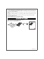
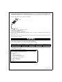
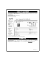
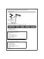
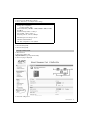
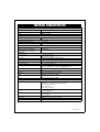
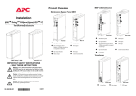
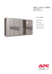
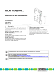
Network
Management
Card &
Modbus/
Jbus
(66123)
Installation manual
2 - 3402230800/AC
The Network Management Card & Modbus/Jbus (66123) is recommended for central UPSs protecting entire
networks or for UPS units backing up critical loads. With the card installed, the UPS has its own IP address and
uses the local computer capabilities to:
◗ Supply web pages (http or https (SSL)) with information on status conditions and measurements/settings/
alarms,
◗ Integrate an SNMP-based NMS such as HP OpenView, IBM Tivoli Netview and Computer Associates
Unicenter,
◗ Communicate with shutdown modules installed on the protected servers (Network Shutdown Module),
◗ Send e-mail and SMS messages,
◗ Control the ON/OFF function of the UPS and the outlets,
◗ Monitor the Environment Sensor (optional, cat. no. 66846).
UNPACKING AND CHECKS
◗ One Network Management Card & Modbus/Jbus (66123)
◗ One serial cable for configuration (3402226700),
◗ One installation manual (34022308EN).
Network
Management
Card &
Modbus/
Jbus
(66123)
Installation manual
Settings
/Sensor
100M
10M
Settin
UPS
gs/Se
nsor
data
RS232
66103
100M
10M
UPS
data
RS23
2
6610
3
3402230800/AC - 3
.
OVERVIEW
Jbus/modbus port
MAC address
ETHERNET 10/100BT port
000623001C07
Service port (Settings/Sensor)
Orange LED: RS232 activity
Settin
gs/Sen
100M
sor
10M
UPS
data
RS232
6612
3
Green LED: communication
with the UPS
Catalogue number
Orange LED: 10/100M
Green LED: connection +
activity
INDICATIONS
ETHERNET port
LED
Colour
ACT
Green
100M
Orange
Status
◗ OFF
◗ ON
◗ Flashing
◗ OFF
◗ ON
Description
◗ Card not connected to network
◗ Card connected to network, but no activity
◗ Port is sending/receiving
◗ Port operating at 10 Mbits/s
◗ Port operating at 100 Mbits/s
Service port (Settings/Sensor)
LED
Colour
Status
Description
UPS Data
Green
◗ OFF
◗ ON
◗ Flashing
◗ Card starting
◗ Communicating with UPS
◗ Normal operation
RS232
Orange
◗ OFF
◗ ON
◗ Configuration menu activated
◗ Normal operation
◗ Flashing
◗ Communication with Environment Sensor (option)
Communication with UPS is operational
Configuration menu not activated
4 - 3402230800/AC
The Network Management Card & Modbus/Jbus (66123) can be hot-plugged in MGETM GalaxyTM 7000
equipped with a Minislot. It is not necessary to shutdown the UPS, disconnect the load or restart the UPS.
◗ Note the MAC address of the card before inserting it.
UPS
Settings/
Sensor
100M
10M
UPS
data
RS232
66103
ETHERNET
◗ Insert and secure the card with the screws.
◗ Connect the ETHERNET cable.
◗ Check the ETHERNET port indications.
◗ Wait until the UPS Data LED flashes regularly (approx. two minutes), indicating that card start-up has
terminated correctly.
Note. Connection detection continues until the card has been connected to the network. Once connection is
made, card start-up continues.
IP SETTINGS
Once the card has started, proceed as indicated below.
◗ Connect the serial cable to card’s service port and PC’s COM port
◗ Use a terminal emulator such as HyperTerminalTM with these settings
Bits per second
Data bits
Stop bits
9600
8
1
"Echo typed characters locally" option: disabled
Parity
none
Flow control
none
◗ Type MGEUPS (or mgeups).
The main configuration menu is displayed:
APC by Schneider Electric
Network Management Card & Modbus/Jbus
Release : AB.build_5_0_7
1 : Reset
2 : Network configuration
3 : Set Login Password to Default
4 : Return to Default Configuration
5 : Jbus configuration
6 : Sensor configuration
0 : Exit
3402230800/AC - 5
Your network is equipped with a BOOTP/DHCP server (default)
The card is configured by default with this service enabled. No manual configuration is required.The IP
parameters are automatically collected by the card.
From the main configuration menu: (see above)
◗ Press the 2 key (Network configuration).
◗ Press the 1 key(Read Network settings).
The settings supplied by the server are displayed:
Network configuration :
MAC address : 00:06:23:00:1C:07
Mode : DHCP
IP address : 172.17.23.18
Subnet mask : 255.255.248.0
Gateway : 172.17.17
◗ Note the IP address.
◗ Press the 0 key (Exit).
◗ Press the 0 key (Exit).
You can also use MUPGRADE software utility to view the card IP adress
Provided on the Solution-Pac 2 CD-ROM or at www.mgeups.com. It must be installed on a network connected
PC.
Your network is not equipped with a BOOTP/DHCP server
Manual configuration is required.
To set the network configuration, use terminal emulation (see above)
From the main configuration menu:
◗ Press the 2 key (Network configuration).
◗ Press the 2 key (Modify Network settings).
◗ Follow the instructions and enter the IP parameters:
1 : Read Network settings
2 : Modify Network settings
3 : Set ethernet speed
0 : Exit
For each of the following questions, you can press "Return" to select
the value shown in braces, or you can enter a new value
Should this target obtain IP settings from the network?[N] N
Static IP address [172.17.16.16]?172.16.1.82
Subnet mask IP address [255.255.0.0]? 255.255.255.0
Gateway address IP address [0.0.0.0]? 172.17.17.1
Done
Wait until "Done" is displayed, indicating that the IP parameters have been saved.
◗ Press the 0 key (Exit).
◗ Press the 1 key (Reset).
◗ Press the 2 key (Restart).
The card restarts with the new IP settings (after approx. one minute).
6 - 3402230800/AC
ACCESS TO SUPERVISION
To check whether the Network Management Card & Modbus/Jbus (66123) is operational after installation
and configuration, proceed as follows.
◗ Run a browser
◗ Enter in the address bar:
http://IP address/ (e.g. http://172.16.1.82/)
◗ The home page is displayed
◗ Set the time by clicking the Time command.
◗ Continue configuration via the sections in the Settings menu.
USER MANUAL
This manual provides all the information required to install and configure the Network Management Card &
Modbus/Jbus (66123).
For more information on the supervision, control and configuration functions offered by the Network
Management Card & Modbus/Jbus (66123), see the user manual on the www.apc.com web site.
3402230800/AC - 7
SENSOR CONNECTION (option)
ETHERNET
The Environment sensor is a Network Management Card & Modbus/Jbus option.
The sensor remotely monitors the UPS environment by regularly measuring the temperature and humidity, and
checking the states of two external contacts. It can also send alarms (e-mail, SNMP trap) tripped by pre-set
thresholds.
Connection is made via the Service port (Settings/Sensor) on the Network Management Card & Modbus/
Jbus. The sensor is detected automatically. Configuration and supervision use a menu that may be accessed
directly from the home page. For more information, see the user manual of the Network Management Card
& Modbus/Jbus.
ETHE
RNET
Settin
gs/Se
100M
100M
On =
Blink Link
= Act
nsor
10M
10M
UPS
UPS
data
data
RS23
RS232
2
661
66
1003
2
100M
10M
UPS
data
RS23
2
66103
UPS
8 - 3402230800/AC
JBUS/MODBUS
RS232 link configuration and connection
SA1
SA2
Pin Function
4
SG
3
2
1
Txd
SA2
Received data (input)
Not connected
Transmitted data (output)
Not connected
Signal ground
1
8
OFF
ON
5
1
2
3
4
5
Rxd
RS485 link configuration and connection
For proper operation, the polarity of EIA RS485 2-wire and 4-wire lines must be set at only one point and the
lines terminated at the end.
Polarity
Normally, the master of the network sets the polarity of the line. The receiver inputs have a true failsafe feature
wich eliminates the need for external bias resistors and ensures a logic high output level when the inputs are
open or shorted. This guarantees that the receiver outputs are in a known state before communication begins
and when communication ceases.
Termination
Termination is used to match impedance of a node to the impedance of the transmission line being used. When
impedance are mismatched, the transmitted signal is not completely absorbed by the load and a portion is
reflected back into the transmission line. The termination line is not necessary if the speed on the line is much
less than 115Kbauds
1
R-
RD = (A')
2
R+
TD = (B)
3
T-
TD = (A)
4
T+
5
0V
0V
SA2
SA1
SA2
SA1
1
1
8
8
OFF
ON
RD = (B')
OFF
ON
RS485
The default setting of the RS485 is a 4 wires configuration without polarity and without termination.
SA1 switches are used to make the termination and the topology of the line (2 or 4 wires). The termination
resistance value is 166 Ω.
SA1 description:
1 : reserved
2 : reserved
3 : link termination between T- to R- (2 wires configuration) if set to ON
4 : connection T- to R- (2 wires configuration ) if set to ON
5 : connection T+ to R+ (2 wires configuration ) if set to ON
6 : reserved
7 : reserved
8 : link termination between R+ and R- if set to ON
3402230800/AC - 9
2 wires connection
SA1
SA2
SA2
3
2
1
L-
L+
8
8
5V
OFF
ON
4
1
OFF
ON
5
SA1
1
3V3
3V3
Rp
polarity
L-
Ra
L-
connection
if end
of the line
L-
1
3
L-
3
termination
Ra
connection
if end
of the line
7
L+
1
3
Ra
termination
SA1-3
SA1-3
L+
L+
2
polarity
L+
4
2
4
Rp
0V
0V
transmit/receive
data
0V
transmit/receive
data
Card of an intermediate cabinet
Master unit
Card settings of an intermediate cabinet
ON
OFF
8 78 67 56 45 34 23 12 1
SA1
SA1
SA1
Link without polarity and without termination.
OFF
ON
SA2
Others settings
10 - 3402230800/AC
ON
OFF
8877665544332211
SA1
SA1
SA1
OFF
ON
SA2
Link with termination.
transmit/receive
data
Card of an end-of-line cabinet
4 wires connection
SA2
SA1
SA2
3
T+ T-
Rp
2
1
8
R + R-
master
transmitt
5V
8
OFF
ON
4
1
OFF
ON
5
SA1
1
slave
receiver
polarity
T-
R-
slave
receiver
R-
Rtermination
1
Ra
1
Ra
termination
T+
polarity
R+
2
R+
R+
2
Rp
0V
Rp
Ra
transmit data
receive data
receive data
5V
slave
receiver
R-
slave
transmitt
T-
connection if
end of the line
T-
T-
3
slave
transmitt
3
connection if
end of the line
R+
T+
4
T+
T+
4
Rp
0V
receive data
Master unit
transmit data
Card of an intermediate cabinet
transmit data
Card of an end-of-line cabinet
Card settings of an intermediate cabinet
ON
OFF
87654321
SA1
SA1
Link without polarity and without termination.
OFF
ON
SA2
Others settings
ON
OFF
87654321
SA1
SA1
Link with termination.
OFF
ON
SA2
3402230800/AC - 11
Configuration of the JBUS/MODBUS communication parameters
ETHERNET
Through settings port
ETHE
RNET
Setting
s/Sens
or
100M
100M
On =
Blink Link
= Act
10M
10M
UPS
UPS
data
data
RS232
RS23
2
66103
661
02
100M
10M
UPS
data
RS232
66103
UPS
Connect the RS232 link to a
terminal
(Microsoft Hyper terminal)
◗ Use the cord supplied with the card
◗ Connect the card to a computer
◗ Use a terminal emulator such as HyperTerminalTM with these settings
Bits per second
Data bits
Stop bits
9600
8
1
"Echo typed characters locally" option: disabled
◗ Check that UPS power is on.
◗ Type MGEUPS (or mgeups).
The main configuration menu is displayed::
APC by Schneider Electric
Network Management Card & Modbus/Jbus
Release : AB.build_5_0_7
1 : Reset
2 : Network configuration
3 : Set Login Password to Default
4 : Return to Default Configuration
5 : Jbus configuration
6 : Sensor configuration
0 : Exit
◗ Press the 5 key (Jbus configuration).
The Jbus configuration menu is displayed:
Jbus settings
1 : Display Jbus settings
2 : Modify Jbus settings
3 : Display Jbus diagnostics
4 : Reset Jbus diagnostics
5 : Return to Jbus Default Configuration
6 : Display Jbus frames
0 : Exit
12 - 3402230800/AC
Parity
none
Flow control
none
◗ Press the 2 key (Modifiy Jbus settings)
◗ Press «Return» key to modify the Jbus settings
Setting Jbus configutration
Set Slave number : 0x1*
Set the Baud Rate [1:38400,2: 19200, 3:9600, 4: 4800, 5: 2400,
6: 1200] :3
Set data format[1: 8 bits, 2: 7 bits] :1
Set stop bit[1: 1 bits, 2: 2 bits] :1
Set parity [1: None, 2: Even, 3: Odd] :1
Wait during the new setting is saved ...
TLS/Slave JBUS initialized
The Jbus configuration is now updated.
* Hex format.
◗ Press the 0 key (Exit).
◗ Press the 0 key (Exit).
Through a web browser
◗ Run a browser
◗ Enter in the address bar:
http://IP address/ (e.g. http://172.16.1.82/)
◗ The home page is displayed
◗ Select the setting menu
3402230800/AC - 13
◗ Set the parameters.
◗ Select the «Save» button to save the new parameters.
14 - 3402230800/AC
TECHNICAL CHARACTERISTICS
Physical characteristics
Dimensions (W x D x H)
132 x 66 x 42 mm
Weight
70 g
RoHS
100% compatible
Storage
Storage temperature range
-10°C to 70°C
Ambient conditions
Operating temperature range
0°C to 40°C
Relative humidity
90% RH max. without condensation
Card performance
Supply voltage
5V ±5%
Supply current (all LEDs ON and
Environment Sensor connected)
300 mA max.
Functions
Web supervision
5 browsers max. (http),
3 browsers max. (https)
Languages
English, French, German, Italian, Spanish
Alarms
E-mail, SNMP TRAP, Web page
Log
400 measurements or events
Server protection
Up to 35 servers protected
Network
Fast ETHERNET, 10/100 Mbits, auto-negotiation
HTTP 1.1, SNMP V1, NTP, TFTP, SMTP, BOOTP/DHCP
Identification
User name and password
Security
SSL 3.0, TLS 1.0
Browsers
Microsoft Internet Explorer 6.x or higher
NMS
Enterprise Power Manager (EPM)
Management-Pac 2
MIB
MIB II standard - MGE V1.7 MIB
Settings (default values)
IP network
BOOTP/DHCP enabled
IP address: 172.17.16.16 (manual configuration)
Subnet mask: 255.255.0.0
Gateway: 0.0.0.0
NTP server: pool.ntp.org
Web-page access control
User name: MGEUPS
Password: MGEUPS
Service-port menu access control
Password: MGEUPS or mgeups
(not modifiable)
Date and time
Synchronise with an NTP server (GMT)
Service port
9600 bits/s, 8 bits, 1 bit stop, no parity
RS485 port
Slave nb:0x01, 9600 bits/s, 8 bits, 1 bit stop, no parity
3402230800/AC - 15
ELECTROMAGNETIC COMPATIBILITY
When correctly installed and used in accordance with manufacturer instructions, the card complies with the
following standards:
◗ ITE (Information Technology Equipment) safety: IEC/EN 60950-1 2005
◗ EMC: EN 61000-6-2 (2005), EN 61000-6-3 (2006), IEC/EN 62040-2 (2005)
In compliance with European directives:
◗ Low voltage: 2006/95/EEC.
◗ EMC: 2004/108/EEC.
Federal Communication Commission (FCC) statement
This equipment has been tested and found to comply with the limits for a Class B digital device, pursuant to
part 15 of the FCC rules. These limits are designed to provide reasonable protection against harmful
interference when the equipment is operated in a commercial environment.
3402230800/AC
990-3402230800AC