1
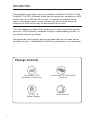
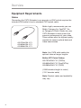
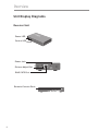
OmniView®
CAT5 Extender
User Manual
F1D084vea2
Table of Contents
1.
Introduction .......................................................................... 1
Package Contents..................................................................... 1
2.
Overview ............................................................................... 2
Feature Overview ................................................................. 2
Equipment Requirements ...................................................... 3
System Requirements ........................................................... 4
Unit Display Diagrams .......................................................... 5
Specifications ...................................................................... 7
3.
Installation ............................................................................ 8
Pre-Configuration ................................................................. 8
Connecting the Transmitter to the Computer or KVM Switch ... 9
Connecting the Local Console to the Transmitter ..................... 9
Connecting the Remote Console to the Receiver ................... 10
Connecting the Transmitter to the Receiver ............................ 11
Powering up the Systems ....................................................... 11
4.
Using the CAT5 Extender ......................................................12
LED Operation ........................................................................ 12
Adjusting the Picture ................................................................13
Troubleshooting Tips ...............................................................13
5.
Information ......................................................................... 14
Introduction
Congratulations and thank you for purchasing the Belkin OmniView CAT5
Extender. The CAT5 Extender allows you to control your computer or KVM
switch from up to 300 feet (91m) away. It is perfect for isolated server
rooms, large server farms, secure systems, or test benches where the
computer or KVM switch may be inaccessible to the user.
This User Manual provides all the details you’ll need to install and operate
your new CAT5 Extender, in addition to expert troubleshooting advice—in
the unlikely event of a problem.
We appreciate your business and are confident that you will soon see for
yourself why over 1 million Belkin OmniView products are in use worldwide.
Package Contents
OmniView CAT5
Extender Transmitter
5V AC, 1A
Power Supply
1
OmniView CAT5 Extender
Receiver
User Manual
Overview
1
CAT5 Technology
2
Integrated CAT5 technology enables you to connect your KVM switch
to your servers up to 300 feet (91m) away using standard CAT5 cabling.
CAT5 cabling reduces cable bulk and simplifies cable management.
3
4
Video Resolution
The CAT5 Extender supports video resolutions of up to 1600x1200@75Hz.
5
Local and Remote Ports
The CAT5 Extender features local and remote console ports, enabling you
to control your computers from near or far.
Built-In Cabling
A built-in, 3-foot, all-in-one KVM cable provides an easy connection
between the CAT5 Extender and your computer or KVM switch.
LED Display
An LED display on the Transmitter and Receiver units provides quick
status monitoring. An orange LED indicates power is being supplied to the
unit. A flashing green LED indicates whether the Transmitter or Receiver
has control.
2
section
Feature Overview
Overview
Equipment Requirements
Cables
Connecting the CAT5 Extender to a computer or KVM switch requires the
included KVM cable kit and a standard CAT5 patch cable.
A3L791bXXM-YYY
A3L850bXXM-YYY
A3L980bXXM-YYY
Belkin highly recommends you use
Belkin Category 5e, FastCAT™ 5e,
or Category 6 Patch Cables for your
CAT5 Extender to help ensure the
superior performance of your video.
These cables offer the highest quality
possible to ensure optimal data and
video transmission.
Note: Use CAT6 solid cables for
optimal video at longer lengths.
Belkin UTP Patch Cables:
A3L791bXXM-YYY (CAT5e)
A3L850bXXM-YYY (FastCAT5e)
A3L980bXXM-YYY (CAT6)
(-XXM denotes length in meter)
(-YYY denotes color)
Note: Product codes and availability
may vary.
3
Overview
1
OS Platforms
2
The CAT5 Extender is compatible with CPUs running on, but not limited to,
the following OS platforms:
3
• Windows® NT®, 95, 98, 2000, Me, XP, Server 2003
4
• Microsoft DOS 5.x and above
®
• Red Hat Linux 8.x and above
®
®
5
• Novell NetWare 5.x
®
®
• UNIX
®
Keyboards
• PS/2-compatible
• Supports 101-/102-/104-/106-standard-key keyboards
Mice
• PS/2-compatible mice having 2, 3, 4, or 5 buttons
• PS/2-compatible wireless and optical mice
Monitors
• CRT and LCD (with VGA support)
4
section
System Requirements
Overview
Unit Display Diagrams
Receiver Unit
�����
�����
�����
��
Power LED
��
��
Control LED
����
������
���
�
���
Power Jack
Picture-Adjust Dial
RJ45 CAT5 Port
Remote-Console Ports
5
�������
����
��������
Overview
1
3
Keyboard PS/2 Cable
4
��
��
��
� ��
��
5
Monitor VGA Cable
��
���
���
���
��
���
��
��
���
��
�
Mouse PS/2 Cable
����
���
Local-Console Ports
Power LED
Control LED
����
RJ45 CAT5 Port
6
section
2
Transmitter Unit
Overview
Specifications
Part No.:
F1D084vea2
Enclosure:
Metal enclosure
Receiver Power:
5V, 600mA power adapter with center-pin
negative polarity
Transmitter Power:
5V, 220mA (from attached computer or
KVM switch via keyboard port)
Max. Video Resolution:
Up to 1600x1200 @ 75Hz (depends on
cable length)
Keyboard Emulation:
PS/2
Mouse Emulation:
PS/2
Console Keyboard Input:
MiniDIN6 (PS/2)
Console Mouse Input:
MiniDIN6 (PS/2)
Console Monitor Ports:
HDDB15 female (VGA)
CAT5 Extension Ports:
RJ45
Operating Temp:
32° to 104° F (0° to 40° C)
Storage Temp:
-4° to 140° F (-20° to 60° C)
Humidity:
0-80% RH, non-condensing
Warranty:
2 years
Dimensions:
Transmitter: 4.5 x 3.3 x 0.9 in.
(115 x 85 x 24mm)
Receiver: 5.8 x 3.4 x 1.0 in.
(148 x 86 x 26mm)
Weight:
Transmitter: 14.7 oz. (0.42kg.)
Receiver: 13.5 oz. (0.38kg.)
Note: Specifications are subject to change without notice.
7
Installation
1
Consider the following when deciding where to place the CAT5
Extender:
2
• the lengths of the cables attached to your keyboard, monitor, and
mouse
• the location of your computer or KVM switch
• the lengths of the cables you’ll use to connect the Transmitter and
Receiver units
3
Cable-Distance Requirements
4
5
VGA signals transmit best at shorter cable lengths. At longer cable
lengths, the probability of video degradation increases. For this reason,
Belkin recommends that the length of the CAT5 patch cable between the
Transmitter and Receiver units does not exceed 300 feet (91m).
Warning! Avoid placing cables near fluorescent lights, air-conditioning
equipment, or machines that create electrical noise (e.g., vacuum
cleaners).
You are now ready to begin installation of your CAT5 Extender. The
following sections (pages 9–11) provide complete instructions for the
hardware setup of a CAT5 Extender (F1D084vea2).
8
section
Pre-Configuration
Installation
Step 1 Connecting the Transmitter to the Computer
or KVM Switch
1.1 Disconnect all computers from the electrical power supply.
1.2 Using the Transmitter unit, connect the built-in VGA and PS/2
cables to the monitor, keyboard, and mouse ports on your
computer or to the console ports on your KVM switch. (Refer to
diagram below.)
Transmitter
Step 2 Connecting the Local Console to the Transmitter
2.1 From your local console, connect your monitor to the VGA console
port on the Transmitter unit. (Refer to diagram below.)
2.2 Connect your keyboard and mouse to the PS/2 console ports on
the Transmitter unit. (Refer to diagram below.)
Transmitter
9
Installation
Step 3 Connecting the Remote Console to the Receiver
1
3.1 From your remote console, connect your monitor to the VGA
console port on the Receiver unit.
2
3
4
5
Receiver
10
section
3.2 Connect your keyboard and mouse to the PS/2 console ports on
the Receiver unit.
Installation
Step 4 Connecting the Transmitter to the Receiver
Using a CAT5 cable, connect one end into the RJ45 port on the Transmitter
unit. Connect the other end to the RJ45 port on the Receiver unit. (Refer to
diagram below.)
�������
����
��������
Step 5 Powering up the Systems
5.1 Attach the power adapter to the power jack on the Receiver unit.
Connect the adapter to a power source to power up the Receiver
unit. The Transmitter unit will receive power from the computer or
KVM switch to which it is connected.
5.2 Power up your computers and KVM switch.
11
Using the CAT5 Extender
Once the CAT5 Extender is installed, the video will display at both
the local and remote consoles. However, only one console can have
control of the mouse and keyboard input at one time. The control is
determined automatically.
1
To gain control, the active console must remain idle for two seconds.
3
The orange Power LED indicates if the Transmitter and Receiver units are
powered on. The green Control LED indicates which console has control.
If the Control LED on the Transmitter is blinking, the remote console (or
Receiver) has control. If the Control LED on the Receiver is blinking, the
local console (or Transmitter) has control.
Transmitter LEDs
Receiver LEDs
Color
Indication
Orange
Power is on
Green
Blinks when remote console has control
Orange
Power is on
Green
Blinks when local console has control
4
5
12
section
LED Operation
2
Using the CAT5 Extender
Adjusting the Picture
When the remote console has control, you can adjust the picture quality
using a small flat screwdriver to turn the Picture-Adjust Dial on the back
panel of the Receiver unit.
Troubleshooting Tips
• Use the Picture-Adjust Dial to improve video quality for longer cable
lengths.
• Avoid using a specialized mouse. Mice with scrolling wheels are
supported.
• Avoid using a specialized keyboard (e.g., a keyboard with special shortcut
keys).
• The CAT5 Extender is not compatible with serial mouse ports or KVM
switches using serial mice at the console.
13
Information
FCC Statement
1
2
Declaration of Conformity with FCC Rules
for Electromagnetic Compatibility
4
5
CE Declaration of Conformity
We, Belkin Corporation, declare under our sole responsibility that the product F1D084, to which
this declaration relates, is in conformity with Emissions Standard EN55022 and with Immunity
Standard EN55024, LVP EN61000-3-2, and EN61000-3-3.
ICES
This Class B digital apparatus complies with Canadian ICES-003. Cet appareil numérique de la
classe B est conforme á la norme NMB-003 du Canada.
Belkin Corporation Limited 2-Year Product Warranty
What this warranty covers.
Belkin Corporation warrants to the original purchaser of this Belkin product that the product shall
be free of defects in design, assembly, material, or workmanship.
What the period of coverage is.
Belkin Corporation warrants the Belkin product for two years.
What will we do to correct problems?
Product Warranty.
Belkin will repair or replace, at its option, any defective product free of charge (except for
shipping charges for the product).
What is not covered by this warranty?
All above warranties are null and void if the Belkin product is not provided to Belkin Corporation
for inspection upon Belkin’s request at the sole expense of the purchaser, or if Belkin Corporation
determines that the Belkin product has been improperly installed, altered in any way, or tampered
with. The Belkin Product Warranty does not protect against acts of God (other than lightning)
such as flood, earthquake, war, vandalism, theft, normal-use wear and tear, erosion, depletion,
obsolescence, abuse, damage due to low voltage disturbances (i.e. brownouts or sags),
non-authorized program, or system equipment modification or alteration.
14
section
We, Belkin Corporation, of 501 West Walnut Street, Compton, CA 90220, declare under our
sole responsibility that the products:
F1D084
to which this declaration relates:
Comply with Part 15 of the FCC Rules. Operation is subject to the following two conditions:
(1) this device may not cause harmful interference, and (2) this device must accept any
interference received, including interference that may cause undesired operation.
3
Information
How to get service.
To get service for your Belkin product you must take the following steps:
1. Contact Belkin Ltd. at Express Business Park, Shipton Way Rushden, NN10 6GL, United
Kingdom, Attn: Customer Service, or call 00 800 223 55 460, within 15 days of the
Occurrence. Be prepared to provide the following information:
a. The part number of the Belkin product.
b. Where you purchased the product.
c. When you purchased the product.
d. Copy of original receipt.
2. Your Belkin Customer Service Representative will then instruct you on how to forward your
receipt and Belkin product and how to proceed with your claim.
Belkin Corporation reserves the right to review the damaged Belkin product. All costs of
shipping the Belkin product to Belkin Corporation for inspection shall be borne solely by the
purchaser. If Belkin determines, in its sole discretion, that it is impractical to ship the damaged
equipment to Belkin Corporation, Belkin may designate, in its sole discretion, an equipment
repair facility to inspect and estimate the cost to repair such equipment. The cost, if any, of
shipping the equipment to and from such repair facility and of such estimate shall be borne
solely by the purchaser. Damaged equipment must remain available for inspection until the
claim is finalized. Whenever claims are settled, Belkin Corporation reserves the right to be
subrogated under any existing insurance policies the purchaser may have.
How state law relates to the warranty.
THIS WARRANTY CONTAINS THE SOLE WARRANTY OF BELKIN CORPORATION, THERE
ARE NO OTHER WARRANTIES, EXPRESSED OR, EXCEPT AS REQUIRED BY LAW, IMPLIED,
INCLUDING THE IMPLIED WARRANTY OR CONDITION OF QUALITY, MERCHANTABILITY OR
FITNESS FOR A PARTICULAR PURPOSE, AND SUCH IMPLIED WARRANTIES, IF ANY, ARE
LIMITED IN DURATION TO THE TERM OF THIS WARRANTY.
Some states do not allow limitations on how long an implied warranty lasts, so the above
limitations may not apply to you.
IN NO EVENT SHALL BELKIN CORPORATION BE LIABLE FOR INCIDENTAL, SPECIAL,
DIRECT, INDIRECT, CONSEQUENTIAL OR MULTIPLE DAMAGES SUCH AS, BUT NOT
LIMITED TO, LOST BUSINESS OR PROFITS ARISING OUT OF THE SALE OR USE OF ANY
BELKIN PRODUCT, EVEN IF ADVISED OF THE POSSIBILITY OF SUCH DAMAGES.
This warranty gives you specific legal rights, and you may also have other rights, which may
vary from state to state. Some states do not allow the exclusion or limitation of incidental,
consequential, or other damages, so the above limitations may not apply to you.
15
OmniView®
CAT5 Extender
Belkin Tech Support
Europe: 00 800 223 55 460
Belkin Ltd.
Express Business Park, Shipton Way
Rushden, NN10 6GL, United Kingdom
+44 (0) 1933 35 2000
+44 (0) 1933 31 2000 fax
Belkin GmbH
Hanebergstrasse 2
80637 Munich, Germany
+49 (0) 89 143405 0
+49 (0) 89 143405 100 fax
Belkin SAS
130 rue de Silly
92100 Boulogne-Billancourt, France
+33 (0) 1 41 03 14 40
+33 (0) 1 41 31 01 72 fax
Belkin Iberia
Avda. Cerro del Aguila 3
28700 San Sebastián de los Reyes
Spain
+34 91 625 80 00
+34 902 02 00 34 fax
Belkin B.V.
Boeing Avenue 333
1119 PH Schiphol-Rijk, The Netherlands
+31 (0) 20 654 7300
+31 (0) 20 654 7349 fax
© 2006 Belkin Corporation. All rights reserved. All trade names are registered trademarks of
respective manufacturers listed. Windows, NT, and Microsoft, are either registered trademarks
or trademarks of Microsoft Corporation in the United States and/or other countries.
P74592vea2