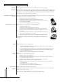
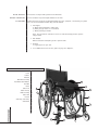
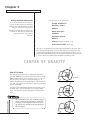
1
O W N E R ’ S
RazorBlade
Saber
Spazz-G
Little
Dipper
Chump-G
Boing!
Spazz
M A N U A L
© 2010 Colours in Motion. All rights reserved
Chump
Eclipse
Spazz-K
RazorBlade Jr.
ShockBlade
Krypto
Zephyr
c o l o u r s w h e e l c h a i r. c o m
WELCOME TO THE WORLD OF COLOURS!
Congratulations on your purchase of a Colours wheelchair, the finest ultra-light
wheelchair in the world. Colours wheelchairs are hand-crafted to ensure the highest
quality possible. By selecting Colours you can now rely on prompt and friendly
service.
The designers as well as many of the employees at Colours are wheelchair users, so
there is a wealth of practical experience built into your wheelchair.
Colours in Motion
860 E. Parkridge Avenue
Corona, CA 92879, U.S.A.
Toll Free: 800-892-8998
Tel: 951.808.9131
Fax: 951.808.9949
www.colourswheelchair.com
By understanding our customers need for independence and mobility, we at Colours
are committed to doing everything we can to help you get the optimal use of your
new wheelchair.
To realize the greatest benefits from your wheelchair it is important that you first
read this manual. It is designed to help you understand how your chair is built and
how it should be adjusted to give you maximum comfort and safety. No wheelchair
will work well if it is not adjusted precisely for its user. So please, read this manual
carefully before using your new wheelchair.
Thank you for choosing Colours.
i
O W N E R ’ S
M A N U A L
C
CHAPTER 1
CHAPTER 2
SAFETY TIPS . . . . . . . . . . . . . . . . . . . . . . . .
GETTING TO KNOW YOUR CHAIR . . . . . . . . . . .
COLOURS EVERY DAY CHAIRS
GETTING IT RIGHT . . . . . . . . . . . . . . . . . . . .
Part 1 Standard adjustments/ Center of Gravity
Center of gravity (SABER) . . . . . . .
Backrest angle . . . . . . . . . . . . . . .
Brakes . . . . . . . . . . . . . . . . . . . .
Quick releases . . . . . . . . . . . . . . .
Footrest/ Wheels . . . . . . . . . . . . .
Backrest height/shocks . . . . . . . . .
Part 2 Advance adjustments . . . . . . . . . . . . .
Rear seat height . . . . . . . . . . . . . .
Front seat height . . . . . . . . . . . . .
camber angle . . . . . . . . . . . . . . . .
Caster Housing (SABER) . . . . . . . . .
Camber/ Wheel Alignment . . . . . . .
CHAPTER 3
CHAPTER 4
MAINTENANCE, WARRANTY & ACCESSORIES . . . .
Service & maintenance . . . . . . . . .
Maintenance schedule . . . . . . . . . .
Troubleshooting . . . . . . . . . . . . . .
Warranty . . . . . . . . . . . . . . . . . . .
Accessories . . . . . . . . . . . . . . . . .
Register Card . . . . . . . . . . . . . . . .
O
N
T
E
N
T
S
1
2
3-4
5
6
7
8
9
9
10
11
11
12
12
12
12
14
15
15
16
16
17
17-18
19
Chapter 1
S
A
F
E
T
Y
PAT I E N C E
TEAMWORK
CONTROL
SAFETY CHECK
C O N S U LT
WEIGHT SHIFT
T
I
P
Always start slowly. You will grow into the feel of your chair. By trying to do to much to soon, you
could run the unnecessary risk of injury to yourself and others.
Have someone assist as you familiarize yourself with your wheelchair. Each new maneuver could pose a
potential risk of injury. Backward movements are especially tricky. Always have someone working with
you until you attain a level of proficiency when operating your wheelchair. Whenever anyone assists
you, it is important that they too read the owners manual prior to getting started.
Avoid unnecessary risks such as high speeds, quick turns and leaning backward. In addition, avoid
running over objects which could cause you to stop suddenly or capsize.
You should always perform a safety check of your wheelchair before each use.
Talk to your doctor, nurse or therapist prior to operating your wheelchair to determine safe methods of
operation that suit you best.
Certain shifts in your weight while dressing or performing a physical activity may create a potential
hazard. If these functions are not done properly, they could result in a fall or capsizing of the chair.
To help prevent this:
1.
2.
3.
4.
ii
O W N E R ’ S
M A N U A L
S
Position the front casters forward.
Make sure the anti-tippers (if installed) are locked and in the downward position.
Move the rear of the chair so that it is against a wall.
Lock both rear wheels.
S
A
F
E
T
Y
WHEELIE
D O O R WAY S
EXTENDING, REACHING OR
LEANING
T
I
S
This is a dangerous maneuver and we do not recommend its use without assistance.
The safest way to operate the chair is on level floors that are free of obstacles. Whenever possible use
a ramp to enter or exit a facility. Keeping your hands on the push rims will allow you to maintain maximum balance. Do not try to force yourself over an obstruction by propulsion and never use the sides
of a doorway to pull yourself through a passageway.
It is best to avoid reaching or leaning forward when operating your wheelchair. If circumstances arise
that make leaning forward unavoidable you should:
1.
2.
3.
4.
5.
N AV I G AT I N G I N C L I N E S
P
Position the casters in the forward position.
Maneuver your chair as close to the desired object as possible.
Secure yourself with one hand by holding on to the arm rest or rear wheel.
Do not lock the rear wheels.
It is best to avoid applying pressure on the footrest.
When traveling up or down a hill, it is recommended that you:
BANKED SLOPE
1.
2.
3.
4.
Maintain a straight course.
Never turn on a hill due to the danger of toppling.
Avoid stopping, it can potentially cause you to lose control of the chair.
Maintain a slow and controlled speed, by applying steady pressure on the
push rims.
5. Do not use the brakes to slow down or stop the wheelchair, this could cause
it to seize up, causing you to lose control.
6. Whenever possible, utilize help from an assistant while navigating inclines.
DECLINING SLOPE
It is important to note that hills and slopes can be hazardous, even with the use of
anti-tippers.
INCLINING SLOPE
CURBS
When negotiating curbs it is suggested that:
1. Whenever possible get help from an assistant (if you have assistance make sure that your
chair is equipped with push handles).
2. Avoid hard impacts when descending a curb. A hard impact could adversely affect the chair.
3. If being assisted, the chair should be lowered, by gently rolling the rear wheels down the
curb, from a backward position.
4. Never try to scale or descend curbs that exceed a normal height.
S TA I R S
When going up or down a staircase you should:
1. Always use two or more assistants.
2. One assistant should be positioned at the rear of the chair and one assistant should be
positioned at the front of the chair.
3. Always secure the chair by holding non-detachable positions on the frame.
4. When ascending a staircase, position the chair backward.
5. When descending a staircase, position the chair forward, tilt the chair back and roll down
one step at a time.
6. The assistant to the rear is always in control.
7. The chair must have push handles when negotiating stairs.
E S C A L AT O R S
STREETS
Never use an escalator for transport, use an elevator.
Always use extreme caution when crossing streets. Reflective tape on the chair or your clothing will
make you more visible to drivers.
Check local laws regarding wheelchair use as they vary from state to state.
1
O W N E R ’ S
M A N U A L
MOTOR VEHICLES
W E I G H T L I M I TAT I O N S
ACCESSORIES
Do not drive or transport with a patient in the wheelchair.
Do not exceed the 250 pound weight limitation of the chair.
Certain maneuvers should not be attempted without the proper equipment. The following is a partial
list of accessories available and when they could be utilized:
1. Anti-Tippers:
a) When leaning backwards or tilting chair
b) When going up inclines or over obstacles
c) When performing a wheelie
Note: It is important to remember to remove or rotate the anti-tipper tubes up when
being assisted.
2. Push Handles:
When an assistant is attempting to tilt or push the chair.
3. Arm Rest:
To supply support for your arms.
4. For an additional list of accessories, please see page 36 in Chapter 4.
3
GETTING TO KNOW YOUR CHAIR
Frame
Cushion
Backrest
Rear Wheel assembly
Rear Wheel Quick Release
Push Rim
Caster
Caster Fork
Caster Housing
Brake assembly
Caster Axle
Footrest
Seat Sling (seat frame)
Side Guards
1
2
3
4
5
6
7
8
9
10
11
12
13
14
14
4
2
6
13
5
1
10
9
8
11
2
O W N E R ’ S
M A N U A L
7
12
Chapter 2
COLOURS EVERYDAY CHAIRS
Zephyr
RazorBlade
Boing!
ShockBlade
S a be r
3
O W N E R ’ S
M A N U A L
Spazz-G
COLOURS EVERYDAY CHAIRS
Spazz
Eclipse
RazorBlade jr.
Chump
Little Dip per
S pa z z - K
Kry pto
4
O W N E R ’ S
M A N U A L
Chapter 3
GETTING IT RIGHT
PART 1
Making the Proper Adjustments
S TA N D A R D
As you go through the process of fine tuning your new Colours chair, you will experience how much small adjustments effect the
way your chair “feels” and “performs.”
A D J U S T M E N T S
CENTER OF GRAVITY
BACKREST ANGLE
BRAKES
Review this checklist with your Colours representative to make sure you get the maximum performance from your Colours
wheelchair.
QUICK RELEASES
FOOTREST
BACKREST HEIGHT
WHEELS
SHOCKS
(Boi ng! & Sho ckBl ade only)
REAR SEAT HEIGHT
(Saber on ly)
The sections, on adjustments to the chair, have been divided into two parts. Part 1
deals with standard adjustments. Part Two deals with advanced adjustments. We
recommend that all adjustments be made by an authorized Colours dealer. It is important that you DO NOT attempt any of the advanced adjustments discussed in part
2. Those sections are included solely to familiarize you with your chair.
C E N T E R O F G R AV I T Y
What It’s All About
One of the most important factors in designing a wheelchair is
geometry. Establishing your sitting position and center of gravity
(COG) is what allows the chair to become a part of you. This enables the chair to work with you instead of against you. In
essence, establishing the correct COG equates to having balance in
your chair. This is why it is so important to determine your sitting
position and the COG.
MORE “TIP”
This adjustment is individualized and will depend greatly on your
wheelchair skills. It is important that you consult your dealer
and/or clinician before experimenting with the rear wheel alignment.
The Performance of the chair will depend greatly
on the accuracy of this adjustment. Remember
to always test the degree to which the chair will
tip, and how this changes as the rear wheel position is changed.
5
O W N E R ’ S
M A N U A L
LESS “TIP”
CENTER O F G R AV I T Y
Changing the Center Of Gravity (Eclipse,Lil Dipper,)
The Center Of Gravity is changed by moving the rear axle position forward or
back. The following steps are how it is done:
1. Push the Rear Wheel Quick Release button. (Refer to “Quick Releases”
on page 16.)
2. Remove the rear wheel.
3
3. Loosen the large nut on the inside of the axle plate/camber plate.
Once the nut is loosened enough to free the guiding pin on the outside of the axle plate, move the axle receiver forward (to allow the
chair to tip more) or to the rear (to make the chair tip less).
4. Place the guiding pin in desired hole and re-tighten the nut on the inside of the axle plate. Make sure the guiding pin is completely positioned in one of the axle plate's holes before you tighten the nut.
5. Reinstall the rear wheel.
6. Repeat steps 1 thru 6 on the other rear axle. (note: The axles must be
set in the same position on both the right and the left side of your
chair.
Once you have determined your axle position, it is extremely important that the axle receiver is securely
fastened on the axle plate, by tightening the large
nuts that you released to move the axles. There should
be no play in the axle assembly.
Changing the Center Of Gravity (Suspesion and Super tube style)
Because the shape of the frame on some models are slightly different, adjusting the
COG is accomplished by the following steps:
1. Push the Rear Wheel Quick Release button. (Refer to “Quick Releases” on
page 16.)
2. Remove the rear wheel.
3. Using an Allen wrench, remove the all bolts securing
the suspension mount or axle plate to the frame on each side of the wheelchair.
4
3
THE SUSPENSION
ASSEMBLY MOUNT
4. Slide the suspension mount or Axle plate forward or back to the
desired setting.
5. Reinstall the bolts on each side of the wheelchair.
3
4
6
O W N E R ’ S
M A N U A L
Axle Plate (super tube)
Axle Plates (Saber)
Center of Gravity; Rear Seat Height
(Tools Needed: • 3/16” Allen Wrench • 7/16” Open End Wrench)
Adjusting Center of Gravity (Saber only)
1. Place the chair on a level surface.
2. Remove the rear wheels.
3. Remove the four Allen Screws that secure the axle plate to the frame.
(See Figure 1)
4. Reposition the axle plate to the desired center of gravity. (See Figure
2)
5. Reinstall the four Allen Screws.
6. Securely tighten all four Allen Screws.
7. Reinstall the rear wheels.
8. Check the toe-in/toe-out and adjust as needed and
square the front casters as needed before riding.
Adjusting Rear Seat Height (Saber only)
1. Place the chair on a level surface.
2. Remove the rear wheels.
3. Remove the four Allen Screws that secure the axle plate to the axle base. (See Figure 3)
4. Reposition the axle plate to the desired rear seat height. (See Figure 4)
(*Depending on the rear seat height, Axel base plates may need to be reversed.)
5. Reinstall the four Allen Screws.
6. Securely tighten all four Allen Screws.
7. Reinstall the rear wheels.
8. Check the toe-in/toe-out and adjust as needed and square the front casters as needed before riding.
7
O W N E R ’ S
M A N U A L
Good Stability (old style)
B a c k r es t A n g l e
The most important considerations when setting the correct backrest angle is posture
control, balance and stability. The optimal adjustment must be achieved without exerting excess pressure on any part of your back.
Your Colours chair is equipped with a safety backrest locking mechanism.
1
2
To adjust the backrest angle:
1. Loosen the screws on each backrest locking mechanism.
3
2. Fold the backrest forward while pulling down on the string attached to the
backrest locking mechanism.
THE SET SCREW
3. By turning the set screw by 1/4" increments clockwise the backrest angle will
be adjusted to the rear. Turning the screw by 1/4" increments counterclockwise will bring the backrest angle forward.
4. Repeat step 3 on the other set screw.
THE BACKREST LOCKING MECHANISM
5. Return the backrest to the full upright position. The backrest lock will automatically engage.
6. Retighten the screw on the backrest locking mechanism.
Backrest Locking Mechanism (with angle adjust)
1. Adjust angle by loosening 2 screws on each side, then position backrest at correct
angle then retighten the screws.
2. Pull cord to release locking back. Pull cord again to restore back to vertical position.
Backrest He i g h t
Make sure the final setting is the same for both the
right and the left side of the backrest.
The backrest height assists you with greater balance and stability. After you become more familiar with the chair, you may wish to lower the backrest height to
gain greater flexibility*. To adjust the backrest height:
2
1
6
BACKREST CUSHION
1. Remove the seat cushion (secured to Velcro lining.)
2. Remove backrest lock.
3. Remove the side guard by using an Allen wrench to take out the
two screws securing the panel in place.
4. Unfasten the velcro secured bindings that are attached at the base
of the backrest support bar.
5. Unfasten the lumbar Velcro of the backrest cushion.
6. Remove the backrest cushion by pulling it off of backrest support bars.
7. To adjust the backrest height, remove the screw securing the
telescoping tubes and adjust up or down in 1” increments.
TELESCOPING
TUBE
4
8. Once you have adjusted the backrest height reinstall the screw
securing the telescoping tubes.
5LUMBAR VELCRO
3
9. Reinstall backrest cushion. Note: Be sure to adjust the backrest
seat cushion by folding over and reattaching Velcro.
10. Reattach the lumbar Velcro and bindings.
11. Reinstall the side guards, backrest lock and seat cushion.
* Threre are two adjustable and four nonadjustable telescoping tubes available.
Adjustable telescoping tubes: 9” to 12” and 13” to 15”.
Nonadjustable backrest support bars: 8”, 16”, 17” and 18”.
8
O W N E R ’ S
M A N U A L
7
7
2
THE BACKREST
LOCKING MECHANISM
Brakes
Brake Adjustment
Colours wheelchairs are available with two different styles of
brakes. The basic adjustment is the same for both styles. The
brake position depends on the location of your rear axle, therefore it is important that you adjust your brakes after you have
determined the rear axle position.
1
Every time the rear wheels are moved to a different
position, you need to adjust your brakes.
This is how you adjust your brakes:
1. Loosen the screws that secure the brake clamp to the
frame tube.
2. When the clamp moves freely on the tube, slide the brake
forward (to loosen the brakes) or backward (to tighten
the brakes).
Q u i c k Re le a s e s
3. When the brake is fully engaged it should compress the
tire approximately 5-7 millimeters.
A Great Convenience
The brakes need to be adjusted periodically depending on
tire wear and the type of tire installed. Keep in mind that
correct tire pressure is necessary in order for your brakes
to work properly.
All Colours wheelchairs are equipped with quick release axles for both front and rear
wheels. Removal of the rear wheels and casters are accomplished with the push of a
button, which adds to the flexibility and convenience of the product. Some people
use different wheel styles depending on the application, and in these cases it is quick
and easy to change from one set of wheels to the other, including casters.
THE QUICK RELEASE BUTTON
To remove or adjust the wheels and casters:
1. Push the quick release button.
2. While holding the quick release button in, pull the axle out of the axle receiver.
3. Using a wrench, use half turns to adjust the bolt on the axle plate to the desired setting.
4. Tighten the bolt and reinstall the wheel.
To install the wheels and casters:
1. Hold the quick release button in as you guide the axle into the axle receiver.
2. Make sure the quick release button pops back out to its locked position.
Make sure the quick release button pops back out in its locked position every
time you install a wheel or caster. Failing to do so may cause the wheel or
caster to come off during the use of the chair. Inspect the axle after installing the wheel to verify that the release pins at the end of the axle are
out and that the axle is locked into place.
9
O W N E R ’ S
M A N U A L
Standard on your Colours is a new large quick
release button for the rear wheels. This new
design feature helps keep the hub clean and
it’s easier to push.
F oot rest
Adjusting the Footrest
Each leg should absorb equal pressure. The foot rest can be
adjusted by:
1
1
1. Loosening the screw on the footrest rings using an
Allen wrench (two full turns should do it.)
2. Using a rubber mallet, tap the footrest (up or down)
to desired position. Be sure that you adjust both
sides equally.
3. Retighten the screw on the footrest rings.
4. To change foot plate angle, loosen screws adjust
angle then retighten.
4
Wheels
TIRES
On a day to day basis, it is important to check the tire wear and the
pressure. Tires with excessive wear or that are over or under inflated
will, in most cases, compromise the comfort and performance of the
chair. It is important to keep the tire pressure within the indicated
range. The recommended air pressure is indicated on the sidewall of
the tire. The type of wheel supplied with your Colours chair may vary.
TIRE
PUSH RIM
RIMS
At least once a year you should have your wheels serviced by an authorized Colours dealer. If you notice loose or broken spokes, you
should have them replaced as soon as possible.
BEARINGS
The bearings on your Colours wheelchair are sealed and do not need
lubrication or other maintenance. It is, however, a good idea to inspect your axles and bearings on a regular basis. We suggest that you
remove hair or other foreign objects that can degrade the performance
of these components.
QUICK
RELEASE
BUTTON
SPOKE
RIM
10
O W N E R ’ S
M A N U A L
S hocks
Adjusting the Shocks (Boing! & ShockBlade only)
To extend or decrease the length of the shocks on the Suspension Assembly:
1
1. Remove the screw securing the top of the shock assembly to the frame.
2. Loosen (to extend pre-load of the spring) or tighten (to decrease preload of the spring) the nut at the top of the shock spring to the desired
setting.
3. Reinstall the shock assembly to the frame.
4. Repeat steps 1 through 3 on the other shock.
2
The length of both shocks should be the same.
GETTING IT RIGHT
PART 2
Advanced Adjustments
The following adjustments should only be
made by an authorized Colours dealer. We discuss them for informational purposes only.
The four sections that make up part two of this
owner's manual are interrelated, hence, if a
single adjustment is made in one section it
will effect the adjustments in the other three
sections. Should a chair require a modification
in this section it is imperative that the adjustments be made sequentially.
11
O W N E R ’ S
M A N U A L
S E Q U E N C E
O F
A D VA N C E D
A D J U S T M E N T S
STEP 1.
REAR SEAT HEIGHT
STEP 2.
FRONT SEAT HEIGHT
STEP 3.
CAMBER ANGLE
STEP 4.
WHEEL ALIGNMENT
STEP 5.
CASTER ANGLE
(TOE-IN / TOE-OUT )
Rea r Se at Hei g h t
The rear seat height can be adjusted to various
positions. By modifying the Rear Axle / Camber
Plate, the angle of the seat bucket can be adjusted to increase or decrease the amount of
pressure on the back bone. On the Boing! an
additional adjustment can be made to the rear
seat height by changing the settings on the rear
shock absorber spring. The amount of pressure
is frequently requested by a clinician.
Fro n t S e a t H e i g h t
The front seat height can be adjusted by repositioning the caster housing. In
addition there are three different axle and wheel sizes (small, medium and large)
available. By adjusting the front seat height you can increase or decrease the
amount of pressure on and position of the legs. The quick release front wheels
should be locked into position after adjusting and there should be no play in the
in the caster wheel. The wheel casters should be tightened periodically because
they tend to become loose after long periods of use.
Adjustments to the rear and front seat heights should
only be made by an authorized Colours dealer. We discuss them for informational purposes only.
C aster An g l e
FIGURE 2
THE CAMBER HOUSING
Caster Adjustment
Correct adjustment and alignment of the two front casters are important to
minimize turning resistance and to guarantee that the chair tracts in a
straight line. The chair must always be on a flat surface to make this adjustment.
THE CAMBER DISK
As a rule of thumb, the angle of the caster axle should be 90˚ to the
ground. If the caster angle is more than 90˚, the turning resistance is increased. The casters must be adjusted to 90˚ in both vertical plains.
THE CAMBER HOUSING
If you experience front caster flutter (caster vibration) when pushing the
chair at increased speeds, the caster angle should be adjusted to an angle
slightly less than 90˚ to eliminate the problem.
Colours chairs are equipped with an unique camber disk. Rotating the disk
will adjust the camber left to right (see figure 1).
The caster housing (with slots) adjusts the front to back perpendicularity of
the caster (see figure 2).
THE CAMBER DISK
FIGURE 1
Always make sure that the front casters are aligned
properly in relation to each other and that they rotate
freely in a horizontal plane. Adjustment to the wheel
alignment should only be made by an authorized
Colours dealer. We discuss it for informational purpose
only.
12
O W N E R ’ S
M A N U A L
Adjustable Position & Angle Caster Housing (Saber)
(Tools Needed: • 3/16” Allen Wrench • 5/32” Allen Wrench • 1/8” Allen Wrench • 3/8” Open End Wrench)
1. Place the chair on a level surface.
2. Loosen, but do not remove, the two Allen Screws that hold the caster Housing. (See Figure 1)
3. Loosen the locknut, but do not remove, while keeping the bolt from rotating. (See Figure 2)
4-1. Adjusting the position.
4-2. Move “Caster Support” to the inside or outside
and check the position to see the slot. (See Figure 3)
4-3. Be the same position of left and right caster housing.
5-1. Adjusting the angle.
5-2. Turn the bolt to adjust the angle of caster housing.( See Figure 4)
5-3. Adjust the caster housing to be perpendicular to the level surface.
( Use a drafting triangle or similar 90°angle tool. See Figure 5)
5-4. Using the Allen Wrench to prevent the bolt from turning, use the open end wrench to tighten the locknut.
5-5. Securely tighten the two Allen Screws.
5-6. Recheck the caster housing to be certain it is still perpendicular to the ground before riding.
Turn bolt to adjust the angle
6-1. Adjusting the camber angle of caster housing.
6-2. Loosen, but do not remove, the one Allen Screw (See Figure 6)
6-3. Loosen, but do not remove, the two Set Screws (See Figure 7)
6-4. Adjust the caster housing to be perpendicular to the level surface.
( Use a drafting triangle or similar 90°angle tool. See Figure 8)
6-5. Securely tighten the one Allen Screw.
6-6. Securely tighten the two Set Screws. (See Figure 9)
*After tightening the locknut and all screws, recheck the caster housing to be certain it is still perpendicular
to the ground before riding.
13
O W N E R ’ S
M A N U A L
Camber Ang l e
What Is Camber?
By camber angle we are referring to the vertical angle of the
rear wheels.
By changing this angle, you dramatically affect the
handling characteristics of your chair, and it should always be done by your authorized Colours dealer. We
discuss it for informational purposes only.
There are several benefits of a slight camber angle. First, it moves
the top of the wheel in toward your body, positioning the pushrim
closer to you. This means more efficient energy use and less shoulder abduction. It will also make your chair more directionally stable
and increase responsiveness when turning.
Keep in mind that more camber angle will increase the overall width
of your chair. Make sure you maintain an appropriate width for your
everyday environment.
Whe e l Al i g n m e n t
Toe-In / Toe-Out
When you have determined a comfortable and functional seat and
backrest angle, decided on a camber angle and the rear wheel position, it is extremely important that you geometrically align the
wheels. Any advanced adjustments made will effect the toe-in /
toe-out angle (the horizontal angle of the rear wheels). On a
wheelchair where the rear wheels are no longer parallel, the rolling
resistance and directional stability may be greatly compromised. It
will also increase tire wear.
IDEAL SETUP
This is the recommended
setup
TOE-IN
It is critical that the distance between the real wheels, as measured
from the center (front and rear) does not exceed
0 - 0.25" toe-in (see diagram).
Adjustment to the wheel alignment should only be
made by an authorized Colours dealer. We discuss it for
informational purpose only.
14
O W N E R ’ S
M A N U A L
TOE-OUT
This is NOT the recommended
setup
S ervice & M a i nt e n a n c e
C l ea n i n g
By utilizing state of the art technology and aero-space manufacturing techniques Colours wheelchairs are more advanced than ever.
Due to the rapid pace at which our industry is evolving, it is impossible for us, in a manual like this, to provide the most complete
and current information on repair and maintenance of your Colours
wheelchair. In order to minimize the risk of accidents, poor performance or causing damage to your chair, it is critical that you see
an authorized Colours service provider for all repairs.
Upholstery
Remember, your number one source for information and assistance
is the dealer that delivered your chair. Your nearest dealer can
help answer questions regarding wheelchair adjustment, maintenance and warranty.
Frame
Since the maintenance needed for each individual user
will vary, you should consult with your Colours representative to establish a periodic maintenance program
suited to your particular use
When cleaning the upholstery, use warm water and a mild soap. Upholstery cleaner/foam can also be used, but avoid other cleaning
solvents.
Whether your Colours frame has been powder coated or anodized,
great care is taken in the choice of material and process to keep
your chair looking it's best. Keeping the chair clean and properly
maintained is as important with your wheelchair as it is with any
other mechanical equipment. Proper maintenance and cleaning will
greatly reduce the chance for performance problems, and can extend
the life of your chair.
Clean the frame parts with warm water and soap, car shampoo or a
mild non-abrasive cleaner. Dry any remaining water from the chair.
One drop of lubricant is recommend, once or twice a year in the
brake assembly and on the backrest hinges to make these parts operate smoothly.
Chapter 4
MAINTENANCE, WAR RANTY & ACCESSORIES
Every Colours chair is backed by a lifetime warranty on all
rigid parts, as well as unique services that is unmatched by
any other manufacturers in the wheelchair industry.
This Chapter is designed to help you enjoy your Colours chair
to its fullest potential. As you join the “Colours family,” we
encourage you to be actively involved with your Colours dealership in optimizing the performance of your chair.
15
O W N E R ’ S
M A N U A L
Maintenanc e S c h e du l e
To sustain maximum performance and chair longevity, routine maintenance inspections are required. The following
chart is the suggested maintenance schedule:
monthly
every three
months
every six
months
once a year
armrests
axle sleeves
backrest locking mechanism
bearings
casters
cleaning
fasteners (nuts, bolts, etc.)
frame
general tune up by authorized Colours dealer
suspension parts
upholstery
wheel locks
wheels, tires & spokes
Since the maintenance needed for each individual user will vary, you should consult with your authorized Colours
dealer to establish a periodic maintenance program suited to your particular use.
T ro ub l es h o o t i n g
You should always perform a safety check on your chair before each use. Failure
to properly maintain your chair could result in voiding the warranty.
If any of the original settings are altered in any way, your chair will
require some adjustment. The following chart may identify possible
solutions in the event you experience a problem.
16
O W N E R ’ S
M A N U A L
WARRANTY
U.S. and Canada only
Colours warrants all rigid hardware (welded parts, machined mounts and brackets) for the lifetime of the originally registered owner. In the event an item is discontinued, it is the owners responsibility to replace or change the rigid hardware.
The front wheels and rear tires are warranted against defects and workmanship for a period of ninety (90) days from the
day of delivery.
Other parts and equipment are warranted for a period of one (1) year from the day of delivery, against defects in material
and workmanship.
Colours will have the right, on all claims, to require that all parts be shipped, prepaid to Colours, by the claimant, for replacement or repair. In the event that the parts are found to be defective, Colours will determine whether the parts will be
replaced, repaired or if a credit shall be issued. This warranty does not include costs for transportation, shipping or
labor for removal or reinstallation. Colours will invoice for any expenses incurred if it is determined that the part
or parts are found not to be defective or otherwise not found to be defective under the terms of this warranty.
Not withstanding the above limited warranty, Colours will have no liability whatsoever, if any defect in a product is found to have resulted from improper storage, use, or service of the component. If Colours opinion is
that any components have been installed incorrectly, misused or stored improperly, no warranty obligation will
be available to the claimant.
Colours does not warrant the merchantablility or fitness for any particular purpose of its components and does not
make any warranty, express or implied, other than the limited warranty contained herein.
In the event a warranty issue arises, Colours advises you to first contact your authorized Colours dealer, to provide available
solutions to the problem.
This warranty is valid only for the originally registered owner.
Except where prohibited by law, this limited warranty represents the total agreement between you and Colours for any liability that may arise from a Colours manufactured component.
Adjustments to the arm rests should only be made by
an authorized Colours dealer. We discuss them for informational purpose only.
Ac c es s o r ie s
There are many more accessories and components available. For a complete list please
refer to page 36.
THE PUSH HANDLE
Push Handles
To install:
1. Insert the push handle into the push handle receiver located directly behind the
backrest
2. Lock the push handle into place by inserting the push handle set screw (or the
optional push handle quick release).
3. Make certain that the set screw is fully inserted and locked into place.
4. Remember that push handles are left and right specific.
To remove:
Remove the push handle set screw (or pull the quick release pin) out and pull
the push handle out of push handle receiver.
THE PUSH
HANDLE RECEIVER
THE OPTIONAL PUSH HANDLE
QUICK RELEASE
Arm Rests
To install:
1. Insert arm-rest into the arm rest receiver. Make sure that the grooved end of the
arm rest handle locks firmly into position when inserted into the arm rest receiver.
2. Arm Rests are left and right specific.
THE ARM REST
To remove:
Pull the arm rest handle out of the arm rest receiver.
THE ARM REST RECEIVER
17
O W N E R ’ S
M A N U A L
Anti-Tippers
To install:
1. Verify the locking hammer, located on the anti-tipper, is in the forward or
unlocked position
2. Insert the anti-tipper into the anti-tipper receiver
3. When the anti-tipper ring is flush with the anti-tipper receiver ring adjust
to desired position and lock into place by pulling the locking hammer back.
4. Make sure that the anti-tippers are securely locked.
5. Anti-tippers are left and right specific.
THE LOCKING HAMMER
UNLOCK
To remove:
1. Push the locking hammer on the anti-tipper forward.
2. Slide the anti-tipper out of the anti-tipper receiver.
LOCK
THE ANTI-TIPPER
To adjust length:
Using an Allen wrench, loosen the screw on the anti-tipper
ring and slide the ring forward or back to desired length.
After altering retighten screw.
RECEIVER
THE ANTI-TIPPER PUSH PIN
To adjust height:
By manipulating the push pin, located on
the interior leg of the anti-tipper, you can
adjust the height, up or down. There are
various possible heights. Both anti-tippers
should be adjusted uniformly.
Adjustment to the anti-tippers should only be made by
an authorized Colours dealer. We discuss it for informational purpose only.
Accessories and Optional Specifications
BOING!
WHEELS AND TIRES
HAND RIMS
CASTERS
PUSH HANDLES
ARMREST
SEAT
MISCELLANEOUS
18
ECLIPSE RAZOR BLADE
SABER
24” heat treated (Radial spoke)
25” 3 spoke (X-Core)
25” heat treated (Radial spoke)
26” heat treated (Radial spoke)
Flat free inserts
Knobby tires
Plastic coated (black)
Powder coated (black)
Foam coated (black)
Integrated with backrest
Bolt on with quick release
Swing-away
Cushion 1”, 2”, 3”, 4”
O W N E R ’ S
M A N U A L
SPAZZ
ZEPHYR
CHUMP
SHOCK BLADE
6” Pneumatic
Anti-tippers everyday
Basketball roller
Rigid side guards
Soft clothing protectors
Frame protectors
Quad. wheel release
Spoke protectors
Quick release (casters)
Quick release (rear wheels)
Seat belt
Back lock assembly
LIL DIPPER
Please complete the following form for your own records.
Wheelchair serial number
Model of wheelchair
Name of the sales representative
Name of the dealership
Telephone number of the dealership
Address of the dealership
Purchase Date
'2010 Colours Wheelchair
c o l o u r s w h e e l c h a i r. c o m
Colours, Colours logo, RazorBlade, Boing!, Saber, Eclipse, Spazz, RazorBlade
Jr, Chump, Krypto, ShockBlade, and Little Dipper are trademarks of Colours
in Motion.
© 2010 Colours in Motion. All rights reserved. Printed in the USA.
W A R R AN TY C ARD
'2010 Colours Wheelchair
This card must be returned to Colours in order to activate the warranty for your Colours wheelchair.
Wheelchair serial number
What are your favorite magazines?
Model of wheelchair
Name of the dealership
Purchase Date
Would you like to receive Coloured Paper (Colours’
newsletter) to stay up-to-date with the latest development at Colours? J Yes J No
Name of owner
Address
City
State
Phone
Zip
Country
Fax
E-mail
How many Colours chairs do you own (including this one)?
X
Disability
Signature
Age
Years disabled
Sex
Occupation
Date
By providing the above signature, I acknowledge the
terms and conditions of Colours wheelchair warranty.