1
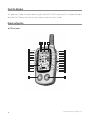
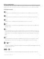
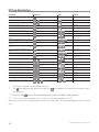
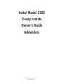
Avital Model 5303 2-way remote Owner’s Guide Addendum © 2008 Directed Electronics, Vista, CA ADG5303L 2008-07 Contents Government Regulations................................................................................................................ 3 About this addendum.................................................................................................................... 4 Remote configuration..................................................................................................................... 4 LCD 2-way remote................................................................................................................... 4 System maintenance................................................................................................................. 6 LCD 2-way remote functions........................................................................................................... 7 Standard button configuration................................................................................................... 7 Icon configuration.................................................................................................................... 8 LCD 2-way button functions.......................................................................................................... 10 LCD 2-way remote operation........................................................................................................ 11 Paging features..................................................................................................................... 11 Warn away® response description........................................................................................... 11 Triggered response description................................................................................................ 11 Setting the clock.................................................................................................................... 12 Temperature check mode........................................................................................................ 12 24-hour timer mode............................................................................................................... 12 Government Regulations This device complies with Part 15 of FCC rules. Operation is subject to the following two conditions: (1) This device may not cause harmful interference, and (2) This device must accept any interference received, including interference that may cause undesirable operation. This equipment has been tested and found to comply with the limits for a class B digital device, pursuant to Part 15 of the FCC Rules. These limits are designed to provide reasonable protection against harmful interference in a residential installation. This equipment generates and can radiate radio frequency energy and, if not installed and used in accordance with the instruction manual, may cause harmful interference to radio communications. However, there is no guarantee that interference will not occur in a particular installation. If this equipment does cause harmful interference to radio or television, which can be determined by turning the equipment OFF and ON, the user is encouraged to try to correct the interference by one or more of the following measures: • Reorient or relocate the receiving antenna. • Increase the separation between the equipment and receiver. • Connect the equipment into an outlet on a circuit different from that to which the receiver is connected. • Consult the dealer or an experienced radio / TV technician for help. This device complies with the Industry Canada Radio Standards Specification RSS 210. Its use is authorized only on a no-interference, no-protection basis; in other words, this device must not be used if it is determined that it causes harmful interference to services authorized by IC. In addition, the user of this device must accept any radio interference that may be received, even if this interference could affect the operation of the device. Warning: Changes or modifications not expressly approved by the party responsible for compliance could void the user’s authority to operate this device. © 2008 Directed Electronics. All rights reserved. 3 About this addendum This guide only includes information about using the Avital 5303’s LCD 2-way remote. For complete information about the 5303 Remote Start Security system, please consult the Owners Guide. Remote configuration ➤ LCD 2-way remote 4 5 6 7 8 9 3 2 1 31 30 29 28 10 27 11 26 25 12 24 13 23 14 22 15 21 20 16 17 4 19 18 © 2008 Directed Electronics. All rights reserved. 1 Vehicle Interior Temperature Indicator 2 Numeric Display 3 AM/PM Indicator 4 Alarm Clock Mode Indicator 5 Timer Function Indicator 6 Transmit Range Indicator 7 Transmission Indication 8 Vibrate/Beep Mode Indicator 9 Power Saver Mode Indicator 10 Remote Start Timer Mode Indicator 11 No Function 12 Vehicle Page Mode Indicator 13 Full Trigger Shock Sensor Indicator 14 Hood/Trunk Open or Trigger Indicator 15 Parking Light Indicator 16 Door Open or Trigger Indicator 17 Arm/Lock Button 18 Disarm/Unlock Button 19 Remote Start Indicator 20 Hood/Trunk Open or Trigger Indicator 21 Remote Start Button 22 Valet® Mode Indicator 23 Remote Start Safety Shutdown Indicator 24 Battery Level Indicator 25 Auxiliary Button 26 Temperature-Controlled Remote Start Indicator 27 Silent Arm/Disarm Mode Indicator 28 Full Trigger Alert Indicator 29 Arm/Disarm Indicator 30 Function Button 31 Celsius/Fahrenheit Indicator © 2008 Directed Electronics. All rights reserved. 5 ➤ System maintenance The system requires no specific maintenance other than battery replacement for the remote. LCD 2-Way Remote Battery Replacement The 2-way remote is powered by a 1.5V AAA battery. The Battery indicator has three levels that serve as a visual indication of battery charge. When the battery reaches a low charge level that requires replacement, the remote will generate a single notification chirp, and the Battery Level indicator will flash continuously. To replace the battery, gently pull the battery cover release tab, then slide the door down to expose the battery and remove the expired battery. Place the new battery into the remote observing the correct polarity. When power is returned to the remote the all icons on the remote LCD are illuminated and the remote generates all beeper tones once. 6 © 2008 Directed Electronics. All rights reserved. LCD 2-way remote functions The remote buttons are used to send commands to the system. The descriptions below reflect the standard configuration for this system. The buttons can be custom configured for the user’s specific needs by the installer. ➤ Standard button configuration Button The System Arm/Lock and Multi-Level Security Arming functions are controlled by pressing this button. ������� Button The System Disarm/Unlock and High Security Disarm functions are controlled by pressing this button. ������� Button ������� Channel 2 output is controlled by pressing and holding this button for two seconds. Button The panic feature is controlled by pressing and holding this button for three seconds. Press again to disable panic mode. ������� ������� Button The LCD backlighting will turn on when pressed for less than one second; when held for more than five seconds the remote will enter adjustment mode allowing the setting of the clock, timer mode, and audible melody selection. For more information, please refer to the Function Button Configurations section of this guide. Button The remote start function of the system is controlled by pressing this button for one second. To stop the remote start press this button once. Also, stepping on the brake pedal will cancel the remote start. and Buttons When pressed simultaneously these buttons activate 24 hour remote start timer mode, engaging the remote ������� start function every 24 hours. and ������� Buttons When pressed simultaneously these buttons display the internal temperature of the vehicle on the LCD. ������� © 2008 Directed Electronics. All rights reserved. 7 ������� and ������� Buttons The numeric display toggles between the time of the day and the alarm clock when these buttons are pressed simultaneously. ������� and Buttons Press these buttons simultaneously to activate the parking timer. Each additional press will toggle through the available options (10 min., 20 min., 30 min., 1 hour, 1.5 hours, 2 hours, and off). ������� and Buttons When pressed simultaneously these buttons toggle between beep notification and vibrate notification. ������� ������� and Buttons When pressed simultaneously these buttons activate battery saver mode. The power consumption on the remote ������� battery drops to zero when the alarm is inactive or disarmed. ➤ Icon descriptions The vehicle interior temperature icon displays the temperature of the inside of the vehicle when prompted. The numeric display icon will show the hours and minutes. The AM/PM icon indicates the time before or after noon. The alarm clock mode icon indicates that the alarm clock mode is active. The timer function icon flashes during timed functions including parking timer. The transmit range indicator icon stays visible as long as the system is within operating range. The remote transmission indicator icon displays when the transceiver is transmitting a signal. The vibrate/beep mode icon appears when the remote is set to vibrate mode. The power saver mode can be turned on or off with the remote. This icon displays the status. 8 © 2008 Directed Electronics. All rights reserved. The remote start timer mode icon indicates that the 24-hour Auto start feature is active. It automatically remote starts 24 hours from the time activated. The VRS mode icon has no function. The vehicle page mode icon displays when the alarm module is paging the remote. Page mode is activated when the valet switch in the vehicle is pressed and held for 4 seconds. The full trigger shock sensor icon indicates that the shock sensor has been triggered by a hard shock. and The hood/trunk open or trigger icon illuminates when the hood or trunk trigger has been activated or the hood or trunk is open, and bypasses those zones until it is closed. The parking light icon will flash twice when armed or disarmed. The icon also flashes during WarnAway and at the beginning and end of remote start cycles. The door open or trigger icon illuminates when the door trigger has been activated or the door is open, and bypasses that zone until it is closed. The remote start icon indicates when the vehicle is remotely started. The Valet® mode icon appears when the system is in Valet® mode. The remote start safety shut down icon indicates the vehicle may be in gear or other unsafe condition inhibiting remote start operation. The battery level icon indicates the level of power remaining in the battery. The silent arm/disarm icon appears when the system has been armed or disarmed in the silent mode. The full trigger alert icon illuminates when the security system has been triggered by a heavy impact, door trigger violation, optional sensor violation, or a hood/trunk trigger. The arm icon appears when the vehicle is armed and locked. The disarm icon appears when the vehicle is disarmed and unlocked. Celsius/Fahrenheit icon indicates the current mode of the displayed temperature either in Celsius or Fahrenheit. © 2008 Directed Electronics. All rights reserved. 9 LCD 2-way button functions Function ������� Lamp On (10 sec) Button (s) Icon Audio ������� Power Saver Mode ������� + ������� + Beep/Vibrate Mode Time Adjust Mode (hour)** 4 Vibrations/ 1 Beep 2 beeps + for 5 secs. ������� Time Adjust Mode (min) ** Melody ������� ������� ������� Alarm Clock Set Mode (hour)** 1 Time*** 2 Times** ������� Alarm Clock Set Mode (min)** 3 Times ������� Alarm Clock Music or Power on Music Selection Alarm Clock Adjust Mode (on/off)** 5 Selections 1/2/3/4/5 4 Times*** ������� 5 Times*** ������� Timer Count Down Adjust Mode (hour)** Timer Count Down Adjust Mode (min)** Timer Count Down Ending Melody Selection 1** RS Timer Count Down Mode (on/off) 6 Times*** ������� 7 Times*** ������� 5 Selections 1/2/3/4/5 8 Times*** ������� 9 Times*** ������� Remote Start On Melody Selection 2 5 Selections 1/2/3/4/5 Melody 10 Times*** ������� 10 Min Parking Count Down Mode + ������� 20 Min Parking Count Down Mode ������� 30 Min Parking Count Down Mode ������� 60 Min Parking Count Down Mode ������� 90 Min Parking Count Down Mode ������� 120 Min Parking Count Down Mode ������� Parking Count Down Off Mode ������� Alarm Clock Mode On/Off*** ������� ������� Celsius/Fahrenheit Select Mode * ������� 1 Time + 2 Times + 3 Times + 4 Times + 5 Times + 6 Times + 7 Times Melody Melody Melody Melody Melody Melody Melody + + + Melody or This function operates in the disarmed state only. ** The ������� button advances the selection upward. The button advances the selection downward or select the off setting. ������� *** Be sure to hold down for 5 seconds before entering time clock adjust mode operation. **** Press once to have the alarm clock on. Press twice to have the alarm clock off. The remote will revert to normal operation from the set mode when 15-seconds has elapsed without a button entry. 10 © 2008 Directed Electronics. All rights reserved. LCD 2-way remote operation The remote start system operates at 434 MHz and incorporates Directed’s proprietary A.S.K. out-board two-way remote. The high frequency combined with Binary Data communication achieves superior range with two-way communication. ➤ Paging features The control module sends a page to the remote as confirmation of a received command, or alarm system status. When the remote receives a page a notification, it beeps or vibrates and the alarm status, armed or disarmed, (the lock or unlock icon) appears on the LCD. If the alarm has been triggered, the remote LC displays the zone triggered. To clear the alarm page, press any button on the remote. The LCD information is also cleared. Note: You will not be able to send a command, until the alarm page is cleared. ➤ Warn away® response description A Warn Away® Response consists of an alarm page along with the responses described below. • Shock Sensor - Light impacts to the vehicle will flash the vehicle lights and chirp the siren for a few seconds. • Remote Control Notification - Ten quick beeps (or one vibration). • Remote Control LCD - The full trigger alert icon (28) will dimly illuminate for two seconds • The remote will enter Page Recognition Mode and operate alarm page alerts. Note: Icons 13 and 14 represent alarm system zone inputs. For more information about icons and the zones they represent refer to the Standard Remote Configurations section. ➤ Triggered response description A Triggered Response can be activated by any of the triggers listed below and consists of an alarm page along with the response described for each trigger. The default Triggered Response duration is 30 seconds but can be programmed from 1-180 seconds by your installer with the Directed Bitwriter®. • Sensor Trigger - Heavy impacts to the vehicle will instantly sound the siren and flash the lights for the programmed duration and report Zone 2. • Door Trigger - If a door is opened the siren will chirp for three seconds, then the siren will sound and the lights will flash for the programmed duration and report Zone 3. The three seconds allow the user time to disarm the system with a minimum of noise should a door be opened inadvertently while the system is armed. © 2008 Directed Electronics. All rights reserved. 11 • Hood Trigger - Opening the hood will sound the siren, flash the lights for the programmed duration, and report Zone 1. • Trunk Trigger - Opening the trunk (if connected) will instantly sound the siren and flash the lights for the programmed duration and report Zone 4. • Ignition Trigger - If the ignition is turned on the siren will chirp for three seconds, then the siren will sound and the lights will flash for the programmed duration and report Zone 5. When a Triggered Response is activated the transceiver will: • Repeat four quick beeps (or vibrate) for 15 seconds. • The full trigger alert icon (28) will turn on for 15 seconds. ➤ Setting the clock ������� To set the clock press and hold for five seconds, the transceiver will chirp twice and the hour selection will start flashing. Immediately press to advance the hour selection or ������� to reverse the hour selection. ������� Once the correct hour is displayed press advance the minute selection or again and the minute selection will start flashing. Then press ������� to to reverse the minute selection. Once the correct time is displayed simply stop pressing all buttons for 15 seconds and the transceiver will automatically exit the clock mode. ➤ Temperature check mode This system will report the interior temperature of your vehicle with the press of three buttons. To activate the temperature display press , and simultaneously and then release. You will hear a melody and the interior temperature will appear on the LCD screen for five seconds. ������� ������� Note: If the ignition is on, the temperature check will not work. ➤ 24-hour timer mode To enter 24 hour timer mode, press and simultaneously. The 2-way remote will produce a melody and the clock indicator will appear on the remote’s LCD. Once in Timer Mode, the system will remote start every 24 hours. Repeat this procedure to turn 24 hour Timer Mode off. ������� 12 © 2008 Directed Electronics. All rights reserved. The company behind this system is Directed Electronics Since its inception, Directed Electronics has had one purpose, to provide consumers with the finest vehicle security and car stereo products and accessories available. The recipient of nearly 100 patents and Innovations Awards in the field of advanced electronic technology. Directed is ISO 9001 registered. Quality Directed Electronics products are sold and serviced throughout North America and around the world. Call (800) 274-0200 for more information about our products and services. ADG5303L 2008-07 Vista, CA 92081 www.directed.com © 2008 Directed Electronics—All rights reserved