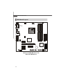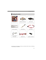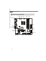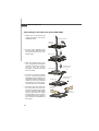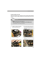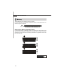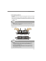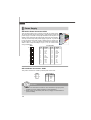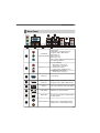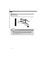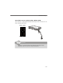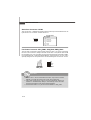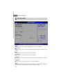
1
Media Live DIVA
MS-7411 (V1.X) Mainboard
G52-74111X2
i
Copyright Notice
T he material in this doc ument is the intellec tual property of M ICRO-STAR
INTERNATIONAL. We take every care in the preparation of this document, but no
guarantee is given as to the correctness of its contents. Our products are under
continual improvement and we reserve the right to make changes without notice.
Trademarks
All trademarks are the properties of their respective owners.
Intel® and Pentium® are registered trademarks of Intel Corporation.
AMD, Athlon™, Athlon™ XP, Thoroughbred™, and Duron™ are registered trademarks of AMD Corporation.
NVIDIA, the NVIDIA logo, DualNet, and nForce are registered trademarks or trademarks of NVIDIA Corporation in the United States and/or other countries.
PS/2 and OS ® /2 are registered trademarks of International Business Machines
Corporation.
W indows ® 95/98/2000/NT/XP are registered trademarks of Microsoft Corporation.
Netware® is a registered trademark of Novell, Inc.
Award® is a registered trademark of Phoenix Technologies Ltd.
AMI® is a registered trademark of American Megatrends Inc.
Revision History
Revision
Revision History
Date
V1.1
First Release
November 2008
Technical Support
If a problem arises with your system and no solution can be obtained from the user’s
manual, please contact your place of purchase or local distributor. Alternatively,
please try the following help resources for further guidance.
Vis i t the MSI webs ite at http ://glob al.msi. com.tw /index. php?
func=service for FAQ, technical guide, BIOS updates, driver updates, and
other information.
Contact our technical staff at http://ocss.msi.com.tw.
ii
Safety Instructions
1.
Always read the safety instructions carefully.
2.
Keep this User’s Manual for future reference.
3.
Keep this equipment away from humidity.
4.
Lay this equipment on a reliable flat surface before setting it up.
5.
The openings on the enclosure are for air convection hence protects the equipment from overheating. DO NOT COVER THE OPENINGS.
6.
Make sure the voltage of the power source and adjust properly 110/220V before connecting the equipment to the power inlet.
7.
Place the power cord such a way that people can not step on it. Do not place
anything over the power cord.
8.
Always Unplug the Power Cord before inserting any add-on card or module.
9.
All cautions and warnings on the equipment should be noted.
10. Never pour any liquid into the opening that could damage or cause electrical
shock.
11. If any of the following situations arises, get the equipment checked by service
personnel:
The power cord or plug is damaged.
Liquid has penetrated into the equipment.
The equipment has been exposed to moisture.
The equipment does not work well or you can not get it work according to
User’s Manual.
The equipment has dropped and damaged.
The equipment has obvious sign of breakage.
12. DO NOT LEAVE THIS EQUIPMENT IN AN ENVIRONMENT UNCONDITIONED, STORAGE TEMPERATURE ABOVE 600 C (1400F), IT MAY DAMAGE THE EQUIPMENT.
CAUTION: Danger of explosion if battery is incorrectly replaced.
Replace only with the same or equivalent type recommended by
the manufacturer.
iii
FCC-B Radio Frequency Interference Statement
T h is eq uip men t h as been
tested and found to c omply
with the limits for a Class B
digital device, pursuant to Part
15 of the FCC Rules. These limits are designed to provide reasonable protection
against harmful interference in a residential installation. This equipment generates,
uses and can radiate radio frequency energy and, if not installed and used in accordance with the instructions, may cause harmful interference to radio communications.
However, there is no guarantee that interference will not occur in a particular
installation. If this equipment does cause harmful interference to radio or television
reception, which can be determined by turning the equipment off and on, the user is
encouraged to try to correct the interference by one or more of the measures listed
below.
Reorient or relocate the receiving antenna.
Increase the separation between the equipment and receiver.
Connect the equipment into an outlet on a circuit different from that to
which the receiver is connected.
Consult the dealer or an experienced radio/television technician for help.
Notice 1
The changes or modifications not expressly approved by the party responsible for
compliance could void the user’s authority to operate the equipment.
Notice 2
Shielded interface cables and A.C. power cord, if any, must be used in order to
comply with the emission limits.
VOIR LA NOTICE D’INSTALLATION AVANT DE RACCORDER AU RESEAU.
Micro-Star International
MS-7411
This device complies with Part 15 of the FCC Rules. Operation is subject to the
following two conditions:
(1) this device may not cause harmful interference, and
(2) this device must accept any interference received, including interference that
may cause undesired operation.
iv
WEEE (Waste Electrical and Electronic Equipment) Statement
v
vi
vii
CONTENTS
Copyright Notice....................................................................................................ii
Trademarks.............................................................................................................ii
Revision History.....................................................................................................ii
Technical Support..................................................................................................ii
Safety Instructions................................................................................................iii
FCC-B Radio Frequency Interference Statement............................................iv
WEEE (Waste Electrical and Electronic Equipment) Statement........................v
Chapter 1 Getting Started.................................................................................1-1
Mainboard Specifications................................................................................1-2
Mainboard Layout...........................................................................................1-4
Packing Checklist............................................................................................1-5
Chapter 2 Hardware Setup...............................................................................2-1
Quick Components Guide...............................................................................2-2
CPU (Central Processing Unit)........................................................................2-3
Memory............................................................................................................2-6
Power Supply.................................................................................................2-8
Back Panel......................................................................................................2-9
Connector........................................................................................................2-10
Jumper.............................................................................................................2-16
Slot..................................................................................................................2-17
Chapter 3 BIOS Setup.........................................................................................3-1
Entering Setup.................................................................................................3-2
The Menu Bar.................................................................................................3-4
Main.................................................................................................................3-5
Advanced........................................................................................................3-6
Boot.................................................................................................................3-18
Security...........................................................................................................3-21
Chipset............................................................................................................3-22
Power..............................................................................................................3-26
Exit...................................................................................................................3-28
Appendix A Realtek ALC888 Audio.................................................................A-1
Installing the Realtek HD Audio Driver.............................................................A-2
Software Configuration..................................................................................A-4
Appendix B SATA RAID.......................................................................................B-1
RAID Configuration.........................................................................................B-2
viii
Getting Started
Chapter 1
Getting Started
Thank you for choosing the Media Live DIVA (MS-7411
V1.X) Micro-ATX mainboard. The Media Live DIVA is
based on AMD ® RS780M & SB700 chipsets for optimal
system efficiency. Designed to fit the advanced AMD ®
PhenomTM , AthlonTM 64/ 64 FX/ 64 X2 and SempronTM
processors in the socket AM2/ AM2+ package, the Media
Live DIVA delivers a high performance and professional
desktop platform solution.
1-1
MS-7411 Mainboard
Mainboard Specifications
Processor
- Supports AMD® Phenom TM, AthlonTM 64/ 64 FX/ 64 X2 and SempronT M
processors in the socket AM2/ AM2+ package (TDP Max 95 W )
(For the latest information about CPU, please visit
http://global.msi.com.tw/index.php?func=cpuform)
FSB
- Hyper Transport supports speed up to 1.0 GHz (HT1)
- Hyper Transport supports speed up to 2.6 GHz (HT3)
Chipset
- North Bridge: AMD® RS780M chipset
- South Bridge: AMD® SB700 chipset
Memory
- DDR2 400/ 533/ 667/ 800 SDRAM (240-Pin/ 1.8 V)
- 4 DDR2 DIMM slots (8GB Max) (Non-ECC)
(For more information on compatible components, please visit
http://global.msi.com.tw/index.php?func=testreport)
LAN
- Supports Gigabit Ethernet Controller for PCI ExpressTM Applications
by Realtek® RTL8111C
IEEE 1394
- Chip integrated by JMicron® JMB381
- Transfer rate is up to 400 Mb/s
Audio
- Chip integrated by Realtek® ALC888
- Compliant with Azalia 1.0 spec
IDE
- 1 IDE port by AMD® SB700
- Supports two IDE devices
- Supports Ultra DMA 33/ 66/ 100/ 133 mode
- Supports PIO, Bus Master operation mode
SATA
- 4 SATAII ports by AMD® SB700
- Supports 4 SATA devices
- Supports storage and data transfers up to 3 Gb/s
RAID
- SATA1~4 support RAID 0/ 1/ 10 m ode by AMD® SB700
1-2
Getting Started
Connector
Back Panel
- 1 VGA port
- 4 USB ports
- 1 HDMI port
- 1 IEEE 1394 port
- 1 LAN jack
- 5 audio RCA-in/ out jacks
- 3 com ponent video-out jacks
- 2 coaxial S/PDIF-in/ out jacks
On-Board Pinheader/ Connector
- 1 CD-in connector
- 1 serial port connector
- 4 USB pinheaders
- 1 IEEE 1394 pinheader
- 1 front panel audio pinheader
- 1 CIR connector
Slot
- 1 PCI express x16 slot (For VGA card use only)
- 1 PCI express x4 slot (For amplifier card use only)
- 3 PCI express x1 slots
Form Factor
- Micro-ATX (24.4 cm X 24.4 cm)
Mounting
- 8 mounting holes
1-3
MS-7411 Mainboard
Mainboard Layout
JRCA1
CPU_FAN1
JCOM
CIR1
T: VGA1
B: SPDIFOUT
SPDIF IN
HDMI1
T: I1394
B: USB
T: LAN
B: USB
JRCA2
SUBOUT
BATT
+
SATA4
SATA1
SATA2
DAE3 -SOLT
SATA3
AMD
SB70 0
PCIE1 6_X1
PCIE1 _X2
DIMM4
PCIE1 _X1
DIMM3
DIMM1
JRCA3
DIMM2
IDE 1
AMD
RS780 M
SYS_FAN1
AT X 1
JPW 1
CLR_CMOS2
PCIE1 _X3
JAUD1 CD_I N
JFP1
J139 4_ 2 JUSB0
JUSB3
JUSB2 JUSB1 PW R_ FAN1
Media Live DIVA (MS-7411 V1.X)
Micro-ATX Mainboard
1-4
Getting Started
Packing Checklist
MSI Mainboard
MSI Driver/ Utility CD
User’s Guide
Back I/O Shield
Power Cable
SATA Cable
Amplifier Card
Speaker Connector
Standard Cable for
IDE Devices
* The pictures are for reference only and your packing contents may vary depending
on the model you purchased.
1-5
Hardware Setup
Chapter 2
Hardware Setup
This chapter provides you with the information about
hardware setup procedures. While doing the installation,
be careful in holding the components and follow the
installation procedures. For some components, if you
install in the wrong orientation, the components will not
work properly.
Use a grounded wrist strap before handling computer
c om ponen ts . S tatic elec tric ity m ay damage the
components.
2-1
MS-7411 Mainboard
Quick Components Guide
CPU_FAN1, CPU,
p.2-12
p.2-3
CIR1,
p.2-14
Memory,
p.2-6
JCOM,
p.2-12
Back Panel,
p.2-9
ATX1,
p.2-8
JPW1,
p.2-8
SYS_FAN1,
p.2-12
IDE1,
p.2-10
SATA1~4,
p.2-11
Slot,
p.2-17
CLR_CMOS2,
p.2-16
JAUD1, CD_IN,
p.2-13 p.2-13
2-2
J1394_2,
p.2-15
JUSB0~3, PWR_FAN1, JFP1,
p.2-12 p.2-15
p.2-14
Hardware Setup
CPU (Central Processing Unit)
The mainboard supports AMD ® PhenomTM, AthlonTM 64/ 64 FX/ 64 X2 and SempronTM
processors in the socket AM2/ AM2+ package. The socket AM2/ AM2+ offers easy
CPU installation. When you are installing the CPU, make sure the CPU has a heat sink
and a cooling fan attached on the top to prevent overheating. If you do not have the
heat sink and cooling fan, contact your dealer to purchase and install them before
turning on the computer.
For the latest information about CPU, please visit http://global.msi.com.tw/index.
php?func=cpuform
Important
Overheating
Overheating will seriously damage the CPU and system. Always
make sure the cooling fan can work properly to protect the CPU from
overheating. Make sure that you apply an even layer of thermal paste
(or thermal tape) between the CPU and the heatsink to enhance heat
dissipation.
Replacing the CPU
While replacing the CPU, always turn off the power supply or unplug
the power supply’s power cord from the grounded outlet first to ensure
the safety of CPU.
Overclocking
This mainboard is designed to support overclocking. However, please
make sure your components are able to tolerate such abnormal
setting, while doing overclocking. Any attempt to operate beyond
product specifications is not recommended. We do not guarantee
the damages or risks caused by inadequate operation or beyond
product specifications.
2-3
MS-7411 Mainboard
CPU Installation Procedures for Socket AM2/ AM2+
1. Please turn off the power and
unplug the power cord before
installing the CPU.
Open the lever
Sliding
the plate
2. Pull the lever sideways away
from the socket. Make sure that
you raise the lever up to a 90degree angle.
3. Look for the gold arrow on the
CPU. The gold arrow should point
as shown in the picture. The CPU
c a n on l y f i t i n t h e c or r e c t
orientation. Lower the CPU down
onto the socket.
4. If the CPU is correctly installed,
the pins should be completely
embedded into the socket and can
not be seen. Please note that any
violation of the correct installation
procedures may cause permanent damage to your mainboard.
5. Press the CPU down firmly into
the socket and close the lever.
As the CPU is likely to move while
the lever is being closed, always
close the lever with your fingers
pressing tightly on top of the CPU
to make sure the CPU is properly
and completely embedded into
the socket.
2-4
90 degree
Gold arrow
Correct CPU
placement
Gold arrow
O
Incorrect CPU
placement
Gold arrow
Press down
the CPU
Close
the lever
Hardware Setup
Installing CPU Cooler Set
When you are installing the CPU, make sure the CPU has a heat sink and a cooling fan
attached on the top to prevent overheating. If you do not have the heat sink and
cooling fan, contact your dealer to purchase and install them before turning on the
computer.
Important
1. Read the CPU status in BIOS (Chapter 3).
2. Mainboard photos shown in this section are for demonstration of the
CPU/ cooler installation only. The appearance of your mainboard may
vary depending on the model you purchase.
1. Position the cooling set onto the
retention mechanism. Hook one
end of the clip to hook first.
2. Then press down the other end
of the clip to fasten the cooling
set on the top of the retention
mechanism. Locate the Fix Lever
and lift up it.
Fixed Lever
3. Fasten down the lever.
4. Attach the CPU Fan cable to the
C P U f a n c on n ec t or on t h e
mainboard.
2-5
MS-7411 Mainboard
Memory
These DIMM slots are intended for memory modules.
For more information on compatible components, please visit http://global.msi.com.
tw/index.php?func=testreport
DDR2
240-pin, 1.8V
56x2=112 pin
64x2=128 pin
Dual-Channel Memory Population Rules
In Dual-Channel mode, the memory modules can transmit and receive data with two
data bus lines simultaneously. Enabling Dual-Channel mode can enhance the system
performance. Please refer to the following illustrations for population rules under
Dual-Channel mode.
DIMM1
DIMM2
DIMM3
DIMM4
DIMM1
DIMM2
DIMM3
DIMM4
DIMM1
DIMM2
DIMM3
DIMM4
Installed
Empty
2-6
Hardware Setup
Installing Memory Modules
1. The memory module has only one notch on the center and will only fit in the right
orientation.
2. Insert the memory module vertically into the DIMM slot. Then push it in until the
golden finger on the memory module is deeply inserted in the DIMM slot. The plastic
clip at each side of the DIMM slot will automatically close when the memory module
is properly seated.
Important
You can barely see the golden finger if the memory module is properly inserted in the DIMM slot.
3. Manually check if the memory module has been locked in place by the DIMM slot
clips at the sides.
Volt
Notch
Important
1. In Dual-Channel mode, make sure that you install memory modules
of the same type and density in different channel DIMM slots.
2. To enable successful system boot-up, always insert the memory
modules into the DIMM1 first.
3. Due to the chipset resource deployment, the system density will only
be detected up to 7+GB (not full 8GB) when each DIMM is installed
with a 2GB memory module.
2-7
MS-7411 Mainboard
Power Supply
ATX 24-Pin Power Connector: ATX1
This connector allows you to connect an ATX 24-pin power supply.
To connect the ATX 24-pin power supply, make sure the plug of the
power supply is inserted in the proper orientation and the pins are
aligned. Then push down the power supply firmly into the connector.
You may use the 20-pin ATX power supply as you like. If you’d like
to use the 20-pin ATX power supply, please plug your power supply along with pin 1 & pin 13 (refer to the image at the right hand).
There is also a foolproof design on pin 11, 12, 23 & 24 to avoid
wrong installation.
Pin Definition
ATX1
12
1
24
13
PIN
SIGNAL
PIN
SIGNAL
1
2
+3.3V
+3.3V
13
14
+3.3V
-12V
3
4
GND
+5V
15
16
GND
PS-ON#
5
6
GND
+5V
17
18
GND
GND
7
8
GND
PWR OK
19
20
GND
Res
9
10
5VSB
+12V
21
22
+5V
+5V
11
+12V
12
+3.3V
23
24
+5V
GND
pin 13
ATX 12V Power Connector: JPW1
This power connector is usaed to provide power to the CPU.
Pin Definition
JPW1
2
1
PIN
SIGNAL
4
3
1
GND
2
3
GND
12V
4
12V
Important
1. Make sure that all the connectors are connected to proper power
supplies to ensure stable operation of the mainboard.
2. Power supply of 350 watts (and above) is highly recommended for
system stability.
2-8
pin 12
Hardware Setup
Back Panel
1.
3.
2.
Component
Video-Out (RGB)
3 RCA jacks.
(interlaced or progressive scan)
(supports 720p, 1080i HDTV)
Red colour: Pr
Green colour: Y
Blue colour: Pb
(not all modes support DVD playback due
to content protection )
1. Front channels
Red colour: Line-out (R)
W hite colour: Line-out (L)
Audio RCA-In/ Out 2. Subwoofer channel
Purple colour: Subwoofer-out
3. Red colour: Line-in (R)
W hite colour: Line-in (L)
VGA-Out
Digital Video /
Audio-Out
USB 2.0
LAN (RJ45)
IEEE 1394
Digital Audio-Out
15-pin D-sub
HDMI (High Definition Multimedia Interface Support)
(supports 720p, 1080i, 1080p HDTV)
Four 4-pin USB 2.0 ports (High Speed)
Ethernet 10/ 100/ 100/ 1000
6-pin DV input/ output for Digital Video
or other device
Black colour: Coaxial S/PDIF Output
Orange colour: Coaxial S/PDIF Input
2-9
MS-7411 Mainboard
Connector
IDE Connector: IDE1
This connector supports IDE hard disk drives, optical disk drives and other IDE devices.
IDE1
Important
If you install two IDE devices on the same cable, you must configure
the drives separately to master/ slave mode by setting jumpers.
Refer to IDE device’s documentation supplied by the vendors for
jumper setting instructions.
2-10
Hardware Setup
Serial ATA Connector: SATA1, SATA2, SATA3, SATA4
This connector is a high-speed Serial ATA interface port. Each connector can connect to one Serial ATA device.
SATA3 SATA4
SATA2 SATA1
Important
Please do not fold the Serial ATA cable into 90-degree angle.
Otherwise, data loss may occur during transmission.
2-11
MS-7411 Mainboard
Serial Port Connector: JCOM
This connector is a 16550A high speed communications port that sends/receives 16
bytes FIFOs. You can attach a serial device to it.
Pin Definition
5
6
1
2
JCOM
PIN
SIGNAL
1
2
SOUTA
GROUND
3
4
Key (no pin)
GROUND
5
6
SINA
VCC5
Fan Power Connector: CPU_FAN1, SYS_FAN1, PWR_FAN1
The fan power connectors support system cooling fan with +12V. W hen connecting
the wire to the connectors, always note that the red wire is the positive and should
be connected to the +12V; the black wire is Ground and should be connected to GND.
If the mainboard has a System Hardware Monitor chipset onboard, you must use a
specially designed fan with speed sensor to take advantage of the CPU fan control.
CONTROL
SENSOR
+1 2V
GND
CPU_FAN1
PWR_FAN1
GND
+12V
SENSOR
Control
SYS_FAN1
Important
1. Please refer to the recommended CPU fans at processor’s official
website or consult the vendors for proper CPU cooling fan.
2. CPU_FAN1 supports fan control. You can activate the Smart Fan
function in the BIOS Setup Utility to automatically control the CPU
fan speed according to the actual CPU temperature.
3. Fan/ heatsink with 3 or 4 pins are both available for CPU_FAN1.
2-12
Hardware Setup
CD-In Connector: CD_IN
This connector is provided for exaternal audio input.
GND
L
R
CD_IN
Front Panel Audio Connector: JAUD1
This connector allows you to connect the front panel audio and is compliant with
Intel® Front Panel I/O Connectivity Design Guide.
10
9
2
1
JAUD1
Pin Definition
PIN
SIGNAL
DESCRIPTION
1
2
MIC_L
GND
Microphone - Left channel
Ground
3
4
MIC_R
PRESENCE#
Microphone - Right channel
Active low signal-signals BIOS that a High Definition Audio dongle
is connected to the analog header. PRESENCE# = 0 when a
High Definition Audio dongle is connected
5
6
LINE out_R
MIC_JD
Analog Port - Right channel
Jack detection return from front panel microphone JACK1
7
Front_JD
Jack detection sense line from the High Definition Audio CODEC
jack detection resistor network
8
9
NC
LINE out_L
No control
Analog Port - Left channel
10
LINEout_JD
Jack detection return from front panel JACK2
2-13
MS-7411 Mainboard
Front USB Connector: JUSB0, JUSB1, JUSB2, JUSB3
This connector, compliant with Intel® I/O Connectivity Design Guide, is ideal for connecting high-speed USB interface peripherals such as USB HDD, digital cameras,
MP3 players, printers, modems and the like.
Pin Definition
2
1
10
9
JUSB0/ 1/ 2/ 3
PIN
SIGNAL
PIN
SIGNAL
1
VCC
2
VCC
3
USB0-
4
USB1-
5
USB0+
6
USB1+
7
GND
8
GND
9
Key (no pin)
10
USB 2.0 Bracket
(Optional)
Important
Note that the pins of VCC and GND must be connected correctly to
avoid possible damage.
CIR Connector: CIR1
This connector allows you to connect to consumer infrared devices.
Pin Definition
1
5
CIR1
2-14
Pin
Signal
1
CIRTX
2
3
GND
CIRRX
4
5
NC
VCC5
Hardware Setup
Front Panel Connector: JFP1
This connector is provided for electrical connection to the front panel switches/LEDs
and is compliant with Intel® Front Panel I/O Connectivity Design Guide.
Pin Definition
Power Power
LED
Switch
+ -
JFP1
2
1
10
9
+ - - +
HDD Reset
LED Switch
PIN
SIGNAL
DESCRIPTION
1
2
HD_LED +
FP PWR/SLP
Hard disk LED pull-up
MSG LED pull-up
3
4
HD_LED FP PWR/SLP
Hard disk active LED
MSG LED pull-up
5
6
RST_SW PWR_SW +
Reset Switch low reference pull-down to GND
Power Switch high reference pull-up
7
8
RST_SW +
PWR_SW -
Reset Switch high reference pull-up
Power Switch low reference pull-down to GND
9
RSVD_DNU
Reserved. Do not use.
IEEE1394 Connector: J1394_2
This connector allows you to connect the IEEE1394 device via an optional IEEE1394
bracket.
Pin Definition
10
9
2
1
J1394_2
PIN
SIGNAL
PIN
SIGNAL
1
TPA+
2
TPA-
3
Ground
4
Ground
5
TPB+
6
TPB-
7
Cable power
8
Cable power
9
Key (no pin)
10
Ground
IEEE1394 Bracket
(Optional)
2-15
MS-7411 Mainboard
Jumper
Clear CMOS Jumper: CLR_CMOS2
There is a CMOS RAM onboard that has a power supply from an external battery to
keep the dasta of system configuration. W ith the CMOS RAM, the system can automatically boot OS every time it is turned on. If you want to clear the system configuration,
set the jumper to clear data.
1
CLR_CMOS2
1
3
Keep Data
1
3
Clear Data
Important
You can clear CMOS by shorting 2-3 pin while the system is off.
Then return to 1-2 pin position. Avoid clearing the CMOS while the
system is on; it will damage the mainboard.
2-16
Hardware Setup
Slot
PCI (Peripheral Component Interconnect) Express Slot
The
The
The
The
PCI
PCI
PCI
PCI
Express
Express
Express
Express
slot supports the PCI Express interface expansion card.
x16 slot supports up to 4.0 GB/s transfer rate.
x4 slot supports up to 1.0 GB/s transfer rate.
x1 slot supports up to 250 MB/s transfer rate.
PCI Express x16 Slot
(For x8 VGA card use only)
PCI Express x4 Slot
(For D2AUDIO DAE-3 amplifier card use only)
PCI Express x1 Slot
speaker connector
* We s uggest that you should connect the
speaker connector to the amplifier card first
for easy and quick installation.
Important
When adding or removing expansion cards, make sure that you
unplug the power supply first. Meanwhile, read the documentation
for the expansion card to configure any necessary hardware or software settings for the expansion card, such as jumpers, switches or
BIOS configuration.
2-17
BIOS Setup
Chapter 3
BIOS Setup
This chapter provides you with the information about
the BIOS setup program and allows you to configure
the system for optimum use. You may need to run the
setup program when:
An error message appears on the screen during the
system booting up and requests you to run SETUP.
You want to change the default settings for customized features.
3-1
MS-7411 Mainboard
Entering Setup
Power on the computer and the system will start POST (Power On Self Test) process.
W hen the message below appears on the screen, press <DEL> key to enter Setup.
Press DEL to enter SETUP
If the message disappears before you respond and you still wish to enter Setup,
restart the system by turning it OFF and On or pressing the RESET button. You may
also restart the system by simultaneously pressing <Ctrl>, <Alt> and <Delete> keys.
Important
1. The items under each BIOS category described in this chapter are
under continuous update for better system performance. Therefore,
the description may be slightly different from the latest BIOS and
should be held for reference only.
2. Upon boot-up, the 1st line appearing after the memory count is the
BIOS version. It is usually in the format:
A7411AMS V1.0 071508 where:
1st digit refers to BIOS maker as A = AMI, W = AWARD and P =
PHOENIX.
2nd - 5th digit refers to the model number.
6th digit refers to the chipset as I = INTEL, A = AMD, N = NVIDIA and V
= VIA.
7th - 8th digit refers to the customer as MS = all standard customers.
V1.0 refers to the BIOS version.
071508 refers to the date this BIOS was released.
3-2
BIOS Setup
Control Keys
<->
Move to the previous item
<¯>
Move to the next item
<¬ >
Move to the item in the left hand
<® >
Move to the item in the right hand
<Enter>
Select the item
<Esc>
Jumps to the exit menu or returns to the main menu from a submenu
<+/PU>
Increase the numeric value or make changes
<-/PD>
Decrease the numeric value or make changes
<F1>
General help
<F10>
Save all the CMOS changes and exit
Getting Help
After entering the Setup menu, the first menu you will see is the Main Menu.
M ain M enu
The main menu lists the setup functions you can make changes to. You can use the
arrow keys (-¯) to select the item. The on-line description of the highlighted setup
function is displayed at the bottom of the screen.
Sub-M enu
If you find a right pointer symbol (as shown in
the right view) appears to the left of certain
fields that means a sub-menu can be launched
from this field. A sub-menu contains additional
options for a field parameter. You can use arrow keys (-¯) to highlight the field and
press <Enter> to call up the sub-menu. Then you can use the control keys to enter
values and move from field to field within a sub-menu. If you want to return to the
main menu, just press the <Esc>.
General Help <F1>
The BIOS setup program provides a General Help screen. You can call up this screen
from any menu by simply pressing <F1>. The Help screen lists the appropriate keys
to use and the possible selections for the highlighted item. Press <Esc> to exit the
Help screen.
3-3
MS-7411 Mainboard
The Menu Bar
Main
Use this menu for basic system configurations, such as time, date etc.
Advanced
Use this menu to set up the items of special enhanced features available on your
system.
Boot
Use this menu to specify the priority of boot devices.
Security
Use this menu to set Supervisor and User Passwords.
Chipset
Use this menu to change the values in the chipset registers and optimize your system’s
performance.
Power
Use this menu to specify your settings for power management.
Exit
This menu allows you to load the BIOS default values or factory default settings into
the BIOS and exit the BIOS setup utility with or without changes.
3-4
BIOS Setup
Main
BIOS Information
This item shows the information of AMI® BIOS. (Read-only)
Processor
This item shows the information of Processor. (Read-only)
System M emory
This item shows the information of System Memory. (Read-only)
System Time
This allows you to set the system time that you want (usually the current time). The
time format is <hour> <minute> <second>.
System Date
This allows you to set the system date that you want (usually the current date). The
date format is <day> <month> <date> <year>.
[Day]
Day of the week, from Sun to Sat, determined by BIOS.
[Month]
The month from Jan. through Dec.
[Date]
The date from 1 to 31 can be keyed by numeric function keys.
[Year]
The year can be adjusted by users.
3-5
MS-7411 Mainboard
Advanced
WARNING: Setting wrong values in below sections may cause system to
malfunction.
CPU Configuration
Press <Enter> and the following sub-menu appears:
3-6
BIOS Setup
M odule Version
This item shows the version of the current USB module. (Read-only)
AGESA Version
This item shows the version of the AMD ® Generic Encapsulated Software
Architecture. (Read-only)
Physical/ Logical Count
These items show the detail CPU information. (Read-only)
AM D AthlonTM 64 X2 Dual Core Processor 4400+
Revision
This item shows the current status of the processor. (Read-only)
Cache L1/ 2/ 3
Cache memory is additional memory that is much faster than conventional
DRAM (system memory). W hen the CPU requests data, the system transfers
the requested data from the main DRAM into cache memory, for even faster
access by the CPU. This item shows the internal cache (also known as L1 or
level 1 cache) and external cache (also known as L2 or level 2 cache).
Speed
This item shows the current CPU Front Side Bus (FSB) clock speed. (Readonly)
3-7
MS-7411 Mainboard
NB Clk
This item allows you to select the NB clock.
Current/ Maximum FSB M ultiplier
These items show the current/ maximum FSB Multiplier. (Read-only)
GART Error Reporting
The GART is a device that translates a range of physical address space,
called the GART aperture, to a logical address based on page tables in system
memory. This item is used to Enable or Disable GART Error Reporting.
M icrocode Update
This item is used to Enable or Disable Update CPU Microcode.
Secure Virtual M achine M ode
This item is used to enable or disable the SVM (Secure Virtual Machine) mode.
Pow e r No w
This item allows you to enable or disable AMD ® PowerNow technology. W hen
set to Enabled, the system always operates in a conserve power mode. If you
want optimize the processor, set this item to Disabled, so that the processor’s
speed will vary depending on the use of your operating system and applications.
Default setting is set to Enabled.
3-8
BIOS Setup
IDE Configuration
Press <Enter> and the following sub-menu appears:
OnBoard PCI IDE Controller
The integrated peripheral controller contains a PCI IDE interface with support
for two IDE channels. Select [Disabled] to disable the integrated IDE controller,
[Primary] to enable only the primary IDE controller, [Secondary] to enable only
the secondary IDE controller, or [Both] to enable both IDE controllers.
Primary/ Secondary/ Third/ Fourth IDE M aster/ Slave
Press <Enter> and the following sub-menu appears:
Type
Press PgUp/ <+> or PgDn/ <-> to select [Manual], [None] or [Auto] type.
Note that the specifications of your drive must match with the drive
table. The hard disk will not work properly if you enter improper information for this category. If your hard disk drive type is not matched or
listed, you can use [Manual] to define your own drive type manually.
3-9
MS-7411 Mainboard
LBA/ Large M ode
This item allows you to enable or disable the LBA (Logical Block Address,
the logical block size in hard disk) mode.
Block (M ulti-Sector Transfer)
W hen the setting is Auto, it will read or write more sector at every circle
to enhance the hard disk performance. Setting options: [Auto], [Disabled].
PIO M ode
The PIO (Programmed Input/ Output) Mode let you set a PIO mode (0-4)
for the IDE devices that the onboard IDE interface supports. Modes 0
through 4 provide successively increased performance. In Auto mode,
the system automatically determines the best mode for each device.
The settings are: [Auto], [Mode 0], [Mode 1], [Mode 2], [Mode 3], [Mode
4].
DM A M ode
This item allows you to enable or disable the DMA (Direct Memory
Access) mode.
S.M.A.R.T
This allows you to activate the S.M.A.R.T. (Self-Monitoring Analysis &
Reporting Technology) capability for the hard disks. S.M.A.R.T is a
utility that monitors your disk status to predict hard disk failure. This
gives you an opportunity to move data from a hard disk that is going to
fail to a safe place before the hard disk becomes offline.
32Bit Data Transfer
The IDE interface in the integrated peripherals controller supports 32bit data transfers. Select [Enabled] only if your IDE hard drives can also
support 32-bit transfer mode.
3-10
BIOS Setup
SuperIO Configuration
Press <Enter> and the following sub-menu appears:
Serial Port1 Address
This item specifies the base I/O port address of the onboard Serial Port 1 (COM
A). Select [Auto] allows AMI® BIOS to automatically determine the correct base
I/O port address. Setting options: [3F8/ IRQ4], [2F8/ IRQ3], [3E8/ IRQ4], [2E8/
IRQ3] and [Disabled].
Serial Port1 M ode
This item allows you to specify the operation mode for serial port1. Setting
options: [Normal], [IrDA], [ASKIR].
[Normal]
RS-232C Serial Port
[IrDA]
IrDA-compliant Serial Infrared Port
[ASKIR]
Amplitude Shift Keyed Infrared Port
OnBoard CIR Port
This item is used to Enable or Disable OnBoard Consumer Remote Control (TV
remote IR).
Chassis Intrusion
The field enables or disables the feature of recording the chassis intrusion
status and issuing a warning message if the chassis is once opened. To clear
the warning message, set the field to [Reset]. The setting of the field will
automatically return to [Enabled] later.
3-11
MS-7411 Mainboard
Hardware Health Configuration
Press <Enter> and the following sub-menu appears:
H/W Health Function
This setting enables Hardware Health Monitoring Device.
CPU/ System/ Power FAN Mode Setting
This item allows you to specify the operation mode for CPU/ System/ Power
FAN. Setting options: [Full On mode], [Automatic mode], [PWM Manually mode].
[Full On mode]
Fan work on full speed.
[Automatic mode]
The PW M value is subject to the temperature
inputs linear changs.
[PWM Manually mode] The PW M value is subject to the value set by
user.
CPU Temperature, System Temperature1/ 2, CPU/ System/ Power Fan
Speed
These items display the current status of all of the monitored hardware devices
and components such as CPU temperature and system fan speed.
+3.30V, +5.00V, VCC, +12.0V, CPU Core
These items display the current status of all of the monitored hardware devices
and components such as CPU voltages.
3-12
BIOS Setup
ACPI Configuration
Press <Enter> and the following sub-menu appears:
General ACPI Configuration
Press <Enter> and the following sub-menu appears:
Suspend mode
Select the type of Suspend mode:
[Auto] After the period of inactivity selected in the Auto Suspend Timeout field, the system automatically enters STD
mode. If STD mode is unavailable, the system enters
STR mode.
[S1]
Save to disk
[S3]
Suspend to RAM
Report Video on S3 Resume
This item is used to Enable or Disable Report Video on S3 Resume.
Advanced ACPI Configuration
Press <Enter> and the following sub-menu appears:
3-13
MS-7411 Mainboard
ACPI Version Features
This item is used to select the ACPI Features.
ACPI APIC support
This item is used to Enable or Disable support ACPI APIC.
AMI OEMB table
This item is used to Enable or Disable AMI® OEM ACPI table.
Headless mode
This feature allows operating without a keyboard, monitor or mouse.
To run in headless mode, both BIOS and operating system must support
headless operation. W hen enabled, the BIOS will update the FACP to
indicate support for headless operation. Operating systems that support headless operation can proceed to boot in headless mode.
3-14
BIOS Setup
Event Log Configuration
Press <Enter> and the following sub-menu appears:
View Event Log
This item is used to view the Event Log which occurred during post or runtime.
M ark all events as read
This item is used to mark all events as read and they do not display at next time.
Clear Event Log
This item is used to clear all events in nvram and they do not display at next
time.
3-15
MS-7411 Mainboard
USB Configuration
Press <Enter> and the following sub-menu appears:
M odule Version - 2.24.3-13.4
USB Devices Enabled: 1 Keyboard, 1 Drive
Legacy USB Support
Set to [Enabled] if your need to use any USB 1.1/ 2.0 device in the operating
system that does not support or have any USB 1.1/ 2.0 driver installed, such
as DOS and SCO Unix. Set to [Disabled] only if you want to use any USB device
other than the USB mouse.
USB 2.0 Controller Mode
Set to [Enabled] if you need to use any USB 2.0 device in the operating system
that does not support or have any USB 2.0 driver installed, such as DOS and
SCO Unix.
BIOS EHCI Hand-Off
This is a workaround for OSes without EHCI hand-off support. The EHCI
ownership change should claim by EHCI driver.
USB Mass Storage Device Configuration
Press <Enter> and the following sub-menu appears:
3-16
BIOS Setup
USB Mass Storage Reset Delay
This option specifies amount of time the BIOS should wait after issuing
a reset to the USB mass storage devices.
Device #1 Lenovo USB Flash Drive PMAP
Emulation Type
This field allows you to enable or disable the USB Port 64/60 Emulation
function. W hen the function is enabled, the USB keyboard is allowed
to type some special combination keys.
3-17
MS-7411 Mainboard
Boot
Boot Settings Configuration
Press <Enter> and the following sub-menu appears:
Quick Boot
Setting the item to [Enabled] allows the system to boot within 5 seconds since
it will skip some check items.
Quiet Boot
If set to [enabled] the OS boots straight to the GUI without showing the POST
screen, if set to [disabled] it boots to the POST first.
3-18
BIOS Setup
Bootup Num-Lock
This setting is to set the Num Lock status when the system is powered on.
Setting to [On] will turn on the Num Lock key when the system is powered on.
Setting to [Off] will allow users to use the arrow keys on the numeric keypad.
Wait For ‘F1’ If Error
This BIOS feature controls the system's response when an error is detected
during the boot sequence. W hen enabled, the BIOS will halt the boot sequence
when an error is detected. You will need to press the F1 button at this point. It
brings you to the BIOS setup menu where you can adjust the settings to fix the
problem. W hen disabled, the BIOS will not halt the boot sequence, even when
an error is detected. The system will continue to boot into the operating system.
Boot Device Priority
Press <Enter> and the following sub-menu appears:
1st/ 2nd Boot Device
These items allow you to set the s equence of boot devices where BIOS
attempts to load the operating system.
Hard Disk Drives
Press <Enter> and the following sub-menu appears:
1st Drive
This item allows you to set the type of hard disk drives installed.
3-19
MS-7411 Mainboard
Removable Drives
Press <Enter> and the following sub-menu appears:
1st Drive
This item allows you to set the type of removable drives installed.
3-20
BIOS Setup
Security
Supervisor Password
User Password
: Not Installed
: Not Installed
Change Superv isor Password
Use this item to change the supervisor password that controls access to the BIOS
Setup utility.
Change User Password
Use this item to change the user password that controls access to the system at
boot.
Boot Sector Virus Protection
W hen you enable this item and someone attempt to write data into this area, BIOS will
show a warning message on screen and it will alarm beep.
3-21
MS-7411 Mainboard
Chipset
NorthBridge Configuration
Press <Enter> and the following sub-menu appears:
Internal Graphics Configuration
Press <Enter> and the following sub-menu appears:
3-22
BIOS Setup
Internal Graphics M ode
The field allows you to select whether the UMA (Unified Memory
Architecture) or Sideport (Local Frame Buffer) memory allocated for
video memory.
UMA Frame Buffer Size
Frame Buffer is the video memory that stores data for video display
(frame). This field is used to determine the memory size for Frame
Buffer. Larger frame buffer size increases video performance.
SIDEPORT Clock Speed
This item is used to adjust the Side Port Memory Clock.
GFX Engine Clock Override
This item is used to adjust the GFX Engine Clock Clock.
Primary Video Controller
This item used to select the Primary Video Controller interface.
AMD 780 HD Audio
This item used to Enable or Disable the AMD ® 780M(NB) HD Audio.
3-23
MS-7411 Mainboard
SouthBridge Configuration
Press <Enter> and the following sub-menu appears:
HD Audio Azalia Device
This item is used to Enable or Disable the AMD SB700(SB) HD Audio.
OnChip SATA Channel/ Type
This setting is used to specify the SATA controller. The settings are:
[Disabled]
Disable the SATA controller.
[Auto]
PATA and SATA will be arranged by BIOS, and you
will be able to see the IDE Device status listed in Standard
COMS Features.
[Legacy Mode] PATA and SATA will be combined. Max. of 2 IDE drives
in each channel are available.
[Native IDE]
PATA and SATA will both be enabled. Max. of 6 IDE
drives are supported.
SATA IDE Combined Mode
This item is used to Enable or Disable the SATA IDE Combined Mode.
PATA Channel Config
This item is used to select the PATA Channel.
3-24
BIOS Setup
OnBoard Peripherals Configuration
Press <Enter> and the following sub-menu appears:
Realtek 8111C PCIE NIC
This item is used to Enable or Disable OnBoard LAN (Realtek® 8111C) Device.
Realtek 8111C Option ROM
This item is used to Enable or Disable OnBoard LAN (Realtek® 8111C) Option
ROM.
Onboard 1394 Controller
This setting is used to Enable or Disable the onboard IEEE 1394 controller.
3-25
MS-7411 Mainboard
Power
Power M anagement/ APM
Setting to [Enabled] will activate an Advanced Power Management (APM) device to
enhance Max Saving mode and stop CPU internal clock.
Power Button M ode
This feature allows users to configure the Power Button function. Settings are:
[Off]
The power button functions as a normal power-on/-off button.
[Suspend]
W hen you press the power button, the computer enters the
suspend/ sleep mode, but if the button is pressed for more
than four seconds, the computer is turned off.
Resume on PME
W hen setting to [Enabled], this setting allows your system to be awakened from the
power saving modes through any event on PME (Power Management Event).
RTC Resume
W hen [Enabled], your can set the date and time at which the RTC (real-time clock)
alarm awakens the system from Suspend mode.
3-26
BIOS Setup
Restore on AC Power Loss
This setting specifies whether your system will reboot after a power failure or
interrupt occurs. Available settings are:
[Off]
Leaves the computer in the power off state.
[On]
Leaves the computer in the power on state.
[Last State]
Restores the system to the previous status before power
failure or interrupt occurred.
3-27
MS-7411 Mainboard
Exit
Save Changes and Exit
Save changes to CMOS and exit setup.
Discard Changes and Exit
Abandon all changes and exit setup.
Discard Changes
Abandon all changes.
Load Optimal Defaults
Use this menu to load the default values set by the mainboard manufacturer specifically for optimal performance of the mainboard.
Load Failsafe Defaults
Us e this menu to load the def ault values set by the BIOS vendor for stable
systemperformance.
3-28
Appendix A
Realtek ALC888 Audio
The Realtek ALC888 provides 10-channel DAC that simultaneously supports 7.1 sound playback and 2 channels of independent s tereo s ound output (multiple
streaming) through the Front-Out-Left and Front-OutRight channels.
MS-7411 Mainboard
Installing the Realtek HD Audio Driver
You need to install the driver for Realtek ALC888 codec to function properly before
you can get access to 2-, 4-, 6-, 8- channel or 7.1+2 channel audio operations.
Follow the procedures described below to install the drivers for different operating
systems.
Installation for Windows 2000/ XP/ Vista
For W indows ® 2000, you must install W indows ® 2000 Service Pack4 or later before
installing the driver. For Windows ® XP, you must install W indows ® XP Service Pack1
or later before installing the driver.
The following illustrations are based on W indows ® XP environment and could look
slightly different if you install the drivers in different operating systems.
1. Insert the application CD into the CD-ROM drive. The setup screen will automatically appear.
2. Click Realtek HD Audio Driver.
Click here
Important
The HD Audio Configuration
software utility is under continuous update
to enhance audio applications. Hence, the program screens shown here in
this section may be slightly different from the latest software utility and shall
be held for reference only.
A-2
Realtek ALC888 Audio
3. Click Next to install the Realtek High Definition Audio Driver.
Click here
4. Click Finish to restart the system.
S el ec t t hi s
option
Click here
A-3
MS-7411 Mainboard
Software Configuration
After installing the audio driver, you are able to use the 2-, 4-, 6- or 8- channel audio
feature now. Click the audio icon
from the system tray at the lower-right corner of
the screen to activate the HD Audio Configuration. It is also available to enable the
audio driver by clicking the Realtek HD Audio M anager from the Control Panel.
Double click
A-4
Realtek ALC888 Audio
Sound Effect
Here you can select a sound effect you like from the Environment list.
Environment Simulation
You will be able to enjoy different sound experience by pulling down the arrow,
totally 23 kinds of sound effect will be shown for selection. Realtek HD Audio Sound
Manager also provides five popular settings “Stone Corridor”, “Bathroom”, “Sewer
pipe”, “Arena” and “Audio Corridor” for quick enjoyment.
You may choose the provided sound effects, and the equalizer will adjust automatically.
If you like, you may also load an equalizer setting or make an new equalizer setting to
save as an new one by using the “Load EQ Setting” and “Save Preset” button,
click “Reset EQ Setting” button to use the default value, or click “Delete EQ Setting” button to remove a preset EQ setting.
There are also other pre-set equalizer models for you to choose by clicking “Others”
under the Equalizer part.
A-5
MS-7411 Mainboard
Equalizer Selection
Equalizer frees users from default settings; users may create their owned preferred
settings by utilizing this tool.
10 bands of equalizer, ranging from 100Hz to 16KHz.
Save
The settings are saved
permanently for future
use
Reset
10 bands of equalizer
would go back to the default setting
Enable / Disable
To disable, you can temporarily s top the sound
effect without losing the
settings
Lo ad
W henever you would like to
use preload settings, simply
click this, the whole list will
be shown for your selection.
Delete
To delete the pre-saved settings which are created from previous steps.
A-6
Realtek ALC888 Audio
Frequently Used Equalizer Setting
Realtek recognizes the needs that you might have. By leveraging our long experience
at audio field, Realtek HD Audio Sound Manager provides you certain optimized equalizer settings that are frequently used for your quick enjoyment.
[How to Use It]
Other than the buttons “Pop” “Live” “Club” & “Rock” shown on the page, to pull down
the arrow in “Others”, you will find more optimized settings available to you.
Karaoke M ode
Karaoke mode brings Karaoke fun back home. Simply using the music you usually
play, Karaoke mode can help you eliminate the vocal of the song or adjust the key to
accommodate your range.
1.Vocal Cancellation: Single click on “Voice Cancellation”, the vocal of the song would
be eliminated, while the background music is still in place, and you can be that
singer!
2.Key Adjustment: Using “Up / Down Arrow” to find a key which better fits your vocal
range.
Raise the key
Remov e the
human voice
Lower the key
A-7
MS-7411 Mainboard
Mixer
In the Mixer part, you may adjust the volumes of the rear and front panels individually.
1. Adjust Volume
You can adjust the volume of the speakers that you pluged in front or rear panel by
select the Realtek HD Audio rear output or Realtek HD Audio front output
items.
Important
Before set up, please make sure the playback devices are well plugged in the
jacks on the rear or front panel. The Realtek HD Audio front output item
will appear after you pluging the speakers into the jacks on the front panel.
2. Multi-Stream Function
ALC888 supports an outstanding feature called Multi-Stream, which means you may
play different audio sources simultaneously and let them output respectively from the
indicated real panel or front panel. This feature is very helpful when 2 people are
using the same computer together for different purposes.
Click the
button and the Mixer ToolBox menu will appear. Then check the Enable
playback multi-streaming and click OK to save the setup.
Important
If you use AC97 front panel, the device have to be plugged into the jacks on
the panel before enable the multi-stream function.
A-8
Realtek ALC888 Audio
W hen you are playing the first audio source (for example: use W indows Media
Player to play DVD/VCD), the output will be played from the rear panel, which is the
default setting.
Then you must to select the Realtek HD Audio front output from the scroll list
first, and use a different program to play the second audio source (for example: use
Winamp to play MP3 files). You will find that the second audio source (MP3 music) will
come out from the Line-Out audio jack of Front Panel.
A-9
MS-7411 Mainboard
3. Playback control
Playback device
Tool
Mute
This function is to let you freely decide which ports to
output the sound. And this is essential when multistreaming playback enabled.
- Realtek HD Audio Rear Output
- Realtek HD Audio Front Output
M u te
You may choose to mute single or multiple volume controls or to completely mute
sound output.
Tool
- Show the following volume controls
This is to let you freely decide which volume control items to be displayed.
- Advanced controls
- Enable playback multi-streaming
W ith this function, you will be able to have an audio chat with your friends via
headphone (stream 1 from front panel) while still have music (stream 2 from back
panel) in play. At any given period, you can have maximum 2 streams operating
simultaneously.
A-10
Realtek ALC888 Audio
4. Recording control
Tool
Mute
Recording device
-Back Line in/Mic, Front Lin in
-Realtek HD Audio Input
M u te
You may choose to mute single or multiple volume controls or to completely mute
sound input.
Tool
- Show the following volume controls
This is to let you freely decide which volume control items to be displayed.
- Enable recording multi-streaming
Important
ALC888 allows you to record the CD, Line, Mic and Stereo Mix channels
simultaneously, frees you from mixing efforts. At any given period, you may
choose 1 of the following 4 channels to record.
A-11
MS-7411 Mainboard
Audio I/O
In this tab, you can easily configure your multi-channel audio function and speakers.
You can choose a desired multi-channel operation here.
a. Headphone for the common headphone
b. 2CH Speaker for Stereo-Speaker Output
c. 4CH Speaker for 4-Speaker Output
d. 6CH Speaker for 5.1-Speaker Output
e. 8CH Speaker for 7.1-Speaker Output
Speaker Configuration:
1. Plug the speakers in the corresponding jack.
2. Dialogue “connected device” will pop up for your selection. Please select the
device you have plugged in.
- If the device is being plugged into the correct jack, you will be able to find the icon
beside the jack changed to the one that is same as your device.
- If not correct, Realtek HD Audio Manager will guide you to plug the device into the
correct jack.
A-12
Realtek ALC888 Audio
Connector Settings
Click
to access connector settings.
Disable front panel jack detection (option)
Find no function on front panel jacks? Please check if front jacks on your system are
so-called AC’97 jacks. If so, please check this item to disable front panel jack detection.
M ute rear panel output when front headphone plugged in.
Enable auto popup dialogue, when device has been plugged in
Once this item checked, the dialog “Connected device” would automatically pop up
when device plugged in.
A-13
MS-7411 Mainboard
S/PDIF
Short for Sony/Philips Digital Interface, a standard audio file transfer format. S/PDIF
allows the transfer of digital audio signals from one device to another without having
to be converted first to an analog format. Maintaining the viability of a digital signal
prevents the quality of the signal from degrading when it is converted to analog.
Output Sampling Rate
44.1KHz: This is recommend while playing CD.
48KHz: This is recommended while playing DVD or Dolby.
96KHz: This is recommended while playing DVD-Audio.
192KHz: This is recommended while playing High quality Audio.
Output Source
Output digital audio source: The digital audio format (such as .wav, .mp3,.midi etc)
will come out through S/PDIF-Out.
A-14
Realtek ALC888 Audio
Test Speakers
You can select the speaker by clicking it to test its functionality. The one you select
will light up and make testing sound. If any speaker fails to make sound, then check
whether the cable is inserted firmly to the connector or replace the bad speakers
with good ones. Or you may click the auto test
button to test the sounds of
each speaker automatically.
Center
Front Left
Front Right
Side Right
Side Left
Rear Left
Subwoof er
Rear Right
A-15
MS-7411 Mainboard
Microphone
In this tab you may set the function of the microphone. Select the Noise Suppression to remove the possible noise during recording, or select Acoustic Echo
Cancelltion to cancel the acoustic echo druing recording.
Acoustic Echo Cancelltion prevents playback sound from being recorded by microphone together with your sound. For example, you might have chance to use
VOIP function through Internet with your friends. The voice of your friend will come
out from speakers (playback). However, the voice of your friend might also be
recorded into your microphone then go back to your friend through Internet. In that
case, your friend will hear his /her own voic e again. W ith AEC(Ac oustic Echo
Cancellation) enabled at your side, your friend can enjoy the benefit with less echo.
A-16
Realtek ALC888 Audio
3D Audio Demo
In this tab you may adjust your 3D positional audio before playing 3D audio applications like gaming. You may also select different environment to choose the most
suitable environment you like.
A-17
MS-7411 Mainboard
Information
In this tab it provides some information about this HD Audio Configuration utility,
including Audio Driver Version, DirectX Version, Audio Controller & Audio Codec. You
may also select the language of this utility by choosing from the Language list.
Also there is a selection Show icon in system tray. Switch it on and an icon
will show in the system tray. Right-click on the icon and the Audio Accessories
dialogue box will appear which provides several multimedia features for you to take
advantage of.
A-18
SATA RAID
Appendix B
SATA RAID
The Southbridge integrates SATA host controller that
supports four SATA ports and RAID function for performance and reliability.
SATA RAID provides support for RAID 0 (Striping), RAID
1 (Mirroring), RAID 0+1 (Striping & Mirroring). RAID 0
greatly improves h ard d is k I/O p erf or manc e by
concurrently striping data across multiple drives. RAID
1 makes sure data is not lost if a drive fails as data is
simultaneously written to two drives. Drives configured
for RAID Striping are said to form a RAID 0 set, while
drives configured for RAID Mirroring are said to form a
RAID 1 set. RAID 0+1 is implemented as a mirrored
array whose segments are RAID 0 arrays. RAID has
same fault tolerance as mirroring and reduces overhead
by striping. It needs at least four drives to form a RAID.
B-1
MS-7411 Mainboard
RAID Configuration
Creating and deleting RAID set and performing other RAID setting up operations are
done in the RAID BIOS. During bootup, a screen similar to the one below will appear
for about few seconds. Press <Ctrl-F> to enter the FastBuild utility.
Important
Be sure to set the SATA Mode to “RAID” in BIOS (the path is : Intergrated
Peripherals => On-Chip ATA Devices => OnChip SATA Controller) before configuting the RAID BIOS.
The Fast Build Utility menu screen will appear. The Main Menu is used to choose the
operation to be performed.
B-2
SATA RAID
View Drives Assignments
This window displays the model number, capacities and assignment of the drives
physically attached to the SATA host adapter.
B-3
MS-7411 Mainboard
Define LD (Creating RAID)
The selection of the RAID configuration should be based upon factors including
performance, data security, and the number of drives available. It is best to carefully
consider the long-term role of the system and plan the data storage strategy. RAID
sets can be created either automatically, or to allow the greatest flexibility, manually.
1. Press 2 on the Main Menu screen to enter the Define LD Menu.
2. Press the arrow keys to highlight an logical drive number you want to define
and press Enter to select it.
and press Enter to select it.
3. On the next screen, use the space key to choose a RAID mode (RAID 0/ 1/
0+1) and use the arrow key to move to the Drives Assignments window.
• Initialize logical drive, zero the disk drives. RAID 1 or 10 only.
B-4
SATA RAID
• Stripe Block Size, the default 64KB is best for most applications. RAID 0 or
10 only.
• Gigabyte Boundary, allows use of slightly smaller replacement drives.
• Cache Mode, W riteThru or W riteBack.
4. On the Drives Assignments window, use the arrow key to choose the hard
drives which you want to make part of the LD, use the space key to change
the assignment to “Y”. Then press [Ctrl+Y] to save the configuration.
5. A message will show up on the bottom, press any key to save the configuration or press [Ctrl-Y] to allocate the RAID capacity manually.
Important
1. The default capacity is the full capacity of the selected hard drives.
2. If you allocate the first LD capacity manually, you can create second LD
with remaining capacity of the selected hard drives.
B-5
MS-7411 Mainboard
6. The LD creation is done, the screen shows the LD information as below.
Press ESC key to the main screen.
7. Press ESC key to exit the utility, a message “System is going to REBOOT! Are
You Sure?” will display, answer “Y” to exit it and the system will reboot.
B-6
SATA RAID
Delete LD (Deleting RAID)
1. Select “Delete LD” on the main screen.
2. Choose a LD No you want to delete and press “Del” or “Alt+D” delete the RAID
set.
3. On the next screen, a message will display to inform you, press “Ctrl+Y” to
delete the RAID set or other key to abort it. Press “Ctrl+Y” to complete the
deletion.
B-7
MS-7411 Mainboard
Installing the RAID Driver (for bootable RAID Array)
1.
2.
After you complete the RAID BIOS setup, boot from the W indows CD, and the
W indows XP Setup program starts.
Press F6 and wait for the W indows Setup screen to appear.
Important
Please follow the instruction below to make a SATA RAID driver for yourself.
1. Insert the MSI CD into the CD-ROM drive.
2. Click the “Browse CD” on the Setup screen.
3. Copy all the contents in the :
for Windows XP driver CD
\ATI\ATIDrv\SBDrv\RAID
for Windows Vista driver CD
\ChipSet\ATI\Packages\Drivers\SBDrv\RAID\x86 and
\ChipSet\ATI\Packages\Drivers\SBDrv\RAID\x64 to a formatted floppy
disk.
4. The driver disk for RAID controller is done.
3.
Insert the floppy that contains the RAID driver,Press the “S” key to select “Specify
Additional Device”.
4. For W indows Vista:
During the Operating system installation, after selecting the location to install
Vista click on “Load Driver” button to install a third party SCSI or RAID driver.
5. W hen prompted, insert the floppy disk or media (Floppy, CD/DVD Or USB) and
press Enter.
6. You should be shown a list of available SCSI Adapters.
7. Select “ATI AHCI Compatible RAID Controller -x86 platform” when the
system is 32-bit version or “ATI AHCI Compatible RAID Controller -x64
platform” when the system is 64-bit version and then press ENTER.
8. The next screen should confirm that you have selected the ATI RAID controller.
Press ENTER again to continue.
9. You have successfully installed the ATI RAID driver, and W indows setup should
continue.
10. Leave the disk in the floppy drive until the system reboots itself. W indows setup
will need to copy the files from the floppy again after the RAID volume is formatted,
and W indows setup starts copying files.
B-8
SATA RAID
Installing the RAID Driver Under Windows
(for Non-bootable RAID Array)
1. Insert the MSI CD into the CD-ROM drive.
2. The CD will auto-run and the setup screen will appear.
3. Under the Driver tab, click on ATI System Driver. The ATI System Driver
includes RAID Driver.
4. The driver will be automatically installed.
Important
You must install the RAID driver to enable RAID.
B-9