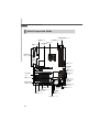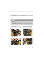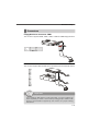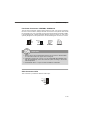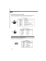
1
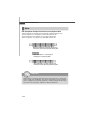
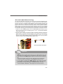
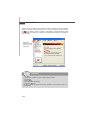
Getting Started
Chapter 1
Getting Started
Thank you for choosing the K9A2 Platinum/ K9A2 Platinum V2 Series (MS-7376 v1.X) ATX mainboards. The
K9A2 Platinum/ K9A2 Platinum V2 Series mainboards
are based on AMD® 790FX & SB600 chipsets for optimal system efficiency. Designed to fit the advanced
AM D ® Pheno m/Athlon/Se mpron proc es s ors in
socket AM2+, the K9A2 Platinum/ K9A2 Platinum V2
Series deliver a high performance and professional
desktop platform solution.
1-1
M S-7376 M ainboard
Mainboard Specifications
Processor Support
- AMD® Phenom/Athlon/Sempron in the Socket AM2+ package.
- Supports 4 pin CPU Fan Pin-Header with Fan Speed Control
(For the latest information about CPU, please visit
http://global.msi.com.tw/index.php?func=cpuform)
Supported FSB
- HyperTransport 3.0 supports speed up to 2600 MHz
Chipset
- North Bridge: AMD® 790FX chipset
- South Bridge: AMD® SB600 chipset
M emory Support
- DDR2 1066/800/667/533 DRAM (240pin/ 1.8V)
- 4 DDR2 DIMMs (8GB Max)
(For more information on compatible components, please visit
http://global.msi.com.tw/index.php?func=testreport)
LAN
- Supports 10/100/1000 Fast Ethernet by Realtek 8111B
1394 (Optional)
- Transfer rate is up to 400Mbps
- Controlled by VIA VT6308P (optional)
Audio
- Chip integrated by Realtek® ALC888/ ALC888T (optional)
- Flexible 8-channel audio with jack sensing
- Compliant with Azalia 1.0 spec
IDE
- 1 IDE port by SB600
- Supports Ultra DMA 66/100/133 mode
- Supports PIO, Bus Master operation mode
SATA
- 4 SATAII ports by SB600 (SATA1~4)
- 2 SATAII ports by Promise T3, support SAS ready device
(SATA5~6, optional)
- 2 eSATA ports by Promise T3 (optional)
- Supports storage and data transfers at up to 300MB/s
- 2 SATA (SATA5 & SATA6) ports and 2 eSATA ports by Promise T3
support to install storage devices only (optional)
Floppy
- 1 floppy port
- Supports 1 FDD with 360KB, 720KB, 1.2MB, 1.44MB and 2.88MB
1-2
Getting Started
RAID
- SATA1~4 support RAID 0/ 1/ 0+1 mode
- SATS5~6 & 2 eSATA ports support RAID0/ 1/ 0+1 mode (optional)
Connectors
Back panel
- 1 PS/2 mouse port
- 1 PS/2 keyboard port
- 1 1394 port (optional)
- 1 Optical SPDIF-out jack
- 2 eSATA ports (optional)
- 1 LAN jack
- 4 USB 2.0 ports
- 6 flexible audio jacks
On-Board Pinheaders
- 3 USB 2.0 pinheaders
- 1 1394 pinheader (optional)
- 1 Serial port pinheader (optional)
- 1 Front Panel Audio pinheader
- 1 CD-in pinheader
- 1 TPM Module pinheader (optional)
- 1 VoIP card pinheader (optional)
- 1 S/PDIF-out pinheader
TPM (optional)
- Supports TPM
Slots
- 4 PCI Express x16 slots compatible with PCIE 2.0 spec
a. the mazarine PCIE x16 slots (PCI_EX1/ PCI_EX4) support up to
PCIE 2.0x16 speed
b. for CrossFire mode, please install both graphics cards on both
mazarine PCIE x16 slots
c. the blue PCIE x16 slots (PCI_EX3/ PCI_EX5) are special design
that support up to PCIE 2.0x8 speed
d. to use all 4 PCIE x16 slots or to use both blue PCIE x16 slots,
the PCIE x 16 lanes will auto arrange from x16/ x0/ x16/ x0 to
x8/ x8/ x8/ x8
- 1 PCI Express x 1 slot
- 2 PCI slots
Form Factor
- ATX (30.5cm X 24.5 cm)
M ounting
- 9 mounting holes
1-3
M S-7376 M ainboard
Mainboard Layout
CPUFAN1
Top : mouse
Bottom:
keyboar d
1394 Port
(optional)
Optical S/PDIF Out
JPW1
ATX 1
USB ports
Top: LAN Jack
Bottom: USB ports
PCI_EX1
PCI_EX2
IDE 1
DIMM4
DIMM3
SYSFAN4
DIMM2
AMD
790FX
JPWR1
DIMM1
T: Line-In
M : Line-Out
B: Mic
T:RS- Out
M :CS-Out
B:SS-Out
SYSFAN1
Promise
T3
PCI_EX3
SATA1
SATA2 SATA3
AMD
SB600
PCI1
SATA2
LAN
Chip
PCI_EX4
SATA5 SATA6
Audio
codec
POWER
PCI2
JCD1
VIA
VT6308P
(optional)
PCI_EX5
JAUD1
JSLIC1
JFP1
BATT
+
RESET
SYSFAN3
JUSB1
JUSB2
JUSB3
FDD1 J1394_1
(optional)
K9A2 Platinum Series (MS-7376 v1.X)
ATX Mainboard
1-4
I/O
Chip
JBAT1
SPDOUT1
JFP2
SYSFAN2
JTPM
(Optional)
JCOM1
Getting Started
CPUFAN1
Top : mouse
Bottom:
keyboar d
1394 Port
(optional)
Optical S/PDIF Out
JPW1
ATX 1
USB por ts
Top: LAN Jack
Bottom: USB ports
PCI_EX1
PCI_EX2
IDE 1
DIMM4
DIMM3
SYSFAN4
DIMM2
AMD
790FX
JPWR1
DIMM1
T: Line-In
M : Line-Out
B: Mic
T:RS-Out
M :CS-Out
B:SS-Out
SYSFAN1
PCI_EX3
SATA1
SATA2 SATA3
AMD
SB600
PCI1
SATA2
LAN
Chip
PCI_EX4
JFP2
Audio
codec
POWER
PCI2
SYSFAN2
JCD1
VIA
VT6308P
(optional)
PCI_EX5
JAUD1
JSLIC1
JFP1
BATT
+
RESET
I/O
Chip
JBAT1
SPDOUT1
SYSFAN3
JUSB1
JUSB2
JUSB3
JTPM
(Optional)
JCOM1
FDD1 J1394_1
(optional)
K9A2 Platinum V2 Series (MS-7376 v1.X)
ATX Mainboard
1-5
Hardware Setup
Chapter 2
Hardware Setup
This chapter provides you with the information about
hardware setup procedures. While doing the installation,
be careful in holding the components and follow the
installation procedures. For some components, if you
install in the wrong orientation, the components will not
work properly.
Use a grounded wrist strap before handling computer
c om ponen ts . S tatic elec tric ity m ay damage the
components.
2-1
M S-7376 M ainboard
Quick Components Guide
DDR2 DIMMs, p.2-6
JPWR1, p.2-8
JPW1, p.2-8
CPUFAN1, p.2-13
CPU, p.2-3
SYSFAN4,
p.2-13
Back Panel
I/O, p.2-9
ATX1, p.2-8
SYSFAN1,
p.2-13
IDE1, p.2-11
JFP2, p.2-16
SATA1~6,
p.2-12
PCI Slots,
p.2-23
JCD1, p.2-13
JFP1, p.2-16
JTPM, p.2-14
SYSFAN2,
p.2-13
JCOM1, p.2-16
PCI Express
slots, p.2-20
FDD1, p.2-11
SPDOUT1, p.2-17
JSLIC1, p.2-15
JAUD1, p.2-14
JUSB1~3,
p.2-15
SYSFAN3,
p.2-13
POWER, p.2-19
J1394_1, p.2-17
2-2
JBAT1, p.2-18
RESET, p.2-19
Hardware Setup
CPU (Central Processing Unit)
The mainboard supports AMD ® Phenom/Athlon/Sempron processors. The mainboard
uses a CPU socket called Socket AM2+ for easy CPU installation. W hen you are
installing the CPU, make sure the CPU has a heat sink and a cooling fan
attached on the top to prevent overheating. If you do not have the heat sink and
cooling fan, contact your dealer to purchase and install them before turning on the
computer.
For the latest information about CPU, please visit http://global.msi.com.tw/index.php?
func=cpuform
Important
Overheating
Overheating will seriously damage the CPU and system. Always make sure
the cooling fan can work properly to protect the CPU from overheating. Make
sure that you apply an even layer of thermal paste (or thermal tape) between
the CPU and the heatsink to enhance heat dissipation.
Replaceing the CPU
While replacing the CPU, always turn off the ATX power supply or unplug the
power supply’s power cord from the grounded outlet first to ensure the safety
of CPU.
Overclocking
This mainboard is designed to support overclocking. However, please make
sure your components are able to tolerate such abnormal setting, while
doing overclocking. Any attempt to operate beyond product specifications is
not recommended. We do not guarantee the damages or risks caused
by inadequate operation or beyond product specifications.
2-3
M S-7376 M ainboard
CPU Installation Procedures for Socket AM2+
1. Please turn off the power and
unplug the power cord before
installing the CPU.
2. Pull the lever s ideways away
from the socket. Make sure to
raise the lever up to a 90-degree angle.
3. Look for the gold arrow on the
CPU. The gold arrow should point
as shown in the picture. The CPU
c an on l y f i t i n t h e c or r ec t
orientation.Lower the CPU down
onto the socket.
4. If the CPU is correctly installed,
the pins should be completely
embedded into the socket and
can not be seen. Please note
that any violation of the correct
in s tal lati on p roc edur es m ay
cause permanent damages to
your mainboard.
Open the lever
Sliding
the plate
90 degree
Gold arrow
Correct CPU
placement
Gold arrow
O
Incorrect CPU
placement
Gold arrow
5. Press the CPU down firmly into
the socket and close the lever.
As the CPU is likely to move while
the lever is being closed, always close the lever with your
fingers pressing tightly on top of
the CPU to make sure the CPU is
properly and completely embedded into the socket.
2-4
Press down
the CPU
Close
the lever
Hardware Setup
Installing AMD Socket AM2+ CPU Cooler Set
W hen you are installing the CPU, make sure the CPU has a heat sink and a
cooling fan attached on the top to prevent overheating. If you do not have the
heat sink and cooling fan, contact your dealer to purchase and install them before
turning on the computer.
Important
1. Read the CPU status in BIOS (Chapter 3).
2. Mainboard photos shown in this section are for demonstration of the CPU/
cooler installation only. The appearance of your mainboard may vary depending on the model you purchase.
1. Position the cooling set onto the retention mechanism.
Hook one end of the clip to hook
first.
2. Then press down the other end of
the clip to fasten the cooling set on
the top of the retention mechanism.
Locate the Fix Lever and lift up it .
Fixed Lever
3. Fasten down the lever.
4. Attach the CPU Fan cable to the CPU
fan connector on the mainboard.
2-5
M S-7376 M ainboard
Memory
These DIMM slots are used for installing memory modules.
For more information on compatible components, please visit http://global.msi.com.
tw/index.php?func=testreport
DDR2
240-pin, 1.8V
56x2=112 pin
64x2=128 pin
Dual-Channel Memory Population Rules
In Dual-Channel mode, the memory modules can transmit and receive data with two
data bus lines simultaneously. Enabling Dual-Channel mode can enhance the system
performance. Please refer to the following illustrations for population rules under
Dual-Channel mode.
1
DIMM1
DIMM2
DIMM3
DIMM4
2
DIMM1
DIMM2
DIMM3
DIMM4
3
DIMM1
DIMM2
DIMM3
DIMM4
Installed
Empty
2-6
Hardware Setup
Installing Memory Modules
1. The memory module has only one notch on the center and will only fit in the right
orientation.
2. Insert the memory module vertically into the DIMM slot. Then push it in until the
golden finger on the memory module is deeply inserted in the DIMM slot.
Important
You can barely see the golden finger if the memory module is properly inserted
in the DIMM slot.
3. The plastic clip at each side of the DIMM slot will automatically close.
Volt
Notch
Important
- DDR2 memory modules are not interchangeable with DDR and the DDR2
standard is not backwards compatible. You should always install DDR2
memory modules in the DDR2 DIMM slots.
- In Dual-Channel mode, make sure that you install memory modules of the
same type and density in different channel DIMM slots.
- To enable successful system boot-up, always insert the memory modules
into the DIM M1 first.
- Due to the chipset resource deployment, the system density will only be
detected up to 7+GB (not full 8GB) when each DIMM is installed with a 2GB
memory module.
2-7
M S-7376 M ainboard
Power Supply
ATX 24-Pin Power Connector: ATX1
This connector allows you to connect an ATX 24-pin power supply.
To connect the ATX 24-pin power supply, make sure the plug of the
power supply is inserted in the proper orientation and the pins are
aligned. Then push down the power supply firmly into the connector.
pin 13
You may use the 20-pin ATX power supply as you like. If you’d like
to use the 20-pin ATX power supply, please plug your power supply along with pin 1 & pin 13 (refer to the image at the right hand).
There is also a foolproof design on pin 11, 12, 23 & 24 to avoid
wrong installation.
pin 12
Pin Definition
24
12
ATX1
13
1
PIN
SIGNAL
PIN
SIGNAL
1
+3.3V
13
+3.3V
2
3
+3.3V
GND
14
15
-12V
GND
4
5
+5V
GND
16
17
PS-ON#
GND
6
7
+5V
GND
18
19
GND
GND
8
9
PWR OK
5VSB
20
21
Res
+5V
10
11
+12V
+12V
22
23
+5V
+5V
12
+3.3V
24
GND
ATX Power Connector: JPW1/ JPWR1
This 12V power connector JPW 1 is used to provide power to the CPU. This power
connector JPWR1 is used to provide power to stable the operation of graphics card.
JPW1 Pin Definition
JPW1
4
2
3
1
JPWR1
JPWR1 Pin Definition
PIN
SIGNAL
PIN
SIGNAL
1
2
GND
GND
1
2
NC
GND
3
4
12V
12V
3
4
GND
12V
1
Important
1. Maker sure that all the connectors are connected to proper ATX power supplies to ensure stable operation of the mainboard.
2. Power supply of 450 watts (and above) is highly recommended for system
stability.
2-8
Hardware Setup
Back Panel
LAN
Mouse
Line-In
IEEE 1394
Port (optional)
Keyboard
RS-Out
Line-Out CS-Out
Optical
eSATA Port
S/PDIF-Out (optional)
USB Port
USB Port
Mic
SS-Out
M ouse/Keyboard
The standard PS/2® mouse/keyboard DIN connector is for a PS/2® mouse/keyboard.
IEEE 1394 Port (optional)
The 1394 port on the back panel provides connection to 1394 devices.
Optical S/PDIF-Out
This SPDIF (Sony & Philips Digital Interconnect Format) connector is provided for
digital audio transmission to external speakers through an optical fiber cable.
eSATA Port (optional)
The eSATA port is for attaching the eSATA external hard drive.
USB Port
The USB (Universal Serial Bus) port is for attaching USB devices such as keyboard,
mouse, or other USB-compatible devices.
LAN
The standard RJ-45 LAN jack is for connection to
the Local Area Network (LAN). You can connect
a network cable to it.
LED
Color
LED State
Off
Left
Orange
On (steady state)
Yellow
Green / Orange
Condition
LAN link is not established.
LAN link is established.
On (brighter & pulsing) The computer is communicating with another computer on the LAN.
Green
Right
Orange
Off
10 Mbit/sec data rate is selected.
On
100 Mbit/sec data rate is selected.
On
1000 Mbit/sec data rate is selected.
2-9
M S-7376 M ainboard
Audio Ports
These audio connectors are used for audio devices. You can differentiate the color
of the audio jacks for different audio sound effects.
Line-In (Blue) - Line In, is used for external CD player, tapeplayer or other
audio devices.
Line-Out (Green) - Line Out, is a connector for speakers or headphones.
Mic (Pink) - Mic, is a connector for microphones.
RS-Out (Black) - Rear-Surround Out in 4/ 5.1/ 7.1 channel mode.
CS-Out (Orange) - Center/ Subwoofer Out in 5.1/ 7.1 channel mode.
SS-Out (Gray) - Side-Surround Out 7.1 channel mode.
2-10
Hardware Setup
Connectors
Floppy Disk Drive Connector: FDD1
This connector supports 360KB, 720KB, 1.2MB, 1.44MB or 2.88MB floppy disk drive.
FDD1
IDE Connector: IDE1
This connector supports IDE hard disk drives, optical disk drives and other IDE devices.
IDE1
Important
If you install two IDE devices on the same cable, you must configure the
drives separately to master / slave mode by setting jumpers. Refer to IDE
dev ic e’s doc umentation s upplied by the vendors for jumper s etting
instructions.
2-11
M S-7376 M ainboard
Serial ATA Connector: SATA1/ SATA2/ SATA3/ SATA4/ SATA5/ SATA6
(SATA5/ SATA6 are optinoal)
This connector is a high-speed Serial ATA interface port. Each connector can connect to one Serial ATA device.
SATA1/2/3/4 connectors are
supported by SB600
SATA1 SATA2 SATA3
SATA4 SATA5 SATA6
SATA5/6 connectors are
supported by Promise T3
(optional)
Important
Please do not fold the Serial ATA cable into 90-degree angle. Otherwise,
data loss may occur during transmission.
2-12
Hardware Setup
Fan Power Connectors: CPUFAN1, SYSFAN1~4
GND
+12V
SENSOR
Control
CPUFAN1
GND
+12V
NC
SENSOR
+1 2V
GND
SYSFAN1/2
SYSFAN4
GND
+1 2V
NC
The fan power connectors support system cooling fan with +12V. W hen connecting
the wire to the connectors, always note that the red wire is the positive and should
be connected to the +12V; the black wire is Ground and should be connected to GND.
If the mainboard has a System Hardware Monitor chipset on-board, you must use a
specially designed fan with speed sensor to take advantage of the CPU fan control.
SYSFAN3
Important
1. Please refer to the recommended CPU fans at processor’s official website
or consult the vendors for proper CPU cooling fan.
2. CPUFAN1 supports fan control. You can install Dual Core Center utility
that will automatically control the CPU fan speed according to the actual
CPU temperature.
3. Fan/heatsink with 3 or 4 pins are both available for CPUFAN1.
CD-In Connector: JCD1
This connector is provided for external audio input..
R
GND
L
JCD1
2-13
M S-7376 M ainboard
Front Panel Audio Connector: JAUD1
This connector allows you to connect the front panel audio and is compliant with
Intel® Front Panel I/O Connectivity Design Guide.
JAUD1
2
1
10
9
Pin Definition
PIN
SIGNAL
DESCRIPTION
1
2
AUD_MIC
AUD_GND
Front panel microphone input signal
Ground used by analog audio circuits
3
4
AUD_MIC_BIAS
AUD_VCC
Microphone power
Filtered +5V used by analog audio circuits
5
6
AUD_FPOUT_R
AUD_RET_R
Right channel audio signal to front panel
Right channel audio signal return from front panel
7
8
HP_ON
KEY
Reserved for future use to control headphone amplifier
No pin
9
10
AUD_FPOUT_L
AUD_RET_L
Left channel audio signal to front panel
Left channel audio signal return from front panel
TPM Module Connector: JTPM (optional)
This connector connects to a TPM (Trusted Platform Module) module (optional). Please
refer to the TPM security platform manual for more details and usages.
1
2
13
14
Pin
1
Signal
LCLK
Description
LPC clock
Pin
2
Signal
3V dual/3V_STB
Description
3V dual or 3V standby power
3
5
LRST#
LAD0
LPC reset
LPC address & data pin0
4
6
VCC3
SIRQ
3.3V power
Serial IRQ
7
9
LAD1
LAD2
LPC address & data pin1
LPC address & data pin2
8
10
VCC5
KEY
5V power
No pin
11
13
LAD3
LFRAME#
LPC address & data pin3
LPC Frame
12
14
GND
GND
Ground
Ground
2-14
Hardware Setup
Front USB Connector: JUSB1 / JUSB2 / JUSB3
This connector, compliant with Intel® I/O Connectivity Design Guide, is ideal for connecting high-speed USB interface peripherals such as USB HDD, digital cameras,
M P3 players, printers, modems and the like.
Pin Definition
JUSB1/2/3
2
1
10
9
PIN
SIGNAL
PIN
SIGNAL
1
VCC
2
VCC
3
USB0-
4
USB1-
5
USB0+
6
USB1+
7
GND
8
GND
9
Key (no pin)
10
USBOC
1394+USB Bracket
(Optional)
connect the YELLOW connector to JUSB1/2/3
Important
Note that the pins of VCC and GND must be connected correctly to avoid
possible damage.
VoIP Card Connector: JSLIC1 (optional, for ALC888T only)
This connector connects to the VoIP card. Please refer to the instruction of the VoIP
card.
JSLIC1
2
1
22
21
2-15
M S-7376 M ainboard
Front Panel Connectors: JFP1, JFP2
These connectors are for electrical connection to the front panel switches and LEDs.
The JFP1 is compliant with Intel® Front Panel I/O Connectivity Design Guide.
JFP1 Pin Definition
JFP1
10
9
Power Switch +
Power
LED
+ Reset
- Switch
- HDD
+ LED
2 1
PIN
SIGNAL
DESCRIPTION
1
HD_LED +
Hard disk LED pull-up
2
3
FP PWR/SLP
HD_LED -
MSG LED pull-up
Hard disk active LED
4
5
FP PWR/SLP
RST_SW -
MSG LED pull-up
Reset Switch low reference pull-down to GND
6
7
PWR_SW +
RST_SW +
Power Switch high reference pull-up
Reset Switch high reference pull-up
8
9
PWR_SW RSVD_DNU
Power Switch low reference pull-down to GND
Reserved. Do not use.
JFP2 Pin Definition
+
PIN
SIGNAL
JFP2
1
GND
Ground
8
2
3
SPKSLED
SpeakerSuspend LED
4
5
BUZ+
PLED
Buzzer+
Power LED
6
7
BUZNC
BuzzerNo connection
8
SPK+
Speaker+
7
+
Speaker
-
Power
LED
2
1
DESCRIPTION
Serial Port Connector: JCOM1 (optional)
This connector is a 16550A high speed communication port that sends/receives 16
bytes FIFOs. You can attach a serial device.
Pin Definition
PIN
JCOM1
2
1
2-16
9
1
2
3
4
5
6
7
8
9
SIGNAL
DESCRIPTION
DCD
SIN
SOUT
DTR
GND
DSR
RTS
CTS
RI
Data Carry Detect
Serial In or Receive Data
Serial Out or Transmit Data
Data Terminal Ready
Ground
Data Set Ready
Request To Send
Clear To Send
Ring Indicate
Hardware Setup
IEEE1394 Connector: J1394_1 (optional)
This connector allows you to connect the IEEE1394 device via an optional IEEE1394
bracket.
Pin Definition
10
9
2
1
J1394_1
PIN
SIGNAL
PIN
SIGNAL
1
TPA+
2
TPA-
3
Ground
4
Ground
5
TPB+
6
TPB-
7
Cable power
8
Cable power
9
Key (no pin)
10
Ground
1394+USB Bracket
(Optional)
connect the GREEN connector to J1394_1
S/PDIF-Out Connector: SPDOUT1
This connector is used to connect S/PDIF (Sony & Philips Digital Interconnect Format)
interface for digital audio transmission.
SPDOUT1
VCC
GND
SPDIF
S/PDIF Bracket (optional)
2-17
M S-7376 M ainboard
Jumper
Clear CMOS Jumper: JBAT1
There is a CMOS RAM onboard that has a power supply from an external battery to
keep the data of system configuration. W ith the CMOS RAM, the system can automatically boot OS every time it is turned on. If you want to clear the system configuration,
set the jumper to clear data.
1
1
3
3
1
JBAT1
Keep Data
Clear Data
Important
You can clear CMOS by shorting 2-3 pin while the system is off. Then return
to 1-2 pin position. Avoid clearing the CMOS while the system is on; it will
damage the mainboard.
2-18
Hardware Setup
Button
The motherboard provides the following buttons for you to set the computer’s function.
This section will explain how to change your motherboard’s function through the use
of button.
Power Button: POWER
This power button is used to turn-on or turn-off the system. Press the button to turnon or turn-off the system.
POWER
Reset Button: RESET
This reset button is used to reset the system. Press the button to reset the system.
RESET
2-19
M S-7376 M ainboard
Slots
PCI (Peripheral Component Interconnect) Express Slot
The PCI Express slot supports the PCI Express interface expansion card.
The PCI Express 2.0x 16 supports up to 8.0 GB/s transfer rate.
The PCI Express 2.0x 8 supports up to 4.0 GB/s transfer rate.
ssThe PCI Express x1 supports up to 250 MB/s transfer rate.
Mazarine PCI Express x16 Slots support up to
PCI Express 2.0x16 speed (PCI_EX1 & PCI_EX4)
White PCI Express x 1 Slot supports
PCI Express x1 speed (PCI_EX2)
Blue PCI Express x 16 Slots support up to
PCI Express 2.0x8 speed (PCI_EX3 & PCI_EX5)
Important
When adding or removing expansion cards, make sure that you unplug the
power supply first. Meanwhile, read the documentation for the expansion
card to configure any necessary hardware or software settings for the expansion card, such as jumpers, switches or BIOS configuration.
2-20
Hardware Setup
ATi CrossFire (Multi-GPU) Technology
ATi CrossFire (Multi-GPU) technology is an exciting new technology developed by ATI
that allows the power of multiple Graphics. CrossFire requires a CrossFire Edition
graphics card and a compatible standard Radeon (CrossFire Ready) graphics card
from the same series. To utilize this technology, always install the CrossFire Edition
graphics card in the first mazarine PCIE X16 (PCI_EX1) slot and install the CrossFire
Ready graphics card in the second mazarine PCIE X16 (PCI_EX4) slot. The mainboard
can auto detect the CrossFire mode by software, therefore you don’t have to enable
the CrossFire in BIOS by yourself. Following the process below to complete CrossFire:
1. Install the CrossFire Edition graphics card in the First mazarine PCIEx16 (PCI_EX1)
slot and install the CrossFire Ready graphics card in the Second mazarine
PCIEx16 (PCI_EX4) slot.
2. W ith two cards installed, an Cross Fire Video Link cable is required to connect the
golden fingers on the top of these two graphics cards (refer to the picture below).
Please note that although you have installed two graphics cards, only the video
outputs on the CrossFire Edition graphics card will work. Hence, you only need to
connect a monitor to the CrossFire Edition graphics card.
Cross Fire Video Link cable
Important
1. Mainboard photos shown in this section are for demonstration only. The
appearance of your mainboard may vary depending on the model you purchase.
2. If you intend to install TWO graphics cards for Cross Fire mode, make sure
that:
a. these two graphics cards are of the same brand and specifications;
b. these two cards are installed on both mazarine PCIE x16 slots.
3. If y ou intend to ins tall only O NE graphic s c ard, mak e s ure that:
a. the graphics card is Installed on first mazarine PCIE x16 slot (PCI_EX1);
4. Only Windows® XP with Service Pack 2 (SP2)& Windows ® XP Profes
-sional x64 Edition & Windows ® Vista support the CrossFire function.
2-21
M S-7376 M ainboard
3.W hen all of the hardware and software has been properly set up and installed,
reboot the system. After entering the O.S., click the “Catalyst™ Control Center”
icon
on the desktop. There is a setting in the Catalyst™ Control Center that needs
to be enabled for CrossFire™ to operate. The following aspect appears in Catalyst™
Control Center:
Select the
Advanced View
f rom t h e view
drop menu.
Important
A CrossFire™ system has four possible display modes:
• SuperTiling
• Scissor Mode
• Alternate Frame Rendering
• Super Anti-aliasing.
for more details , pleas e c ons ult the graphic s c ard manual from the
manufacturer.
2-22
Hardware Setup
PCI (Peripheral Component Interconnect) Slot
The PCI slot supports LAN card, SCSI card, USB card, and other add-on cards that
comply with PCI specifications.
32-bit PCI Slot
PCI Interrupt Request Routing
The IRQ, acronym of interrupt request line and pronounced I-R-Q, are hardware lines
over which devices can send interrupt signals to the microprocessor. The PCI IRQ
pins are typically connected to the PCI bus pins as follows:
Order 1
Order 2
Order 3
Order 4
PCI Slot 1
INT G#
INT H#
INT E#
INT F#
PCI Slot 2
INT F#
INT G#
INT H#
INT E#
Important
When adding or removing expansion cards, make sure that you unplug the
power supply first. Meanwhile, read the documentation for the expansion
card to configure any necessary hardware or software settings for the expansion card, such as jumpers, switches or BIOS configuration.
2-23
BIOS Setup
Chapter 3
BIOS Setup
This chapter provides information on the BIOS Setup
program and allows you to configure the system for
optimum use.
You may need to run the Setup program when:
² An error message appears on the screen during the
system booting up, and requests you to run SETUP.
² You want to change the default settings for customized features.
3-1
M S-7376 M ainboard
Entering Setup
Power on the computer and the system will start POST (Power On Self Test) process.
W hen the message below appears on the screen, press <DEL> key to enter Setup.
Press DEL to enter SETUP
If the message disappears before you respond and you still wish to enter Setup,
restart the system by turning it OFF and On or pressing the RESET button. You may
also restart the system by simultaneously pressing <Ctrl>, <Alt>, and <Delete> keys.
Important
1. The items under each BIOS category described in this chapter are under
continuous update for better system performance. Therefore, the description may be slightly different from the latest BIOS and should be held for
reference only.
2. Upon boot-up, the 1st line appearing after the memory count is the BIOS
version. It is usually in the format:
A7376AMS V1.2 011208 where:
1st digit refers to BIOS maker as A = AMI, W = AWARD, and P =
PHOENIX.
2nd - 5th digit refers to the model number.
6th digit refers to the chipset as I = Intel, N = nVidia, A = AMD and
V = VIA.
7th - 8th digit refers to the customer as MS = all standard customers.
V1.0 refers to the BIOS version.
011208 refers to the date this BIOS was released.
3-2
BIOS Setup
Control Keys
< ↑>
Move to the previous item
< ↓>
Move to the next item
< ←>
Move to the item in the left hand
< →>
Move to the item in the right hand
<Enter>
Select the item
<Esc>
Jumps to the Exit menu or returns to the main menu from a
submenu
<+/PU>
Increase the numeric value or make changes
<-/PD>
Decrease the numeric value or make changes
<F6>
Load Optimized Defaults
<F10>
Save configuration changes and exit setup
Getting Help
After entering the Setup menu, the first menu you will see is the Main Menu.
M ain M enu
The main menu lists the setup functions you can make changes to. You can use the
arrow keys ( ↑↓ ) to select the item. The on-line description of the highlighted setup
function is displayed at the bottom of the screen.
Sub-M enu
If you find a right pointer symbol (as shown in the
right view) appears to the left of certain fields that
means a sub-menu can be launched from this field. A
sub-menu c ontains additional options f or a field
parameter. You can use arrow keys ( ↑↓ ) to highlight the field and press <Enter> to
call up the sub-menu. Then you can use the control keys to enter values and move
from field to field within a sub-menu. If you want to return to the main menu, just press
the <Esc >.
General Help <F1>
The BIOS setup program provides a General Help screen. You can call up this screen
from any menu by simply pressing <F1>. The Help screen lists the appropriate keys
to use and the possible selections for the highlighted item. Press <Esc> to exit the
Help screen.
3-3
M S-7376 M ainboard
The Main Menu
Standard CM OS Features
Use this menu for basic system configurations, such as time, date etc.
Advanced BIOS Features
Use this menu to setup the items of AMI® special enhanced features.
Integrated Peripherals
Use this menu to specify your settings for integrated peripherals.
Power M anagement Setup
Use this menu to specify your settings for power management.
PNP/PCI Configurations
This entry appears if your system supports PnP/PCI.
H/W M onitor
This entry shows your PC health status.
Cell M enu
Use this menu to specify your settings for frequency/voltage control and overclocking.
USER SETTINGS
Use this menu to save/ load your settings to/ from CMOS for BIOS.
3-4
BIOS Setup
Load Fail-Safe Defaults
Use this menu to load the default values set by the BIOS vendor for stable system
performance.
Load Optimized Defaults
Use this menu to load the default values set by the mainboard manufacturer specifically for optimal performance of the mainboard.
BIOS Setting Password
Use this menu to set the password for BIOS.
Save & Exit Setup
Save changes to CMOS and exit setup.
Exit Without Saving
Abandon all changes and exit setup.
3-5
M S-7376 M ainboard
Standard CMOS Features
The items in Standard CMOS Features Menu includes some basic setup items. Use
the arrow keys to highlight the item and then use the <PgUp> or <PgDn> keys to select
the value you want in each item.
Date (MM:DD:YY)
This allows you to set the system to the date that you want (usually the current date).
The format is <day><month> <date> <year>.
day
Day of the week, from Sun to Sat, determined by
BIOS. Read-only.
mon th
The month from Jan. through Dec.
date
The date from 1 to 31 can be keyed by numeric function keys.
year
The year can be adjusted by users.
HH:MM:SS
This allows you to set the system time that you want (usually the current time). The
time format is <hour> <minute> <second>.
IDE Primary Master/ Slave, SATA1/ 2/ 3/ 4
Press <Enter> to enter the sub-menu, and the following screen appears.
Important
IDE Primary Master/ Slave, SATA1/ 2/ 3/ 4 are appearing when you
connect the HD devices to the IDE/ SATA connector on the mainboard.
3-6
BIOS Setup
Device/ Vender/ Size
It will showing the device information that you connected to the IDE/SATA
connector.
LBA/Large M ode
This allows you to enable or disable the LBA Mode. Setting to Auto enables LBA
mode if the device supports it and the devices is not already formatted with LBA
mode disabled.
DM A M ode
Select DMA Mode.
Hard Disk S.M.A.R.T.
This allows you to activate the S.M.A.R.T. (Self-Monitoring Analysis & Reporting
Technology) capability for the hard disks. S.M.A.R.T is a utility that monitors your
disk status to predict hard disk failure. This gives you an opportunity to move
data from a hard disk that is going to fail to a safe place before the hard disk
becomes offline.
Floppy A
This item allows you to set the type of floppy drives installed.
System Information
Press <Enter> to enter the sub-menu, and the following screen appears.
CPU Infromation/ BIOS Version/ M emory Information
These items show the CPU information, BIOS version and memory status of your
system (read only).
3-7
M S-7376 M ainboard
Advanced BIOS Features
Boot Sector Protection
W hen you enable this item and someone attempt to write data into this area, BIOS will
show a warning message on screen and it will alarm beep.
Full Screen LOGO Display
This item enables you to show the company logo on the bootup screen. Settings are:
[Enabled]
Shows a still image (logo) on the full screen at boot.
[Disabled]
Shows the POST messages at boot.
Quick Booting
Setting the item to [Enabled] allows the system to boot within 5 seconds since it will
skip some check items.
Boot Up Num Lock LED
This setting is to set the Num Lock status when the system is powered on. Setting to
[On] will turn on the Num Lock key when the system is powered on. Setting to [Off]
will allow users to use the arrow keys on the numeric keypad.
IOAPIC Function
This field is used to enable or disable the APIC (Advanced Programmable Interrupt
Controller). Due to compliance with PC2001 design guide, the system is able to run in
APIC mode. Enabling APIC mode will expand available IRQ resources for the system.
3-8
BIOS Setup
MPS Table Version
This field allows you to select which MPS (Multi-Processor Specification) version to
be used for the operating system. You need to select the MPS version supported by
your operating system. To find out which version to use, consult the vendor of your
operating system.
Chipset Feature
Press <Enter> to enter the sub-menu and the following screen appears:
HPET
The HPET (High Precision Event Timers) is a component that is part of the chipset.
You can enable it, and it will provide you with the means to get to it via the
various ACPI methods.
Port #02/03/11/12 High Speed Mode
These items are used to define the PCIE 2.0 or PCIE 1.0 mode for PCIE x16 slots.
Select “Disabled”, all the PCIE x16 slots are compatible with PCIE 1.0.
Boot Sequence
Press <Enter> to enter the sub-menu and the following screen appears:
1st/2nd/3rd Boot Device
The items allow you to set the first/ second/ third boot device where BIOS
attempts to load the disk operating system.
Boot From Other Device
Setting the option to [Yes] allows the system to try to boot from other device. if
the system fails to boot from the 1st/ 2nd/ 3rd boot device.
3-9
M S-7376 M ainboard
Integrated Peripherals
USB Controller
This setting allows you to enable/disable the onboard USB 1.1/ 2.0 controller.
USB Device Legacy Support
Select [Enabled] if you need to use a USB-interfaced device in the operating system.
Onboard LAN Controller
This setting allows you to enable/disable the onboard LAN controller.
LAN Option ROM
This item is used to decide whether to invoke the Boot ROM of the onboard LAN.
Onboard 2nd LAN Controller
This item is used to enable/disable the onboard 2nd LAN controller.
LAN Option ROM
This item is used to decide whether to invoke the Boot ROM of the 2nd LAN controller.
Onboard IEEE1394 Controller
This item allows you to enable/disable the onboard IEEE1394 controller.
3-10
BIOS Setup
Extra RAID Controller (for Promise RAID, optional)
This item allows you to enable/disable the onboard extra RAID controller.
Important
If you intend to use a extra RAID function card, you have to disable the
“Extra RAID Controller” item.
HW HD Audio Controller
This setting is used to enable/disable the HD audio controller.
On-Chip ATA Devices
Press <Enter> to enter the sub-menu:
PCI IDE BusMaster
This item allows you to enable/ disable BIOS to used PCI busmastering for
reading/ writing to IDE drives.
On-Chip SATA Controller (for SB600 RAID)
These items allow users to enable or disable the SATA controller.
SATA Mode (for SB600 RAID)
This item is used to enable/disable the RAID function for SATA devices.
I/O Devices
Press <Enter> to enter the sub-menu:
COM Port 1
This item specifies the base I/O port addresses of the onboard Serial Port.
3-11
M S-7376 M ainboard
Power Management Setup
Important
S3-related functions described in this section are available only when your
BIOS supports S3 sleep mode.
ACPI Function
This item is to activate the ACPI (Advanced Configuration and Power Management
Interface) Function. If your operating system is ACPI-aware, such as Windows 98SE/
2000/ME/ XP, select [Enabled].
ACPI Standby State
This item specifies the power saving modes for ACPI function. If your operating
system supports ACPI, such as W indows 2000/ XP , you can choose to enter the
Standby mode in S1(POS) or S3(STR) fashion through the setting of this field. Settings are:
[S1]
The S1 sleep mode is a low power state. In this state, no
system context is lost (CPU or chipset) and hardware maintains all system context.
[S3]
The S3 sleep mode is a lower power s tate where the in
formation of system configuration and open applications/files
is saved to main memory that remains powered while most
other hardware components turn off to save energy. The
information stored in memory will be used to restore the system when a “wake up” event occurs.
3-12
BIOS Setup
Suspend Time Out (M inute)
If system activity is not detected for the length of time specified in this field, all
devices except CPU will be shut off.
Power Button Function
This feature sets the function of the power button. Settings are:
[Power On/ Off]
The power button functions as normal power on/ off
button.
[Suspend]
W hen you press the power button, the computer enters the
suspend/sleep mode, but if the button is pressed for more
than four seconds, the computer is turned off.
Restore On AC Power Loss
This item specifies whether your system will reboot after a power failure or interrupt
occurs. Settings are:
[Off]
Always leaves the computer in the power off state.
[On]
Always leaves the computer in the power on state.
[Last State]
Restores the system to the status before power failure
or interrupt occurred.
Wake Up Event Setup
Press <Enter> to enter the sub-menu:
Resume From S3 By USB Device
The item allows the activity of the USB device to wake up the system from S3
(Suspend to RAM) sleep state.
Resume From S3 By PS/2 Keyboard
This controls how the PS/2 keyboard is able to power on the system. If you
choose Specific Key, the power button on the case will not function anymore
and you must type the password to power on the system.
Resume from S3 By PS/2 Mouse
This setting determines whether the system will be awakened from what power
saving modes when input signal of the PS/2 mouse is detected.
Resume by PCI Device (PME#)
W hen set to [Enabled], the feature allows your system to be awakened from the
power saving modes through any event on PME (Power Management Event).
3-13
M S-7376 M ainboard
Resume by PCIE Device
W hen set to [Enabled], the feature allows your system to be awakened from the
power saving modes through any event on PCIE device.
Resume by RTC Alarm
The field is used to enable or disable the feature of booting up the system on a
scheduled time/date.
3-14
BIOS Setup
PNP/PCI Configurations
This section describes configuring the PCI bus system and PnP (Plug & Play) feature.
PCI, or Peripheral Component Interconnect, is a system which allows I/O devices to
operate at speeds nearing the speed the CPU itself uses when communicating with
its special components. This section covers some very technical items and it is
strongly recommended that only experienced users should make any changes to the
default settings.
Primary Graphic’s Adapter
This setting specifies which graphic card is your primary graphics adapter.
PCI Latency Timer
This item controls how long each PCI device can hold the bus before another takes
over. W hen set to higher values, every PCI device can conduct transactions for a
longer time and thus improve the effective PCI bandwidth. For better PCI performance,
you should set the item to higher values.
PCI Slot 1/2 IRQ
This setting specifies IRQ for PCI devices.
3-15
M S-7376 M ainboard
IRQ Resource Setup
Press <Enter> to enter the sub-menu and the following screen appears.
IRQ 3/4/5/7/9/10/11/14/15
These items specify the bus where the specified IRQ line is used.
The settings determine if AMIBIOS should remove an IRQ from the pool of available IRQs passed to devices that are configurable by the system BIOS. The
available IRQ pool is determined by reading the ESCD NVRAM. If more IRQs must
be removed from the IRQ pool, the end user can use these settings to reserve
the IRQ by assigning an [Reserved] setting to it. Onboard I/O is configured by
AMIBIOS. All IRQs used by onboard I/O are configured as [Available]. If all IRQs
are set to [Reserved], and IRQ 14/15 are allocated to the onboard PCI IDE, IRQ 9
will still be available for PCI and PnP devices.
Important
IRQ (Interrupt Request) lines are system resources allocated to I/O devices.
When an I/O device needs to gain attention of the operating system, it signals this by causing an IRQ to occur. After receiving the signal, when the
operating system is ready, the system will interrupt itself and perform the
service required by the I/O device.
3-16
BIOS Setup
H/W Monitor
Chassis Intrusion
The field enables or disables the feature of recording the chassis intrusion status
and issuing a warning message if the chassis is once opened. To clear the warning
message, set the field to [Reset]. The setting of the field will automatically return to
[Enabled] later.
CPU Smart FAN Target
The mainboard provides the Smart Fan function which can control the CPU fan speed
automatically depending on the current temperature to keep it with in a specific range.
You can select a fan target value here. If the current CPU fan temperature reaches to
the target value, the smart fan function will be activated. It provides several sections
to speed up for cooling down automaticlly .
SYS FAN1 Control
This item allows users to select how percentage of speed for the SYS FAN1.
PC Health Status
CPU/ System Temperature, CPU FAN/ SYS FAN1/ SYS FAN2 Speed, CPU
Vcore, 3.3V, 5V, 12V, 5V SB
These items display the current status of all of the monitored hardware devices/
components such as CPU voltage, temperatures and all fans’ speeds.
3-17
M S-7376 M ainboard
Cell Menu
Important
Change these settings only if you are familiar with the chipset.
Current CPU Clock/ DRAM Frequency
These items show the current clocks of CPU and Memory frequency. Read-only.
D.O.T.3 Step 3/ 1/ 2 setting
The D.O.T.3 has 3 steps to overclock the CPU/ PCIE, you can set the overclocking
percentage for each step. W hen the CPU loading reaches to 20%, the CPU/ PCIE
frequencies will overclock according the setting of step1. W hen the CPU loading
reaches to 50%, the CPU/ PCIE frequencies will overclock according the setting of
step2. W hen the CPU loading reaches to 80%, the CPU/ PCIE frequencies will overclock
according the setting of step3.
3-18
BIOS Setup
AMD Cool’n’Quiet
The Cool’n’ Quiet technology can effectively and dynamically lower CPU speed and
power consumption.
Important
To ensure that Cool’n’Quiet function is activated and will be working properly, it is
required to double confirm that:
1. Run BIOS Setup, and select Cell Menu.
Under Cell M enu, find AM D
Cool’n’Q uiet, and s et this item to
“Enable.”
2. Enter Windows , and select [Start]->
[Settings]->[Control Pannel]->[Power
Options]. Enter Power Options Properties tag, and select Minimal Power
Management under Power schemes.
Adjust CPU FSB Frequency
This item allows you to set the CPU FSB frequency (in MHz).
Adjust CPU Ratio
This item allows you to set the CPU ratio.
Adjusted CPU Frequency
It shows the adjusted CPU frequency (FSB x Ratio). Read-only.
Advance DRAM Configuration
Press <Enter> to enter the sub-menu and the following screen appears.
3-19
M S-7376 M ainboard
DRAM Timing Mode
Setting to [Auto] enables DRAM CAS# Latency automatically to be determined by
BIOS based on the configurations on the SPD (Serial Presence Detect) EEPROM
on the DRAM module.
Bank Interleaving
This field selects 2-bank or 4-bank interleave for the installed SDRAM. Disable
the function if 16MB SDRAM is installed.
1T/2T M emory Timing
This field controls the SDRAM command rate. Selecting [1T] makes SDRAM
signal controller to run at 1T (T=clock cycles) rate. Selecting [2T] makes SDRAM
signal controller run at 2T rate.
Memory Hole at 15M Addr.
You can reserve this area of system memory for ISA adapter ROM. W hen this
area is reserved, it cannot be cached. The user information of peripherals that
need to us e this area of sys tem memory us ually discus ses their memory
requirements.
Unganged M ode support
The Unganged mode can split the available bandwidth into two distinct channels
,and this item is used to disable/ enable the unganged mode.
FSB/Memory Ratio
This item will allow you to adjust the FSB/Ratio of the memory.
Adjusted DDR M emory Frequency
It shows the adjusted DDR Memory frequency. Read-only.
Auto Disable DIM M/PCI Frequency
W hen set to [Enabled], the system will remove (turn off) clocks from empty DIMM and
PCI slots to minimize the electromagnetic interference (EMI).
CPU Voltage / M omory Voltage / NB Voltage / Hypertransport Voltage
These items dispaly the power status of CPU, Memory, FSB and chipset. Read-only.
Spread Spectrum
W hen the motherboard’s clock generator pulses, the extreme values (spikes) of the
pulses create EMI (Electromagnetic Interference). The Spread Spectrum function
reduces the EMI generated by modulating the pulses so that the spikes of the pulses
are reduced to flatter curves. If you do not have any EMI problem, leave the setting at
Disabled for optimal system stability and performance. But if you are plagued by EMI,
set to Enabled for EMI reduction. Remember to disable Spread Spectrum if you are
overclocking because even a slight jitter can introduce a temporary boost in clock
speed which may just cause your overclocked processor to lock up.
3-20
BIOS Setup
Important
1. If you do not have any EMI problem, leave the setting at [Disabled] for
optimal system stability and performance. But if you are plagued by EMI,
select the value of Spread Spectrum for EMI reduction.
2. The greater the Spread Spectrum value is, the greater the EMI is reduced,
and the system will become less stable. For the most suitable Spread
Spectrum value, please consult your local EMI regulation.
3. Remember to disable Spread Spectrum if you are overclocking because
even a slight jitter can introduce a temporary boost in clock speed which
may just cause your overclocked processor to lock up.
3-21
M S-7376 M ainboard
USER SETTINGS
Save Settings 1/ 2
These items are used to save the settings set by yourself to CMOS.
Load Settings 1/ 2
These items are available after you save your settings in Save Settings 1/ 2 items
, and are used to load the settings from CMOS.
3-22
BIOS Setup
Load Fail-Safe/ Optimized Defaults
The two options on the main menu allow users to restore all of the BIOS settings to
the default Fail-Safe or Optimized values. The Optimized Defaults are the default
values set by the mainboard manufacturer specifically for optimal performance of the
mainboard. The Fail-Safe Defaults are the default values set by the BIOS vendor for
stable system performance.
W hen you select Load Fail-Safe Defaults, a message as below appears:
Selecting Ok and pressing Y loads the BIOS default values for the most stable,
minimal system performance.
W hen you select Load Optimized Defaults, a message as below appears:
Selecting Ok and pressing Y loads the default factory settings for optimal system
performance.
3-23
M S-7376 M ainboard
BIOS Setting Password
W hen you select this function, a message as below will appear on the screen:
Type the password, up to six characters in length, and press <Enter>. The password
typed now will replace any previously set password from CMOS memory. You will
be prompted to confirm the password. Retype the password and press <Enter>. You
may also press <Esc> to abort the selection and not enter a password.
To clear a set password, just press <Enter> when you are prompted to enter the
password. A message will show up confirming the password will be disabled. Once
the password is disabled, the system will boot and you can enter Setup without
entering any password.
W hen a password has been set, you will be prompted to enter it every time you try
to enter Setup. This prevents an unauthorized person from changing any part of your
system configuration.
3-24
SATA RAID
Appendix C
SATA RAID
The SB600 and T3 (optional) integrate one SATA host
controller separately, and support RAID function for
performance and reliability.
SATA RAID provides support for RAID 0 (Striping), RAID
1 (Mirroring), RAID 0+1 (Striping & Mirroring). RAID 0
greatly improves h ard d is k I/O p erf or manc e by
concurrently striping data across multiple drives. RAID
1 makes sure data is not lost if a drive fails as data is
simultaneously written to two drives. Drives configured
for RAID Striping are said to form a RAID 0 set, while
drives configured for RAID Mirroring are said to form a
RAID 1 set. RAID 0+1 is implemented as a mirrored
array whose segments are RAID 0 arrays. RAID 0+1
has same fault tolerance as mirroring and reduces
overhead by striping. It needs at least four drives to
form a RAID 0+1.
C-1
M S-7376 M ainboard
RAID Configuration
Creating and deleting RAID set and performing other RAID setting up operations are
done in the RAID BIOS. During bootup, a screen similar to the one below will appear
for about few seconds. Press <Ctrl-F> to enter FastBuild utility.
Important
Be sure to enable the RAID function for SATA device in BIOS (please refer
the Intergrated Peripherals s ec tion in BIOS) before configuting the
Fastbuild Utility.
The FastBuild menu screen will appear. The Main Menu is used to choose the operation to be performed.
C-2
SATA RAID
View Drives Assignments
This window displays the model number, capacities and assignment of the drives
physically attached to the SATA host adapter.
Important
Please visit the MSI websit (http://www.msi.com.tw/ ) to get the Promise T3
RAID application program for more Promise RAID applications.
C-3
M S-7376 M ainboard
Define LD (Creating RAID)
The selection of the RAID configuration should be based upon factors including
performance, data security, and the number of drives available. It is best to carefully
consider the long-term role of the system and plan the data storage strategy. RAID
sets can be created either automatically, or to allow the greatest flexibility, manually.
1. Press 2 on the Main Menu screen to enter the Define LD Menu.
2. Press the arrow keys to highlight an logical drive number you want to define
and press Enter to select it.
and press Enter to select it.
3. On the next screen, use the space key to choose a RAID mode (RAID 0/ 1/
0+1) and use the arrow key to move to the Drives Assignments window.
• Initialize logical drive, zero the disk drives. RAID 1 or 10 only.
C-4
SATA RAID
• Stripe Block Size, the default 64KB is best for most applications. RAID 0 or
10 only.
• Gigabyte Boundary, allows use of slightly smaller replacement drives.
• Cache Mode, W riteThru or W riteBack.
4. On the Drives Assignments window, use the arrow key to choose the hard
drives which you want to make part of the LD, use the space key to change
the assignment to “Y”. Then press [Ctrl+Y] to save the configuration.
5. A message will show up on the bottom, press any key to save the configuration or press [Ctrl-Y] to allocate the RAID capacity manually.
Important
1. The default capacity is the full capacity of the selected hard drives.
2. If you allocate the first LD capacity manually, you can create second LD
with remaining capacity of the selected hard drives.
C-5
M S-7376 M ainboard
6. The LD creation is done, the screen shows the LD information as below.
Press ESC key to the main screen.
7. Press ESC key to exit the utility, a message “System is going to REBOOT! Are
You Sure?” will display, answer “Y” to exit it and the system will reboot.
C-6
SATA RAID
Delete LD (Deleting RAID)
1. Select “Delete LD” on the main screen.
2. Choose a LD No you want to delete and press “Del” or “Alt+D” delete the RAID
set.
3. On the next screen, a message will display to inform you, press “Ctrl+Y” to
delete the RAID set or other key to abort it. Press “Ctrl+Y” to complete the
deletion.
C-7
M S-7376 M ainboard
Installing the RAID Driver (for bootable RAID Array)
For W indows XP:
1. After you complete the RAID BIOS setup, boot from the W indows CD, and the
W indows XP Setup program starts.
2. Press F6 and wait for the W indows Setup screen to appear.
3. Insert the floppy that contains the RAID driver,Press the “S” key to select “Specify
Additional Device”.
Important
Please follow the instruction below to make a SATA RAID driver for yourself.
1. Insert the MSI CD into the CD-ROM drive.
2. Click the “Browse CD” on the Setup screen.
3. Copy all the contents in the :
* Windows XP driver CD for SB600 RAID:
\\ATI\ATIDrv\SBDrv\RAID
* Windows Vista driver CD for SB600 RAID:
\\Chipset\ATI\Packages\Drivers\SBDrv\Sb600\RAID
* Windows XP/ Vista driver CD for Promise RAID (optional):
\\IDE\Promise\FastTrak\Driver to a formatted floppy disk.
Note: for Windows Vista, you can copy the files to a medium (floppy/ CD/
DVD or USB)
4. The driver disk for RAID controller is done.
4.
5.
6.
7.
8.
9.
W hen prompted, insert the floppy disk and press Enter.
You should be shown a list of available SCSI Adapters.
Select the compatible RAID controller for 32-bit/ 64-bit version system and then
press ENTER.
The next screen should confirm that you have selected the RAID controller.
Press ENTER again to continue.
You have successfully installed the RAID driver, and W indows setup should
continue.
Leave the disk in the floppy drive until the system reboots itself. W indows setup
will need to copy the files from the floppy again after the RAID volume is formatted,
and W indows setup starts copying files.
For W indows Vista:
During the operating system installation, after selecting the location to install
W indows Vista, please click on the “Load Driver” button to load RAID driver.
Please refer the Important notice above to make a RAID Driver medium. And
then, follow the instructions to complete the whole installation.
C-8
SATA RAID
Installing the RAID Driver Under Windows
(for Non-bootable RAID Array)
1. Insert the MSI CD into the CD-ROM drive.
2. The CD will auto-run and the setup screen will appear.
3. Under the Driver tab, click on ATI System Driver or Promise PDC42819
Driver by your need. The ATI System Driver includes RAID Driver.
4. The driver will be automatically installed.
Important
You must install the RAID driver to enable RAID.
C-9