1
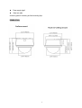
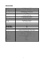
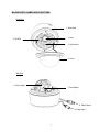
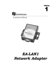
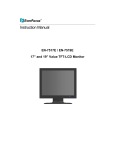
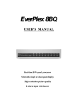
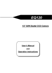
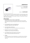
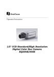
1/3” CCD Indoor 3-Axis Dual Voltage
True Day/Night IR Dome Camera
Operation Instructions
Model No.
ED335
Please read this manual first for correct installation and operation. This manual should be retained for future
reference. The information in this manual was current when published. The manufacturer reserves the right
to revise and improve its products. All specifications are therefore subject to change without notice.
PRECAUTIONS
1.
Do not install the camera near electric or magnetic fields.
Install the camera away from TV/radio transmitters, magnets, electric motors, transformers and audio
2.
speakers since the electromagnetic fields generated from these devices may distort the video image.
Never disassemble the camera beyond the recommendations in this manual nor introduce
materials other than those recommended herein.
Improper disassembly or introduction of corrosive materials may result in equipment failure or other
3.
4.
damage.
Try and avoid facing the camera toward the sun.
In some circumstances, direct sunlight may cause permanent damage to the sensor and/or internal
circuits.
Keep the power cord away from water and other liquids and never touch the power cord with
wet hands.
5.
Touching a wet power cord with the hands or touching the power cord with wet hands may result in
electric shock.
Never install the camera in areas exposed to water, oil or gas.
6.
Water, oil or gas may result in equipment failure, electric shock or, in extreme cases, fire.
Cleaning
Use a damp soft cloth to remove any dirt from the camera body. Use lens tissue or a cotton tipped
7.
applicator and ethanol to clean the camera lens. Please do not use complex solvents, corrosive or
abrasive agents for cleaning.
Do not operate the camera beyond the specified temperature, humidity or power source ratings.
Use the camera at temperatures within 0℃ ~ 40℃ (32℉~104℉) and humidity between 20~80%.
The input power source is 12VDC/24VAC.
PRODUCT OVERVIEW
ED335 is a new design IR Dome camera from Everfocus. It incorporates breakthrough DSP technology to
provide brilliant color images in well lit environments. Using a SONY Super HAD CCD image sensor, the
ED335 also delivers excellent true day/night low light performance, and equipped with 34 long lifespan/high
illumination IR LEDs the ED335 is able to deliver bright, detailed monochrome images even in low light or no
light situations out to a range of over 66 feet.
In addition, because the ED335 is easily surface or flush mounted, it can be installed in almost any indoor
environment. The 3-axis gimbal enables installers to easily mount the camera on a wall or ceiling and then
using the built in tilt and dual axis 180° twist, adjust the viewing angle and varifocal lens to frame the desired
field of view. With this unique 3-axis positioning system, installers can capture images from virtually any
angle, without compromising performance.
FEATURES
Designed with advanced digital signal processing circuitry for high image quality
520 TV lines of superior high resolution technology
True Day/night with ICR module
Equipped with 34 IR LEDs for day and night environments
IR distance up to 66 feet (20M; depending on surface reflectivity)
May be attached to wall or ceiling; flush or surface mounted
3-Axis adjustment for almost any viewing angle
Built-in vari-focal type, auto Iris lens
12VDC/24VAC Dual Voltage support
High Output IR LEDs, with a lifespan exceeding 20,000 hours
PACKAGE CONTENTS
ED335 camera, including dome/cover, camera unit and outer (surface mount) base as an assembly.
This user guide.
Accessory pack #1 containing:
4 long mounting screws
4 washers
4 plastic anchors
Hex key for cover screws
4 short screws to attach flush-mounting clips
Rubber plug for side hole in outer base.
Mounting template
1
Power supply pigtail
Video test cable
Accessory pack #2 containing two flush mounting clips
DIMENSIONS
2
SPECIFICATIONS
Pickup Device
Video Format
Scanning System
Picture Element
Horizontal Resolution
Sensitivity
Day/Night Type
S/N Ratio
Electronic Shutter
1/3” SONY Super HAD CCD
NTSC or PAL
NTSC: 525 TV lines, 60 fields/sec; PAL: 625 TV lines, 50 fields/sec.
768 x 494 (NTSC); 752 x 582 (PAL)
520 TV Lines
0 Lux (IR LED on)
0.4 Lux/F=1.2 (AGC ON)
True Day/night with ICR module
Over 48 dB (AGC off)
1/50 (1/60) ~ 1/100,000
Lens Type
Vari-focal lens, DC Auto Iris
f=2.8~10mm/f=9~22mm
Iris Level
Adjustable
Auto Gain Control
Back Light Comp.
Auto White Balance
Gamma Correction
Video Output
Sync. Mode
Power Source
Power Consumption
Dimensions
Weight
Operating Temperature
IR Distance
IR Wavelength
IR LED Lifespan
Certifications
ON
ON
ON
0.45
1. BNC 1.0Vp-p, 75 ohm
2. Additional testing video output 1.0Vp-p, 75ohm
Internal Sync.
12VDC/24VAC
12VDC: 6W max.; 24VAC: 6.5W max.
141 mm (O.D.) x 128? mm (H)/ 5.6” (O.D.) x 5.1 “(H)
0.66 kg, 1.45 lbs
0°C~40°C ; 32°F~104°F (20%~80% Humidity)
20M/66 feet
850nm
20,000 hours
CE/FCC
3
MAJOR PARTS: NAMES AND FUNCTIONS
Front View
1. Outer Base
3. Lens
2. IR LEDs
4. Light sensor
5. Cover
Side View
6. Focus Adjust
7. Zoom Adjust
8. Video Output
9. Power Input
4
Back View
Video Test Output
Iris level adjust
1. Base
The camera unit sets in the dome base, when it is shipped from the factory. This base is used
for surface mounting, and is discarded for flush mounting.
2. IR LEDs
3. Lens
The included vari-focal, DC iris lens allows manual adjustment of the field of view (zoom & focus). The
choices for focal length range are:
1) 2.8-10mm
2) 9-22mm
4. Light Sensor
Light sensor is used to detect the lighting level the environment. (The light sensor is “down”
when the internal camera module is properly positioned).
5. Camera Cover
This cover will protect the camera from dust and damage.
6. Focus Ring
To set the focus, and loosen the focus ring knob, and turn the ring toward <F> or <N> as
necessary, and re-tighten when the adjustment is complete.
5
7. Zoom Ring
To adjust the viewing angle, loosen the zoom ring knob. Turn the ring toward <W> to Zoom out
or <T> to Zoom in as necessary, and re-tighten when the adjustment is complete.
8. Video Output
Please connect to the BNC connector of the cable from the DVR or monitor.
9. Power Input
Please connect this connector to a 12VDC or 24VAC power source.
6
3-AXIS GIMBAL BRACKET
The 3-axis gimbal enables installers to easily mount the camera on a wall or ceiling and then using the built
in tilt and dual axis 180° twist, to adjust the viewing angle to the desired direction. With this unique 3-axis
positioning system, installers can capture images from virtually any angle, without compromising
performance.
Loosen this screw manually to
rotate the camera 180°
Use a screw driver to loosen this
screw. Tilt the camera 180°
Hold the bracket at both sides of the
camera. Rotate the entire camera
180°
7
INSTALLATION
An ED335 camera may be mounted in two ways: surface mount and flush mount. Select the one that meets
your needs.
Installation - Surface Mount
1. Paste the drilling template on the ceiling or wall. Please refer to the drilling template below.
2. Use the appropriate tool to drill the INNER holes, and a clearance hole for the power and video wires.
Note: The minimum recommended material thickness is 1 cm.
3. Use the plastic anchors and push them into the 4 small holes, to fix the outer ring into ceiling or wall.
8
4. Remove dome cover (4 captive hex head screws); remove inner base from outer base (4 Phillips head
screws – retain these for later re-assembly).
5. Pull the cables to be connected to power and video cables into the outer base from the ceiling or wall.
Attach power supply pigtail adapter to power wire if needed.
6. Take a long Phillips pan head screw with a washer and tighten it into a plastic anchor. Repeat the same
step until all the 4 screws are fixed to the wall.
9
7. Attach power and video cables from source to cables from camera and push excess wire back into
hole.
8. Insert inner base into outer base and secure using the 4 Phillips removed in the earlier step. Preposition
camera so it is facing approximately in the desired direction.
9. Attach video test cable to test point on rear of camera module. Aim and focus the camera. Remove test
cable.
10
10. Once the camera view is as desired, attach the cover to outer base with the captive hex head screws.
11
Installation - Flush Mount
1. Paste the drilling template on the ceiling or wall. Please refer to the drilling template below.
2.
Use the appropriate tool to drill the OUTER holes; carefully cut along the dashed circle to create a
clearance hole for the inner base unit.
Note: The minimum recommended material thickness is 1 cm.
3.
Pull the cables to be connected to power and video cables from ceiling. Attach the power pigtail
adapter if necessary.
4.
Remove dome cover (hex, captive screws)
12
5. Unscrew the 4 Philips screws (retain for future use) to detach the inner base from the outer base. Set
aside the outer base.
6. Screw the 2 spring tabs in the orientation shown to the slots at both sides of the inner base using the 4
Philips head screws provided. Attach the screws to the places marked “Fix”.
13
7. Attach power and video cables from source to cables from camera and push excess wire back into hole.
Fold the spring tabs up.
8. Preposition camera so it is facing approximately in the desired direction.
9. Push the entire inner base into ceiling while holding the spring tabs with both hands.
14
10. The spring tabs will open automatically to support the camera against the ceiling.
11. Use the long Phillips pan head screws (x4) provided to screw the base to the ceiling. Do NOT use
washers.
15
12. Attach video test cable to test point on rear of camera module. Aim and focus the camera. Remove test
cable.
13. Screw the cover back to the base with captive hex head screws.
16
Headquarters Office
Beijing office
12F, No.79 Sec.1 Shin-Tai Wu Road,
Room 609,Technology Trade Building.
Hsi-Chi, Taipei, Taiwan
Shangdi Information Industry Base,
Tel: +886-2-26982334
Haidian District,Beijing China
Fax: +886-2-26982380
Tel: +86-10-62971096
Fax: +86-10-62971423
European Office
Japan Office
Albert-Einstein-Strasse 1,
1809 WBG Marive East 18F,
D-46446 Emmerich, Germany
2-6 Nakase, Mihama-ku,
Tel: +49-2822-9394-0
Chiba city 261-7118, Japan
Fax: +49-2822-939495
Tel: +81-43-212-8188
Fax: +81-43-297-0081
USA California Office
USA New York Office
1801 Highland Ave. Unit A
415 Oser Ave Unit S
Duarte, CA 91010 ,U.S.A
Hauppauge, NY 11788
Tel: +1-626-844-8888
Sales: +1-631-436-5070
Fax: +1-626-844-8838
Fax: +1-631-436-5027
Your EverFocus product is designed and
manufactured with high quality materials and
components which can be recycled and
reused.
This symbol means that electrical and
electronic equipment, at their end-of-life,
should be disposed of separately from your
household waste.
Please, dispose of this equipment at your
local community waste collection/recycling
centre.
In the European Union there are separate
collection systems for used electrical and
electronic product.
Please, help us to conserve the environment
we live in!
Ihr EverFocus Produkt wurde entwickelt und
hergestellt mit qualitativ hochwertigen
Materialien und Komponenten, die recycelt
und wieder verwendet werden können.
Dieses Symbol bedeutet, dass elektrische und
elektronische Geräte am Ende ihrer
Nutzungsdauer vom Hausmüll getrennt
entsorgt werden sollen.
Bitte entsorgen Sie dieses Gerät bei Ihrer
örtlichen kommunalen Sammelstelle oder im
Recycling Centre.
Helfen Sie uns bitte, die Umwelt zu erhalten, in
der wir leben!
P/N: MED3G03500
17