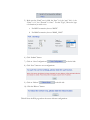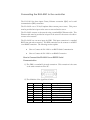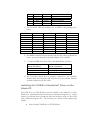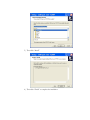
1
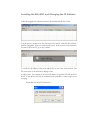
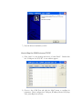
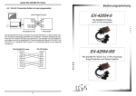
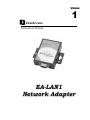
Volume
1
EverAccess
Instruction Manual
EA-LAN1
Network Adapter
EVERFOCUS ELECTRONICS CORPORATION
EA-LAN1
Instruction Guide
© 2004 Everfocus Electronics Corp
2445 Huntington Drive
Phone 626.844.8888 • Fax 626.844.8838
All rights reserved. No part of the contents of this manual may be reproduced or transmitted in any
form or by any means without written permission of the Everfocus Electronics Corporation.
Preface
Read This First
It is extremely important that you read this guide to get started with your EverAccess
product.
Unpacking
Please be careful when you unpack the box due to the electronics devices contained
inside. Check to make sure that you the original box contains the following items:
•
Communication Server with 1 serial port
•
1 power adapter: input voltage of 90~264VAC, output voltage 5V, current 2A
•
1 Installation CD and 1 User’s Manual
If an item appears to have been damaged in shipment, replace it properly in its carton
and notify the shipper. If any items are missing, notify your Everfocus Electronics
Corporation Sales Representative or Customer Service. The shipping carton is the
safest container in which the unit may be transported. Save it for possible future use.
Safety Warning
•
To prevent fire or shock hazard, do not expose this equipment to the
environment of high humidity and dust. So do not use it in an unprotected
outdoor installation or any area classified as a wet area
•
Installation environment: The temperature should be kept between 14°F
~140°F
•
For safety sake, do not disseminate the unit or put it on an unstable base
•
Ventilation: openings in the enclosure are provided for ventilation and to
ensure reliable operation of the unit and to protect it from overheating. These
openings must not be blocked or covered. This unit should not be placed in a
built-in installation unless proper ventilation is provided.
•
Cleanse: unplug the unit from the outlet before cleansing. Do not use liquid
cleaners or aerosol cleaners. Use a damp cloth to clean it.
•
Overload. Do not overload outlets and extension cords as this may result in a
fire or electric shock.
•
Power-cord protection: Power-supply cords should be routed so that they are
not likely to be walked on or pinched by items placed upon or against them,
paying particular attention to cords at plugs, convenience receptacles, and the
point where they exit from the appliance.
•
Object and liquid Entry: Never push objects of any kind into this unit
through openings as they may touch dangerous voltage points or short-out
parts that could result in a fire or electric shock. Never spill liquid of any kind
on the unit.
•
Service: Do not attempt to service this unit by yourself as opening or
removing covers may expose you to dangerous voltage of other hazards.
Refer all servicing to qualified service personnel.
Contents
CHAPTER 1
Product Overview...................................................................................................................1
Features and Specifications .................................................................................................1
CHAPTER 2
Installation Overview.............................................................................................................3
Locating the EA-LAN1 and Changing the IP Address .................................................4
Configuring the EA-LAN1 ...............................................................................................5
Connecting the EA-LAN1 to the controller...................................................................8
How to Connect the EA-LAN1 to an RS232 Serial Communication...................8
How to Connect the EA-LAN1 to an RS485 Connection .....................................9
Installing the “COM Port Simulation” Driver on the Admin PC................................ 10
How to Install COM Port over TCP/IP Driver...................................................... 11
How to Map the COM Ports over TCP/IP ............................................................ 13
Note ...................................................................................................................................... 15
Chapter
1
Product Overview
The EverAccess EA-LAN1 Network Adapter is a serial to TCP/IP adapter that
enables users to manage the EverAccess Flex Series controllers securely and
conveniently over a TCP/IP network. The EA-LAN1 should be installed in an
enclosure with the controller, and one EA-LAN1 is needed for each controller to be
accessed over the network. The EA-LAN1 can also be used to network other
manufacturers’ controllers (check with EverFocus for compatible products) or any
other device with a serial port.
Features and Specifications
Hardware
•
32-bit 100 MHz CPU
•
2M memory
•
10M/100M self-adapting net port
•
The speed of serial port can reach up to 230.4K
Software
•
Terminal mode can supports multi-screen switch
•
Supports PPP protocol and corresponding functions of dial in & dial out
•
Supports remote serial port or parallel port printing (RLP)
•
Provides programming interface
•
Provides TCP/UDP socket working mode, including server and client
•
Each serial port supports 6 sessions
•
Provides the settings for the network package
•
Supports SNMP agent
•
Port and network protocol TCP/IP, UDP, ICMP
•
Application protocol: Telnet, Rlogin, LPD and DNS
•
Security protocol: RADIUS PPP dial back, PAP and CHAP
1
E V E R F O C U S
E L E C T R O N I C S
C O R P O R A T I O N
•
Set the rights of different levels according to the user, IP address and MAC
address
•
Provides real COM drive under WINDOWS NT/2000/XP
•
Provides Static Route settings
•
Provides setup interface of menu in Chinese and English and WEB setup
interface
•
Supports state monitoring
•
Convenient online update through flash ROM
2
Chapter
2
Installation Overview
The EA-LAN1 provides convenient remote management of the controller over the
internet or local area network. There are a few steps to follow to properly install the
EA-LAN1 and ensure proper connection. An overview of these steps is given below,
and the rest of this guide is devoted to a detailed description of the process. To
perform these steps, you will need to have the controller and readers installed, and
will need a computer at the location of the install (we’ll call this the “Installation PC”).
This computer can be the administration PC that will be used to manage the system,
but it does not have to be. A laptop or other PC can be used for step 1-6, and the
administration PC (we’ll call it the “Admin PC”) must be used in step 7.
Step 1: Install the EA-LAN1 software on the Installation PC using the CD included
with the EA-LAN1. Make sure that the installation PC is connected to the network
that will be used to manage the controller.
Step 2: Connect the EA-LAN1 to the local area network using a LAN cable, and
power up the EA-LAN1.
Step 3: Using the software that you installed in Step 1 on the Installation PC, locate
the EA-LAN1 on the local area network and change the IP address on the EALAN1.
Step 4: Configure the EA-LAN1 as described in the detailed description later in this
guide.
Step 5: Connect the EA-LAN1 to the controller. (Note: Perform this step only after
successfully completing steps 1-5)
Step 6: Install the “COM Port Simulator” driver on the Admin PC using the CD
included with the EA-LAN1, and map the COM Port to be used.
Step 7: Confirm that the controller is now available on the network. At the Admin
PC, open the EverAccess Flex Software and connect to the controller using the
COM Port mapped in Step 7.
Locating the EA-LAN1 and Changing the IP Address
1) Run the upgrade.exe software from the CD included with the EA-LAN1.
2) If the server is connected to the same network as the PC used with this software,
click the “Magnifier” button to search for the server. If the server is not connected to
the same LAN as the PC, go to step 3 below.
3) Usually, the IP address of the server and the PC are not in the same network. The
PC can connect to the network by adding a route.
4) Add a route. For example, if the server IP address is 192.168.0.233 and the IP of
the PC is 24.0.46.144, then use the command mode (click Run-> start) to add a route
by typing:
Route add 192.168.0.233 24.0.46.144
5) Now, set a temporary IP address for the server in the same network by clicking on
“Tools” and selecting “Temporary change IP address”.
6) Type in the IP address of the PC and press “OK”
Click “OK”
7) Now you can enter the setting for the server using Web browser under windows.
Please refer to the section “ Configuring the EA-LAN1”.
Configuring the EA-LAN1
You can use the Web browser to configure the server. Place the server’s IP address
in the browser and press enter. The server configuration window appears.
1) Click on “Mode” of the menu on the left side and choose the corresponding
Port (Port1)
2) Choose the Port mode setting for “TCP realport” option from the “Mode”
menu.
3) Click on “Submit” button.
4) Click on “Async” from the menu on the left side and choose the
corresponding Port (Port 1).
5) Make sure the “Baud” rate is 9600, the “data” is 8, the “stop” bit is 1, the
“Parity” is “n”, the “Flowctrl” is “none”. For the “Type”, choose the type
of connection you wish to use.
a. For RS232 connection, choose “RS232”
b. For RS485 connection, choose “RS485_HALF”
6) Click “Submit” button.
7) Click on “Save Configurations”
on the left side.
8) Click “Save” button to save configurations.
9) Click on “Reboot”
on the left side.
10) Click the “Reboot” button.
This will close the Web page reboot the server with new configurations.
Connecting the EA-LAN1 to the controller
The EA-LAN1 has three inputs: Power, Ethernet connection (RJ45) and a serial
communication (DB9) connection.
The EA-LAN1 uses a 5Volts/1Amphere direct current power source. This power
must be provided at its input on the server to turn and run the server.
The EA-LAN1 connects to the network using a standard RJ45 Ethernet cable. This
Ethernet cable must be provided at its input on the server for the server to be able to
connect to the network.
The EA-LAN1 has one more input, the DB9. This input connection is a standard
RS232 nine pin male connection. The DB9 connection can be connect to an RS232
or an RS485 connection. The following sections explain:
•
How to Connect the EA-LAN1 to an RS232 Serial Communication
•
How to Connect the EA-LAN1 to an RS485 Connection
How to Connect the EA-LAN1 to an RS232 Serial
Communication
11) The DB9 is a standard 9 pin male connection. This connection is the same
as the serial connection on the PC.
12) The definition of the signal lines is below.
1
2
3
4
5
6
7
8
9
Name
DCD
RxD
TxD
DTR
GND
DSR
RTS
CTS
RI
Direction
Input
Input
Output
Output
---Input
Output
Input
Input
Specification
Data carrier wave test
Data receiving
Data sending
Data terminal ready
Signal ground wire
Data equipment ready
Request for sending
Delete sending
Ring test
13) The EA-LAN1 pin definition for an RS232 corresponding pin is below.
DB9 PIN #
1
2
3
4
5
6
7
8
9
RS232
DCD
RXD
TXD
DTR
GND
DSR
RTS
CTS
N/A
RS485-Half
N/A
DATADATA+
N/A
GND
N/A
N/A
N/A
N/A
RS485-Full
N/A
TXDTXD+
RXD+
GND
RXDN/A
N/A
N/A
RS422
RTSTXDTXD+
RXD+
GND
RXDRTS+
CTS+
CTS-
14) The RS232 connection must be matched with the device being used with the
server. In our case the device is the Main Module of the controller.
15) Connect the DB9 of the server to the Main Module as follows:
DB9
(Pin # - Pin Name)
2 – RX
3 – TX
5 – GND
RS232 on Main Module
(Pin # - Pin Name)
14 – TX
13 – RX
12 – GND
16) That’s all. Make sure the connection is correct, the power and the Ethernet
are both plugged in.
How to Connect the EA-LAN1 to an RS485 Connection
1) The DB9 is a standard 9 pin male connection. This connection is the same
as the serial connection on the PC.
2) The definition of the signal lines is below.
1
2
3
Name
DCD
RxD
TxD
Direction
Input
Input
Output
Specification
Data carrier wave test
Data receiving
Data sending
4
5
6
7
8
9
DTR
GND
DSR
RTS
CTS
RI
Output
---Input
Output
Input
Input
Data terminal ready
Signal ground wire
Data equipment ready
Request for sending
Delete sending
Ring test
3) The EA-LAN1 DB9 pin definition for an RS485 corresponding pin is
below.
DB9 PIN #
1
2
3
4
5
6
7
8
9
RS232
DCD
RXD
TXD
DTR
GND
DSR
RTS
CTS
N/A
RS485-Half
N/A
DATADATA+
N/A
GND
N/A
N/A
N/A
N/A
RS485-Full
N/A
TXDTXD+
RXD+
GND
RXDN/A
N/A
N/A
RS422
RTSTXDTXD+
RXD+
GND
RXDRTS+
CTS+
CTS-
4) The RS485 connection must be matched with the device being used with the
server. In our case the device is the Main Module of the controller.
5)
Connect the DB9 of the EA-LAN1 to the Main Module as follows:
DB9
(Pin # - Pin Name)
2 – RX
3 – TX
5 – GND
RS485 on Main Module
(Pin # - Pin Name)
11 – RS485_B
10 – RS485_A
12 – GND
6) The EA-LAN1 should now be properly connected to the controller.
Double check the connection, and verify that the power and the Ethernet
are both connected to the EA-LAN1.
Installing the “COM Port Simulation” Driver on the
Admin PC
The COM Port over TCP/IP driver must be installed on the admin PC to allow
Windows to communicate with the EverAccess controller through the net. In this
chapter you will learn how to install this driver and be able to map it to the COM
ports available through the PC. The following two sections in this chapter help
explain:
•
How to Install COM Port over TCP/IP Driver
•
How to Map the COM Ports over TCP/IP
How to Install COM Port over TCP/IP Driver
1) Run 60x_2k_4.1 .1 in CD-ROM.
2) Click “Yes” to begin the installation of the terminal server.
3) Click “Next”
4) To keep the installation directory the same, click “Next”, other wise choose
a different directory to install the driver.
5) Then click “Install”
6) Then click “Finish” to complete the installation.
7) Now the driver is installed in your PC.
How to Map the COM Ports over TCP/IP
1) Click “Start” on your desktop and choose “Control Panel”. Double click
the “COM port over TCP/IP”. A new window appears.
2) Choose a free COM Port and click the “Map” button to configure its
parameters. Please configure the COM port, IP address, Device Port, Keep
Alive, status Report at one time.
a) COM port: is the COM port resource that WINDOWS uses.
b) Device IP address: is the IP address of server.
c) Device Port: is the number of serial ports to be mapped to the
server.
d) Keeplive: is the TTL (time-to-live) of serial port; it is normally set as
300 second. Usually 300 for TCP/IP.
e) Status Report: is the status report.
3) Click the “OK” button.
4) Click “Save”
button and the settings of the COM port
become completely effective.
Please Note: Under Windows, the COM port can be mapped while the
server offline. So there will be no problem if you install and set the drive
first and then connect the terminal server to the network.
Notes:
Head Office
12F, No.79 Sec.1 Shin-Tai Wu Road,
Hsi-Chi, Taipei, Taiwan
Tel
:+ 886-2-26982334
Fax
:+ 886-2-26982380
European Office
Albert-Einstein-Strasse 1,
D-46446 Emmerich, Germany
Tel
: + 49-2822-9394-0
Fax
: + 49-2822-939495
USA Office
1801 Highland Ave.Duarte,CA
Building.
91010 ,U.S.A
Tel
:+ 1-626-844-8888
Fax
:+ 1-626-844-8838
Beijing office:
Room 609,Technology Trade
Shangdi Information Industry Base,
Haidian District,Beijing China
Tel
:+ 86-10-62971096
Fax
:+ 86-10-62971423
Japan Office
1809 WBG Marive East 18F,
2-6 Nakase, Mihama-ku,
Chiba city 261-7118, Japan
Tel
: + 81-43-212-8188
Fax
: + 81-43-297-0081
EverAccess