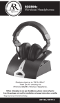
1
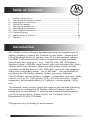
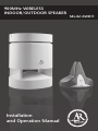
900MHz WIRELESS
INDOOR/OUTDOOR SPEAKER
Installation
and Operation Manual
Model AW811
Table of Contents
I. Location of functions………..…………………………………………….… 2
II. Connecting the speaker system............................................................ 3
III. Adjusting the transmitter...................................................................... 5
IV. Tuning the speaker……………………………………………………………6
V. Turning the speaker off……………………………………………………… 7
VI. Recharging the batteries……………………………………………………. 7
VII. More helpful information ..................................................................... 7
VIII.Troubleshooting .................................................................................. 9
IX. Specifications & Features ..................................................................... 10
X. Warranty ……………………………………………………………………... 11
Introduction
AR’s Wireless Indoor/Outdoor Speaker eliminates the hardest part of
adding speakers to almost any location in your home – running and
hiding hundreds of feet of speaker wire. As a water-resistant speaker,
the AW811 will withstand the effects of exposure to light moisture
(drizzle rain, dew from grass, etc.). Like FM radio, the AR Wireless
Speaker System’s 900MHz signal travels with ease through walls, floors,
ceilings and other obstacles, delivering high-quality sound virtually
anywhere inside the house or out. With drift- and static-free reception
along with outstanding range – up to 300 feet* – the possibilities for
enjoying your AR Wireless Speaker System are nearly unlimited.
The AR Wireless Indoor/Outdoor Speaker is compatible with most audio
sources, such as TVs, DVD players, VCRs, A/V receivers/amps, stereos,
computers, and portable devices (CD players, cassette players, MP3s,
etc.).
This manual covers various connection options and detailed operating
instructions for making the AR Wireless Indoor/Outdoor Speaker a
valued part of your lifestyle. If, after having reviewed the instructions,
you have any questions, please contact our Customer Service
Department at 1-800-732-6866.
*Range may vary according to environment.
1
I. Location of Functions
Speaker Side View:
Speaker Front View:
A
D
B
C
A.Power/tuning indicator light
B. Power/tuning/volume control
C. Speaker power input jack
D. Left/mono/right switch
Speaker Top View:
Speaker Bottom View:
E
G
F
E. Carrying handle
F. Non-skid table surface
G. Battery compartment cover
Transmitter Front View:
Transmitter Back View:
J
H
H.Power indicator light
K
I
I. Transmitter power input jack
J. Audio input cable
K.Channel select switch
Accessories:
dio Output
O. 1/4” headphone
IMPORTANT: These power units are
intended to be correctly inserted in a
vertical or floor mount position.
adapter
L. Transmitter AC
N.“Y” adapter cable
M. Speaker AC power
power adapter 12V DC
adapter - 18V DC
2
Audio Output
II. Connecting the Speaker System
Audio Output
I. Powering the Transmitter
Connect the small, round plug from the transmitter AC power adapter (L) to
the transmitter power input jack (I) and plug the other end of the transmitter
Sortie audio
AC power adapter (L) into any standard 120V AC wall outlet.
Audio Output
Note: Be sure to use the AC power
Transmitter
adapter rated 12V DC 100
mA.
Sortie audio
Note: There is no transmitter ON/OFF
switch. The transmitter is designed to be
left plugged in and powered at all times.
If you will not be using the AW811 for
an extended period of time, you may
wish to unplug the transmitter AC power
adapter.
AC Power
Adapter (L)
I
120V AC
wall
outlet
II. Connecting to an Audio Source:
i. Connecting to an A/V Receiver: Audio Output
“Y” adapter cable (N)
Audio Output
Audio Output
Battery
Battery
Battery
Battery
Battery
Battery
Battery
TV
Transmitter
AW871
Audio Output
Audio Output
Battery
Battery
Battery
Battery
3
1/4” headphone
adapter (O)
Battery
Audio Input Cable (J)
Battery
Stereo
Battery
Sortie audio
Battery
Transmitter
Battery
Sortie audio
Battery
iii. Connecting to a Stereo or a Computer:
Battery
“Y” adapter cable (N)
Audio Input Cable (J)
Battery
Battery
ii. Connecting to a TV:
Battery
Audio Input Cable (J)
Battery
AW811
Battery
A/V Receiver
1. Connect the included “Y” adapter cable (N) to the 3.5mm mini plug cable coming out of the transmitter.
2. Connect the RCA-type left (white) and right (red) audio plugs on the ”Y” adapter cable to the corresponding left and right audio outputs of your A/V receiver, amp or other audio source.
1. Connect the included “Y” adapter cable (N) to the 3.5mm mini plug Sortie audio
cable coming out AW811
of the
transmitter.
2. Connect the RCA-type
left (white) AW811
and right (red) audio plugs on the “Y” adapter cable to the corresponding left and right audio outputs on the TV.
Battery
Audio Output
Transmitter
AW871
Plug the cable coming out of the
AW871
transmitter into
the headphone
output of your stereo or the audio
output jack on your computer.
Use the included 1/4” headphone
adapter (O) to convert the 3.5mm
plug to a 1/4” plug as needed.
Warning: This product is designed to work with line level outputs or
headphone outputs only. DO NOT connect it directly to speaker outputs as it
will permanently damage the transmitter.
Sortie audio
III. Powering the Speaker
There are two options to power your wireless speaker:
i. AC Power Adapter:
1.
2.
Speaker
AC Power
adapter (M)
Turn the speaker volume down by rotating the power/volume/scan control (B) on the side of the speaker all the way to the left.
Insert the small, round plug from the
speaker AC power adapter (M) into
the speaker power input jack (C).
Plug the other end of the speaker AC power adapter into any standard 120V AC wall outlet. Note: Be sure to use the speaker AC power adapter rated 18V DC 700 mA.
3.
Speaker power
input jack (C)
Warning: This product is water resistant, not waterproof. To avoid electrical
shock, it should be used with caution near water sources if powered with the
AC adapter. Never submerge in water.
120 V AC
Wall
Outlet
ii. C-cell Batteries:
Battery
compartment
cover (G)
1. Turn the speaker volume down by rotating the power/volume/scan control (B) on the side of the speaker all the way to the left.
2.
3.
Remove the battery compartment cover (G) on the bottom of the speaker.
Insert eight (8) C-cell batteries (not
included) into the speaker following the polarity (“+” and
“–”) as diagrammed inside the
battery compartment.
Note: Place the rubber cap in the speaker power input jack (C) when using batteries.
Important:
Battery
Battery
Battery
Battery
If you are using NiMH or NiCd batteries, the batteries will charge when the
headphones are powered with the AC power adapter. Do not power the headphones with the AC power adapter if you installed alkaline or other non-reAW811
chargeable batteries—this could cause the batteries to leak. Do not mix batteries with different chemistry types (for example, a zinc battery with an alkaline
battery). Do not mix new and used batteries. Do not leave batteries installed in
the product when not in use for long periods.
4
Batter
Batter
III. Adjusting the Transmitter
J
I
K
H
H.Power indicator light
I. Transmitter power input jack
J. Audio input cable
K.Channel select switch
1. Turn ON your audio source (i.e., A/V receiver, TV, stereo, etc.) and play music at a normal listening volume.
2.
5
Set the channel select switch (K) on the back of the transmitter to 1, 2 or 3. The transmitter provides three different broadcasting frequencies. In the event that you experience poor reception or interference, try choosing a different frequency by moving the channel select switch to another position.
IV. Tuning the Speaker
Speaker Front View:
Speaker Side View:
D
A
A.Power/tuning indicator light
B
C
B. Power/tuning/volume control
C. Speaker power input jack
D. Left/mono/right switch
1. Press the Power/tuning/volume (B) up to turn the speaker ON. The power/tuning indicator light (A) will illuminate red until the speaker is tuned to the transmitter and then the light will illuminate green, indicating that the speaker is tuned properly. You should hear sound coming from the speaker now. Note: If the speaker is not tuned or if the transmitter is not connected properly, the power/tuning indicator light will continue to illuminate red. If this occurs, please see the troubleshooting section of this manual.
2. Adjust the volume on the speaker as desired.
3.
Mono/stereo operation set up:
a) Monaural operation: The monaural mode (MONO) is recommended when using a single speaker or if using more than one speaker in different locations.
For monaural operation, set the left/mono/right switch (D) to “MONO” on each speaker.
b) Stereo operation: You will need an additional AW811 speaker in order to utilize the stereo option.
For stereo operation, set the left/mono/right switch (D) to “L” on the speaker located to the left from the listener, and set the other speaker to the “R” position.
Note: Interference in the form of static and/or distortion can sometimes be heard. If this occurs, confirm the transmitter/speaker adjustments and indicators. If the problem persists, refer to the Troubleshooting section of this manual.
6
V. Turning the Speaker Off
1. Press and hold the Power/tuning/volume (B) up to turn the speaker OFF. You will need to hold the control for about 1.5 seconds for the speaker to turn off.
2. Confirm that the speaker is off by verifying that the power/tuning indicator light (A) is no longer illuminated.
VI. Recharging the Batteries
The speaker will automatically charge the rechargeable batteries (NiMH or NiCd)
only when the batteries are installed and the speaker is plugged in with the AC
power adapter.
Warning: DO NOT attempt to charge any other batteries except those specified above.
VII. More Helpful Information
i. About Fixed-Level Audio Outputs:
A fixed-level, or line-level audio output is considered ideal since it provides an
audio signal unchanged by adjustments to the audio source volume control.
Hint: Fixed-level audio outputs from stereo receivers/amps will typically be designated as Tape, Tape 1, and Tape 2 outputs, or VCR audio output connections These outputs are frequently marked on A/V equipment as ‘TAPE OUTPUT,’ ‘TAPE OUT,’ ‘TAPE REC, or ‘TAPE RECORD or REC OUT.’
Please note: Jacks labeled PHONO, CD, LD, DVD or tape or VCR playback (PB) are INPUTS and will not work with the transmitter.
Fixed-level outputs from TVs are usually marked as ‘Constant,’ ‘Fixed,’ or
‘Select.’ If they are not marked as such, they are probably variable outputs (see
“About Variable-Level Audio Outputs” on the next page). Outputs from VCRs
are almost always fixed.
7
Hint: When connecting to the audio outputs of a VCR, remember that the VCR must be playing a tape or showing a TV channel for sound to be produced.
Hint: If your VCR (or other audio source with RCA jacks) only has a single audio output, you will need another RCA “Y” cable. It differs from the “Y” Cable Adapter included with this speaker. It will have a single male RCA plug and 2 female RCA jacks. Connect the dual RCA plugs from the included “Y” cable adapter to the 2 female RCA jacks on the second “Y” cable, and then connect the single male RCA plug of the second “Y” cable to the single audio output of the VCR.
ii. About Variable-Level Audio Outputs:
A variable-level output, such as a headphone jack or certain RCA-type outputs,
provides an audio signal that changes with the volume level set on the audio
source. As the volume of the audio source is adjusted up and down, so is
the audio signal strength sent to the transmitter. This can affect the quality
of sound generated by the speaker, and may require an adjustment of the
volume level of the audio source to produce a signal strong enough for the
transmitter.
Hint: On most bookshelf-type or compact stereo systems, inserting a headphone plug into the headphone jack results in automatic cutoff of the regular, or hard-wired speakers.
Hint: Most TVs, regardless of age or price, have variable outputs. If you are unsure which of your TV audio outputs is fixed, refer to the TV instruction manual. Some TVs have outputs that can switch between variable and fixed. When given a choice, fixed is always recommended.
8
VIII. Troubleshooting
The following troubleshooting guide takes you through some of the more
common problems associated with the installation and/or operation of a wireless
system. If the problem persists, please call 1-800-732-6866 and a knowledgeable
customer service representative will assist you.
Issue:
Cause and solution:
No
sound
• Check that the transmitter AC power adapter is fully inserted into the wall outlet and the power cord from the AC adapter is firmly connected to the transmitter power input jack.
• Confirm that the speaker is turned ON and tuned to the transmitter – the power/tuning indicator light (A) on the front of the speaker should illuminate green.
• Confirm that the speaker AC power adapter is fully inserted into the wall outlet and the power cord on the AC power adapter is firmly connected to the speaker power input jack.
or
• Check that the C-cell batteries are fresh and inserted with correct polarity
(+, –).
• Check that the audio source component (stereo, TV, etc.) is turned on and
transmitting sound as it normally should.
• Check that the speaker volume is turned up.
• If you are using a Tape 2 Monitor output from your receiver/amp as the audio output, check that you have pressed the Tape Monitor/Tape 2 button on the front of the receiver. This will turn on the Tape 2 outputs, which may not have been active.
Issue:
Cause and solution:
No
sound/
distortion/
static
• When using battery power, make sure the batteries are fresh and replace if necessary.
• Check that the speaker power/tuning indicator light (A) is illuminated green.
• Change the position of the channel select switch (1, 2 or 3) to change the operating frequency. The speaker will detect the loss of signal and retune automatically. However, you can also press the Power/tuning/volume up once to make the speaker retune.
• Change the location of the transmitter. Place it as high and away from obstructions as possible. Avoid placing the transmitter directly on top of or behind a TV.
• Move the transmitter and speaker closer together. Sending the signal through certain materials, such as glass, tile, and metal, can decrease the effective transmitting distance of the system.
9
IX. Specifications & Features
Transmitter:
Omnidirectional
Effective transmitting range: up to 300 feet*
3 selectable broadcast frequencies (between 912.5 and 914.5 MHz)
Stereo audio input with 3.5mm stereo mini plug (1/4” headphone adapter and
“Y” cable included)
UL-listed AC power adapter
Speaker:
Push-button, auto-lock tuning
20 Watts per channel RMS
Digital amplifier
Two-way acoustic suspension design
1”dome tweeter; 5” woofer
Integrated power/tuning/volume control
Left/mono/right switch
Frequency response: 40Hz - 15kHz
Signal-to-noise ratio > 60dB
*Maximum range; results may vary according to environment.
This device complies with part 15 of the FCC rules. Operation is subject to the
following two conditions: 1) This device may not cause harmful interference
and 2)This device must accept any interference received, including interference
that may cause undesired operation.
Changes or modifications not expressly approved by the party responsible for
compliance could void the users authority to operate the equipment.
Features and specifications subject to change without notice.
10
X. Warranty
12 MONTH LIMITED WARRANTY
Audiovox Electronics Corporation (the “Company”) warrants to the original retail
purchaser of this product that should this product or any part thereof, under normal use
and conditions, be proven defective in material or workmanship within 12 months from
the date of original purchase, such defect(s) will be repaired or replaced (at the Company’s
option) without charge for parts and repair labor. To obtain repair or replacement within
the terms of this Warranty, the product along with any accessories included in the original
packaging is to be delivered with proof of warranty coverage (e.g. dated bill of sale),
specification of defect(s), transportation prepaid, to the Company at the address shown
below. Do not return this product to the Retailer.
This Warranty is not transferable and does not cover product purchased, serviced or used
outside the United States or Canada. The warranty does not extend to the elimination
of externally generated static or noise, to costs incurred for the installation, removal or
reinstallation of the product. The warranty does not apply to any product or part thereof
which, in the opinion of the company, has suffered or been damaged through alteration,
improper installation, mishandling, misuse, neglect, accident or exposure to moisture.
This warranty does not apply to damage caused by an AC adapter not provided with the
product, or by leaving non-rechargeable batteries in the product while plugged into an
AC outlet.
THE EXTENT OF THE COMPANY’S LIABILITY UNDER THIS WARRANTY IS LIMITED TO
THE REPAIR OR REPLACEMENT PROVIDED ABOVE AND, IN NO EVENT, SHALL THE
COMPANY’S LIABILITY EXCEED THE PURCHASE PRICE PAID BY PURCHASER FOR THE
PRODUCT. This Warranty is in lieu of all other express warranties or liabilities. ANY IMPLIED
WARRANTIES, INCLUDING ANY IMPLIED WARRANTY OF MERCHANTABILITY OR FITNESS
FOR A PARTICULAR PURPOSE, SHALL BE LIMITED TO DURATION OF THIS WARRANTY.
ANY ACTION FOR BREACH OF ANY WARRANTY HEREUNDER, INCLUDING ANY IMPLIED
WARRANTY, MUST BE BROUGHT WITHIN A PERIOD OF 24 MONTHS FROM THE DATE
OF ORIGINAL PURCHASE. IN NO CASE SHALL THE COMPANY BE LIABLE FOR ANY
CONSEQUENTIAL OR INCIDENTAL DAMAGES WHATSOEVER. No person or representative
is authorized to assume for the Company any liability other than expressed herein in
connection with the sale of this product. Some states/provinces do not allow limitations
on how long an implied warranty lasts or the exclusion or limitation of incidental or
consequential damage so the above limitations or exclusions may not apply to you. This
Warranty gives you specific legal rights and you may also have other rights which vary
from state/province to state/province.
U.S.A.: Audiovox Electronics Corporation, 150 Marcus Blvd., Hauppauge, New York 11788
CANADA: Audiovox Return Center, c/o Genco, 6685 Kennedy Road, Unit 3, Door 16,
Mississauga, Ontario L5T 3A5
© 2007 Audiovox Accessories Corporation
111 Congressional Blvd., Suite 350
Carmel, IN 46032 USA
AD_39382
06/07
11
www.araccessories.com
MADE IN CHINA