1
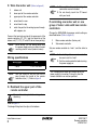
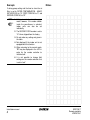
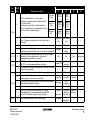
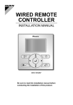
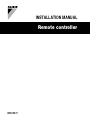
INSTALLATION MANUAL
Remote controller
BRC1D517
2
1
3
S
M
1
PCB
1
S
M
2
1
1
4
2
3
2
7
5
a
1
d
UNIT No.
5
4
b
GROUP
SETTING
6
1
P2 P1
1
e
c
4
6
3
P2 P1
1
7
6
2
5
2
7
8
3
4
6
5
8
2
1+2
2
2
BRC1D517
Remote controller
READ THIS MANUAL ATTENTIVELY
BEFORE STARTING UP THE UNIT. DO
NOT THROW IT AWAY. KEEP IT IN YOUR
FILES FOR FUTURE REFERENCE.
IMPROPER
INSTALLATION
OR
ATTACHMENT OF EQUIPMENT OR
ACCESSORIES COULD RESULT IN
ELECTRIC SHOCK, SHORT-CIRCUIT,
LEAKS, FIRE OR OTHER DAMAGE TO
THE EQUIPMENT. BE SURE ONLY TO
USE ACCESSORIES MADE BY DAIKIN
WHICH ARE SPECIFICALLY DESIGNED
FOR THE USE WITH THE EQUIPMENT
AND HAVE THEM INSTALLED BY A
PROFESSIONAL.
IF UNSURE OF INSTALLATION PROCEDURES OR USE, ALWAYS CONTACT
YOUR DEALER FOR ADVICE AND
INFORMATION.
The kit includes the following parts:
Remote controller
Wood screws
Installation manual
Wall plugs
Machine screws
1. Remove the upper part of remote
controller (Refer to figure 1)
Insert a minus screwdriver into the slots (1) in the
lower part of the remote controller (2 places), and
remove the upper part of the remote controller.
The PC board is mounted in the upper part
of the remote controller. Be careful not to
damage the board with the minus
screwdriver.
2. Fasten the remote controller
(Refer
to figure 2)
1
for exposed mounting, fasten with the two
included wood screws (Ø4x30) and plugs.
2
for flush-mounting, fasten with the two
included machine screws (M4x16).
For the field supplied switch box, use optional accessory
KJB111A or KJB211A.
NOTE
BRC1D517
Remote controller
4PW15195-1
Choose the flattest place possible for
mounting surface. Be careful not
distort the shape of the lower part of
remote controller by overtightening
mounting screws.
the
to
the
the
Installation manual
1
3. Wire the indoor unit
(Refer to figure 6)
1
indoor unit
2
lower part of the remote controller
3
upper part of the remote controller
4
wired from the rear
5
wired from the top
6
notch the part for the wiring to pass through
with nippers, etc.
Connect the terminals on top of the upper part of the
remote controller (P1, P2), and the terminals of the
indoor unit (P1, P2). (P1 and P2 do not have polarity.)
NOTE
When wiring, run the wiring away from
the power supply wiring in order to avoid
receiving electric noise (external noise).
NOTE
If controlling one indoor unit or one
group of indoor units with two remote
controllers
Change the MAIN/SUB changeover switch setting as
described below (Refer to figure 3).
1
Main remote controller (factory set)
2
Sub remote controller
Set one remote controller to “main”, and the other to
“sub”.
NOTE
Wiring specifications
Wiring type
Size
2 wire
0.75–1.25 mm2
NOTE
Peel the shield for the part that has to
pass through the inside of the remote
controller case ( l ). Refer to figure 5.
1. The switch box and wiring for
connection are not included.
2. Do not directly touch the PC board
with your hand.
1. If controlling with one remote controller,
be sure to set it to “main”.
2. Set the remote controller before turning
the power supply on.
“88” is displayed for about one minute when the
power supply is turned on. During this time the
remote controller can not be operated.
4. Reattach the upper part of the
remote controller
Be careful not to pinch the wiring when
attaching.
Refer to figure 4:
First begin fitting from the clips at the bottom.
Installation manual
2
BRC1D517
Remote controller
4PW15195-1
5. Permission level function
6. Field settings
■
If optional accessories are mounted on the indoor
unit, the indoor unit setting may have to be changed.
Refer to the instruction manual for each optional
accessory.
If required, you can limit the user action by
restricting the number of operable buttons. Refer
to the chapter "Field settings".
Level
All
2
•
•
•
•
•
•
3
■
Operable buttons
1
• on/off button
• temperature adjust button
• fan speed button
Keep the fan speed button
2
■
on/off button
schedule timer button
temperature adjust button
operation change/
button
fan speed button
air flow direction adjust button
For switching between level 1 permission and the
selected level in service, proceed as follows:
1
a
Unit NO
b
First Code NO
c
Second Code NO
d
Mode NO
e
Field set mode
Procedure
(Refer to figure 7)
1
When in the normal mode, press the “
“
button for a minimum of four seconds, and the
FIELD SET MODE is entered.
2
Select the desired MODE NO. with the “
button.
3
During group control, when setting by each
indoor unit (mode No. 20, 21, 22 and 23 have
been selected), push the “
” button and
select the INDOOR UNIT NO. to be set. (This
operation is unnecessary when setting by
group.)
4
Push the “
” upper button and select
FIRST CODE NO.
5
Push the “
” lower button and select the
SECOND CODE NO.
6
Push the “
” button once and the present
settings are SET.
7
Push the “
MODE.
pressed,
and press the 3 other indicated keys
simultaneously while keeping the fan speed
button
pressed.
Refer to figure 8.
If you want to limit the user action on the remote
controller to be defined as “sub”, start with only
connecting this controller to the unit. Make sure
that this controller is set to “main” (factory set)
first, change the permission level to the setting
you prefer and only then set the remote controller
to “sub”.
You can now proceed with connecting the remote
controller to be defined as “main”.
BRC1D517
Remote controller
4PW15195-1
Refer to figure 7.
”
” button to return to the NORMAL
Installation manual
3
Example
Notes
If during group setting and the time to clean the air
filter is set to FILTER CONTAMINATION - HEAVY,
SET MODE NO. to “10”, FIRST CODE NO. to “0”, and
SECOND CODE NO. to “02”.
NOTE
1. Setting is carried out in the group
mode, however, if the mode number
inside the parentheses is selected,
indoor units can also be set
individually.
2. The SECOND CODE number is set to
“01” when shipped from the factory.
3. Do not make any settings not given in
the table.
4. Not displayed if the indoor unit is not
equipped with that function.
5. When returning to the normal mode,
“88” may be displayed in the LCD in
order for the remote controller to
initialize itself.
6. It is not possible to change field
settings on the remote controller that
is set to “sub”.
Installation manual
4
BRC1D517
Remote controller
4PW15195-1
Description of setting
Filter Contamination - Heavy/Light
(Setting for spacing time of display time
to clean air filter)
(Setting for when filter contamination is
heavy, and spacing time of display time to
clean air filter is to be halved)
10(20)
11(21)
15(25)
02
Approx.
10.000
hrs.
Approx.
5.000
hrs.
Long life
filter
Approx.
2.500
hrs.
Approx.
1.250
hrs.
Standard
filter
1
Long-life filter type (setting of filter sign indication
time). (Change setting when ultra-long filter is
installed)
2
Thermostat sensor in remote controller
3
Spacing time of display time to clean air filter count
(setting for when the filter sign is not to be displayed)
0
Approx.
200 hrs.
03
04
—
—
—
—
Approx.
100 hrs.
Long-life
filter
Ultra-long life
filter
Use
Not use
—
—
Display
Do not
display
—
—
Setting number of connected Sky Air simultaneous
operation system indoor units (setting for
simultaneous operations system)
Pair
Twin
Triple
Double twin
1
ON/OFF input from outside (setting for when forced
ON/OFF is to be operated from outside).
Forced OFF
ON/OFF
operation
—
—
2
Thermostat differential changeover (setting for when
using remote sensor).
1°C
0.5°C
—
—
0
High air outlet velocity (for high ceiling applications).
≤2.7 m
1
Selection of air flow direction (setting for when a
blocking pad kit has been installed).
3
Selection of air flow function (setting for when using
a decoration panel for outlet).
4
Air flow direction range setting.
Normal
6
Setting the external static pressure (setting
according to the connected duct resistance)
(for FHYK, follow the high ceiling setting)
(Normal)
Drain pump operation with humidifying.
Equipped
12(22)
13(23)
01
Ultra long
life filter
Light
0
SECOND CODE NO. Note 2
Heavy
Mode FIRST
No. CODE
Note 1 NO.
3
BRC1D517
Remote controller
4PW15195-1
>2.7≤3.0 m >3.0≤3.5 m
—
4-way flow
3-way flow
2-way flow
—
Equipped
Not
equipped
—
—
Upper
Normal
Lower
—
High static Low static
pressure
pressure
(High ceiling)
—
Not
equipped
—
—
—
Installation manual
5
Mode FIRST
No. CODE
Note 1 NO.
1b
SECOND CODE NO. Note 2
Description of setting
0
Permission level setting
1
Leave home function
2
Thermostat sensor in remote controller (for limit
operation and leave home function only)
01
02
03
Level 2
Level 3
—
04
—
Not permitted
Permitted
—
—
Use
Not use
—
—
Notes
Installation manual
6
BRC1D517
Remote controller
4PW15195-1
NOTES
Zandvoordestraat 300, B-8400 Oostende, Belgium
4PWEN15195-1