1
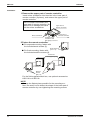
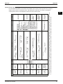
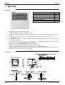
BRC1C62
ED39-634
1. BRC1C62
BRC1C62
Operation Functions with HRV
BRC1C62
ON / OFF Operation with Air Conditioner
"
Independent operation in intermediate season
"
Ventilation mode change over (Auto / HRV / Normal)
"
Air flow change over (Auto / High / Low)
"
Setting of precooling / preheating
#
Setting of fresh-up operation
#
Filter sign display
"
#: Initial Setting Only (Field setting by well known service person)
! Easier to read because LCD screen is larger.
! Digital display lets you set temperature in 1°C units.
! Lets you individually program by timer the respective times for operation start and stop within a maximum of 72
hours.
! Equipped with a thermostat sensor in the remote controller that makes possible more comfortable room
temperature control.
! Enables you to select cool/heat/fan operation mode with the indoor remote controller of your choice without using
the cool/heat selector.
! Constantly monitors malfunctions in the system for 80 items, and is equipped with a "self-diagnosis function" that
lets you know by message immediately when a malfunction occurs.
! Lets you carry out various field settings by remote controller.
! Enables you to select the ventilation mode and the volume of the HRV.
! The rubber switch and the oil-resisting resin casing have been adopted for durability.
*When the auto-swing function is not available, the message, THIS FUNCTION IS NOT AVAILABLE is displayed
when the wired direction adjustment button is pressed.
Dimensions
3D028952
50
Wired Remote Controller
ED39-634
BRC1C62
3
C: 3P171361-1
1. On/off button
Press the button and the system will start. Press the
button again and the system will stop.
2. Operation lamp (red)
The lamp lights up during operation.
3. Display “
” (changeover under control)
It is impossible to changeover heat/cool with the remote
controller which display this icon.
4. Display “
” (air flow flap)
5. Display “
” (ventilation/air cleaning)
This display shows that the ventilation unit are in
operation. (these are optional accessories)
6. Display “
C ” (set temperature)
This display shows the temperature you have set.
7. Display “
”“
”“
”“
”“
” (operation
mode)
This display shows the current operation mode.
8. Display “
” (programmed time)
This display shows the programmed time of the system
start or stop.
TEST ” (inspection/test operation)
9. Display “
When the inspection/test operation button is pressed,
the display shows the mode in which the system
actually is.
10. Display “
” (under centralized control)
When this display shows, the system is under
centralized control. (This is not a standard
specification.)
11. Display “
” (fan speed)
This display shows the fan speed you have selected.
12. Display “
” (time to clean air filter)
13. Display “
” (defrost/hot start)
14. Timer mode start/stop button
15. Timer on/off button
16. Inspection/test operation button
This button is only used by qualified service persons for
maintenance purposes.
17. Programming time button
Use this button for setting the programming start and/or
stop time.
18. Temperature setting button
Use this button for setting the desired temperature.
19. Filter sign reset button
Refer to the operation manual of indoor unit.
20. Fan speed control button
Press this button to select the fan speed of your
preference.
21. Operation mode selector button
Press this button to select the operation mode of your
preference.
22. Air flow direction adjust button
23. Thermistor
It sense the room temperature around the remote
controller.
24. These button are used when the ventilation unit are
installed (These are optional accessories)
Refer to the operation manual of the ventilation unit.
NOTE
•
•
•
In contradistinction to actual operating situations, the
display on figure 1 shows all possible indications.
Above figure shows the remote controller which is
opened the cover.
If that particular function is not available, pressing the
button may display the words “NOT AVAILABLE” for a
few seconds.
When running multiple units simultaneously the “NOT
AVAILABLE” message will only be appear if none of the
indoor units is equipped with the function. If even one
unit is equipped with the function, the display will not
appear.
C:3P171361-1
Wired Remote Controller
51
BRC1C62
ED39-634
Installation
1.Remove the upper part of remote controller.
Insert minus screwdriver into the slots in the lower part of
remote controller (2 places), and remove the upper part of
remote controller.
The PC board is mounted in the
upper part of remote controller. Be
careful not to damage the board
with the minus screwdriver.
Upper Part of
Remote Controller
Lower Part of
Remote Controller
Minus screwdriver
Insert the minus
screwdriver and
twist lightly to remove.
2.Fasten the remote controller.
For exposed mounting, fasten with
the included wood screws (2).
! For flush-mounting, fasten with
Wood Screws
(φ3.5 x 16)
the included machine screws (2).
Switch Box
(Field supplied parts)
Machine
Screws
(M4 x 16)
For the field supplied switch box, use optional accessories
KJB111A or KJB211A.
NOTE
Choose the flattest place possible for the mounting surface. Be careful not to distort the shape of the lower part of
remote controller by over-tightening the mounting screws.
52
Wired Remote Controller
ED39-634
BRC1C62
3.Wire the indoor unit.
NOTE
Connect the terminals on top of the upper part of
When wiring, run the wiring
remote controller (P1, P2), and the terminals of the
away the power supply wiring in
indoor unit (P1, P2). (P1 and P2 do not have polarity.) order to avoid receiving electric
noise (external noise).
Indoor Unit
Indoor Unit
P1, P2
3
P1, P2
Notch the part for the wiring to
pass through with nippers, etc.
Ground the shielded
part on the indoor
unit side. (NOTE.2)
Wiring Specifications
Sheathed vinyl code or cable
Wiring Type
(2 wire)
(NOTE.2)
0.75 – 1.25 mm2
Size
Lower part of
remote controller
PC Board
Upper Part of
Remote controller
(Wired from the rear)
PC Board
(Wired from the top)
NOTE) 1.Peel the shield and sheath for
the part that is to pass through
the inside of the remote controller case, as shown in the figure
below.
4.Reattach the upper part of remote controller.
Be careful not to pinch the wiring when attaching.
NOTE
1.The switch box and wiring for connection are not
included.
2.Do not directly touch the PC board with your hand.
If controlling one indoor unit with two remote
controllers
Peel the shield
and sheath.
2. Shield wire (2 wire) can be
used for remote controller
wiring, but it must confirm to
EMC (Electromagnetic Compatibility) (European Directive).
First, begin fitting from
the clips at the bottom.
Change the MAIN/SUB changeover switch setting as
described below.
PC Board
S
S
M
M
Main Remote Sub
Controller
Remote
(Factory Set) Controller
Set one remote controller to“main,” and the other to “sub.”
NOTE
If controlling with one remote controller, be sure to set it
to “main.”
Set the remote controller before turning power supply on.
” is displayed for about one minute when the power supply is turned on,
“
and the remote controller cannot be operated in some cases.
Wired Remote Controller
53
BRC1C62
ED39-634
If optional accessories are mounted on the indoor unit, the
indoor unit setting may have to be changed. Refer to the
instruction manual for each optional accessory.
FIELD SETTING
Procedure
When in the normal mode, press the “
and the FIELD SET MODE is entered.
TEST
” button for a minimum of four seconds,
! Select the desired MODE NO. with the “ ” button.
" During group control, when setting by each indoor unit (mode No. 20, 21 and 23
have been selected), push the “
” button and select the INDOOR UNIT NO to
be set. (This operation is unnecessary when setting by group.)
# Push the “
$ Push the “
% Push the “
& Push the “
” upper button and select FIRST CODE NO.
” lower button and select the SECOND CODE NO.
” button once and the present settings are SET.
TEST
” button for about one second to return to the NORMAL MODE.
(Example) If during group setting and the time to clean air filter is set to FILTER CONTAMINATION HEAVY, SET MODE NO. to “10,” FIRST CODE NO. to “0,” and SECOND CODE NO to “02.”
UNIT NO.
MODE NO.
SECOND
CODE NO.
.
FIRST
CODE NO.
.
FIELD
SET
MODE
UNIT NO.
SETTING
3
4
.
1 7
TEST
6
Mode No. FIRST
Note) 1 CODE NO.
13(23)
2
Description of Setting
SECOND CODE No.
01
Note) 2
03
02
0
Ultra-long-life type
Filter Contamination - Heavy/Light
Approx. 5,000 hours
Approx. 10,000 hours
(Setting for spacing time of display time to clean air filter)
Long-life type Light Approx. 2,500 hours Heavy Approx. 1,250 hours
(Setting for when filter contamination is heavy, and
Approx. 200 hours
Approx. 100hours
spacing time to clean air filter is to be halved)
Standard type
—
1
Long-life filter type (Setting of filter sign indication time)
(Change setting when Ultra-long-life filter is installed)
Long-life filter
Ultra-long-life filter (1)
—
3
Spacing Time of Display Time to Clean Air Filter Count
(Setting for when the filter sign is not to be displayed)
Display
Do Not Display
—
0
Setting Number of Connected Skyair Simultaneous Operation System
Indoor Units(Setting for Simultaneous Operation System)
Pair
Twin
—
0
High Celling Setting
(Setting for when installed in a Ceiling higher than 2.7m)
Normal
High Ceiling 1
High Ceiling 2
1
Selection of Air Flow Direction (Setting for when a blocking pad kit has
been installed)
F
T
W
3
Air Flow Direction Adjust Function
(To be set when decoration panel for air outlet is installed)
Equippeed
No Equippeed
—
4
Air Flow Direction Range Setting
Upper
Normal
Lower
Normal
High Static Pressure
Low Static Pressure
6
Setting the External Static Pressure
(Setting according to the connected duct resistance)
(For FHYK, follow the High Ceiling Setting)
(Normal)
(High Ceiling)
—
10(20)
11(21)
5
Note:
1. Setting is carried out in the group mode, however, set the mode number inside the ( ) for individual
setting of the each indoor unit or confirmation after setting.
2. The SECOND CODE number is set to “01” when shipped from the factory.
However for the following cases it is set to “02”.
$Air flow direction range setting.
3. Do not make any settings not given in the table above.
4. Not displayed if the indoor unit is not equipped with that function.
5. When returning to the normal mode, “88” may be displayed in the LCD in order for the remote controller to
initialize itself.
2P068938-1
54
Wired Remote Controller
Wired Remote Controller
Control by Remote Controller
For the control of
plural indoor
units on a floor
at the same time
For above
control from
distant place
Operation of
other equipment
combined with
the operation of
indoor unit
Group control
Group control by
2 remote
controllers
Combining
control by
remote controller
Note 1
BRC1C62
Unit Name and
Model
Outline of System
Operates HRV in accordance with
indoor unit operation.
Operational functions
Start/Stop (ON/OFF)
Temperature setting
Timer setting (Settings in units of
1 hour up to a maximum of 72
hours)
Air flow setting
Air flow direction adjustment
(Swing flap)
Indication function
Operating display
Program dry function display
Defrost/Hot start display
Filter sign
Temperature setting display
Timer display
Air flow display
Abnormal operation display
∗ In case of group control all the
indoor units in the system are set
to the same value and each unit is
controlled individually by its
internal thermostat. (Not by the
thermostat equipped in remote
controller)
∗ In command by double remote
controls, the most recent one
takes priority. (Selection between
master and slave controller is
essential)
∗ According to indoor unit’s model,
some models cannot be set.
Function
Same as the number
of units controlled by
remote controller
2 remote controllers
control up to 16
indoor units from 2
different places
simultaneously
1 remote controller
controls up to 16
indoor units
simultaneously
2 remote controllers
control 1 indoor unit
1 remote controller
controls 1 indoor unit
Standard Number of
Units
Note:
1. These figures above show the system using wired remote controllers. Wireless remote controller replaced for wired remote controller can be used for same control.
2. In control by two remote controllers, one of two remote controllers must be a wired remote controller. Two wireless remote controllers must not be used.
For control from
2 places (distant
or local)
For control from
distant place
Remote
operation of
remote controller
2 remote control
Note 2
Example of
typical use
Objective / Use
Local operation
of remote
controller
Control Method
ED39-634
BRC1C62
Various Control by Liquid Crystal Remote Controller
For more effective localized environmental control Daikin offers various control systems such as single or
double remote control or centralized control. This enables the construction of a variety of operational
control systems which can be adapted for various uses from remote control.
3
55
This book is made of recycled paper.
ED39-634
Printed in Japan 04/2006 K AK.FS