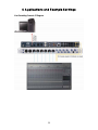
1
FIRESTUDIO
26x26 FireWire Recording System w/ Optical I/O
User’s Manual v.1.1
PreSonus Audio Electronics, © 2008
All Rights Reserved.
PreSonus Limited Warranty
PreSonus Audio Electronics Inc. warrants this product to be free of defects in material and
workmanship for a period of one year from the date of original retail purchase. This
warranty is enforceable only by the original retail purchaser. To be protected by this
warranty, the purchaser must complete and return the enclosed warranty card within 14 days
of purchase. During the warranty period PreSonus shall, at its sole and absolute option,
either repair or replace, free of charge, any product that proves to be defective on inspection
by PreSonus or its authorized service representative. To obtain warranty service, the
purchaser must first call or write PreSonus at the address and telephone number printed
below to obtain a Return Authorization Number and instructions of where to return the unit
for service. All inquiries must be accompanied by a description of the problem. All
authorized returns must be sent to the PreSonus repair facility postage prepaid, insured and
properly packaged. PreSonus reserves the right to update any unit returned for repair.
PreSonus reserves the right to change or improve the design of the product at any time
without prior notice. This warranty does not cover claims for damage due to abuse, neglect,
alteration or attempted repair by unauthorized personnel, and is limited to failures arising
during normal use that are due to defects in material or workmanship in the product. Any
implied warranties, including implied warranties of merchantability and fitness for a
particular purpose, are limited in duration to the length of this limited warranty. Some states
do not allow limitations on how long an implied warranty lasts, so the above limitation may
not apply to you. In no event will PreSonus be liable for incidental, consequential or other
damages resulting from the breach of any express or implied warranty, including, among
other things, damage to property, damage based on inconvenience or on loss of use of the
product, and, to the extent permitted by law, damages for personal injury. Some states do
not allow the exclusion of limitation of incidental or consequential damages, so the above
limitation or exclusion may not apply to you. This warranty gives you specific legal rights,
and you may also have other rights, which vary from state to state. This warranty only
applies to products sold and used in the United States of America. For warranty information
in all other countries please refer to your local distributor.
PreSonus Audio Electronics, Inc.
7257 Florida Blvd.
Baton Rouge, LA 70806
www.presonus.com
2
Table of Contents
1.) General Overview
1.1 Introduction ........................................................................................................4
1.2 Package Contents................................................................................................4
1.3 System Requirements ..........................................................................................5
2.) Installation and Hardware Overview
2.1 Installation (PC and Mac) ...................................................................................6
2.2 Hardware Controls and Analog/Digital Connections ..............................................8
2.3 Standalone Operation ..........................................................................................10
2.3 Quick Start Up with Cubase LE ..........................................................................10
3.) Control Console
3.1 Control Console - Overview ..................................................................................15
3.2 Control Console - Mixer ......................................................................................16
3.3 Control Console - Matrix Router ..........................................................................19
3.4 Hardware Settings ..............................................................................................25
4.) Applications and Example Settings
4.1 Expanding Your I/O ............................................................................................26
4.2 Live Recording ....................................................................................................27
4.3 Studio Recording ................................................................................................31
5.) Technical
5.1 Troubleshooting ..................................................................................................32
5.2 Technical Specifications ......................................................................................33
3
1 Overview
1.1 Introduction
Thank you for purchasing the PreSonus FIRESTUDIO. PreSonus Audio Electronics
has designed the FIRESTUDIO utilizing high-grade components to insure optimum
performance that will last a lifetime. Loaded with 24-bit 96K converters, eight
PreSonus microphone preamplifiers, SPDIF, Dual SMUX 96k ADAT, BNC
wordclock, and MIDI I/O, as well as the optional Monitor Station Remote, the
FIRESTUDIO is the most complete FireWire interface for professional quality
computer recording available today.
We encourage you to contact customer support at 1-225-216-7887 with any questions
or comments you may have regarding your PreSonus FIRESTUDIO. PreSonus Audio
Electronics is committed to constant product improvement, and we value your
suggestions highly. We believe the best way to achieve our goal of constant product
improvement is by listening to the real experts, our valued customers. We appreciate
the support you have shown us through the purchase of this product.
We suggest that you use this manual to familiarize yourself with the features,
applications and correct connection procedure for your FIRESTUDIO before trying to
connect it to your computer. This will hopefully alleviate any unforeseen issues that
you may encounter during installation and set up.
Thank you, once again, for buying our product and we hope you enjoy your
FIRESTUDIO!
1.2 Package Contents
•
FIRESTUDIO
•
Power Adapter
•
6’ FireWire Cable
•
Driver CD
•
Cubase LE CD
•
ProPak DVD
•
ProPak Complete DVD (additional software)
•
Users Manual
•
Warranty Card
4
1 Overview
1.3 System Requirements
Below are the minimum computer system requirements for your FIRESTUDIO.
Windows
- OS: Microsoft Windows XP SP1
- Computer: Windows compatible computer with FireWire port.
- CPU/Clock: Pentium, Celeron with 1.6Ghz or higher
- Memory(RAM): 512 MB (1 GB recommended)
Macintosh
- OS: MacOS X 10.4.x or later
- Computer: Apple Macintosh series with on-board FireWire port.
- CPU/Clock: PowerPC G4/Dual 1 GHZ or faster, all Intel-based Mac models.
- Memory(RAM): 512 MB (1 GB recommended)
Note that the speed of your processor, amount of RAM and size and speed of your
hard drive will greatly affect the overall performance of your recording system. Also, a
more powerful system (faster processor with more RAM) will allow for lower latency
(signal delay) that you might experience while monitoring audio or MIDI signals.
5
2 Installation and Hardware Overview
2.1 Installation
PC:
The following is a detailed procedure for installation of your FIRESTUDIO Drivers:
*YOU MUST INSTALL DRIVERS BEFORE CONNECTING YOUR FIRESTUDIO*
1.) Quit all currently running applications.
2.) Insert the Driver CD included with your FIRESTUDIO into your computer. (Do not
connect your FIRESTUDIO to the computer at this time).
3.) CD should auto run.* (If not, navigate to CD and double click on
FIRESTUDIO_Installer.exe)
*There are several parts to the installation of your
FIRESTUDIO. The installer will take you through
each step. Please read each message carefully as
the time at which you connect and power on your
FIRESTUDIO for the first time is critical to a
successful installation.
*If at any point during installation a “Software
Installation” message appears from Windows
regarding Windows Logo testing click “Continue
Anyway” to continue installation.
4.) When prompted to restart your computer, do so.
5.) Once the computer has restarted, connect your FIRESTUDIO to the computer via
FireWire and turn it on.
6.) A windows Found New Hardware Wizard should open. Select ‘No, not this time’,
when prompted to connect to the internet for Windows to find a driver. Click Next.
7.) The next window that comes up should identify the PreSonus Driver and allow you
to choose ‘Install Software Automatically’. Click Next.
8.) Click on Finish when the next window opens. You should now see a blue sync light
on your FIRESTUDIO, indicating that it is sync with your computer and ready to use.
Note: The FIRESTUDIO Control Console application can be found in the Start
Menu/ All Programs/ PreSonus Drivers/ FIRESTUDIO CPL.
6
2 Installation and Hardware Overview
Mac:
*YOU MUST INSTALL DRIVERS BEFORE CONNECTING YOUR FIRESTUDIO*
1.) Quit all currently running applications.
2.) Insert the Driver CD included with your FIRESTUDIO into your computer. (Do not
connect your FIRESTUDIO to the computer at this time).
3.) CD should auto run.* (If not, navigate to CD and double click on
FIRESTUDIO_Installer.exe)
*There are several parts to the installation of your FIRESTUDIO. The installer
will take you through each step. Please read each message carefully as the time
at which you connect and power on your FIRESTUDIO for the first time is
critical to a successful installation.
4.) When prompted with the Software License Agreement, click Continue, and then
click Agree.
5.) Select the destination volume to install the FIRESTUDIO software, typically
‘Macintosh HD’, and click Continue.
6.) Click on Install, and when the software installation is complete, click Close.
7.) You can now connect your FIRESTUDIO via the supplied FireWire cable and turn
it on. You should see a blue sync light on the FIRESTUDIO, indicating it is in sync
with the computer, and ready to use.
Note: The FIRESTUDIO Control Console software can be found in the
Applications folder (unless saved elsewhere), and is called ‘FIRESTUDIO’.
7
2 Installation and Hardware Overview
2.2 Hardware Controls and Analog/Digital Connections
Your FIRESTUDIO can simultaneously record/playback a total of 26 inputs and
outputs. The following will outline each connection type in detail from left to right on
the front and back panels:
Front Panel:
a.) 48 Volt Phantom Power: These two switches will activate phantom power for
microphone preamps 1-4 and 5-8 respectively. Phantom Power is only active
on the microphone XLR input.
b.) Neutrik Combo Connectors: These connectors can accept either 1/4” TS/TRS
or XLR inputs. Channels 1 and 2 feature an instrument level input on the 1/4”
connector for use as a Direct Injection input for guitar, bass, etc. Channels 3-8
accept line level input on the 1/4” connector. The XLR input on all channels
accepts microphone level input.
c.) Gain/Trim Controls: Each channel has its own gain/trim control and clip light.
The clip light will illuminate red when the preamp is clipping.
d.) Headphone Output: This headphone output can be assigned any output from
your DAW or the FIRESTUDIO Control Console, and has its own level control.
e.) Main Level: This level control will attenuate the Main Output on the back of
the FIRESTUDIO.
f.) Sync LED: This sync LED will illuminate RED when sync is NOT present and
BLUE when sync is present, indicating whether or not your FIRESTUDIO is
properly connected and installed to your computer, or properly synced to
another device (via ADAT, SPDIF, or BNC).
g.) Power Switch: This power switch will turn on/off power for the FIRESTUDIO.
Back Panel:
a.) Power Connector: This power connection allows the included power adapter to
screw tightly in, insuring that power is not accidentally disconnected from the
FIRESTUDIO.
b.) FireWire Ports: The included FireWire cable will connect to either port here
from your computer.
8
2 Installation and Hardware Overview
c.) MIDI I/O: The standard MIDI input and output allow connectivity of any MIDI
device to your FIRESTUDIO to be used in your DAW software.
d.) BNC Wordclock I/O: These standard BNC connectors allow you to connect any
device with BNC input or output to your FIRESTUDIO. This is to allow the
FIRESTUDIO to function as a master clock, or to slave to any other device.
e.) Dual SMUX Optical ADAT: These two inputs and outputs can be used to
connect any 96k Dual SMUX ADAT device via standard optical cable to the
FIRESTUDIO. These inputs and outputs can also function at 48k, allowing the
connection of one bank (8 channels) or two banks of ADAT (16 channels). For
more on how to use the optical ADAT I/O, please refer to section 4.1.
f.) SPDIF I/O: These RCA type connectors are for digital SPDIF connections up
to a 96k samplerate.
g.) RCA: This unbalanced RCA input is for use with any device with an analog
RCA output. This input is ONLY for use with the optional Monitor Station
Remote, and allows quick comparison of any other playback material with the
incoming input (ie; comparing your mix to a CD, etc).
h.) CAT-5 Connector: The optional MSR (Monitor Station Remote) connects here.
For more information on the MSR, please refer to the PreSonus website
(www.presonus.com).
i.) Main Out: This stereo TRS balanced output derives its output signal from your
DAW, the FIRESTUDIO Control Console software, or the optional MSR
remote. This output level is attenuated by the Main Level control on the front
panel.
j.) General Purpose Outputs: These stereo TRS balanced outputs can be used for
any purpose, and derive their output signal from your DAW, the FIRESTUDIO
Control Console software, or the optional MSR remote. There are no level
attenuators on the FIRESTUDIO for these outputs.
k.) Line Inputs 1 and 2: These are the 1/4” balanced line inputs for channels 1 and
2. These can be used with the preamp sends on channels 1 and 2 to insert an
external processor, or simply as line level inputs as found on channels 3-8 on
the front panel.
l.) Preamp 1 and 2 Sends: This TRS balanced output will output any analog
signal coming into the respective preamp BEFORE it is converted into digital
format and sent to your computer. This can be used to send the preamp signal
out to an external processor (ie; compressor, eq, etc), and back into the
respective line input for that channel, where it is then converted and sent to
your computer. These outputs are ONLY for channels 1 and 2 respectively.
9
2 Installation and Hardware Overview
2.3 Standalone Operation
Your FIRESTUDIO is capable of operating in Stand Alone mode without a computer.
The settings you make in the FIRESTUDIO Control Console application will be stored
in flash memory on the FIRESTUDIO itself, allowing you to disconnect the FireWire
connection from your computer and use any routing setup or hardware setting already
made.
Here’s an example:
If you are tracking a live show, you could route all of your inputs to analog or
digital outputs (using the FIRESTUDIO Control Console) to feed a hard-disk
recorder or other recorder for backup. If your computer stops working for any
reason, your backup recording will be unaffected, as all of the routing you’ve
created has been stored in flash memory in the FIRESTUDIO. This eliminates
the need for a more elaborate live recording setup involving splitter snakes, etc.
2.4 Cubase LE Quick Start Up
Use the included Cubase LE installation CD to install Cubase LE. Proceed through the
installation as it prompts you. Make sure to keep the CD envelope sleeve handy to
reference the serial number during installation.
1. Once Cubase LE is installed, launch Cubase LE. First you must set Cubase LE
to the FireStudio drivers. Click the Devices menu and then Device Setup.
10
2 Installation and Hardware Overview
2. Select VST Multitrack in the left column and then on the right side choose
“ASIO PreSonus” for the ASIO Driver.
3. Click Switch.
4. Now click the File menu and New Project. Choose “empty” template and a
“Destination Location” where your project will be saved to your computer.
11
2 Installation and Hardware Overview
5. Now click the Devices Menu and VST Inputs. Activate your additional input
channels clicking the graphic power buttons.
o Notice that the input channels are activated in pairs. Adding one audio
track is MONO. Meaning it will record from 1 input channel. It can be
switched to a STEREO track. Meaning it will look to record from 2 input
channels for a left and a right signal.
o Also, notice that your inputs are labeled for what they are. Mic/Inst,
Mic/Line, ADAT 1, ADAT 2 and SPDIF. The Aux ADAT channels are only
available when your FireStudio is set to 44.1k or 48k Sampling Rates.
6. Depending on the version of Cubase LE you have, there may be a limitation for
the maximum number of record-enabled input channels you can have active at
any time. Cubase LE 1.0.10 allows 8 active input channels. Other versions of
Cubase such as SL3 or SX3 do not have these limitations.
12
2 Installation and Hardware Overview
7. Now click the Project menu, Add Track and Multiple.
8. This will add multiple tracks. Choose Audio for Track and set your Count to the
number of audio tracks you want to add to your project.
9. Click Record Enable for each of your tracks. You will now notice a green level
bar indicating the audio track is receiving signal. You can also click the Input
Monitor if you want to monitor (listen to) the audio through Cubase while you
record. If you do, remember to turn off the Input Monitor button to playback
what you have recorded to your audio track. You can also monitor your input
signals with the FireStudio Control Console by creating a mix or routing inputs
directly to outputs.
13
2 Installation and Hardware Overview
10. Expand an audio track to reveal additional buttons. One is a Stereo/Mono
switch. Do this if you are recording a stereo source like the left and right
outputs of a keyboard or other stereo sound device.
11. Finally, click the record button on the Transport Bar to begin recording.
12. Click the Help menu and Documentations. There you will find the Getting
Started and the Operation Manual for Cubase LE. Use these to further
familiarize yourself with Cubase LE.
14
3 Control Console
3.1 Control Console -Overview
Please install the FIRESTUDIO drivers and open the FIRESTUDIO Control Console
before continuing through this section of the manual. A hands-on approach is very
helpful in learning all of the features the Control Console has to offer.
The Control Console has two main tabs, found at the top left of the window, ‘Mixer’
and ‘Outputs/Router’. Click on either tab to access the Mixer or Matrix Router.
Depending on your situation you may not need to use the Mixer or Matrix Router,
however, knowing how to use this software can greatly enhance your studio’s efficiency
and ease of use. Here’s a short list of what this software allows you to do:
•
Create multiple monitor mixes of all inputs and playback streams (ie; not
everyone in the band has to hear everything equally).
•
Send analog inputs to digital outputs, and vice versa. (ie; the FIRESTUDIO
can function as a standalone AD/DA with zero latency)
•
Create sends and returns for any input to incorporate external processors with
zero latency.
•
Give every input its own hardware output for incorporation into a larger studio
console or other recorder.
•
Send mixes out of several types of outputs simultaneously (TRS, ADAT,
SPDIF) to different devices for monitoring comparisons.
Note that ADAT channels 9-16 are not currently available in the FireStudio in the
Control Console. You cannot mix our route these channels with the FireStudio
Control Console. These channels may be monitored via your DAW software.
15
3 Control Console
3.2 Control Console - Mixer
The Control Console’s Mixer is a flexible and easy-to-use solution for creating multiple
mixes from your inputs and DAW playback streams, all with zero-latency. It is capable
of creating 9 independent stereo mixes of all of your inputs and playback streams, and
routing each mix to any stereo analog or digital output (except ADAT channels 9-16
when in 44.1k and 48k sample rates).
Great care has been taken to make this mixer look and ‘feel’ like hardware, so most of
the features will be familiar to an experienced engineer. The following describes the
layout of the Mixer and how it works:
•
The top row of tracks is colored in blue and includes all analog and digital
inputs.
16
3 Control Console
•
The bottom row of tracks is colored in grey and includes all playback streams
from your DAW software.
•
There are tabs at the very bottom of the window to access each mix 1-9. These
tabs can be renamed to anything you like by double-clicking on the name,
typing a new name, and hitting ‘enter’ on your keyboard.
•
In the upper right of the window there is a Mix File section with load and save
buttons. These buttons allow you to save the current mix of Mixer (one of the
nine stereo mixes), and then load that setup at any time. Below that are copy
and paste buttons which allow you to copy the settings for any mix and paste
them to another mix.
•
Below the copy and paste buttons is the stereo output track for the current mix,
with quick output routing buttons below it. You can select any and/or all
outputs for the current mix. Disengaging stereo output buttons reverts routing
to previous setting. If there is no previous setting or if the Control Console was
closed and then reopened, routing reverts to default.
17
3 Control Console
Note: All settings for the Mixer are stored in flash memory on the FIRESTUDIO, and
will be recalled each time the FIRESTUDIO is connected to the computer and the
Control Console is opened.
Track Elements
1. Pan Bar: This allows you to pan the track left or
right, and shows numeric readout of the current
setting.
2. Fader, Level Meter, Clip: Control and monitor the
level of the track. A red ‘C’ will illuminate when
the track has clipped (click on the ‘C’ to reset).
3. Link: Click on the word ‘Link’ in between two
tracks to put them in stereo mode. The faders for
each track will now move in unison and the pan
for each track will move far left and right
respectively. When the Link is disengaged, the pan
values will move back to their original positions.
4. dB value: Numeric readout of level in Decibels
below the fader/meter.
5. Mute, Solo: (‘M’, ‘S’) Mute or solo the track.
6. Name: You can name your track anything you like
by right-clicking in this space, typing a new name,
and hitting ‘enter’ on your keyboard (this name
will show up for this input/DAW playback stream
everywhere in the Control Console).
18
3 Control Console
3.3 Matrix Router
The Matrix Router allows you to create custom routing of inputs and playback streams
to any output for complete control of your studio. From simply routing a mix to a
stereo output, to AD/DA conversion on the fly, to every input and playback stream
having its own output, the Matrix Router can do it all quickly and easily. The
following describes the layout of the Router and how it works*:
•
On the far left of the window there are two tabs, ‘Inputs’ and ‘Playback’. These
tabs allow you to flip between views that list either the 18 inputs or 18
playback streams.
19
3 Control Console
•
Below the two tabs is the Router Preset section. You will see a Default button,
which sets the Router to a default state with all DAW returns routed to their
respective outputs (ie; DAW 1/2 out of analog 1/2, etc). The user can save any
routing scheme to any of the six presets by clicking on Save and then on the
number they wish to save to.
•
Below the Router Preset buttons are the source selectors for the Main Output,
and the headphone outputs (1 headphone output is on the front panel of the
FIRESTUDIO, the other 2 are on the optional MSR remote). These outputs
mirror the hardware outputs, so you can monitor what is outputting from any
given output pair (ie. quickly check a headphone mix you created for someone
else).
•
You can quickly audition any output pair through the main output or any of the
headphone outputs.
o For example, click on the word ‘Main’ and you will see it highlight in
blue. Now drag the mouse over any output pair to see a grey box with
the word ‘Main’ on it over the given output pair. Left-click to audition
what is being routed to that output through the Main output, and
double-left-click to assign the Main output to mirror that output pair.
•
At the bottom of the window are the tracks for each hardware output pair. The
Track Elements are identical to the assigned audio source except for LINK and
20
3 Control Console
MUTE. You will make these settings manually for the hardware output
channels.
•
The matrix is arranged in columns (vertical) and rows (horizontal). The
columns correspond to each hardware output on the FIRESTUDIO, and the
rows correspond to individual input or playback sources. You can select one
cell per column, and up to every cell per row.
•
When on the ‘Inputs’ tab, notice that the bottom row of the matrix includes a
‘quick selection cell’ for your playback streams. When on the ‘Playback’ tab,
notice that the top row of the matrix includes a ‘quick selection cell’ for your
input sources. When on either tab, the bottom row includes a ‘quick selection
cell’ for a Mix selection. Clicking on a ‘quick selection cell’ will drop down a
menu to choose the source for that cell.
21
3 Control Console
•
When the mouse is moved over any cell, you will see that cell highlight and
name what you are routing, with a small popup window that lists what output
you are routing to. Click on the cell to assign the routing for that source.
•
If you have routed a Mix to any output, that routing will be reflected in the
Output Router section of the Mixer for that mix.
•
Once everything is setup the way you need, we recommend creating a preset
using one of the six user definable Router Preset buttons. To create a preset,
left-click on Save, and then choose the number preset to which the current
setup will be saved. Then, click on any preset to restore its settings.
NOTE: All settings for the Matrix Router are stored in flash memory on the
FIRESTUDIO, and will be recalled each time the FIRESTUDIO is connected to the
computer and the Control Console is opened.
22
3 Control Console
CONTROL CONSOLE EXAMPLE SETTINGS
Example 1: All inputs routed to same channel outputs with optional Mix to SPDIF
L/R output.
Example 2: All analog inputs to same channel analog and digital outputs with optional
Mix to SPDIF L/R output.
Example 3: Analog input to digital outputs and digital inputs to analog outputs
(AD/DA).
23
3 Control Console
Example 4: All software (DAW) playback channels to all same channel Hardware
outputs.
Example 5: 8 channels of software (DAW) playback channels to 8 channels of analog
and ADAT outputs.
Example 6: 9 separate Mixes assigned to all FireStudio Hardware Outputs.
24
3 Control Console
3.4 Hardware Settings
Click on the Hardware Settings tab to access the following:
1.) Sample Rate (PC Only*): You can set the sample rate to 44.1, 48, 88.2, and
96k. When set at higher than 48k, the ADAT channel I/O is limited to 8
channels utilizing both ADAT ports and the Dual SMUX standard. A higher
sample rate will increase both the fidelity of the recording you will make and
the subsequent file size for every audio file.
2.) Buffer Size (PC Only*): You can set the buffer size from 64 to 1024 samples
per buffer. The buffer size will affect the latency (roundtrip time it takes audio
data to go into the computer and get processed back out to the FIRESTUDIO).
The lower the buffer size is set, the lower the latency will be, and the higher the
stress will be on your computer. Thus, if you experience digital ‘pops and
clicks’ in your audio playback, try adjusting the buffer size higher to reduce the
stress on your computer.
*When using a Mac and OSX, the sample rate can only be changed in
the Audio MIDI Setup Application. Buffer sized are changed in your
DAW.
3.) Clock Source: The clock source setting will determine where the FIRESTUDIO
is deriving its clock. Unless clocking to an external device, the clock source
should be set to Internal. You can choose between SPDIF, ADAT 1, ADAT 2,
or Word Clock when selecting an external clock source. The FIRESTUDIO will
sync to the samplerate the external device is set to when switched to any of the
external clock sources, and the sync light will be blue if it is in sync.
4.) Terminate BNC: Check this box to terminate the BNC Word Clock input. This
may need to be done to achieve stable sync depending on the external device
you are syncing to via BNC Word Clock.
5.) Reset Names: Clicking on this button will reset all user-defined names in the
Control Console.
25
4 Applications and Example Settings
4.1 Expanding Your I/O
You can easily connect additional microphone preamplifiers to expand your inputs and
outputs on your FireStudio via ADAT/SMUX optical light pipe connectors.
•
The DigiMax FS can connect to the FireStudio using 88.2k and 96k sample
rates via dual SMUX optical ADAT using 2 standard optical cables audio.
•
If you are recording with sample rate settings of 44.1k or 48k, you can connect
2 DigiMax FS’ to the FireSTudio for 16 additional preamp inputs and line
level outputs.
Note that ADAT channels 9-16 can only be assigned within your recording
software (DAW). You cannot mix or route the Auxiliary ADAT channels 9-16
in the FireStudio Control Console. Each DigiMax FS or other digital preamp
will connect with 1 optical cable at 44.1k or 48k.
•
You can also further expand your FireStudio by connecting to the Digital
SPDIF I/O. Two PreSonus Eureka channel strips can be connected using the
Eureka’s AD192 digital output card. Simply connect the SPDIF output on the
Eureka to the SPDIF input on the FireStudio for two additional microphone
preamplifiers.
NOTE: Any time you connect an external digital device you must make sure your
Master and Slave Clock Source settings are appropriate. Only 1 device can be the
Master device that will generate clock. Every other device connected must be
Slaved to the Master device. You must also make sure that Sampling Rate is set
the same for each connected device. See section 3.4 Hardware Settings above.
26
4 Applications and Example Settings
4.2 Live Recording
Live Recording Scenario 1: This setup scenario makes computer recording primary
to the P.A. system or House Mix. This setup scenario allows the FireStudio to
preamplify the signals that will be recorded by your computer and then mixed by
the Main Mixing Console or P.A. system.
1. Connect all audio sources to the FireStudio +/- DigiMax FS to be used as a
preamp and computer recording.
2. Route all input channels of the FireStudio to all outputs of same channels in
the FireStudio Control Console.
3. Connect all FireStudio +/- DigiMax FS outputs to Line Level input channels of
the Main Mixing Console or P.A. system.
NOTE: The routing of the FireStudio is zero latency and is saved in Flash Memory.
If communication is lost between the FireStudio and the computer, the FireStudio will
retain its routing settings and continue to pass audio. The signal to the Main Mixing
Console or P.A. system will never be interrupted. See section 2.3, Stand Alone
Operation.
27
4 Applications and Example Settings
Live Recording Scenario 1 Diagram
28
4 Applications and Example Settings
Live Recording Scenario 2: This setup scenario makes computer recording
secondary to the P.A. system or the House Mix. This setup will allow the Main
Mixing Console to preamplify the signals that will be mixed to the P.A. system and
then recorded by the computer.
1. Connect all audio input sources to the Main Mixing Console or P.A. system.
2. Connect the direct or AUX outputs of the Mixing Console to the Line Level
input channels of the FireStudio +/- DigiMax FS.
3. Anything you do with the FireStudio Control Console in setup scenario 2 will
be entirely for your own monitoring purposes while you are recording.
4. Note that changes made to the Mixing Consoles preamps will effect your
recording levels.
29
4 Applications and Example Settings
Live Recording Scenario 2 Diagram
30
4 Applications and Example Settings
4.4 Studio Recording
In the project or professional studio, the FireStudio is extremely powerful and flexible.
Here are a few typical set up examples.
Create separate headphone mixes for each musician
•
Setup your recording software (DAW) respectively to record your input
channels to individual tracks. Doing so is specific to your recording software
(DAW).
•
The FireStudio Control Console allows you to create up to 9 separate Mixes for
each of your artists in your studio. You can control what each of your artists
hear and what they want or need to hear.
•
For instance, the drummer might only want to hear the click track and a bass
guitar, while the vocalist may not want the drums in his headphones or
monitors.
•
Mix 1 might typically be your Control Room mix, the mix that the engineer
wants to hear. Mix 2-9 can be specific to each of your artists and can be
assigned to any hardware output of the FireStudio.
•
You can then connect headphone amplifiers and or monitors to the FireStudio’s
hardware outputs.
NOTE: you can assign a Mix to any Hardware Outputs with the Quick Output buttons
in each Mixer view and also in the Output/Router view. The Engineer can also
audition the audio for any hardware output. Reference audition feature outlined in
section 3.3 Matrix Router and see Example 7.
Mix “outside your computer” using a mixing board or summing mixer
•
Connect all hardware outputs of the FireStudio to the line level inputs of your
mixer board.
•
Then return the Main or an Aux L/R output of the mixer board to available
input channels of the FireStudio.
31
5 Technical
5.1 Troubleshooting
Please note that many technical issues can arise when converting a standard computer
into a DAW (Digital Audio Workstation). PreSonus will only provide support for
issues that directly relate to your FIRESTUDIO. It may be necessary to contact the
manufacturer of the computer, operating system and/or software to obtain additional
technical support. PreSonus does not provide support for issues in regards to
operating systems, additional hardware or software.
Please check our website, www.presonus.com regularly for software information and
updates, firmware updates, and technical support. Also, technical assistance may be
received by calling PreSonus at 225-216-7887 between the hours of 9 am and 7 PM
Central Standard Time, or by emailing [email protected].
When contacting technical support, please have the following information at hand:
•
What Operating System and version (ex; Mac OSX 10.4.7) are you running?
•
Have you successfully installed the FIRESTUDIO drivers on your computer?
•
What color is the sync light on your FIRESTUDIO when connected to the
computer via the supplied FireWire Cable and powered on?
•
Is the FireWire connection on your computer built-in (supplied on the
motherboard) or through a PCI/PCMCIA card?
•
What, if any, other FireWire Devices do you have connected to the computer?
•
What, if any, DAW software (Cubase, Logic, Sonar, etc.) are you using with
your FIRESTUDIO?
32
5 Technical
5.2 Technical Specifications
Microphone Preamp (XLR Balanced)
All measurements Microphone Input to Direct Output
Frequency Response (+0,- 0.5dB)
Frequency Response (+0/-3.0 dB)
Input Impedance
THD+N (unwtd, 1KHz @ +4dBu Output, Unity Gain)
EIN (unwtd, 55dB Gain, 150 Ohm Input, 20Hz to 22KHz)
S/N Ratio (Unity Gain, unwtd, Ref. = +4dBu, 20Hz to 22KHz)
Common Mode Rejection Ratio (1KHz, 55dB Gain)
Gain Control Range (+/-1dB)
Maximum Input Level (Unity Gain, 1KHz @ 0.5% THD+N)
Phantom Power (+/- 2VDC)
Instrument Input (1/4” TRS, Preamps 1 & 2)
Input Impedance
Line Inputs (1/4” TRS, Preamps 3 to 8)
All measurements Line Input to Direct Output
Frequency Response (+0,- 0.5dB)
Frequency Response (+0/-3.0 dB)
Input Impedance (Balanced)
THD+N (unwtd, 1KHz @ +4dBu Output, Unity Gain)
S/N Ratio (Unity Gain, unwtd, Ref. = +4dBu, 20Hz to 22KHz)
Gain Control Range (+/-1dB)
Maximum Input Level (Unity Gain, 1KHz @ 0.5% THD+N)
Insert Jacks (1/4” TRS)
Send Output Impedance (Unbalanced, Ring)
Return Input Impedance (Unbalanced, Tip)
Direct Outputs/DAC Outputs (1/4” TRS)
Output Impedance (Impedance Balanced)
Signal Level LEDs
Clip (+/- 0.5dBu)
Digital Audio
ADC Dynamic Range (A-wtd, 48KHz Sample Rate)
DAC Dynamic Range (A-wtd, 48KHz Sample Rate)
Bit Depth
Reference Level for 0dBFS
Digital Audio Output (2-Toslink™ Connectors, 8 channels)
Digital Audio Input (2-Toslink™ Connectors, 8 channels)
Internal Sample Frequency Selections (KHz)
External Sample Frequency Inputs
BNC Word Clock Output Level (75 Ohm load)
BNC Word Clock Input Level Range
Power
Input Voltage Range
Power Requirements (Continuous)
DC Input Connector Type = 5.5mm OD/2.1mm ID Barrel, Center Positive
External Switching Power Supply
Digital
Jitter Specification
33
20Hz to 50KHz
20Hz to 150KHz
1600 Ohm
< 0.003%
-126dBu
>101dB
>55dB
-6dB to 55dB
+17dBu
+48VDC
1 Mega Ohm
20Hz to 50KHz
20Hz to 150KHz
10 KOhm
< 0.003%
>101dB
-9dB to +12dB
+23dBu
51 Ohm
10KOhm
51Ohm
+18dBu
107dB
110dB
24
+18dBu
ADAT/SMUX
ADAT/SMUX
44.1, 48, 88.2, 96
BNC, ADAT
(SMUX),SPDIF
4.5V
3.0 to 5.5V
18 to 30VDC
24W
90-230VAC/35W
< 300 pS