1
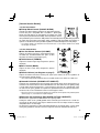
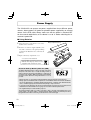
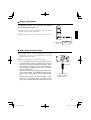
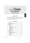
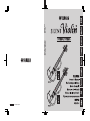
WT66620 R0 Printed in Japan
09_SV250_hu.indd 15
10.5.10 0:17:00 PM
SV250/SV255
English
Owner’s Manual
Congratulations!
Thank you for purchasing the Yamaha Silent ViolinTM. In order to obtain
the maximum performance and enjoyment from your Silent ViolinTM,
we urge you to read this Owner’s Manual thoroughly before using the
instrument. Please keep this Owner’s Manual in a safe place for later
reference.
■ SV250/255 Features
The SV250/SV255 Silent Violin™ is a high quality electric violin designed for
stage and studio use.
Based on the same slim body design found in previous Silent Violins™,
the SV250/255 incorporates a unique hollow structure in its body to deliver
enhanced acoustic tone and excellent playability.
The SV250/255 features a dual pickup design using one piezo-electric
pickup located underneath the bridge to reproduce the rich acoustic tone
produced by the overall instrument, and another newly developed piezoelectric pickup built into the bridge to accurately reproduce subtle bowing
nuances. Output from the two pickups can be blended freely to create a wide
range of tone. The instrument’s electronics are housed in a sturdy aluminum
control box that can be placed on the floor or attached to the player’s
apparel with its integral belt clip. The unit supplies the violin’s preamp with
its needed electric power and incorporates an equalizer for shaping the tone
of the instrument’s audio signal. It also includes a headphone monitor amp
with independently adjustable volume and the unit can be powered from any
one of three power sources; two AA batteries, a power adaptor, or phantom
power.
In addition to a regular monaural line out, an XLR balanced output provides
a noise resistant balanced output signal for sending the instrument’s output
directly to a mixing console. The two outputs let you easily connect to an
effector/amp system and mixing console at the same time, or connect to a
DAW via an audio interface for recording.
Crafted with high quality woods, quality construction and finish, plus
electronics designed specifically for the violin and diverse output options,
the SV250/255 goes beyond being a great instrument for practice to being
an instrument perfect for stage and recording use with its exceptional tone
quality and playability.
1
02_SV250_en.indd 1
10.5.10 11:23:35 AM
SPECIAL MESSAGE SECTION
This product utilizes batteries or an external power supply (adaptor). DO NOT
connect this product to any power supply or adaptor other than one described
in the manual, on the name plate, or specifically recommended by Yamaha.
This product should be used only with the components supplied or; a cart,
rack, or stand that is recommended by Yamaha. If a cart, etc., is used, please
observe all safety markings and instructions that accompany the accessory
product.
Battery Notice: This product MAY contain a small non-rechargeable battery
which (if applicable) is soldered in place. The average life span of this type
of battery is approximately five years. When replacement becomes necessary,
contact a qualified service representative to perform the replacement.
This product may also use “household” type batteries. Some of these may be
rechargeable. Make sure that the battery being charged is a rechargeable type
and that the charger is intended for the battery being charged.
SPECIFICATIONS SUBJECT TO CHANGE: The information contained
in this manual is believed to be correct at the time of printing. However, Yamaha reserves the right to change or modify any of the specifications without
notice or obligation to update existing units.
When installing batteries, do not mix old batteries with new, or with batteries of
a different type. Batteries MUST be installed correctly. Mismatches or incorrect
installation may result in overheating and battery case rupture.
Do not attempt to service this product beyond that described in the usermaintenance instructions. All other servicing should be referred to qualified
service personnel.
Warning: Do not attempt to disassemble or incinerate any battery. Keep all
batteries away from children. Dispose of used batteries promptly and as regulated by the laws in your area. Note: Check with any retailer of household type
batteries in your area for battery disposal information.
This product, either alone or in combination with an amplifier and headphones
or speaker/s, may be capable of producing sound levels that could cause
permanent hearing loss. DO NOT operate for long periods of time at a high
volume level or at a level that is uncomfortable. If you experience any hearing
loss or ringing in the ears, you should consult an audiologist.
Disposal Notice: Should this product become damaged beyond repair, or
for some reason its useful life is considered to be at an end, please observe all
local, state, and federal regulations that relate to the disposal of products that
contain lead, batteries, plastics, etc. If your dealer is unable to assist you, please
contact Yamaha directly.
IMPORTANT: The louder the sound, the shorter the time period before damage occurs.
NAMEPLATE LOCATION: The nameplate is located on the bottom of the
product. The model number, serial number, power requirements, etc., are
located on this plate. You should record the model number, serial number, and
the date of purchase in the spaces provided below and retain this manual as a
permanent record of your purchase.
NOTICE: Service charges incurred due to a lack of knowledge relating to
how a function or effect works (when the unit is operating as designed) are
not covered by the manufacturer’s warranty, and are therefore the owner’s responsibility. Please study this manual carefully and consult your dealer before
requesting service.
ENVIRONMENTAL ISSUES: Yamaha strives to produce products that are
both user safe and environmentally friendly. We sincerely believe that our
products and the production methods used to produce them meet these goals.
In keeping with both the letter and the spirit of the law, we want you to be
aware of the following:
Model Serial No.
Purchase Date
92-BP
PLEASE KEEP THIS MANUAL
FCC INFORMATION (U.S.A.)
1. IMPORTANT NOTICE: DO NOT MODIFY THIS
UNIT!
This product, when installed as indicated in the instructions contained
in this manual, meets FCC requirements. Modifi cations not expressly
approved by Yamaha may void your authority, granted by the FCC, to
use the product.
2. IMPORTANT:
When connecting this product to accessories
and/or another product use only high-quality shielded cables. Cable/
s supplied with this product MUST be used. Follow all installation
instructions. Failure to follow instructions could void your FCC
authorization to use this product in the USA.
3. NOTE:
This product has been tested and found to comply with the
requirements listed in FCC Regulations, Part 15 for Class “B” digital
devices. Compliance with these requirements provides a reasonable
level of assurance that your use of this product in a residential environment will not result in harmful interference with other electronic
devices. This equipment generates/uses radio frequencies and, if not
installed and used according to the instructions found in the user’s
manual, may cause interference harmful to the operation of other elec-
tronic devices. Compliance with FCC regulations does not guarantee
that interference will not occur in all installations. If this product is
found to be the source of interference, which can be determined by
turning the unit “OFF” and “ON”, please try to eliminate the problem
by using one of the following measures:
Relocate either this product or the device that is being affected by the
interference.
Utilize power outlets that are on different branch (circuit breaker or
fuse) circuits or install AC line fi lter/s.
In the case of radio or TV interference, relocate/reorient the antenna.
If the antenna lead-in is 300 ohm ribbon lead, change the lead-in to
co-axial type cable.
If these corrective measures do not produce satisfactory results, please
contact the local retailer authorized to distribute this type of product.
If you cannot locate the appropriate retailer, please contact Yamaha
Corporation of America, Electronic Service Division, 6600 Orangethorpe Ave, Buena Park, CA 90620
The above statements apply ONLY to those products distributed by
Yamaha Corporation of America or its subsidiaries.
CANADA
THIS DIGITAL APPARATUS DOES NOT EXCEED THE “CLASS B” LIMITS FOR RADIO NOISE EMISSIONS FROM DIGITAL APPARATUS
SET OUT IN THE RADIO INTERFERENCE REGULATION OF THE CANADIAN DEPARTMENT OF COMMUNICATIONS.
LE PRESENT APPAREIL NUMERIQUE N’EMET PAS DE BRUITS RADIOELECTRIQUES DEPASSANT LES LIMITES APPLICABLES AUX APPAREILS NUMERIQUES DE LA “CLASSE B” PRESCRITES DANS LE REGLEMENT SUR LE BROUILLAGE RADIO ELECTRI QUE EDICTE PAR
LE MINISTERE DES COMMUNICATIONS DU CANADA.
• This applies only to products distributed by Yamaha Canada Music Ltd.
• Ceci ne s’applique qu’aux produits distribués par Yamaha Canada Musique Ltée.
2
02_SV250_en.indd 2
10.5.10 11:23:35 AM
Your Silent Violin™ will give you years of reliable service if you follow the simple
rules given below:
■ Location
■ Handling and Transport
Do not expose it to the following conditions to avoid
deformation, discoloration, or more serious damage.
• Direct sunlight (e.g. near a window).
• High temperatures (e.g. near a heat source, outside,
or in a car during the daytime).
• Excessive humidity.
• Excessive dust.
• Strong vibration.
■ Power Supply
• Turn the power switch OFF when not in use.
• If you use an AC power adaptor, unplug the adaptor
from the AC outlet if not to be used for an extended
period of time.
• Unplug the AC power adaptor during electric storms.
• Avoid plugging the AC power adaptor into the
same AC outlet as appliances with high power
consumption, such as electric heaters or ovens.
Also avoid using multi-plug adaptors since these
can result in reduced sound quality and possibly
damage.
• Never apply excessive force to the controls,
connectors or other parts.
• Always unplug cables by gripping the plug firmly,
not by pulling on the cable.
• Disconnect all cables before moving the unit.
• Physical shocks caused by dropping, bumping,
or placing heavy objects on the unit can result in
scratches and more serious damage.
■ Cleaning
• Clean the cabinet and panel with a dry soft cloth.
• A slightly damp cloth may be used to remove
stubborn grime and dirt.
• Never use cleaners such as alcohol or thinner.
• Avoid placing vinyl objects on top of the unit (vinyl
can stick to and discolor the surface).
■ Electrical Interference
• This unit contains electric circuitry and may cause
interference if placed too close to radio or television
receivers. If this occurs, move it further away from
the affected equipment.
■ Turn Power OFF When Making Connections
• To avoid damage to the Silent Violin™ and other
devices to which it is connected (a sound system,
for example), turn the power switches of all related
devices OFF prior to connecting or disconnecting
audio cables.
YAMAHA is not responsible for damage
caused by improper handling or operation.
Information for Users on Collection and Disposal of Old Equipment and used Batteries
These symbols on the products, packaging, and/or accompanying documents mean that used
electrical and electronic products and batteries should not be mixed with general household waste.
For proper treatment, recovery and recycling of old products and used batteries, please take them
to applicable collection points, in accordance with your national legislation and the Directives
2002/96/EC and 2006/66/EC.
By disposing of these products and batteries correctly, you will help to save valuable resources and
prevent any potential negative effects on human health and the environment which could otherwise
arise from inappropriate waste handling.
For more information about collection and recycling of old products and batteries, please contact
your local municipality, your waste disposal service or the point of sale where you purchased the
items.
[For business users in the European Union]
If you wish to discard electrical and electronic equipment, please contact your dealer or supplier for
further information.
[Information on Disposal in other Countries outside the European Union]
These symbols are only valid in the European Union. If you wish to discard these items, please
contact your local authorities or dealer and ask for the correct method of disposal.
Note for the battery symbol (bottom two symbol examples):
This symbol might be used in combination with a chemical symbol. In this case it complies with the
requirement set by the Directive for the chemical involved.
3
02_SV250_en.indd 3
10.5.10 11:23:35 AM
Main Body/Accessories
After opening the packaging, please check that all the parts listed below are
included.
• Main Unit
(The instrument ships from the factory with its bridge lying flat.)
[SV250]
[SV255]
Bridge
• Control Box
Bridge
• Cable
(Connects the instrument
to the Control Box.)
• Cable Band x2
(Secures the cable to the
instrument body.)
• SUM-3 (AA) size
Manganese battery x2
• Stereo earphones
* The supplied battery is for
demonstration purposes.
• Owner’s Manual (this booklet)
* Use an optional Yamaha Power Adaptor (see page 15) for powering the instrument with a power adaptor.
4
02_SV250_en.indd 4
10.5.10 11:23:35 AM
Nomenclature
[Main Unit]
● Back
● Front
Tuning peg
Nut
Fingerboard
Neck
Neck
5th string (C) *SV255 only
4th string (G)
3rd string (D)
2nd string (A)
1st string (E)
Frame
Pickup Blend Control
(PICKUP BLEND)
Body
Bridge seat
Bridge
Control Box
Instrument Jack
Adjuster
Chin rest
Tailpiece
Shoulder
Rest Holder
The SV255 is used in the diagram.
5
02_SV250_en.indd 5
10.5.10 11:23:36 AM
[Control Box]
* For use with the SV250/SV255. Not compatible with other instruments.
Stereo Earphones
Belt Clip
Battery Indicator
Main Unit
Cable
Cable Hook
Phones Jack
Cable Hook
Instrument Jack
Phones Volume
Balanced Out Pad Switch
(BALANCED OUT PAD
-26dB/OFF)
Line Out Volume Control
(VOLUME)
Ground Lift Switch
(GROUND LIFT GND/LIFT)
Treble Control
(TREBLE)
Power Adaptor Jack
)
(DC IN 12V
Bass Control
(BASS)
Line Out Jack (Balanced)
(BALANCED OUT)
Power Adaptor
(Option)
Line Out Jack (Unbalanced)
(LINE OUT)
Electric Outlet
Connect to a balanced input
(XLR connector) on a mixing
console, audio interface, or
similar external device.
Connect to the input (standard
¼” phone jack) on a powered
speaker, effector, or similar
external device.
6
02_SV250_en.indd 6
10.5.10 11:23:36 AM
[Explanation of Input/Output Section]
<On the Instrument>
q
Control Box Instrument Jack
Cable
This jack is used to receive power from the Control Box
and transmit the audio signal from the instrument to the
Control Box. Use the supplied cable to connect the instrument to the “Instrument Jack” on the Control Box.
* A commercially available audio cable with stereo mini plugs
on both ends can also be used. (Cables with resistors are
Cable Band
not compatible.)
* The system will not operate properly if a monaural cable is
used.
Shoulder Rest Holder
* The system will not operate properly if the cable is attached
to anything other than the Control Box.
* Pass the cable end through the holes on the supplied cable band then attach to the shoulder rest
as shown in the diagram on the right to prevent accidental disconnecting of the cable.
Caution
• Disconnecting the cable while the power is ON may result in damage to the equipment. The
sudden shock to your ears may be severe, so please use caution.
• When connecting or disconnecting the cable, always make sure that the control box is not
connected to any external device, or that the power is switched OFF on the external device
before proceeding. The resulting loud sound may cause hearing loss and damage external
equipment.
• When connecting or disconnecting the cable, always make sure there are no inner earphones or headphones, etc., connected. The loud sound may cause hearing loss and damage the inner earphones or headphones.
<On the Control Box>
w
Instrument Jack (
)
Cable
This jack supplies power to the SV250/SV255 instrument and receives the audio signal from the SV250/
SV255. Use the supplied cable to connect the instrument to the “Instrument Jack” on the Control Box.
* The control box’s main power is switched ON when a cable
is connected to this jack.
* Hooking the cable onto the cable hook positioned furthest
away from the instrument jack prevents accidental disconnection of the cable.
Caution
Cable Hook
• Always disconnect the cable when the instrument is not in use. The instrument continuously consumes electric power when the cable is connected.
• When connecting or disconnecting the cable, always make sure that the control box is not
connected to any external device, or that the power is switched OFF on the external device
before proceeding. The resulting loud sound may cause hearing loss and damage external
equipment.
• When connecting or disconnecting the cable, always make sure there are no inner earphones or headphones, etc., connected. The loud sound may cause hearing loss and damage the inner earphones or headphones.
• Never connect any devices (including other Silent Violins™ with different model numbers)
other than the SV250/SV255 Silent Violin™ that is included in the bundled set.
Doing so may result in damage to the other device.
7
02_SV250_en.indd 7
10.5.10 11:23:36 AM
e
Phones Jack (
)
For connecting the supplied inner earphones.
* The headphone amp’s power is switched ON when a pair of stereo inner earphones is connected
to this jack.
* The volume level for the stereo inner earphones can be adjusted with the !0 PHONES VOLUME
control adjacent to the PHONES jack. Since the !0 PHONES VOLUME is not linked to the MAIN
VOLUME control, its level can be adjusted independently of the LINE OUT.
* Any commercially available headphones or inner earphones can be used.
Caution
• Always disconnect the headphones or inner earphones from the jack when the instrument
is not being used. The device continuously consumes power when a cable is connected to
the jack. Also, switching the power on when nothing is connected to this jack deactivates
the headphone amp decreasing power consumption to increase battery life.
• Never disconnect the headphones or inner earphones while the headphones or inner earphones are still in your ears. The resulting loud sound may cause hearing loss.
• Do not listen for extended periods of time at loud volume levels using the inner earphones
or headphones. Doing so can result in damage to your hearing.
r Line Out Jack (Unbalanced) (LINE OUT)
The line out jack is compatible with a standard ¼” phone
plug. The signal is delivered from this output after being
adjusted with the volume, treble, and bass controls.
t Line Out Jack (Balanced) (BALANCED OUT)
The balanced output jack is compatible with an XLR
connector. This jack delivers a balanced signal that is
the same as the LINE OUT jack (adjusted with volume,
treble, and bass controls).
The signal can be attenuated by 26dB using the BALANCED OUT PAD switch on the side of the control box.
Caution
• Make sure that the power is switched OFF or all volume levels are set to “0” on all external
equipment before connecting external equipment to the Line Out Jack (Unbalanced, Balanced). Loud volume levels can damage your hearing, and damage equipment.
• When making connections to external devices, make sure that the proper plugs are used
and securely connected.
• If the sound is distorted, use the volume control on the instrument or on the Control Box
and lower the volume until the sound is no longer distorted.
8
02_SV250_en.indd 8
10.5.10 11:23:36 AM
[Control Section Details]
<On the Instrument>
y Pickup Blend Control (PICKUP BLEND)
Controls the volume balance between the two built-in pickups.
The line out jack is compatible with a standard ¼” phone plug.
Rotate the knob fully to the right [BODY] to produce the signal
from the pickup underneath the bridge, which reproduces the rich
tone produced by the instrument’s body. Rotate the knob fully to the left [BRIDGE] to produce
the signal from the pickup in the bridge, which reproduces bow articulation and quicker response. Set the dial to its center position to produce a balanced output of the two pickups.
* The volume control is not located on the instrument itself, use the volume control on the control
box to adjust the volume.
<On the Control Box>
u Line Out Volume Control (VOLUME)
Adjusts the volume level of the signal delivered from
the LINE OUT and BALANCED OUT jacks. (It does
not effect the volume of the Phones jack.)
i Treble Control (TREBLE)
Adjusts the treble or high range frequencies. (Effects
all output)
o Bass Control (BASS)
Adjusts the bass or low range frequencies. (Effects
all output)
Cut
Boost
Cut
Boost
!0 Phones Volume (see diagram on page 7)
Adjusts the volume level of the Phones jack signal. (This volume can be set regardless of
the main volume control setting.)
* If the electric output sound is distorted, lower the VOLUME and other such controls to a suitable level.
!1 Ground Lift Switch (GROUND LIFT GND/LIFT)
Separates the ground between the instrument and external device when connecting the instrument to an external device via the BALANCED OUT XLR connector. The [GND] setting
is used under normal circumstances. If you experience noise due to a ground loop, move
the switch to the [LIFT] position to separate the ground between the instrument and external device. This is one method that can be used to suppress noise.
* When the switch is set to the [LIFT] position, the instrument will not operate with phantom power
(Refer to page 11). Use batteries or a power adaptor.
!2 Balanced Out Pad Switch (BALANCED OUT PAD -26dB/OFF)
Attenuates the signal from the BALANCED OUT jack by 26dB.
Setting this switch to the [-26dB] position when connecting the instrument to a small mixing console or other device that only has balanced XLR mic level inputs makes its output
compatible with a mic level input.
To connect the instrument to a line level balanced input on an external device, set the switch
to the [OFF] position to send the same level signal as that of the unbalanced LINE OUT.
9
02_SV250_en.indd 9
10.5.10 11:23:36 AM
Power Supply
The SV250/255 can operate on power supplied from three different power
sources; battery power, AC power, or phantom power supplied by an external
source via the XLR cable. Always make sure that the power is switched OFF
on the external audio device, or its volume is set to “0” before switching the instrument’s power ON.
■ Using Batteries
1
Open the battery compartment cover on the
backside of the control box.
2
Insert the two batteries supplied (SUM-3 (AA)
size). Take careful note of the polarity markings
as shown in the illustration above, and insert the
batteries.
3
Battery compartment cover
SUM-3 (AA)
size battery x2
Replace the battery compartment cover.
* For customers in the Netherlands
Bij dit produkt zijn batterijen geleverd.
Wanneer deze leeg zijn, moet u ze niet
weggooien maar inleveren als KCA.
About the Battery Warning Indicator (LED)
The Battery Warning Indicator located to the right of the instrument jack on the control box, is usually off during normal operation however, it will change from blinking to continuously lit
as battery power depletes. When the indicator starts blinking,
follow the cautions below and change the batteries as soon as
possible.
Battery Indicator
• Always follow the +/– signs when inserting the batteries. Improper insertion may result in fire.
• Always replace worn batteries with a complete set of new batteries. Never mix new and old batteries.
Do not mix different types of batteries (alkaline and manganese, or batteries from different manufacturers, or different types by the same manufacturer). Doing so may result in fire.
• To prevent possible damage to the unit due to battery leakage and unnecessary power drain, remove
the batteries from the unit when it is not going to be used for an extended period of time.
• The supplied battery is for demonstration purposes.
The warning indicator blinks once when connecting a cable to the jack if the batteries have an adequate charge or the power adaptor is operating properly. (When operating on phantom power alone,
the light will not flash when connecting a cable due to the control box design.)
10
02_SV250_en.indd 10
10.5.10 11:23:37 AM
■ Supplying AC Power
AC adaptor is optional, please purchase the optional
power adaptor (Refer to page 15).
1
Securely connect the power adaptor’s DC connector to the DC
IN jack on the side of the Control Box.
2
Plug the AC adaptor into a convenient wall AC power socket.
AC power
socket
Power
Adaptor
■ When Using Phantom Power
1
Use an XLR cable to connect the balanced out jack on the
instrument to a mixer or other external audio device that can
supply phantom power (48V).
2
Switch on the phantom power on the external device.
* Due to the supply limitations of phantom power, there is
not enough power to drive the headphone amp, so only the
amp for the line out jack and balanced out jack is operational regardless of whether a pair of inner earphones is
connected to the PHONES jack or not. (There is no output
from the PHONES jack.)
* When the instrument is powered using both phantom power
and the power adaptor, the headphone amplifier will operate since power supply priority is given to the power adaptor.
* The priority given to power use is power adaptor J phantom power J battery power, power is not drawn from the
battery when the power adaptor or phantom power is used.
XLR Cable
To an external device
capable of supplying
phantom power.
11
02_SV250_en.indd 11
10.5.10 11:23:37 AM
Set up
■ Tuning and Changing the Strings
Because the bridge includes a built in sensor,
which is connected to the body with a thin cable,
the instrument ships from the factory with the
bridge laying down. First, set up the bridge and
then proceed with tuning. As the strings get old,
sound quality will gradually decrease, and it will
become difficult to tune the instrument. Change
the strings as soon as you think they are getting
old.
D
G
A
Groove
1st string
4th string
SV250
D
G
C
Caution
• The end of the strings are sharp and can
cut fingers. Use caution when changing
strings.
• When changing or adjusting strings, do
not put your face close to the instrument.
The string may suddenly break resulting
in eye or other unexpected injuries.
• The lower side of the bridge supports the 1st string (E),
the higher side supports the 4th string (G)/5th string
(C). Make sure the bridge is placed properly, then set
the bridge in the bridge seat.
• Ensure that the bridge stands vertically. If it leans to
one side, use both hands to adjust. Make sure that
each string passes over the corresponding slits in the
bridge.
E
A
E
Groove
1st string
5th string
SV255
[Looking from the tailpiece]
Bridge seat
Bridge feet
[Make sure the bridge feet do not
come in contact with the bridge seat]
Bad
Correct Bad
Vertical
Body
Bridge seat
Tailpiece
[Bridge is placed vertically]
12
02_SV250_en.indd 12
10.5.10 11:23:37 AM
Make sure that the strings are resting in their appropriate grooves in the
bridge when playing the instrument.
Strings may come out of their grooves when adjusting the
bridge or changing strings. Since the 1st (E) and 4th (G)/5th
(C) strings tend to come out of their grooves easily, use
your fingers to hold the strings gently in place when tuning
the instrument.
Also, the 1st (E) string is fitted with a protective tube. Make
sure that the tube rests on the bridge.
Caution
Always make sure that the bridge is standing vertically, whether the instrument is being played or
stored. (see diagram on page 12)
Even if the bridge is standing vertically before tuning, it
may tilt during the tuning process. If so, readjust the bridge
so it stands vertically.
It is very important that the bridge stands vertically. If it
leans in either direction it will impair the sound and risk
damaging the instrument.
G
D
A
C
E
[Make sure that the strings do not
come out of their grooves]
Protective tube on
the 1st (E) string
[Bridge is placed vertically]
• String tunings are, 1st string E, 2nd string A, 3rd
string D, 4th string G, 5th string C (SV255 only).
Push in on the tuning peg and rotate to tune. Use a
piano, tuning fork, or tuner to tune the instrument.
3rd string (D)
• Finally, use the adjuster to fine tune the strings.
2nd string (A)
4th string (G)
Caution
If the adjuster is too loose, it could produce noise while playing.
1st string (E)
5th string (C)
SV255
Don’t loosen
too much.
• When the instrument is not going to be used for an extended period of time, loosen the strings until
the pitch drops a whole tone.
• Before using the instrument, make sure that the bridge is positioned vertically. Damage to the bridge
and poor sound quality may result if the bridge is not properly positioned.
13
02_SV250_en.indd 13
10.5.10 11:23:37 AM
● Winding the Strings
(Please refer to this section when changing the strings)
1
Before you string the instrument, set the adjuster so that it is in
the middle of its adjustment range. (All adjusters)
2
Place the ball (on the end of the string) in the notch on the adjuster. Make sure the ball is properly inserted in the adjuster’s notch.
String
The adjuster
should be set to
the middle of its
adjustment range.
Adjuster’s notch
Ball
3
Winding the 3rd,
4th and 5th strings
After threading the string through the hole in
the tuning peg, turn the tuning peg making one
wrap on one side of the hole and the remaining
wraps on the other side as shown in the diagram
on the right.
Remaining
winds
2nd string (A)
3rd string (D)
1st
wind
3rd string (D)
Winding the 1st and
2nd strings
1st
wind
Remaining
winds
2nd string (A)
4th string (G)
1st string (E)
4th string (G)
SV250
■ The Shoulder Rest
5th string (C)
1st string (E)
SV255
Shoulder rest
A commercially available violin shoulder rest (4/4
size) can be attached to the instrument.
* Some shoulder rests are incompatible (air cushion
type, etc.).
14
02_SV250_en.indd 14
10.5.10 11:23:37 AM
Specifications
Instrument
Neck
Body
Fingerboard/Tuning Pegs
Bridge
Frame
Tailpiece
Strings
Sensor
Power
String Length
Dimensions
Weight (instrument only)
Control
Maple
Spruce/Maple
Ebony
Maple (Built-in Sensor Type)
Synthetic Resin
SV250 : Adjuster : 4 pieces (Wittner)
SV255 : Adjuster : 5 pieces (Wittner)
Ball-end type violin strings (Zyex)
* Helicore on the 5-string SV255 only
Piezo pick-up (underneath the bridge),
Bridge w/ Built-in Piezo-electric Pickup
Supplied via the Control Box connection
328 mm (12-15/16”)
SV250 : 591 (L) x 206 (W) x 117 (H) mm
23-1/4” (L) x 8-1/8” (W) x 4-5/8” (H)
SV255 : 600 (L) x 206 (W) x 122 (H) mm
23-5/8” (L) x 8-1/8” (W) x 4-13/16” (H)
SV250 : approximately 500 g (1 lbs. 2 oz.)
SV255 : approximately 540 g (1 lbs. 3 oz.)
Pickup Blend
Control Box
Case
Controls
Connections
Power
Battery Life (Continuous Use)
Dimensions
(excluding the buttons)
Weight
Aluminum Alloy
• Line Out Volume
• Treble Control
• Bass Control
• Phones Volume
• Ground Lift Switch
• Balanced Out Pad Switch
• Instrument Jack (Input/Output with Built-in Power Switch)
• Phones Jack (Output, PHONES with Built-in Amp Power Switch)
• Line Out Jack (LINE OUT) (6.3mm Unbalanced Output)
• Line Out Jack (BALANCED OUT) (XLR Balanced Output)
• Power Adaptor Jack (DCIN12V)
SUM-3 (AA) size battery x2 or AC Adaptor
(YAMAHA AC Adaptor PA-3C, PA130A, PA130U :
700 mA)
DC12V,
Also Phantom Power (28-48V)
Using Manganese batteries :
When Using Earphones: approx. 15 hours, Without: approx. 45 hours
Using Alkaline batteries :
When Using Earphones: approx. 50 hours, Without: approx. 120 hours
142 (L) x 72 (W) x 49 (H) mm
5-9/16” (L) x 2-13/16” (W) x 1-15/16” (H)
approximately 260 g (9 oz.) (without supplied batteries)
Accessories
Cable, Stereo earphones, SUM-3 (AA) size Manganese battery x2,
Owner’s Manual (this booklet)
* Design and specifications are subject to change without notice.
15
02_SV250_en.indd 15
10.5.10 11:23:38 AM
WT66620 R0 Printed in Japan