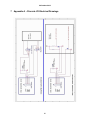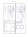
1
USER MANUAL
Ctek Z Series Cellular Routers
Models Z4200 and Z4400
Ctek – Things That Move Data
.
26 October 2012
Table of Contents
TABLE OF CONTENTS
I TABLE OF FIGURES
II PREFACE
1 1 INTRODUCTION
1 1.1 Theory Of Operation
1 1.2 Features
1 2 CONNECTORS, LIGHTS, SWITCHES, AND JUMPERS
3 2.1 Switches
3 2.2 Lights
3 2.3 Connectors (see figures 3 and 4 below)
4 3 START UP
6 3.1 Power
6 3.2 Connecting the Antenna
6 3.3 Connecting to the Ethernet Port – Administrative Connection
6 4 ADMINISTRATION, CONFIGURATION AND STATUS
7 4.1 7 Getting Started
4.2 Interfaces
4.2.1 Configuring The Wireless Interface
4.2.2 Configuring The Ethernet Interace
4.2.1 The RS232/RS485 Interface
4.2.2 Configuring The Relay Input Interface
4.2.3 Configuring The Relay Output (Driver) Interface
11 11 15 17 18 19 4.3 Status
4.3.1 Wireless Status
4.3.2 Ethernet Status
20 20 26 4.4 Services
4.4.1 Password Administration
4.4.2 Routing and Forwarding Services
27 27 27 i
26 October 2012
4.4.3 4.4.4 4.4.5 4.4.6 30 32 40 41 Tunneling Services
Serial Communications Services
Admin Screen Services
Wireless Activation Services (Z4200 CDMA Only)
4.5 Options
4.5.1 Applications
4.5.2 Tools
4.5.3 SIM Editor (Z4400 HSPA Only)
4.5.4 AT Commands (Z4400 HSPA Only)
46 46 46 46 48 5 SPECIFICATIONS
49 6 CERTIFICATIONS
49 7 APPENDIX A – DISCRETE I/O ELECTRICAL DRAWINGS
50 Table of Figures
FIGURE 1 - LIGHTS AND SWITCHES .................................................................................................................................................. 3 FIGURE 2 - DB9 CONNECTOR .............................................................................................................................................................. 4 FIGURE 3 – Z4200S MODEL CONNECTORS ....................................................................................................................................... 5 FIGURE 4 – Z4200U MODEL CONNECTORS ...................................................................................................................................... 5 FIGURE 5 - WINDOWS CONFIGURATION ......................................................................................................................................... 7 FIGURE 6 - LOGIN SCREEN .................................................................................................................................................................. 8 FIGURE 7 - Z4200 TOP MENU ............................................................................................................................................................... 9 FIGURE 8 - Z4400 TOP MENU ............................................................................................................................................................. 10 FIGURE 9 - Z4200 (CDMA) WIRELESS INTERFACE........................................................................................................................ 11 FIGURE 10 - Z4200 NETWORK SELECT ............................................................................................................................................ 12 FIGURE 11 - Z4400 (HSPA) WIRELESS INTERFACE ....................................................................................................................... 13 FIGURE 12 - ETHERNET CONFIGURATION..................................................................................................................................... 15 FIGURE 13 - RS232/485 CONFIGURATION ....................................................................................................................................... 17 FIGURE 14 - RELAY INPUT CONFIGURATION ............................................................................................................................... 18 FIGURE 15 - RELAY OUTPUT CONFIGURATION ........................................................................................................................... 20 FIGURE 16 - WIRELESS STATUS (Z4200) ......................................................................................................................................... 21 FIGURE 17 - WIRELESS STATUS DETAILS Z4200 .......................................................................................................................... 23 FIGURE 18 - WIRELESS STATUS Z4400 ............................................................................................................................................ 25 FIGURE 19 - ETHERNET STATUS ...................................................................................................................................................... 26 FIGURE 20 = PASSWORD ADMINISTRATION ................................................................................................................................. 27 FIGURE 21 - ROUTING AND FORWARDING ................................................................................................................................... 28 FIGURE 22 - ADVERTISING ................................................................................................................................................................ 29 FIGURE 23 - GRE TUNNELING CONFIGURATION ......................................................................................................................... 30 FIGURE 24 - A GRE TUNNEL .............................................................................................................................................................. 31 FIGURE 25 - SERIAL COMMUNICATIONS MENU .......................................................................................................................... 32 FIGURE 26 - TCP PAD CONFIGURATION ......................................................................................................................................... 33 FIGURE 27 - UDP PAD CONFIGURATION ........................................................................................................................................ 38 FIGURE 28 - PPP CONFIGURATION .................................................................................................................................................. 39 FIGURE 29 - ADMIN SCREEN CONTROL ......................................................................................................................................... 40 FIGURE 30 - SPRINT ACTIVATION ................................................................................................................................................... 41 ii
26 October 2012
FIGURE 31 - VERIZON WIRELESS ACTIVATION ........................................................................................................................... 42 FIGURE 32 - ACTIVATION CONTROL .............................................................................................................................................. 42 FIGURE 33 - ACTIVATION LOG ......................................................................................................................................................... 43 FIGURE 34 - MANUAL ACTIVATION ................................................................................................................................................ 44 FIGURE 35 - SPRINT PRL UPDATE .................................................................................................................................................... 45 FIGURE 36 - USER DEFINED APPLICATIONS ................................................................................................................................. 46 FIGURE 37 - SIM MANAGEMENT ...................................................................................................................................................... 47 FIGURE 38 - AT COMMAND INTERFACE ........................................................................................................................................ 48 iii
26 October 2012
Preface
Welcome to the Ctek Z Series Cellular Router User’s Guide. This manual covers the Z4200 EVDO and the Z4400
UMTS/HSPA router. The User’s Guide will explain the basic operation of the router and take you through the necessary
settings to get your wireless application online. Additional information and applicable technical notices can be found at
www.ctekproducts.com.
Note that all administrative functions and screens on the two models are identical with the exception of the Wireless
Status and Wireless Interface screens, and the Z4200's Activation screen which is replaced on the Z4400 by a SIM Tools
menu item.
1 Introduction
Wireless routers provide application and network designers with a bridge between the world of IT infrastructure and the
evolving wireless M2M networks. With the Z Series the wireless transport is fully integrated into the product’s routing
fabric meaning that you can approach the setup and operation of this product much as with any other IP addressable
device. Wireless considerations are reduced to the absolute minimum necessary to register and make connections on a
network.
A number of optional controllers are available for use with the models covered in this manual including a micro amp
standby power controller, an analog/digital I/O controller, and a relay power controller. The operation of these devices is
covered in their specific user manual and in applicable TechNotes.
1.1
Theory Of Operation
The Z Series router is a complete IP router that routes traffic over LAN Ethernet (10/100baseT) connections. The wireless
features of the router simply extend the IP routing capabilities to include routing and network address translation (NAT)
over cellular wireless networks. As with most routers Ctek’s Z Series can be viewed as having a Local Area Network
(LAN) side and a Wide Area Network (WAN) side. Traffic originating at the router’s Ethernet or Serial port is considered
LAN traffic. The Wide Area Network connection is over the wireless network’s 1XRTT transport.
1.2
Features
This manual covers Ctek Z Series and contains the following feature and functions.
1) Ethernet
a. Static Addressing
b. Dynamic (DHCP) Server
c. Configurable DNS address
d. Configurable Gateway, Sub net mask, and Broadcast address
e. Port Forwarding
f. Service management
2) Wireless Interface
a. Enable/Disable WAN Interface
b. Enable/Disable inbound IP requests
c. DDNS Interoperability with Ctek's enhanced UDP interface
d. DDNS Interoperability with BIND or MS Server
e. Administration web server port address selection
f. Enhanced network activation (Z4200)
g. Home Network Selection
1
26 October 2012
3) RS232 (DB9 serial port)
a. Configurable Bit Rate
b. Configurable for Start/Stop Bits, Flow Control, and Parity
c. Local and remote Telnet Access
d. TCP/UDP Packet Assembly and Disassembly (PAD) function.
e. PPP Interface
4) RS485 Auxiliary Serial Port
a. Configurable Bit Rate
b. Configurable for Start/Stop Bits, Flow Control, and Parity
c. TCP/UDP Packet Assembly and Disassembly (PAD) function.
5) USB Host Connection
6) Relay Contact Closure (detection and operation)
a. NO/NC detection
b. SMS or email cry out alarm
7) Relay Driver Output ( Maximum sink current 200ma @24V)
a. SMS Activation
b. Web Activation
8) General Administration
a. Modify User and Password
9) Status – Ethernet Status
a. Currently Assigned IP Address
b. Current MAC Address
10) Wireless Status – CDMA or HSPA/UMTS Status
a. ESN or IMSI
b. Network Assigned IP Address
c. Telephone Number (MIN) or MSISDN
d. Current Network Status Active/Inactive
e. Signal Level (RSSI)
2
26 October 2012
2 Connectors, Lights, Switches, and Jumpers
2.1
Switches
Referring to Figure 1, there are two switches on the front of the Z Series router. S1 (Reset) causes a hard reset of unit.
S2 (DFLT) is used to completely restore the firmware settings that were included when the product was shipped from the
factory. To restore factory defaults, the unit must be running. You should wait a full two (2) minutes after booting or
powering on the unit before restoring factory defaults. After waiting two minutes press the Restore Defaults (inner) switch
and hold it down for 10 seconds. After 10 seconds, you will see both the green and yellow lights go off. At that time you
may either press the reset (outer) switch or cycle power on the unit.
Figure 1 - Lights and Switches
2.2
Lights
The Z Series router has indicators as shown in Figure 1.
LAN – The LAN light indicates that the Ethernet port is connected to an active Ethernet device.
The network status indicators LINK and SVC are interpreted as follows:
SVC – Multi-color (yellow/green). Indicates:
a) Power
b) RSSI
Display
Definition
Off
Yellow Blinking
Yellow Solid
Green Solid
No Power
Power On – No Signal (RSSI)
Power On – RSSI < -88
Power On – RSSI >= -88
3
26 October 2012
Link - Multi-color (red/green). Indicates:
a) Status of IP connection
b) Type of transport (EV-DO or 1xRTT)
2.3
Display
Definition
Off
Green
Red
No Connection (IP address)
Connection established on 1xRTT or GPRS
Connection established on EV-DO or HSPA
Connectors (see figures 3 and 4 below)
RS232 Connector – This connector is a standard RS232 DCE interface. A straight-through RS232 cable should be used.
The RS232 connector pin out diagram is shown below.
Figure 2 - DB9 Connector
Ethernet Connector
The Ethernet connector on the Z Series is a standard RJ45 connector with auto polarity sensing and can be used with
either a standard Ethernet cable or a reverse (cross over) Ethernet cable.
Terminal Block
Connector J1 supports four separate functions, power, relay contact closure detection, relay driver output, and auxiliary
RS-485 serial port serial data. Contact closure pins 2 and 4 are shared with the auxiliary serial port. To option remove the
circuit board and locate 3-pin headers JP1 & JP2 behind the green connector. Facing the end of the board containing the
green connector JP1 and JP2 should have jumpers center to right to use the discrete I/O (Din, Dout), and JP1 and JP2
should have jumpers center to left to use the auxiliary RS-485 serial port. Auxiliary serial port parameters (baud, parity,
etc.) are set using the RS232/485 configuration screen. From the factory the unit ships with the auxiliary RS-485 serial
port enabled and configured as a master device.
.
4
26 October 2012
The J1 pin out configuration is as follows:
Terminal Block Pin
JP1 & JP2 (internal) Center to Right
JP1 & JP2 (internal) Center to Left
Pin 1
Pin 2
Din Src – Discrete Input Source
Din – Discrete Input (See Appendix A)
TR- of RS-485 auxiliary serial port
Pin 3
Dout Gnd – Discrete Output Ground
Ground of RS-485 auxiliary serial port
Pin 4
Dout - Discrete Output
Power supply Ground
Power supply +12VDC
Pin 5
Pin 6
3
1
TR+ of RS-485 auxiliary serial port
Power supply Ground
Power supply +12VDC
1
Notes
Note 1
Note 2
Note 3
Connect a 120 ohm resistor across pins 2 --> 4 for multi-drop configurations
Available as a third wire ground for use in noisy environments
Discrete output is rated at 200ma @ 24 volts maximum sink current
Figure 3 – Z4200S model connectors
Figure 4 – Z4200U model connectors
5
2
26 October 2012
3 Start Up
Warning – You must connect antenna(s) to the SMA style antenna connectors on the router before turning it on.
Failure to do this could result in erratic start up behavior and could possibly damage the unit.
Note – Z Series routers ship from the factory with DHCP server enabled. The Default Gateway address for the
unit is 192.168.1.10. The address of the web based administration is also 192.168.1.10. After you have activated
your unit on the wireless network it WILL NOT have a DNS address, meaning that public Internet web access will
not work. To load DNS values go to the Ethernet Interface screen, select “Acquire From Wireless Network” and
press the update button. At this point the Primary and Secondary DNS addresses in the Ethernet Interface screen
will be populated with the DNS addresses provided by your wireless network. As a last step restart both the
router and the connected PC.
3.1
Power
Before starting connect the supplied 12VDC power adapter to the power connector described in Section 2. The adapter
supplied with your router is suitable for use with 120VAC 60-hertz wall power. If you need a different power solutions
contact Ctek.
3.2
Connecting the Antenna
Antennas should be attached to the SMA style antenna connectors described in section 3. The antenna must be
connected before powering the unit on. ON the Z4200 the antenna connector to the right of the LAN LED is the primary
(transmit/receive) antenna and the connector to the left of the reset button is the secondary or diversity antenna.
3.3
Connecting to the Ethernet Port – Administrative Connection
For a direct Ethernet connection between a PC connect to the Ethernet port using a standard or reverse Ethernet cable.
For initial configuration and administration with a PC or workstation Ctek recommends that the PC be set to obtain an IP
address and obtain a DNS address automatically. For Windows PCs make the following settings under the networking
control panel
6
26 October 2012
Figure 5 - Windows configuration
4 Administration, Configuration and Status
About Addressing – Devices connecting to cellular networks are assigned an IP address by the serving network.
Address assignment may either be static or the unit will be dynamically assigned an IP address, depending on
arrangements that you have made with your wireless network operator. Dynamically assigned IP address remain in effect
for a period of time assigned by the network operator, usually at most a small number of hours.
Ctek’s Z Series includes features that manage the temporal nature of dynamically assigned wireless IP addresses. Using
the Wireless Configuration screen you can configure your router to use a Dynamic DNS (DDNS) service. Ctek operates a
DDNS test bed that allows our customers to observe the performance and reliability of DDNS with their applications. For
large-scale commercial applications Ctek recommends that users configure their own DDNS, managed and maintained
with the customers ongoing IT operations. The Z Series may also be configured to operate with a standard DNS having
Dynamic DNS capabilities. Examples of this type of service would be Berkeley Internet Name Daemon (BIND) and Microsoft
Server 2000 and up. For detailed information see Ctek’s TechNote S001.
Even if you elect to use a static IP address a DDNS service will add value in two ways. First, when the networks static
addressing assignment fails there is a mandatory waiting period before the endpoint is allowed to reinitiate the request for
a static address registration. During this period of time the network will dynamically assign addresses to the end point. A
DDNS service will make the end point network addressable (by name) during this period of time. Secondly, a name
service allows your end point to be known by a name that is independent of network addressing. Addressing a unit by
name may be easier for end users to remember and will, over a long period of time, reduce maintenance problems.
4.1
Getting Started
Once the PC has been set up properly and physically connected to the router you are ready to begin configuring the
router for your application. To access the Administration menu use any web browser pointed at http:// 192.168.1.10. A
login screen appears as shown below. The default User ID is “ctek” (without the quotes) and the default Password is also
“ctek”. Be sure to change the user ID and password and record your new selections.
7
26 October 2012
Figure 6 - Login Screen
When you have completed the login process you will be presented with the top-level administration menu. Both the Z4200
and Z4400 top level menus are shown below.
8
26 October 2012
Figure 7 - Z4200 Top Menu
9
26 October 2012
Figure 8 - Z4400 Top Menu
Note that the administration menu is divided into four sections. The Interfaces section deals with physical connectivity,
managing the connection and subtended devices. Status screens are provided for the wireless and Ethernet interfaces.
Services are applications that are within the router core to modify the behavior of a specific interface or to change system
wide parameters within the router core. Under the Options category users can find any optional or custom applications
and tools provided to maintain the router.
Important Note – The Restart button must always be used to apply any changes made on specific
Interface or Service screens.
10
26 October 2012
4.2
Interfaces
4.2.1 Configuring The Wireless Interface
The configuration screen for the Model Z4200 (EVDO and 1xRTT) wireless interface is shown below in Figure 8 and
described in the text following. Figure 10 and its associated text describes the wireless interface provided with the Model
Z4400 for use on HSPA, UMTS, GPRS, and EDGE networks.
Figure 9 - Z4200 (CDMA) Wireless Interface
Network Select – Note: This setting should only be changed after consulting with Ctek Support. This pull down
menu allows the user to control the home network setting of the CDMA connection, effectively limiting the scope of the
Preferred Roaming List (PRL) assigned by your wireless network operator. The possible settings are shown below. The
EV-DO choices are only available on the Z4200.
11
26 October 2012
Figure 10 - Z4200 Network Select
User Name and Password – Required for activation on some networks. See TechNotes for specific usage.
Wireless Connection – Used to enable/disable the wireless WAN connection.
Disabled – Turn off WAN connection
Enabled – Turn off WAN connection
Use Network’s Dynamic IP Address – For most networks this will be the correct selection.
Use The Following Static IP Address – If your selected network is capable of provisioning a static IP address to your
application check this box and enter the assigned IP address. See TechNotes for network specific set up.
Enable LCP echo packets – Used on some International networks. For all US networks LCP echo packets should be
turned off, meaning this box should be unchecked. If you have questions check with Ctek support.
Select DNS Type – Used to select the appropriate protocol for your Dynamic DNS.
1)
2)
3)
4)
None – DDNS will not be used.
EW/SMS – Use Ctek Enhanced Wireless DDNS with SMS updates.
EW/UDP - Use Ctek Enhanced Wireless DDNS with UDP updates over the EV-DO/1XRTT Air Interface
Standard UDP – Use a standard BIND, MS2000, or MS2003 DDNS server
Device Name – Establishes the name by which this particular router will be known at the Name Server. This entry must
be a fully qualified device name and domain and is limited to 40 characters in total. It is limited to one level of name space
definition meaning that all characters to the right of the first “dot” will be assumed to be a component of the resolving
server. An example would be ctek01.thingme.net where ctek01 is the name of an individual router and thingme.net is the
name of the resolving server.
Primary and Secondary Name Server – Enter the IP address of the designated Name Server. Name resolution is not
performed on this entry meaning that a numeric IP address of the resolving server is required.
12
26 October 2012
Provide Network Name Server Facilities – Selecting Yes causes this router to provide Name Server services to client
Ctek routers configured to use it. If this option is selected additional set up in the Name Services screen will be required.
Figure 11 - Z4400 (HSPA) Wireless Interface
Network Select – Available settings are Automatic, Prefer A Network, or Demand a Network.
Automatic – Allow radio to select network based on SIM and signal quality
Prefer a Network – Similar to Automatic with a bias towards the network ID specified in the Network ID field
Demand a Network – Make every effort to use the network specified in the Network ID field
User Name and Password – Normally blank. Required for activation on some networks. See TechNotes for specific
usage.
Wireless Connection – Used to enable/disable the wireless WAN connection.
Disabled – Turn off WAN connection
Enabled – Turn off WAN connection
13
26 October 2012
Inactivity Timer – Used to specify a duration of no outbound or incoming traffic after which the WWAN connection will be
re-established.
APN – Provided by the network operator. Determines what IP addresses are assigned to the mobile station, what security
methods are used, and how the GSM data network connects to the customer’s network.
PDP Address – Provided by the network operator. Specifies the address of a particular device’s Packet Data Protocol
context area in the network.
Authentication – Available settings are None, PAP, CHAP, BOTH. Usually set to none but may be required on some
networks.
Enable LCP echo packets – Used on some International networks. For all US networks LCP echo packets should be
turned off, meaning this box should be unchecked. If you have questions check with Ctek support.
SMSC Address – Short Message Service Center Address. A number prefixed with a plus (+) sign that specifies the
service center that will handle SMS traffic. Provided by the network operator.
Email Gateway – A number (address) specifying a gateway that will transform email to SMS and SMS to email. Provided
by the network operator. Note that emails targeted at SMS delivery have network dependent formats.
Select DNS Type – Used to select the appropriate protocol for your Dynamic DNS.
1)
2)
3)
4)
None – DDNS will not be used.
EW/SMS – Use Ctek Enhanced Wireless DDNS with SMS updates. Not currently supported.
EW/UDP - Use Ctek Enhanced Wireless DDNS with UDP updates over the GPRS/EDGE Air Interface
Standard UDP – Use a standard BIND, MS2000, or MS2003 DDNS server
Device Name – Establishes the name by which this particular router will be known at the Name Server. This entry must
be a fully qualified device name and domain and is limited to 40 characters in total. It is limited to one level of name space
definition meaning that all characters to the right of the first “dot” will be assumed to be a component of the resolving
server. An example would be ctek01.thingme.net where ctek01 is the name of an individual router and thingme.net is the
name of the resolving server.
Primary and Secondary Name Server – Enter the IP address of the designated Name Server. Name resolution is not
performed on this entry meaning that a numeric IP address of the resolving server is required.
Provide Network Name Server Facilities – Selecting Yes causes this router to provide Name Server services to client
Ctek routers configured to use it. If this option is selected additional set up in the Name Services screen will be required.
14
26 October 2012
4.2.2 Configuring The Ethernet Interace
The Ethernet configuration determines how devices connected to the LAN side of router will be addressed, and what the
actual address of this router will be on the LAN.
Figure 12 - Ethernet Configuration
Media Type – Determines the type of Ethernet connection. Auto allows router to determine what the connection is. This
setting is appropriate for most cases. Other settings are to select either 10Mb (10baseT), 100Mb (100baseT), Full Duplex
(FD), or Half Duplex (HD). Again, in almost all cases Auto will correctly determine the proper setting.
DHCP Configuration – These settings determine the network topology of the LAN side of router’s network.
Disabled – You must manually configure the IP address and other addressing parameters described in the next
section . It is recommended that the router be assigned a private static address of 192.168.1.10.
Enable Server - This router must be assigned a private static IP address, as defined in the next section. It is
recommended that an address of 192.168.1.10 be used. The DHCP server will issue dynamic IP addresses to
other devices connected to the LAN side. IP addresses will be assigned for up to 50 devices. Address assignment
is sequential in the range of 192.168.1.100 – 192.168.1.150.
Enable Client – Some other device on the LAN side of the network is acting as a DHCP server. The router will be
assigned a dynamic IP address by the DHCP server.
DNS Address Source – In most cases this parameter should be set to Acquire From Wireless Network. In this case,
when you click on the Update button, the router will verify that it has been connected to the wireless network and that the
15
26 October 2012
wireless network has provided DNS addresses. If DNS addresses have been provided, they will be displayed in the
Primary and Secondary Address boxes. If addresses have not been provided, you will receive an error indication. At that
point, you should allow the router to establish a connection with the wireless network so that it can acquire the DNS
addresses. You should then go back into the Ethernet Configuration screen and click on submit again. At this point, the
DNS addresses should appear.
If you application requires a specific DNS setting check the User Defined box and manually fill in the DNS IP Address
fields below.
DNS IP Address (Primary and Secondary) – The address of the Domain Name Server that your network uses. This
should not be confused with the Name Server entries on the Wireless Interface screen. The DNS referenced by these
addresses will resolve outbound queries.
IP Address – The IP address assigned to the LAN segment of this router.
NetMask – This parameter is also known as Subnet Mask. Network Mask determines which portion of an IP address is
the network portion and which portion belongs to the host. As an example a setting of 255.255.255.0 would indicate that
the first three groups of this address (255.255.255) identify the network and that the last group (000 – 254) identify a
particular host.
Default Gateway – The Default Gateway is the address of a device that the router will use to reach remote networks or
servers through its wireless WAN. In a normal situation where the Z4200/Z4400 is acting as a edge router and is expected
to pass incoming Ethernet traffic through to the wireless network, this field should be left blank.
Broadcast Address
If applications on the router need to do a broadcast operation, this is the address that will be used on the Ethernet
segment to fulfill the broadcast request.
16
26 October 2012
4.2.1 The RS232/RS485 Interface
This screen sets basic parameters for the RS232 port and the auxiliary serial port. These settings should be made to
correspond to those on the far end of the serial connection or serial over IP emulation. The RS232 and RS485 serial ports
are available for all applications and can be connected to the TCP or UDB PAD feature. In addition the RS232 port can be
configured to establish a Point-To-Point Protocol (PPP) connection over a serial link.
Figure 13 - RS232/485 Configuration
Bit Rate – Selects transmit and receive speed. This setting is available on both the RS232 and RS485 ports.
Character Length – Selects the number of bits representing a character. This setting is available on both the RS232 and
RS485 ports.
Parity – Selects the parity bit setting that will match the far end. This setting is available on both the RS232 and RS485
ports.
Flow Control (DB9 Only) – Selects No flow control, Hardware Flow Control (RTS/CTS), or Software Flow Control
(XON/XOFF). If RTS/CTS is selected make sure that the cable you are using has those pins connected on both ends.
Many pre-manufactured cables either do not terminate these signals or else jumper them into a permanent True state.
17
26 October 2012
Service – determines the mode of operation for the serial ports. Services may be in operation on both serial ports
simultaneously.
None - Indicates that a custom application and protocol has been implemented.
TCP PAD & UDP PAD - Selects the appropriate Packet Assembly and Disassembly Service.
PPP - Establishes a PPP connection over the RS232 link
4.2.2 Configuring The Relay Input Interface
This screen configures the connection characteristics of the relay input interface and defines the service associated with
this interface. Currently, the relay interface can cause an SMS message to be sent to one or more wireless devices or an
e-mail message to be sent to one or more email addresses. The rules and limitations that apply to multiple phone
numbers or email addresses are described below.
Appendix A contains schematic information concerning the relay input configuration.
Figure 14 - Relay Input Configuration
Relay Input Trigger – Establishes the conditions under which the Relay Service will be invoked. Unless it is disabled the
relay input is sampled at 1000 millisecond (1 second) intervals.
Disabled – Never respond to relay activity
On Closure – Respond when relay contacts go closed
On Opening - Respond when relay contacts go open
Maximum Trigger Rate – This setting determines how often the router will send a “relay event” message. If the relay
event is recurring at a rapid rate this setting will prevent an undesirable “flood” of messages. If Maximum Trigger Rate is
set to "Always" the relay input is operating in edge triggered mode. In this mode the router will invoke its assigned
service any time that the input transitions to the selected state. So if ON CLOSURE is selected an SMS is sent every time
that the contacts close. This means that once closure is sensed there can be no other closure event until the contacts are
first sensed to be open.
18
26 October 2012
All other modes where Max Trigger Rate has a time value are level sensitive. So if the contacts close an SMS is sent and
then the state of the relay input is ignored for a defined period of time. For instance, if Max Trigger Rate is set to 5
minutes an SMS is sent and then the relay input is sampled again in 5 minutes. If the contacts are still closed another
SMS is sent. If the relay input is not closed the router reverts to monitoring the relay every second.
SMS Destination Address – This field contains the mobile phone numbers or email addresses to which the SMS
message will be sent. Up to five phone numbers or five email addresses may be defined within the following limitations
1. Field length - This field can contain no more than fifty-four (54) characters in total including spaces or commas
2. Phone Numbers - Each phone number must consist of ten (10) numeric characters. Multiple phone numbers may
be separated by commas or spaces. Therefore, the following formats are allowed:
nnnnnnnnnn,nnnnnnnnnn,nnnnnnnnnn,nnnnnnnnnn,nnnnnnnnnn or nnnnnnnnnn nnnnnnnnnn nnnnnnnnnn
nnnnnnnnnn nnnnnnnnnn
3. Email Addresses - email address must be in the form recipient@Any_Domain. The recipient portion of the email
address must contain a non-numeric character in the first ten characters specified or be less than 10 characters in
length. An email address may not exceed forty (40) characters in length. Multiple email addresses may be
separated by commas or spaces.
4. Destination phone numbers and email addresses may be interspersed so long as the rules defined above are
adhered to.
SMS Alert Message – The text of the message to be sent when the relay interface activates. Limited to 100 characters
maximum. Only printable ASCII characters in the range of 32 – 126 decimal (20 – 7E hex) can be included in the
message.
4.2.3 Configuring The Relay Output (Driver) Interface
This screen configures the connection characteristics of the relay output interface and defines the service associated with
this interface. Currently, the relay output interface can be activated by an SMS message or from a button that can be
defined on the Advertising screen described in the Services section.
Appendix A contains schematic information concerning the relay output configuration.
19
26 October 2012
Figure 15 - Relay Output Configuration
Set Relay Output State – Used to set the current state of the relay driver circuit. The relay driver can be activated and
deactivated by changing this setting and pressing update.
Relay Initial Value - This pull down determines the initial state of the relay when the SkyRouter reboots or recovers from
a power failure. Choices are On, Off, or Last. Last will return the relay output to the state it was in when the power fail
occurred.
Relay Shut Off Timer – The relay driver circuit will revert to its default setting after the number of minutes or seconds
specified by this parameter. The two second setting is useful for resetting end point equipment.
Allow SMS Control of Relay – If Yes is checked the relay driver may be activated by sending an SMS with the command
“R1” and deactivated by sending an SMS with the command of “R0”.
Allow Web Browser Control of Relay – If set to yes a button will appear on the Advertising screen to enable and disable
the relay driver circuit.
Text For Web Link To Relay – This text will appear on the advertising screen next to the relay activation button.
4.3
Status
4.3.1 Wireless Status
The Wireless Status interface provides information on the Z Series router’s wireless network connection, local operating
conditions, and predefined information contained within the radio module. Wireless status information is presented in two
levels of detail, summary and detailed. Either level can be refreshed (updated) in real time using the Refresh button at the
bottom of the page. The Wireless Status interface is display only. This manual section explains both the Z4200 (CDMA)
Wireless Status screen and the Z4400 (HSPA) screen as they are different.
20
26 October 2012
Wireless Status Summary Screen (Z4200)
Figure 16 - Wireless Status (Z4200)
Wireless Status Field Definitions – Summary Display
ESN – An identifier assigned to the CDMA radio for this router. The value is given in decimal (Dec) and Hexidecimal
(Hex).
System ID (SID) – Numeric Identifiers assigned to local market areas within a wireless network. Your wireless network
operator may request this information if you are having trouble connecting to the network.
Phone Number (MDN) – The circuit side phone number of the CDMA radio in your router. MDN stands for Mobile
Directory Number.
Network Status – Either In Service or Out of Service. Indicates the state of the network as seen through your particular
router
Signal Level (RSSI) – A measure of the strength of the wireless signal that your router is currently seeing. A larger
negative number indicates a marginal network connection. Typically this number will be in the range of -75 - -95dBm
although there are many locations where the value will be outside of the typical range.
Service Type – The type of bearer channel this router is operating on. Options are None, 1xRTT and EVDO, or EVDO.
Current IP Address – The Internet Protocol (IP) address assigned to this router by the serving wireless network. If this
field is blank a connection does not currently exist.
Band – The range of spectrum that this unit is operating on. Options are PCS or Cellular
Call Status – Indicates the current status of network registration
Idle - - Not registered (disconnected), a unit that is idle will not have a valid IP address.
21
26 October 2012
Connected – Registered and active on the network. A connected unit will have a valid IP address.
Dormant – Registered but inactive. Wireless data connections transition to the dormant status after a brief period
of inactivity. The dormant state is a normal condition.
Roam Status – Indicates the network’s view of the current geographic location of your router. The possibilities are Not
Roaming (Home), Roaming, or Blink Roaming. An indication of Roaming may or may not impact your data transmission
costs. Charges are a function of your rate plan, not necessarily linked to the networks notion of roaming.
Temp Alert – Indicates the status of the radio’s internal temperature sensing. Options are Temp OK, Over Temp
Disconnect, or Over Temp Shut Down. Temp OK indicates that the sensed temperature is less than 85 degrees
Centigrade. A Temp Disconnect indicates that the radio is attempting cool down procedures and a Over Temp Shut Down
indicates that cool down procedures have failed and the radio has shut down to protect itself.
22
26 October 2012
Wireless Status Details Screen (Z4200)
Figure 17 - Wireless Status Details Z4200
Definitions – Detailed Display
The Wireless Status Details screen is subdivided into four panels, Radio Configuration, Current Status, EV-DO Status and
1xRTT status. All values found on the Summary screen are repeated on the Details screen.
Radio Configuration Panel
Radio Type – Indicates the type of programming originally loaded into the radio module. Distinct radio types do not exist
for all networks meaning that a unit operating on a given network may have been repurposed from one of the existing
radio types.
23
26 October 2012
PRL Version – The Preferred Roaming List (PRL) currently loaded in the radio module.
Firmware Rev – The revision level of the firmware currently loaded in the radio module.
Hardware Rev – The revision level of the radio module.
MSID – Mobile Station Identification (MSID) a second phone number assigned to the module
Current Status Panel
Current Temp – The temperature currently being sensed by the radio module. Values are in Centigrade.
Activation Status – Indicates whether or not the router has been successfully activated on the serving network.
Network Stability – Indicates whether or not the current network connection is of adequate quality to perform an OTA
activation.
1xRTT Status Panel
ECIO – A figure of merit (EC/IO) describing how well the router can hear (forward link) the serving network when all other
traffic and noise on the same channel is considered. Lower numbers indicate a better quality connection. A strong (small)
RSSI does not necessarily equate to a low EC/IO value.
Channel – The specific CDMA channel that the router is currently using to communicate with the serving network.
EVDO Status Panel – Same as the 1xRTT Status Panel only for the EV-DO bearer.
24
26 October 2012
Wireless Status Screen (Z4400)
Figure 18 - Wireless Status Z4400
Carrier – Often referred to as the Mobile Operator
Network Status – Possible values are “In Service”, “No Service”, or “Service Denied”. Indicates the state of the network
as seen through your particular router
Service Type – Indicates the type of network data connection in use. Options are HSPA, UMTS, EGPRS, or GPRS.
WCDMA Band - Indicates the air interface that the radio is operating on
L1 State - Indicates the current state of the radio module
Current Temp – The temperature currently being sensed by the radio module. Values are in Centigrade.
Signal Level (RSSI) – A measure of the strength of the wireless signal that your router is currently seeing. A larger
negative number indicates a marginal network connection. Typically this number will be in the range of -75 - -95dBm
although there are many locations where the value will be outside of the typical range.
25
26 October 2012
Roam Status – Indicates the network’s view of the current geographic location of your router. The possible values are
“Not Roaming”, or “Roaming”. An indication of Roaming may or may not impact your data transmission costs. Charges
are a function of your rate plan, not necessarily linked to the networks notion of roaming.
Call Status – Indicates the current status of network registration. Possible values are “Attached”, or “Not Attached”.
WCDMA Channel - The air interface channel number that the radio is currently operating on
RRC State - The current state of the Radio Resource Control. Indicates up and down channel capabilities.
Current IP Address – The Internet Protocol (IP) address assigned to this router by the serving wireless network. If this
field is blank a connection does not currently exist.
Subscriber ID (IMSI) – Identifies the subscriber. IMSI is contained in the SIM.
Equipment ID (IMEI) – Identifies a particular piece of hardware, specifically the radio within the SkyRouter
Radio Type – Displays the Radio Manufacturer
Firmware Rev. – Displays the firmware revision level of the radio.
Phone Number (MSISDN) – The network address of the unit
Short Message Service Center Address. - A number prefixed with a plus (+) sign that specifies the service center that
will handle SMS traffic. Provided by the network operator.
Model – The model number of the radio installed.
Hardware Rev. – If available displays the revision level of the radio module
View All Available Networks (button) - When pressed this button will add a third panel to the Wireless Status screen
that will display all HSPA/UMTS/GSM networks visible to the radio. It can take 30 or more seconds for this panel to be
populated while the radio scans all available spectrum.
4.3.2 Ethernet Status
Indicates the current LAN side IP address that the router is using. MAC Address is a vendor and machine specific
identification code.
Figure 19 - Ethernet Status
26
26 October 2012
4.4
Services
4.4.1 Password Administration
Used to change passwords and create users. Be sure to record this information in a secure location.
Figure 20 = Password Administration
4.4.2 Routing and Forwarding Services
The Routing and Forwarding Services screen provides two separate but related functions. First it allows you to forward
WAN side IP traffic arriving on a specific IP Port to a specific Port at a LAN side address. In addition to this conventional
forwarding feature this screen also allows you to make a Named Service publicly available over the WAN interface. In
Figure 18 below WAN side UDP and TCP traffic arriving on Port 88 is redirected to Port 80 of LAN address
192.168.1.102.
The second function performed by this set up screen to allow named services to be made publicly available to WAN side
users. Referring again to Figure 18 a service named “Ctek SkyRouter Demo – San Pedro, CA” will be advertised or made
publicly available. Security for this advertised service is left up to the specific service. If the Advertising feature is used the
Administrative Login screen will no longer greet incoming WAN users, instead they will be presented with a Services
screen as shown in Figure 19.
27
26 October 2012
Figure 21 - Routing and Forwarding
Block Inbound IP Traffic From Wireless Network – If set to Yes the router’s firewall is configured to block any inbound
originated (but not response) packets from the wireless network (WAN). This firewall is then selectively modified by the
forwarding entries defined through this screen. If this parameter is set to No, the router’s firewall is disabled.
Use NAT on all Ethernet traffic to wireless network – For normal operation this parameter should be set to “Yes”. In
some unique situations, you may connect the router to a network where you will be given public address to use on your
LAN’s Ethernet segment. In such cases, NAT should be turned off. NAT is currently required for operation on all US
networks such as Sprint, Verizon or AT&T. Typical environments where NAT would be turned off would be private
networks or some types of VPNs and in these cases, the network operator will most likely provide configuration
assistance.
Forward Inbound Port – This table allows WAN side packets addressed for specific IP ports to be routed to a specified
address on the LAN side.
Of Local Address – Used to specify the LAN side address of the routing operation. With the introduction of the Point-ToPoint protocol feature for the RS232 port the routing field edits have been relaxed to allow multiple Class C ranges of IP
addresses since the PPP connection will often be connecting into a different LAN segment. The user is cautioned to take
extra care to assure that the LAN side address specified is correct for the connection intended. As an example, if the
router's base address is set (in the Ethernet Interface screen) to 192.168.1.10 addresses in the range if 192.168.1.11 192.168.1.255 are assigned to the Ethernet connection. In this same example the serial/PPP network might reside on a
network addresses as 192.168.2.XXX.
TCP – Route TCP/IP traffic
UDP – Route UDP/IP traffic
Enable – Activate this routing setting
Advertise This Service – Display this named service for WAN users. An advertised service is available for access by any
user logged in to the SkyRouter. An example of advertising is shown below.
28
26 October 2012
With Title – The advertised name assigned to this service
Figure 22 - Advertising
29
26 October 2012
4.4.3 Tunneling Services
Figure 23 - GRE Tunneling Configuration
Tunnel Select – Places GRE tunnel in operation. Options are None, Tunnel 1, Tunnel 2, Both Tunnel 1 and Tunnel 2
WAN MTU/MRU – Adjusts MTU (Maximum Transmission Units) and MRU (Maximum Receive Units) for 24 bytes of
tunnel overhead. Options are Increase for tunnel overhead or Do not increase
TTL Value – The time in seconds that a packet will remain alive in the tunnel. 255 is the recommended setting for normal
operation.
Remote Router IP – The network (routable) address of the remote router on the network
Remote Subnet IP – The base address of the subnet of addresses connected through the tunnel
Net Mask (next to Remote Subnet IP) – The mask limiting the range of addresses on the remote subnet
30
26 October 2012
Remote Tunnel IP – The address used to construct the remote end of the GRE tunnel
Local Tunnel IP - The address used to construct the local end of the GRE tunnel
Net Mask (next to Local Tunnel IP) – The mask limiting the range of addresses connecting to the local tunnel
Figure 24 - A GRE Tunnel
31
26 October 2012
4.4.4 Serial Communications Services
Important Note:
This section of the Z4200/Z4400 User Manual describes the administrative controls and basic operation of the
Serial Pad feature. Details of dialing and control options are further described in Ctek TechNote TN007 which is
available on the Ctek web site at www.ctekproducts.com.
TCP and UDP PAD services and Point-To-Point Protocol (PP) networking services are provided for the DB9 RS232
interface. TCP and UDP PAD services are also provided for the RS-485 serial port available on the green I/O connector.
The PAD features map serially transmitted data on to packets transmitted over the routers wireless IP connection and
performs a corresponding mapping of packet data on to the appropriate serial connection. The serial connections and
assigned PAD functions can operate simultaneously over the wireless network.
Selecting the Serial Communications Services menu item causes a specific PAD selection menu to be displayed as
shown below.
Figure 25 - Serial Communications Menu
As noted previously a TCP PAD function and a UDP PAD function is available for both the DB9 serial connection and the
RS-485 auxiliary port. The UDP PAD for both connections is identical in all respects and the TCP PAD for both
connections differs only in that the DB9 TCP PAD provides for Data Terminal Ready (DTR) call control while the AUX
TCP PAD lacks this feature since the physical connection does not support DTR. Images and description of the DB9
PADs is provided below and should also be referenced for an understanding of the RS-485 PAD features.
32
26 October 2012
4.4.4.1 TCP PAD Services
Figure 26 - TCP PAD Configuration
Theory of Operation
Call Answering - The TCP PAD offers two standard methods for call answering:
Auto Answer - The PAD automatically responds to a TCP session
AT Command Initiated Answer - The TCP PAD responds to an AT command requesting answer
33
26 October 2012
Call Initiation - The TCP PAD offers three standard methods for call initiation:
AT Command Initiated Dialing - Call setup occurs as the result of an AT dial command
Auto Dial (leased line) Mode - In auto dial (leased line) mode, the PAD provides auto-dial and auto-recovery
facilities so that a connection is always available. The PAD may be configured to auto-dial as many as four
destinations. If a connection cannot be established with one destination, the PAD will automatically attempt to
connect with other configured destinations. Auto dial mode may be configured so that is controlled by DTR to
implement DTR dialing.
Demand - In demand dialing mode the TCP PAD will respond to incoming characters by attempting to set up a
call to the destinations configured. The PAD may be configured to auto-dial as many as four destinations. If a
connection cannot be established with one destination, the PAD will automatically attempt to connect with other
configured destinations. The process begins with the first destination specified and continues until a call is
successfully established. Subsequent call attempts will begin with the destination that successfully answered on
the last outbound call. Demand calls may be terminated (torn down) by the inactivity or session timer.
Selective Call Acceptance - In all modes, the TCP PAD may be configured to selectively accept or reject incoming calls. If
this feature is enabled, up to ten incoming IP addresses may be defined as acceptable.
Packet Forming – The TCP PAD accepts characters from the RS-232 interface and assembles them into an outbound
TCP message. The PAD provides a number of data management parameters for controlling the formation and
transmission of the TCP message.
TCP PAD Hardware Control Signals
The TCP PAD uses the following RS-232 control signals:
Data Set Ready (DSR) Pin 6 – This output signal, sometimes known as Modem Ready, is controlled by the PAD. When
the PAD begins operating, DSR will be turned on. Please not that this only indicates that the PAD is operating. It does not
indicate that there is a data connection.
Data Carrier Detect (DCD) Pin 1 – This output signal is controlled by the PAD. When a TCP data connection has been
established, this signal will be turned on. When a data connection disconnects, this signal will be turned off.
Ring Indicator (RI) Pin 9 – This output signal is controlled by the PAD. It will toggle at a normal ring cadence if there is an
incoming call and the PAD is configured for an AT Command answer mode.
Data Terminal Ready (DTR) Pin 4 – This is an input signal. The PAD may be configured to either monitor or ignore this
signal. If the signal is being monitored, DTR must be on in order to establish a call. If a call is established and DTR is
turned off, the call will be terminated.
TCP PAD PARAMETER DETAIL – Before configuring the TCP PAD, be sure to review the RS-232 configuration screen
and ensure that you have selected the proper physical characteristics for the RS-232 hardware interface. Also ensure
that you have selected the TCP PAD as the service that will be connected to the RS-232 interface.
Configuration
Call Setup Parameters
Answer Mode
AT Cmd – PAD accepts ATA command for acceptance of an incoming call.
34
26 October 2012
Auto - Pad will automatically accept an incoming call
Dial Mode
AT Cmd – PAD accepts a variety of ATD command formats for establishment of an outbound call.
Auto – PAD automatically attempts to connect to the destinations defined in the Outbound IP Parameters. The
PAD will start with destination 1 and will continue to sequence through all defined destinations until a connection
is established.
*** NOTE ***: If Auto is selected for Dial Mode, then Answer Mode is effectively disabled since the PAD will be
continuously attempting to establish an outbound connection.
Demand - In demand dialing mode the TCP PAD will respond to incoming characters by attempting to set up a
call to the destinations configured. The PAD will start with destination 1 and will continue to sequence through all
defined destinations (four maximum) until a connection is established. The process begins with the first
destination specified and continues until a call is successfully established. Subsequent call attempts will begin
with the destination that successfully answered on the last outbound call. Demand calls may be terminated (torn
down) by the inactivity or session timer.
AT Command Response
On – Response and error messages generated
Off – No responses or error messages generated
AT Command Echo
On – All characters echoed in command mode
Off - No echo of command characters
AT Escape Sequence – When the PAD is in data mode, it accepts the standard +++ escape sequence to return to
data mode. In some applications, this is not desirable.
On – Enables the standard +++ escape sequence
Off – Disables the escape sequence
DTR Call Control *** NOTE – Not Available On AUX TCP PAD ***
On – Enables call control based on the state of DTR
Off – PAD ignores state of DTR
Local Echo
On – All characters received in both command and data mode will be echoed.
Off – No echo of local characters will be done. Command characters will still be echoed if AT Command Echo is
on.
Outbound IP Parameters – The user may define as many as four destinations that will be used by the PAD
35
26 October 2012
Inbound IP Parameters
Listen port number – Defines the port that the PAD will listen on for incoming connections.
Accept calls from all IP addresses or Accept calls from only the following IP addresses – Allows the user to
selectively accept inbound calls based on the source IP address.
Data Management Parameters
Termination Character – The user may define a termination character that will cause any buffered characters to be sent.
In conjunction with the Termination Character parameter, the user may define the length of a block check sequence in
Block Check Length that follows the termination character. This will ensure that LRC or CRC characters following the
Termination Character are included in the same outbound message.
Transmit Timer – The user may define a timeout value that will cause any buffered characters to be sent.
Maximum Block Size – The user may define a block size threshold that will cause buffered characters to be sent.
Session Timer – Forces a hang up after a specified period of time without regard to any activity that may be in process.
This feature is designed to guard against sessions that are inadvertently left active and could therefore create large
network usage fees. When set to zero this timer is disabled.
Inactivity Timer – The user may choose to configure the PAD to terminate a connection if no inbound or outbound data
traffic occurs for a defined period of time.
Note: Any Data Management Parameter may be disabled by setting its value to zero.
TCP PAD COMMAND DETAIL – The following is a summary of supported AT commands. Although all commands are
shown in upper case, this is not a requirement. Commands may be either upper or lower case. Please note that all
unsupported commands will return a standard OK response for compatibility.
Dial Command – The dial command is used to establish a TCP connection. The following is a summary of all supported
forms of the dial command:
In the following cases, both the IP address and port number are provided as parameters:
ATD Address Port
ATDAddress Port
ATDT Address Port
ATDTAddress Port
ATDP Address Port
ATDPAddress Port
In the following cases, the port number is retrieved from default Destination 1 of Outbound IP Parameters:
ATD Address
ATDAddress
ATDT Address
ATDTAddress
ATDP Address
ATDPAddress
In the follwoing cases, the IP address is retrieved from default Destination 1 of Outbound IP Parameters:
ATD Port
ATDPort
36
26 October 2012
ATDT Port
ATDTPort
ATDP Port
ATDPPort
In the following case, both the IP address and port number is retrieved from default Destination 1 of Outbound IP
Parameters:
ATD
In the following cases, both the IP address and port number is retrieved from the specified Destination of Outbound IP
Parameters:
ATDS=1
ATDS=2
ATDS=3
ATDS=4
Hang Up Command – The following command will disconnect a TCP connection:
ATH
Go Back To Online Mode – The following command is used when the user has escaped from data mode to command
mode. By issuing this command, the PAD will be returned to data mode
ATO
Escape sequence – When the PAD is in data mode, an escape sequence can be entered that will cause the PAD to go to
command mode. The main reason for doing this would be to then issue a Hang Up Command. The escape sequence is
the following three characters:
+++
TCP PAD COMMAND RESPONSES – The following is a summary of supported AT command responses. Responses will
always be upper case characters.
Response to a valid command
OK
Response to an invalid command
ERROR
Response when connection is established
CONNECT
Response when connection attempt fails or connection is lost
NO CARRIER
When the PAD is in AT answer mode in there is an incoming call, the following message will be displayed at a normal
ring cadence:
RING
37
26 October 2012
4.4.4.2 UDP PAD Services
Figure 27 - UDP Pad Configuration
PAD Operational Mode
Outbound IP Parameters.
Inbound IP Parameters
This setting is used to select whether the UDP PAD will operate in client or server mode. In client mode the PAD will
transmit to a server defined by the Outbound IP Parameters. In Server mode the PAD will listen for UDP traffic on the
Port defined in Inbound IP Parameters. The IP address table found in Inbound IP Parameters allows the user to specify
certain IP addresses that will be listened for. Traffic from all other IP addresses is ignored.
38
26 October 2012
Data Management Parameters
Termination Character
When receiving characters from the serial interface, receipt of this character will cause buffered data to be sent over the
TCP connection. If no character is defined buffered data is transmitted based on maximum block size or character timer
(defined below).
Block check length
In many cases, there are 1 or 2 bytes of CRC or LRC after a termination character is received and it is usually desirable to
have those bytes included in the same packet with the data. This field allows the PAD to buffer those block check bytes
before acting on the termination character.
Transmit timer
In the case where the router has buffered transmit data, has not reached the maximum block size, and has not received a
termination character, it will transmit the buffered data if it does not receive a character from the RS-232 interface in this
period of time. For instance, if this timer is set to 200msc, every time another character is received this timer is reset to
200msc. If the timer expires before the next character is received all buffered data is transmitted.
Maximum Block Size
If router receives this many characters without a timeout or without a termination character the buffered data will be
transmitted.
4.4.4.3 Point-To-Point Protocol (PPP) Services (DB9 RS232 Only)
Selecting the RS2323 PPP menu item displays the following screen.
Figure 28 - PPP Configuration
39
26 October 2012
Local IP Address
The IP address assigned to the router end of the PPP connection. This is the address that should be used in the routing
screen for devices on the PPP connection.
Remote IP Address
The address of the remote end of the PPP connection. It may refer to a device or a router managing another subnet.
LCP Echo -On/Off
Enables or disables the LCP Echo message over the PPP connection
DNS Address Source – In most cases this parameter should be set to Acquire From Wireless Network. In this case,
when you click on the Update button, the router will verify that it has been connected to the wireless network and that the
wireless network has provided DNS addresses. If DNS addresses have been provided, they will be displayed in the
Primary and Secondary Address boxes. If addresses have not been provided, you will receive an error indication. At that
point, you should allow the router to establish a connection with the wireless network so that it can acquire the DNS
addresses. You should then go back into the Ethernet Configuration screen and click on submit again. At this point, the
DNS addresses should appear.
If you application requires a specific DNS setting check the User Defined box and manually fill in the DNS IP Address
fields below.
DNS IP Address (Primary and Secondary) – The address of the Domain Name Server that your network uses. This
should not be confused with the Name Server entries on the Wireless Interface screen. The DNS referenced by these
addresses will resolve outbound queries.
4.4.5 Admin Screen Services
This service allows the user to control overall local and remote administrative access.
Figure 29 - Admin Screen Control
40
26 October 2012
Port Number For Admin Screen Access – Causes the WAN side web server to listen on a port other than the default of
Port 80.
Allow Network Access To Admin Screens – If set to Yes administrative users will be able to connect to router’s Admin
interface over the 1xRTT or EV-DO/1XRTT network connection. If this selection is set to No only local administration is
possible.
4.4.6 Wireless Activation Services (Z4200 CDMA Only)
Note – Before using the Wireless Activation Services Interface for any purpose you must first turn off the router’s WAN
interface. This is accomplished by setting the Wireless Connection pull down on the Wireless Interface screen to disabled,
clicking update, and then doing a restart of the unit.
The Wireless Activation Services interface serves two purposes. First, it provides a mechanism to activate the router on
the wireless networks utilizing a form of Over The Air (OTA) activation. Secondly it may be used as a general interface to
enter specific commands, known as AT commands, to the router’s radio module.
Over The Air Network Activation – If the wireless module in your Z Series router is capable of performing an OTA
activation you will be presented with the option to select the appropriate activation method. Currently this capability is
limited to the OMA-DM method for Sprint-Nextel or the OTAS method for Verizon Wireless. The Verizon Wireless OTAS
also updates the unit’s PRL and can be redone whenever a new PRL is required. Sprint OMA-DM is capable of
downloading a PRL over the air but the feature is not yet implemented in the network. Because of the differences in PRL
strategies the Verizon Activation Services screen is different than the Sprint version.
Figure 30 - Sprint Activation
41
26 October 2012
Figure 31 - Verizon Wireless Activation
Selecting the Over The Air Activation option on either of these screens will cause the actual activation screen (Figure 26)
to be displayed.
Figure 32 - Activation Control
Activation Status – Activated or Not Activated
Network Stability – Indicates OK For Activation if during the previous two minute sample period the RSSI is less that
(smaller negative number) -99dBm, the SID has not changed, and the unit has access to 1xRTT connectivity. IOTA
activations do not currently for when the connection is EV-DO only.
Activate – Causes the unit to contact the network for an over-the-air activation
Status – Refreshes the current screen so that progress can be monitored.
42
26 October 2012
Details – Displays a scrolling screen (Figure 27) with low level messages between the unit and the network. Useful when
an activation problem is encountered.
Back – Return to the Activation Services screen.
Detailed information on IOTA or OTAS activations are covered in the TechNote appropriate for your network. The Status
and Details buttons can be used to monitor the activations progress.
Figure 33 - Activation Log
Manual Configuration – Manual activations are performed using specific AT commands to program the router’s radio
module. The Manual Session selection is a general purpose AT command interface that can be used to perform manual
activations or to enter and observe other AT commands as required. AT commands (Example ATDT) are entered in the
top field on the Manual Activation screen and the resulting radio and/or network status is displayed in the scrolling region
below.
43
26 October 2012
Figure 34 - Manual Activation
PRL Updates – (Sprint)
For information on manually updating a PRL on a Sprint router see TechNote TN0015.
To update a PRL on the Verizon Wireless network the activation process should be redone.
*** NOTE *** Over the air PRL updates on the Sprint network are not currently implemented.
44
26 October 2012
Figure 35 - Sprint PRL Update
45
26 October 2012
4.5
Options
4.5.1 Applications
The Z Series router is capable of installing and managing custom applications. The Applications Services screen is the
user interface to manage custom applications. The individual application release documentation will document the
individual applications behavior.
Figure 36 - User Defined Applications
4.5.2 Tools
The Tools category offers a limited subset of the TCOPlus feature group. Currently the Over-The-Air Firmware update
mechanism is provided.
The entire TCOPlus feature group is available as a purchase option for the Z Series models. For details refer to Ctek
Application Programming Note APN001.
4.5.3 SIM Editor (Z4400 HSPA Only)
Many network operators issue SIM cards that do not contain the MSISDN (phone number) assigned to the account. This
tools allows you to write the assigned MSISDN on the SIM card for future reference. The MSISDN must also be written to
the SIM card for SkyRouters that will be used with Ctek's EWUDP DDNS service.
46
26 October 2012
Figure 37 - SIM Management
47
26 October 2012
4.5.4 AT Commands (Z4400 HSPA Only)
This screen allows the user to write AT style commands directly to the radio module. Equivalent functionality for Z4200
(CDMA) models is available through the Manual Configuration screen available under the Activation menu selection.
Figure 38 - AT Command Interface
48
26 October 2012
5 Specifications
See individual product data sheets
6 Certifications
FCC Part 15
This equipment has been tested and complies with the limits for a Class A computing device according to U.S. Code of
Federal Regulations, Title 47, FCC Rules and Regulations Part 15. Operation is subject to the following two conditions:
1) This device may cause harmful interference, and
2) This device must accept any interference received, including interference that may cause undesired
operation.
Testing for compliance with Measurement Requirements (CFR 47 Part 22, Paragraph 22.917(b)(2) and Part 24,
Paragraph 24.238(a))
WARNING: To reduce any possible hazard due to exposure of the human body to electromagnetic
radiation, per FCC OET Bulletin 65, this device is approved for operation using the antenna provided.
The antenna installation must provide a separation distance of 20 cm or more between the antenna
and all persons to satisfy Maximum Permissible Exposure (MPE) compliance.
49
26 October 2012
7 Appendix A – Discrete I/O Electrical Drawings
50
26 October 2012
51
26 October 2012
52