1
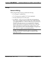
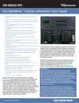
Crestron V24-IMCW-C
Interface Module for V24R-C
and V24RL-C
Installation Guide
This document was prepared and written by the Technical Documentation department at:
Regulatory Compliance
As of the date of manufacture, the V24-IMCW-C has been tested and found to comply with specifications for CE
marking and standards per EMC and Radiocommunications Compliance Labelling.
Federal Communications Commission (FCC) Compliance Statement
This device complies with part 15 of the FCC Rules. Operation is subject to the following conditions:
(1) This device may not cause harmful interference and (2) this device must accept any interference received,
including interference that may cause undesired operation.
CAUTION: Changes or modifications not expressly approved by the manufacturer responsible for compliance
could void the user’s authority to operate the equipment.
NOTE: This equipment has been tested and found to comply with the limits for a Class B digital device,
pursuant to part 15 of the FCC Rules. These limits are designed to provide reasonable protection against harmful
interference in a residential installation. This equipment generates, uses and can radiate radio frequency energy
and, if not installed and used in accordance with the instructions, may cause harmful interference to radio
communications. However, there is no guarantee that interference will not occur in a particular installation. If
this equipment does cause harmful interference to radio or television reception, which can be determined by
turning the equipment off and on, the user is encouraged to try to correct the interference by one or more of the
following measures:
Reorient or relocate the receiving antenna
Increase the separation between the equipment and receiver
Connect the equipment into an outlet on a circuit different from that to which the receiver is connected
Consult the dealer or an experienced radio/TV technician for help
Industry Canada (IC) Compliance Statement
This Class B digital apparatus complies with Canadian ICES-003.
Cet appareil numérique de la classe B est conforme à la norme NMB-003 du Canada.
The specific patents that cover Crestron products are listed at www.crestronpatents.com.
Crestron, the Crestron logo, DigitalMedia, DigitalMedia 8G, DigitalMedia 8G+, DM, DM 8G+ and V-Panel are either
trademarks or registered trademarks of Crestron Electronics, Inc. in the United States and/or other countries. Other
trademarks, registered trademarks and trade names may be used in this document to refer to either the entities claiming
the marks and names or their products. Crestron disclaims any proprietary interest in the marks and names of others.
©2012 Crestron Electronics, Inc.
Crestron V24-IMCW-C
Interface Module for V24R-C and V24RL-C
Contents
Interface Module for V24R-C and V24RL-C: V24-IMCW-C
1
Introduction ............................................................................................................................... 1
Features and Functions ................................................................................................ 2
Specifications .............................................................................................................. 2
Physical Description.................................................................................................... 3
Setup .......................................................................................................................................... 7
Network Wiring........................................................................................................... 7
Supplied Hardware ...................................................................................................... 8
Installation ................................................................................................................... 9
Hardware Hookup ..................................................................................................... 11
Problem Solving ...................................................................................................................... 13
Troubleshooting......................................................................................................... 13
Reference Documents................................................................................................ 13
Further Inquiries ........................................................................................................ 14
Future Updates .......................................................................................................... 14
Return and Warranty Policies .................................................................................................. 15
Merchandise Returns / Repair Service ...................................................................... 15
Crestron Limited Warranty........................................................................................ 15
Installation Guide – DOC. 7175C
Contents • i
Crestron V24-IMCW-C
Interface Module for V24R-C and V24RL-C
Interface Module for V24R-C and
V24RL-C: V24-IMCW-C
Introduction
The V24-IMCW-C is an interface module designed for use with a
V24R-C or V24RL-C V-Panel™ 24” HD Touch Screen Display. It
affords a convenient, pluggable connection for the touch screen,
providing front panel jacks for DigitalMedia 8G+™ (DM 8G+™) and
power. On the rear is a DM 8G+ pass-through jack for connection to a
DM 8G+ transmitter or switcher1. Power is provided to the
V24-IMCW-C by an external power pack2, which may be connected to
either the front or rear panel.
Every V24R-C and V24RL-C touch screen ships with one V24-IMCW-C
included. The V24-IMCW-C may also be purchased separately for use
with a V24R-WALL-C touch screen.
Using the hardware provided, the V24-IMCW-C can be mounted in a
1-gang electrical box, to a flat surface or to a 19-inch rack rail.
1. For DM 8G+ wiring, use Crestron® DM-CBL-8G DigitalMedia 8G™ cable or
generic CAT5e (or better) UTP or STP. Maximum wire length for DM 8G+ is
330 feet (100 meters) between devices. Shielded cable and connectors are
recommended to safeguard against unpredictable environmental electrical noise,
which may impact performance at resolutions above 1080p. All wire and cables
sold separately. Refer to the DigitalMedia™ Design Guide (Doc. 4546) for
complete system design guidelines. It is available from the Crestron Web site
(www.crestron.com/dmresources).
2. Item(s) sold separately or included with touch screen display.
Installation Guide – DOC. 7175C
Interface Module: V24-IMCW-C • 1
Interface Module for V24R-C and V24RL-C
Crestron V24-IMCW-C
Features and Functions
• Provides a wall plate connection for a V-Panel 24” HD Touch
Screen Display
• Mounts in a single-gang electrical box or mud ring
• Includes inserts to match black, white or almond faceplates
• Includes surface mount and rack rail installation options
• Provides pass-through connections for 24VDC power and
DigitalMedia 8G+
Specifications
Specifications for the V24-IMCW-C are listed in the following table.
V24-IMCW-C Specifications
SPECIFICATION
Power Requirements
Power Pack
Environmental
Temperature
Humidity
Enclosure
Construction
Flush Wall Mount
Surface Mount
Rack Mount
DETAILS
3.7 Amps @ 24 VDC
32º to 113º F (0º to 45º C)
10% to 90% RH (non-condensing)
Metal, black finish, includes (3)
metal inserts to allow choice of
black, white or almond front panel
Mounts in a 1-gang electrical box
or in a 1-gang opening in a typical
6 inch (150 mm) deep floor box,
2.5 inch (64 mm) minimum
mounting depth required
decorator style faceplate not
included
Surface mount bracket included
Mountable to a single 19-inch EIA
rack rail
(Continued on following page)
2 • Interface Module: V24-IMCW-C
Installation Guide – DOC. 7175C
Crestron V24-IMCW-C
Interface Module for V24R-C and V24RL-C
V24-IMCW-C Specifications (Continued)
SPECIFICATION
Dimensions
Height
Width
Depth
Weight
DETAILS
4.12 in (105 mm)
1.72 in (44 mm)
1.93 in (49 mm) with surface
mount bracket
1.58 in (40 mm)
5 oz (141 g) with bracket
Physical Description
This section provides information on the connections, controls and
indicators available on the V24-IMCW-C.
V24-IMCW-C Physical View (Front and Rear)
Installation Guide – DOC. 7175C
Interface Module: V24-IMCW-C • 3
Interface Module for V24R-C and V24RL-C
Crestron V24-IMCW-C
V24-IMCW-C Overall Dimensions
1.72 in
(44 mm)
1.60 in
(41 mm)
1
4.12 in
(105 mm)
5
2
6
3
7
2.67 in
(68 mm)
4
0.10 in
(3 mm)
0.06 in
(2 mm)
1.04 in
(27 mm)
1.45 in
(37 mm)
1.38 in
(35 mm)
1.58 in
(40 mm)
4 • Interface Module: V24-IMCW-C
8
6.00 in
(153 mm)
Installation Guide – DOC. 7175C
Crestron V24-IMCW-C
Interface Module for V24R-C and V24RL-C
Connectors, Controls & Indicators
#
CONNECTORS1,
CONTROLS &
INDICATORS
DESCRIPTION
1
TO PANEL
DM
(1) 8-pin RJ-45 female, shielded;
Connects to a V24R-C touch screen
via a V-CBL-SC cable2
2
TO PANEL
G, 24
G
24
PIN
COLOR
1
2
3
4
5
6
7
8
White/Orange
Orange
White/Green
Blue
White/Blue
Green
White/Brown
Brown
(1) 2-pin 5 mm detachable terminal
block;
Connects to a V24R-C touch screen
via a V-CBL-SC cable2
3
PWR IN
24VDC 3.7A
(1) 2.1 x 5.5 mm DC power
connector;
24 Volt DC power input from power
pack2
4
PWR LED
(1) Green LED, indicates DC power
supplied from power pack
(Continued on following page)
Installation Guide – DOC. 7175C
Interface Module: V24-IMCW-C • 5
Interface Module for V24R-C and V24RL-C
Crestron V24-IMCW-C
Connectors, Controls, & Indicators (Continued)
#
CONNECTORS1,
CONTROLS &
INDICATORS
5
DM
6
DESCRIPTION
(1) 8-pin RJ-45 female, shielded;
DM 8G+ input;
Connects to DM 8G+ output of a
DM® transmitter or switcher via
CAT5e or Crestron DM-CBL-8G
cable2, 3
PWR IN
24, G
24
G
7
PWR IN
24VDC 3.7A
8
Ground
PIN
COLOR
1
2
3
4
5
6
7
8
White/Orange
Orange
White/Green
Blue
White/Blue
Green
White/Brown
Brown
(1) 2-pin 5 mm detachable terminal
block;
24 Volt DC power input from power
pack2
(1) 2.1 x 5.5 mm DC power
connector;
24 Volt DC power input from power
pack2
(1) Flying lead, ground wire
1. An interface connector for the PWR IN 24, G port is provided with the unit.
2. Item(s) sold separately or included with touch screen display.
3. For DM 8G+ wiring, use Crestron DM-CBL-8G DigitalMedia 8G cable or
generic CAT5e (or better) UTP or STP. Maximum wire length for DM 8G+ is
330 feet (100 meters) between devices. Shielded cable and connectors are
recommended to safeguard against unpredictable environmental electrical noise,
which may impact performance at resolutions above 1080p. All wire and cables
sold separately. Refer to the DigitalMedia Design Guide (Doc. 4546) for complete
system design guidelines.
6 • Interface Module: V24-IMCW-C
Installation Guide – DOC. 7175C
Crestron V24-IMCW-C
Interface Module for V24R-C and V24RL-C
Setup
Network Wiring
When wiring the DM® network, consider the following:
• Use Crestron® Certified Wire.
• Use Crestron power supplies for Crestron equipment.
• Provide sufficient power to the system.
• For DM 8G+ wiring, use Crestron DM-CBL-8G DigitalMedia
8G™ cable or generic CAT5e (or better) UTP or STP. Maximum
wire length for DM 8G+ is 330 feet (100 meters) between devices.
Shielded cable and connectors are recommended to safeguard
against unpredictable environmental electrical noise, which may
impact performance at resolutions above 1080p. All wire and
cables sold separately. Refer to the DigitalMedia™ Design Guide
(Doc. 4546) for complete system design guidelines.
NOTE: For optimum performance and ESD (electrostatic
discharge) protection, Crestron strongly recommends using
DM-CBL-8G cable.
Installation Guide – DOC. 7175C
Interface Module: V24-IMCW-C • 7
Interface Module for V24R-C and V24RL-C
Crestron V24-IMCW-C
Supplied Hardware
The hardware supplied with the V24-IMCW-C is listed in the following
table.
Supplied Hardware for the V24-IMCW-C
DESCRIPTION
PART
NUMBER
QTY
Assy, Insert, Black
Assy, Insert, White
Assy, Insert, Almond
Metal, Bracket, 16 GA CRS
Conn, Plug, 2-pin, SKT, Single Row
Plastic, Hole Plug, Ferrule Dust Cap
Screw, #06-32 x 3/4”, Combo HD
Screw, #06-32 x 3/16”, Pan, Phil
4513890
4513789
4513891
2016054
2003582
2031467
2009211
2007203
1
1
1
1
1
1
2
2
8 • Interface Module: V24-IMCW-C
Installation Guide – DOC. 7175C
Crestron V24-IMCW-C
Interface Module for V24R-C and V24RL-C
Installation
The V24-IMCW-C can be installed in either a 1-gang box, rack mounted
or mounted to any flat surface using the provided surface mount bracket.
Installing in
1-Gang Box
To install the V24-IMCW-C in a 1-gang box, ensure the unit is
mounted into the electrical box as shown in the following illustration.
V24-IMCW-C in 1-Gang Box (Exploded View)
1-Gang Electrical Box
(Not Supplied)
V24-IMCW-C
(4513883)
Screws (2) #6-32 x 3/4"
(2009211)
Wall Plate with Hardware
(Not Included)
Assy, Insert, Black
(4513890)
or
Assy, Insert, White
(4513789)
or
Assy, Insert, Almond
(4513891)
Installation Guide – DOC. 7175C
Interface Module: V24-IMCW-C • 9
Interface Module for V24R-C and V24RL-C
Rack
Mounting
Crestron V24-IMCW-C
The V24-IMCW-C can be mounted in a rack with other equipment
using two of the four mounting holes on the corners of the interface
module, as shown in the following illustration.
V24-IMCW-C Rack Mount (Exploded View)
Rack Rail
V24-IMCW-C
(4513883)
Assy, Insert, Black
(4513890)
or
Assy, Insert, White
(4513789)
or
Assy, Insert, Almond
(4513891)
Rack Mount Screws
(Not Included)
WARNING: To prevent bodily injury when mounting or servicing this
unit in a rack, observe the following guidelines:
• When mounting this unit in a partially filled rack, load the rack
from the bottom to the top with the heaviest component at the
bottom of the rack.
• If the rack is provided with stabilizing devices, install the
stabilizers before mounting or servicing the unit in the rack.
10 • Interface Module: V24-IMCW-C
Installation Guide – DOC. 7175C
Crestron V24-IMCW-C
Installing on
a Level
Surface
Interface Module for V24R-C and V24RL-C
To prepare the V24-IMCW-C to be mounted onto a level surface,
ensure the unit is attached to the surface mount bracket, as shown in
the following illustration.
V24-IMCW-C Bracket Mount (Exploded View)
V24-IMCW-C
(4513883)
Mounting Bracket
(2016054)
Screws (2) #6-32 x 3/16"
(2007203)
Assy, Insert, Black
(4513890)
or
Assy, Insert, White
(4513789)
or
Assy, Insert, Almond
(4513891)
Hardware Hookup
Make the necessary connections as called out in the illustrations below.
Refer to “Network Wiring” on page 7 before attaching the 4-position
terminal block connector. Apply power after all connections have been
made.
When making connections to the V24-IMCW-C, use Crestron power
supplies for Crestron equipment.
Installation Guide – DOC. 7175C
Interface Module: V24-IMCW-C • 11
Interface Module for V24R-C and V24RL-C
Crestron V24-IMCW-C
Hardware Connections for the V24-IMCW-C (Front)
TO PANEL – DM:
To V24R-C
Touch Screen
TO PANEL – G, 24:
To V24R-C
Touch Screen
PWR IN – 24VDC 3.7A:
From DC Power Pack
*
A ferrule dust cap (2031467) is provided to cover the front panel DC power jack
when not in use.
Hardware Connections for the V24-IMCW-C (Rear)
DM:
From DM Transmitter
or Switcher
PWR IN – 24, G:
From DC Power Pack
PWR IN – 24VDC 3.7A:
From DC Power Pack
CAUTION: The V24-IMCW-C can be powered via the 24 G 2-pin
connection on the rear of the unit or the 24VDC 3.7A jacks on either the
front or the rear of the unit. To avoid possible damage to the unit, use
only one of these connectors.
NOTE: Ensure the unit is properly grounded by connecting the chassis
ground lug to an earth ground (building steel).
12 • Interface Module: V24-IMCW-C
Installation Guide – DOC. 7175C
Crestron V24-IMCW-C
Interface Module for V24R-C and V24RL-C
Problem Solving
Troubleshooting
The following table provides corrective action for possible trouble
situations. If further assistance is required, please contact a Crestron
customer service representative.
V24-IMCW-C Troubleshooting
TROUBLE
POSSIBLE
CAUSE(S)
CORRECTIVE
ACTION
Device does not
function.
Device is not
receiving
sufficient power.
PWR LED does
not illuminate.
Device is not
receiving
sufficient power.
Loss of
functionality
due to
electrostatic
discharge.
Improper
grounding.
Use a Crestron
approved power
source and verify
connections.
Use a Crestron
approved power
source and verify
connections.
Check that all ground
connections have
been made properly.
Reference Documents
The latest version of all documents mentioned within the guide can be
obtained from the Crestron Web site
(http://www.crestron.com/dmresources).
List of Related Reference Documents
DOCUMENT TITLE
DigitalMedia Design Guide
Installation Guide – DOC. 7175C
Interface Module: V24-IMCW-C • 13
Interface Module for V24R-C and V24RL-C
Crestron V24-IMCW-C
Further Inquiries
To locate specific information or resolve questions after reviewing this
guide, contact Crestron's True Blue Support at 1-888-CRESTRON
[1-888-273-7876] or refer to the listing of Crestron worldwide offices on
the Crestron Web site (www.crestron.com/offices) for assistance within a
particular geographic region.
To post a question about Crestron products, log onto the Online Help
section of the Crestron Web site (www.crestron.com/onlinehelp).
First-time users must establish a user account to fully benefit from all
available features.
Future Updates
As Crestron improves functions, adds new features and extends the
capabilities of the V24-IMCW-C, additional information may be made
available as manual updates. These updates are solely electronic and
serve as intermediary supplements prior to the release of a complete
technical documentation revision.
Check the Crestron Web site periodically for manual update availability
and its relevance. Updates are identified as an “Addendum” in the
Download column.
14 • Interface Module: V24-IMCW-C
Installation Guide – DOC. 7175C
Crestron V24-IMCW-C
Interface Module for V24R-C and V24RL-C
Return and Warranty Policies
Merchandise Returns / Repair Service
1.
No merchandise may be returned for credit, exchange or service without prior authorization
from Crestron. To obtain warranty service for Crestron products, contact an authorized
Crestron dealer. Only authorized Crestron dealers may contact the factory and request an
RMA (Return Merchandise Authorization) number. Enclose a note specifying the nature of
the problem, name and phone number of contact person, RMA number and return address.
2.
Products may be returned for credit, exchange or service with a Crestron Return Merchandise
Authorization (RMA) number. Authorized returns must be shipped freight prepaid to
Crestron, 6 Volvo Drive, Rockleigh, N.J. or its authorized subsidiaries, with RMA number
clearly marked on the outside of all cartons. Shipments arriving freight collect or without an
RMA number shall be subject to refusal. Crestron reserves the right in its sole and absolute
discretion to charge a 15% restocking fee plus shipping costs on any products returned with
an RMA.
3.
Return freight charges following repair of items under warranty shall be paid by Crestron,
shipping by standard ground carrier. In the event repairs are found to be non-warranty, return
freight costs shall be paid by the purchaser.
Crestron Limited Warranty
Crestron Electronics, Inc. warrants its products to be free from manufacturing defects in materials and
workmanship under normal use for a period of three (3) years from the date of purchase from Crestron,
with the following exceptions: disk drives and any other moving or rotating mechanical parts, pan/tilt heads
and power supplies are covered for a period of one (1) year; touch screen display and overlay components
are covered for 90 days; batteries and incandescent lamps are not covered.
This warranty extends to products purchased directly from Crestron or an authorized Crestron dealer.
Purchasers should inquire of the dealer regarding the nature and extent of the dealer's warranty, if any.
Crestron shall not be liable to honor the terms of this warranty if the product has been used in any
application other than that for which it was intended or if it has been subjected to misuse, accidental
damage, modification or improper installation procedures. Furthermore, this warranty does not cover any
product that has had the serial number altered, defaced or removed.
This warranty shall be the sole and exclusive remedy to the original purchaser. In no event shall Crestron
be liable for incidental or consequential damages of any kind (property or economic damages inclusive)
arising from the sale or use of this equipment. Crestron is not liable for any claim made by a third party or
made by the purchaser for a third party.
Crestron shall, at its option, repair or replace any product found defective, without charge for parts or labor.
Repaired or replaced equipment and parts supplied under this warranty shall be covered only by the
unexpired portion of the warranty.
Except as expressly set forth in this warranty, Crestron makes no other warranties, expressed or implied,
nor authorizes any other party to offer any warranty, including any implied warranties of merchantability or
fitness for a particular purpose. Any implied warranties that may be imposed by law are limited to the terms
of this limited warranty. This warranty statement supersedes all previous warranties.
Installation Guide – DOC. 7175C
Interface Module: V24-IMCW-C • 15
Crestron Electronics, Inc.
15 Volvo Drive Rockleigh, NJ 07647
Tel: 888.CRESTRON
Fax: 201.767.7576
www.crestron.com
Installation Guide – DOC. 7175C
(2030554)
09.12
Specifications subject to
change without notice.