1
CAT.E813- B
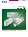
Multistage Ejector
Series ZL
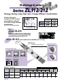
New Models! ZL212 large flow rate type and ZL112 with valve.
Multistage Ejector
Series ZL112/212
Energy saving, large flow rate, 3 stage diffuser construction
Vacuum pressure
ance
rform
e pe
1 stag
Suction flow rate
increased 250% and air
consumption reduced
20% with 3 stage diffuser
construction
Q1
Maximum
suction flow rate Air consumption
l /min (ANR)
l /min (ANR)
Q1
Q2
Q3
Q2
2 stage
perform
ance
3 stage
(Versus ø1.3, one stage model)
performance
250 % suction flow
rate increase
NEW
Series
ZL112
Q3
ZL212
100
200
63
126
Suction
flow rate
ZL212
Diffusers stacked and integrated
Compact size and large flow rate
(twice the flow rate of the ZL112)
Series ZL112
valve option now available (ZL112 only)
Release valve
Release flow rate
adjustment needle
Supply valve
Exhaust port options
One-touch fitting feature
Built-in silencer
Makes piping work easy (ZL112 only)
Vacuum pressure sensor
With digital vacuum pressure switch
SMC PRESSURE SWITCH
SMC PRESSURE SWITCH
SMC PRESSURE SWITCH
RESET
RESET
SET
SET
Port exhaust
UNIT
RESET SET
LCD display/ZSE4
LCD display with
back light/ZSE4B
With vacuum
adapter
With vacuum
pressure gauge
LED display/ZSE4E
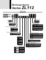
Series variations
Series
Vacuum pressure sensor options
Air
Maximum
suction flow rate consumption
l/min (ANR)
l/min (ANR)
ZL112
100
63
ZL212
200
126
Features
Exhaust port
Built-in
silencer
Port
exhaust
With valve
With
With
supply valve/
release valve supply valve
Digital vacuum pressure switch
ZSE4E
ZSE4B
ZSE4
Vacuum
pressure
gauge
Vacuum
adapter
Multistage Ejector
Series
ZL112
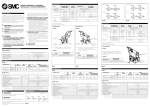
How to Order
Without valve
With valve
ZL1 12
ZL1 12
K1 5 M Z
E 25
Lead wire length
Nozzle diameter
ø1.2mm
12
Nil
L
Digital vacuum pressure
switch specifications
Exhaust specifications
Nil
P
Built-in silencer
Port exhaust
For E (ZSE4) EB (ZSE4B)
25 NPN output Lead wire length 0.5 (2.9)m
26 Analog output Lead wire length 0.5 (2.9)m
65 PNP output Lead wire length 0.5 (2.9)m
For EE (ZSE4E)
27 NPN output Lead wire length 0.5 (2.9)m
26 Analog output Lead wire length 0.5 (2.9)m
67 PNP output Lead wire length 0.5 (2.9)m
Exhaust port thread specification
(port exhaust only)
Nil
F
N
T
Rc1/2
G1/2
1/2-14NPT
1/2-14NPTF
∗ Not required for nil, vacuum adapter (GN) and
vacuum pressure gauge (G).
Supply valve/Release valve combination
K1
K2
Vacuum pressure sensor
With supply and release valves
With supply valve
Nil
GN
G
E
EB
EE
Rated voltage
DC specifications
5
6
V
S
R
24VDC
12VDC
6VDC
5VDC
3VDC
1
2
3
4
100VAC
200VAC
110VAC [115V]
220VAC [230V]
Electrical entry
Lead wire length 0.3m
Lead wire length 0.6m
Lead wire length 0.3m
L type plug
Without lead wires
connector
Without connector
Lead wire length 0.3m
M type plug
Without lead wires
connector
Without connector
Grommet
None
Vacuum adapter Rc1/8
With vacuum pressure gauge
With digital vacuum pressure switch ZSE4
With digital vacuum pressure switch ZSE4B
With digital vacuum pressure switch ZSE4E
Manual override
Nil
D
AC specifications (50/60Hz)
G
H
L
LN
LO
M
MN
MO
0.5m
2.9m
Non-locking push type
Slotted locking type
Light/Surge voltage suppressor
Nil
S
Z
U
Without light/surge voltage suppressor
With surge voltage suppressor
With light/surge voltage suppressor
With light/surge voltage suppressor (non-polar type)
Note 1) Type U is 24 or 12VDC only.
Note 2) Since surge voltage is prevented by a rectifier in
the case of AC, there is no "S" type.
1
Series
ZL
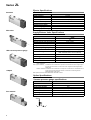
Ejector Specifications
Standard
ZL112
Model
Nozzle diameter
Maximum suction flow rate
Air consumption
Maximum vacuum pressure
Maximum operating pressure
Supply pressure range
Standard supply pressure
Operating temperature range
With valve
ø1.2mm
100l/min (ANR)
63l/min (ANR)
–84kPa
0.7MPa
0.2 to 0.5MPa
0.4MPa
5 to 50°C
Supply/Release Valve Specifications
SYJ514-
Part Number
N.C.
Type of valve actuation
Air
Fluid
0.2 to 0.5MPa
Operating pressure range Internal pilot type
5 to 50°C
Ambient and fluid temperature
Response time (for 0.5MPa) Note 1)
25ms or less
5Hz
Maximum operating frequency
With vacuum pressure gauge
Manual operation
Non-locking push type, Slotted locking type
Pilot exhaust type
Pilot valve individual exhaust type,
Main valve/Pilot valve common exhaust
Lubrication
Not required
Mounting position
Unrestricted
Impact/Vibration resistance Note 2)
150/30m/s²
Enclosure
Dust proof
Note 1) Based on JIS B8374-1981 dynamic performance test. (coil temperature 20°C, at rated voltage, without surge
voltage suppressor)
Note 2) Impact resistance:
Adapter
No malfunction when tested with a drop tester in the axial direction and at a right angle to
the main valve and armature, one time each in both energized and deenergized states.
(initial value)
Vibration resistance: No malfunction when tested with one sweep of 8.3 to 2000Hz in the axial direction and at
a right angle to the main valve and armature, one time each in both energized and
deenergized states. (initial value)
Note 3) Refer to CAT.E143-B "SYJ300/500/700" for details on valves.
Option Specifications
Vacuum pressure gauge specifications
Port exhaust
Part number
Fluid
Pressure range
Scale range (angular)
Accuracy
Class
Operating temperature range
Material
Symbol
Standard
P
2
V
GZ30S
Air
–100 to 100kPa
230°
± 3% F.S. (full span)
Class 3
0 to 50°C
Housing: Polycarbonate/ABS resin
Multistage Ejector
Series
ZL
Option Specifications
With digital vacuum
pressure switch
(ZSE4)
Digital vacuum pressure switch specifications
Part number
Display
Pressure setting range
Maximum operating pressure
ZSE4-00--X105 ZSE4B-00--X105 ZSE4E-00--X105
LCD
LCD with back light
LED
–101 to 10KPa {–760 to 75mmHg}
200KPa
Operation indicator light
(lights up when ON)
Response frequency
Hysteresis
OUT1: Green
OUT2: Red
Green
200Hz (5ms)
Hysteresis mode
Window comparator mode
Variable (3 digits or more)
Fixed (3 digits)
Fluid
Temperature characteristics
Variable (can be set from 0)
Air, Non-corrosive gas
±3% F.S. or less
±1% F.S. or less
Repeatability
12 to 24VDC (ripple ±10% or less )
Operating voltage
Current consumption
25mA or less
Pressure indication
45mA or less
–26, –27: 50mA or less
–67: 60mA or less
3 1/2 digits (character height 8mm)
Self diagnostic function
Operating temperature range
Noise resistance
(Over current Note 1)), Over pressure, Data error, Presence of pressure at 0 clear
0 to 50°C (with no condensation)
500Vp-p, Pulse width: 1µS, Start up: 1nS
Withstand voltage
Between external terminal batch and case: 1000VAC 50/60Hz for 1 min.
Insulation resistance
Between external terminal batch and case: 2MΩ (at 500VDC)
Vibration resistance
2hrs. each in X, Y, Z directions at smaller of 10 to 500Hz
with amplitude 1.5mm, or acceleration 10G
100G in X, Y, Z directions, 3 times each
Impact resistance
Note 1) Not available on analog output type.
∗ Refer to CAT.E824-A "Pressure Switch" for details on switches.
Output specifications
ZSE4
ZSE4B
ZSE4E
–25 (L)
–26 (L)
–67 (L)
–26 (L)
–27 (L)
–67 (L)
1 output NPN open collector 30V, 80mA or less
Analog output (1 to 5V)
1 output PNP open collector 80mA or less
Analog output (1 to 5V)
2 outputs NPN open collector 30V, 80mA or less
2 outputs PNP open collector 80mA or less
∗ Refer to CAT.E824-A "Pressure Switch" for details on switches.
3
Series
ZL
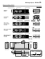
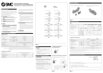
Construction
Without valve
With valve
Replacement parts
Parts list
No.
1
Description
Suction cover
2
Front cover
3
End cover
4
Body
5
Vacuum sensor unit
6
Nozzle
7
Diffuser
8
4
Part No.
Note
Without valve
No.
Description
Material
9
Sound absorbing material B
PVF
10
Sound absorbing material A
PVF
11
Suction filter
PE
Part No.
ZL112-SP01
(set no. for 9, 10 &11)
∗ When ordering a vacuum pressure gauge or a digital vacuum pressure switch
separately, use the part numbers shown in the option specifications on page 3.
Detent plug
P397110
Other than vacuum switch
Lead wire cover
P397176
Vacuum switch specifications
12
Front cover B
With valve
13
Valve plate
With valve
14
Needle
15
Supply valve (N.C.)
SYJ514
With valve
16
Release valve (N.C.)
SYJ514
With valve
With valve
Multistage Ejector
Series
ZL
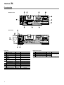
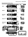
Dimensions/Series ZL112 (without Valve)
50
2-ø5.4
Mounting hole
117
Exhaust with silencer
Scale: 40%
Label
P
20
Standard
V
ZL112
166
4.5
56
Exhaust port
Rc1/2
35
P
Port exhaust
V
ZL112P
14
Exhaust with silencer
Vacuum pressure gauge
2-ø5.4
Mounting hole
P
With vacuum
pressure gauge
V
ZL112-G
Exhaust with silencer
Vacuum adapter Rc1/8
With vacuum adapter
2-ø5.4
Mounting hole
7
P
V
ZL112-GN
61
2-ø5.4
Mounting hole
Exhaust with silencer
Vacuum pressure switch
P
V
SET
With digital vacuum
pressure switch
RESET
ZL112-E
Approx. 500 (L: Approx. 2900)
Pressure supply port
One-touch fitting ø6
Section A
Vacuum port
One-touch fitting ø12
2-ø5.4
Mounting hole
Label
MULTISTAGE
59.5
30
8.5
56
166
175
36
4.5
Section A
with digital vacuum pressure switch
ZL112-EB (ZSE4B)
ZL112-EE (ZSE4E)
(1.6)
28
ZL112-E
(ZSE4)
4-M4 x 0.7
Thread depth 8
(mounting hole)
85
(2)
59
EJECTOR
59
5
ZL
Series
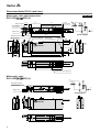
Dimensions/Series ZL112 (with Valve)
With supply valve and release valve
Scale: 40%
ZL112-K1L-E25 (L)
13.5
50
Manual override
P
2-ø5.4
Mounting hole
117
Vacuum pressure switch Exhaust with silencer
Release valve
P
20
V
RESET SET
V
Supply valve
19
166
Release flow rate adjustment needle
Manual override
Pressure supply port
One-touch fitting ø6
Circuit diagram
4.5
Vacuum port
One-touch fitting ø12
2-ø5.4
Mounting hole
500
(L: 2900)
-+
Label
-+
66.5
MULTISTAGE
166
17
4.5
216
28
36
8.5
30
35.7
59.5
EJECTOR
59
85
4-M4 x 0.7
Thread depth 8 (mounting hole)
With supply valve
ZL112-K2L-E25 (L)
P
Blank plate assembly
(SYJ500-10-2A)
P
V
RESETSET
V
Supply valve
Circuit diagram
-+
MULTISTAGE
EJECTOR
6
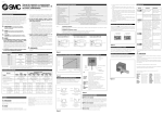
Multistage Ejector
ZL212
Series
Standard
How to Order
ZL2 12
Nozzle diameter
ø1.2mm
12
Lead wire length
Nil
L
With vacuum pressure gauge
0.5m
2.9m
Exhaust specifications
Nil
P
Built-in silencer
Port exhaust
Digital vacuum pressure switch
specifications
Vacuum pressure sensor
Nil
GN
G
E
EB
EE
With digital vacuum pressure switch
None
Adaptor Rc1/8
With vacuum pressure gauge
With digital vacuum pressure switch ZSE4
With digital vacuum pressure switch ZSE4B
With digital vacuum pressure switch ZSE4E
For E (ZSE4) EB (ZSE4B)
25 NPN output Lead wire length 0.6 (3.0)m
26 Analog output Lead wire length 0.6 (3.0)m
65 PNP output Lead wire length 0.6 (3.0)m
For EE (ZSE4E)
27 NPN output Lead wire length 0.6 (3.0)m
26 Analog output Lead wire length 0.6 (3.0)m
67 PNP output Lead wire length 0.6 (3.0)m
∗ Not required for nil, vacuum adapter (GN) and
vacuum pressure gauge (G).
Ejector Specifications
Model
Nozzle diameter
Maximum suction flow rate
Air consumption
Maximum vacuum pressure
Maximum operating pressure
Supply pressure range
Standard supply pressure
Operating temperature range
With adaptor
ZL212
ø1.2mm x 2
200l/min (ANR)
126l /min (ANR)
– 84kPa
0.7MPa
0.2 to 0.5MPa
0.4MPa
5 to 50°C
∗ Refer to pages 2 and 3 for vacuum pressure gauge and digital vacuum pressure switch specifications.
Port exhaust
Symbol
Standard
P
V
7
Series
ZL
Construction
Replacement parts
Parts list
No.
Suction cover
2
Front cover A
3
End plate
4
Body
5
Vacuum sensor unit
6
Nozzle
7
Diffuser
8
8
Description
1
Part No.
Note
No.
Description
Material
Part No.
9
Sound absorbing material A
PVF
P397114
10
Sound absorbing material
PVF
P397230
∗ When ordering a vacuum pressure gauge or a digital vacuum pressure switch
separately, use the part numbers shown in the option specifications on page 3.
Detent plug
P397110
Other than vacuum switch
Lead wire cover
P397176
Vacuum switch specifications
Multistage Ejector
Series
ZL
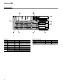
Dimensions/Series ZL212
Vacuum port Rc3/4
Pressure supply port Rc1/8
Scale: 40%
Exhaust with silencer
76
P
40
Standard
ZL212
V
54
125
Label
188
61
P
Port exhaust
V
ZL212P
Exhaust port Rc1
Vacuum pressure gauge
Exhaust with silencer
25
P
With vacuum
pressure gauge
V
ZL212-G
Vacuum adapter Rc1/8
Exhaust with silencer
7
P
With vacuum adapter
V
ZL212-GN
Vacuum pressure switch
With digital vacuum
pressure switch
Exhaust with silencer
P
V
RESET SET
ZL212-E
Approx. 500
(L: approx. 2900)
Section A
2-ø4.4
Mounting hole
MULTISTAGE
8
52
76
EJECTOR
178.5
4.5
Section A
with digital vacuum pressure switch
ZL212-EB (ZSE4B)
ZL212-EE (ZSE4E)
(1.6)
27
ZL212-E
(ZSE4)
(2)
5
(40)
4-M5 x 0.8
Thread depth 6
(mounting hole)
73
87
9
Series ZL
Safety Instructions
These safety instructions are intended to prevent a hazardous situation and/or
equipment damage. These instructions indicate the level of potential hazard by labels of
"Caution", "Warning" or "Danger". To ensure safety, be sure to observe ISO 4414 Note 1),
JIS B 8370 Note 2) and other safety practices.
Caution : Operator error could result in injury or equipment damage.
Warning : Operator error could result in serious injury or loss of life.
Danger :
In extreme conditions, there is a possible result of serious injury or loss of life.
Note 1) ISO 4414 : Pneumatic fluid power -- Recommendations for the application of equipment to transmission and control
systems.
Note 2) JIS B 8370 : General Rules for Pneumatic Systems
Warning
1. The compatibility of pneumatic equipment is the responsibility of the person
who designs the pneumatic system or decides its specifications.
Since the products specified here are used in various operating conditions, their compatibility for the
specific pneumatic system must be based on specifications or after analysis and/or tests to meet your
specific requirements.
2. Only trained personnel should operate pneumatically operated machinery
and equipment.
Compressed air can be dangerous if an operator is unfamiliar with it. Assembly, handling or repair of
pneumatic systems should be performed by trained and experienced operators.
3. Do not service machinery/equipment or attempt to remove components until
safety is confirmed.
1. Inspection and maintenance of machinery/equipment should only be performed after confirmation of
safe locked-out control positions.
2. When equipment is to be removed, confirm the safety process as mentioned above. Cut the supply
pressure for this equipment and exhaust all residual compressed air in the system.
3. Before machinery/equipment is restarted, take measures to prevent shooting-out of cylinder piston rod,
etc. (Bleed air into the system gradually to create back pressure.)
4. Contact SMC if the product is to be used in any of the following conditions:
1. Conditions and environments beyond the given specifications, or if product is used outdoors.
2. Installation on equipment in conjunction with atomic energy, railway, air navigation, vehicles, medical
equipment, food and beverages, recreation equipment, emergency stop circuits, press applications, or
safety equipment.
3. An application which has the possibility of having negative effects on people, property, or animals,
requiring special safety analysis.
10
Series ZL
Vacuum Equipment Precautions 1
Be sure to read before handling.
Selection
Air Supply
Warning
Warning
1. Confirm the specifications.
The products appearing in this catalog are designed for use only
in compressed air systems (including vacuum).
Do not use outside the specified ranges of pressure, temperature,
etc., as this may cause damage or faulty operation. (Refer to
specifications.)
Consult with SMC if fluids other than compressed air (including
vacuum) are to be used.
Mounting
Warning
1. Read the instruction manual carefully.
The product should be mounted and operated with a good understanding of its contents. Also, keep the manual where it can be
easily referred to at any time.
2. Ensure space for maintenance.
Ensure the necessary space for maintenance activities.
3. Be sure to tighten screws with the proper
torque.
4. Types of air
Do not use compressed air containing chemicals, synthetic oil
which includes organic solvents, salt, corrosive gases, etc., as this
may cause damage or malfunction.
Operating Environment
Warning
1. Do not operate in locations having an atmosphere of corrosive gases, chemicals, sea
water, fresh water or water vapor, or where
there will be contact with the same.
2. In locations which receive direct sunlight, the
sunlight should be blocked .
3. Do not operate in locations where vibration
or impact occurs.
4. Do not operate in locations near heat sources
where radiated heat will be received.
When mounting, tighten screws with the recommended torque.
Piping
Caution
1. Preparation before piping
Before piping is connected, it should be thoroughly blown out with
air (flushing) or washed to remove chips, cutting oil and other
debris from inside the pipe.
2. Wrapping of pipe tape
When screwing together pipes and fittings, etc., be certain that
chips from the pipe threads and sealing material do not get inside
the piping.
Further, when pipe tape is used, leave 1.5 to 2 thread ridges
exposed at the end of the threads.
Air Supply
Warning
1. Types of fluid
This product is designed for use with pressurized air. Consult with
SMC if a different fluid is to be used.
Consult SMC regarding products to be used with general purpose
fluids, to confirm which fluids may be used.
2. When there is a large amount of drainage
Pressurized air containing a large amount of drainage can cause
the malfunction of pneumatic equipment. An air dryer or Drain
Catch should be installed upstream from filters.
3. Drain management
If the air filter drains are not flushed regularly, the drainage will
flow downstream from the drains and this may lead to the malfunction of pneumatic equipment.
In cases where the management of drain flushing will be difficult,
the use of filters with automatic drains is recommended.
For details on the qualities of compressed air, refer to SMC's "Air
Cleaning Equipment” catalog.
Maintenance
Warning
1. Maintenance should be performed in accordance with procedures in the instruction
manual.
Improper handling may cause damage or malfunction of equipment or machinery.
2. Maintenance work
Improper handling of compressed air is dangerous. Therefore, in
addition to observing the product specifications, replacement of
elements and other maintenance activities should be performed
by personnel having sufficient knowledge and experience pertaining to pneumatic equipment.
3. Drain flushing
Drainage should be flushed from air filter and other drains on a
regular basis. (Refer to specifications.)
4. Pre-maintenance inspection
When removing this product, turn off the electric power and be
certain to shut off the supply pressure and exhaust the compressed air in the system. Proceed only after confirming that all
pressure has been released to the atmosphere.
5. Post maintenance inspection
After installation, repair or reconstruction, reconnect pressurized
air and electric power, and then perform inspections for proper
operation and air leakage. If the sound of air leakage can be
heard, or if the equipment does not operate properly, stop operation and confirm that it is mounted correctly.
6. Disassembly and alteration prohibited.
Do not disassemble the unit or make any alterations to it.
11
Series ZL
Vacuum Equipment Precautions 2
Be sure to read before handling.
Design & Selection
Warning
1. Create a safe design, which addresses the
possibility of accidents resulting from a drop
in vacuum pressure due to power failure or
trouble with the air supply, etc.
If vacuum pressure drops and there is a loss of vacuum pad adsorption force, work pieces being carried may fall, causing a danger of
human injury and/or damage to machinery. Safety measures should
be implemented, such as the installation of drop prevention guides.
2. Use vacuum specifications for vacuum
switching valves and vacuum breakers.
If valves which do not meet vacuum specifications are installed in
vacuum piping, vacuum leakage will occur. Be certain to use vacuum specification valves.
3. Select ejectors which have a suitable suction
flow rate.
<When there is a vacuum leak from the work piece or the piping>
If the ejector's suction flow rate is too low, this will cause poor adsorption.
<When piping is long or of large diameter>
The adsorption response time will increase due to the increased volume of the piping.
Select ejectors with a suitable suction flow rate by referring to their
technical data.
4. If the suction flow rate is too high, setting of
vacuum switches will become difficult.
In the case of adsorption on a small work piece of only a few millimeters, if an ejector is selected which has a high suction flow rate,
the pressure difference when adsorbing and releasing the work
piece is small. Since setting of the vacuum switch may become difficult, an appropriate ejector should be selected.
5. When two or more pads are piped to one ejector, if one pad releases its work piece, the
other pads will also release.
When one pad is removed from its work piece, there is a drop in vacuum pressure which causes the other pads to release their work
pieces also.
6. Use piping with an adequate effective sectional area.
Select piping for the vacuum side which has an adequate effective
sectional area, so that the ejector's maximum suction flow rate can
be accommodated by the piping.
Also, make sure that there are no unnecessary restrictions or leaks,
etc., along the course of the piping.
The piping on the air supply side must be designed so that it corresponds to each ejector's air consumption. The effective sectional
area of tubing, fittings and valves, etc., should be sufficiently large,
and the pressure drop reaching the ejector should be kept to a minimum.
Further, design of the air supply should be performed while taking
into consideration the ejector's maximum air consumption and the air
consumption of other pneumatic circuits.
Caution
1. For information on related items, such as
directional control equipment and drive equipment, refer to the caution sections in each
respective catalog.
12
Mounting
Warning
1. Do not obstruct the exhaust port of the ejector.
If the exhaust port is obstructed when mounted, a vacuum will not be
generated.
Piping
Caution
1. Avoid disorganized piping.
Piping which is direct and of the shortest possible length should
be used for both the vacuum and supply sides, and disorganized
piping should be avoided. Unnecessary length increases the piping volume, and this increases the response time.
2. Use piping having a large effective sectional area on the exhaust side of the ejector.
If the exhaust piping is restrictive, there will be a decline in the
ejector's performance.
3. Make sure that there are no crushed areas in
the piping due to damage or bending.
Operating Environment
Warning
1. Do not operate in locations having an atmosphere of corrosive gases, chemicals, sea
water, water or steam, or where there will be
contact with the same.
2. Do not operate in locations having an explosive atmosphere.
3. Do not operate in locations where vibration
or impact occurs.
Confirm the specifications for each series.
4. In locations which receive direct sunlight,
provide a protective cover, etc.
5. In locations near heat sources, block off any
radiated heat.
6. In locations where there is contact with
water, oil or welding spatter, etc., implement
suitable protective measures.
7. In cases where the vacuum unit is surrounded by other equipment or it is energized for
an extended time etc., implement measures
to radiate excess heat so that temperatures
remain within the range of specifications.
Maintenance
Warning
1. Clean suction filters and silencers on a regular basis.
The performance of ejectors will deteriorate due to clogging in filters and silencers. Large capacity filters should be used, especially in dusty locations.
Series ZL
Electronic Pressure Switch Precautions 1
Be sure to read before handling.
Design & Selection
Wiring
Warning
Warning
1. Use with the specified voltage.
Use with voltage outside of the specifications can cause malfunction or switch damage, as well as electrocution and fire hazard,
etc.
2. Never use a load which exceeds the maximum load capacity.
This may damage a switch or reduce its service life.
3. Do not use a load that generates surge voltage.
Although surge protection is provided at the output side of a
switch, damage may still occur if the surge is applied repeatedly.
When a load, such as a relay or solenoid, which generates surge
is directly driven, use a type of switch having a built-in surge
absorbing element.
4. Be sure to confirm the fluid specifications.
Since switches do not have explosion-proof construction, do not
use flammable gases or fluids. This may cause a fire or explosion.
5. Be certain to observe the regulating pressure range and maximum operating pressure.
Operation at a pressure outside of this range can cause failure.
In addition, the switch will be broken if operated above the maximum operating pressure.
1. Confirm wire colors and terminal numbers
when wiring is performed.
Since incorrect wiring can lead to breakage or failure of the switch
as well as malfunction, perform wiring after confirming wiring colors and terminal numbers with the instruction manual.
2. Avoid repeatedly bending or stretching lead
wires.
Broken lead wires will result from applying bending stress or
stretching force to the lead wires. In the event that lead wires are
damaged creating a possibility of malfunction, replace the entire
product. (For cases in which the lead wires cannot be replaced
through grommets.)
3. Confirm proper insulation of wiring.
Be certain that there is no faulty wiring insulation (contact with
other circuits, ground fault, improper insulation between terminals,
etc.). Damage may occur due to excess current flow into a switch.
4. Do not wire with power lines or high voltage
lines.
Wire separately from power lines or high voltage lines, avoiding
parallel wiring or wiring in the same conduit with these lines.
Control circuits containing switches may malfunction due to noise
from these other lines.
5. Do not allow short circuiting of loads.
Use caution, as switches will be damaged instantly if a load is
short circuited. Be especially careful not to reverse the power supply line (Brown) and the output line (Black).
Mounting
Warning
1. Do not use if equipment does not operate
properly.
Verify correct mounting by suitable function and leakage inspections
after air and power are connected following mounting, maintenance
or conversions.
2. Do not drop or bump.
Do not drop, bump or apply excessive impact (1000m/s²) when
handling. Even if the switch body is not damaged, the switch may
suffer internal damage that will lead to malfunction.
3. Hold the product from the body side when
handling.
The tensile strength of the power cord is 49N, and pulling it with a
force greater than this can cause failure. Hold by the body when
handling.
4. Turn the setting trimmer gently using a
watchmakers screw driver.
Pressure Source
Warning
1. Observe the fluid and ambient temperature
ranges.
The fluid and ambient temperatures are 0 to 60°C. Since moisture
in circuits can freeze at 5°C or below, causing damage to O-rings
and malfunction, take measures to prevent freezing. The installation of an air dryer is recommended to remove drainage and moisture from circuits. Furthermore, even though the ambient temperature range remains within specifications, do not operate in locations where there are abrupt temperature changes.
2. Vacuum pressure switches
There will be no change in performance if a pressure of 0.5MPa
or less is applied for 1 second or less (when releasing a vacuum),
but care should be taken that pressures of 0.2MPa or more are
not applied on a regular basis.
Turn the setting trimmer gently using a watchmakers screw driver.
Do not turn beyond the stoppers located at both ends. If the trimmer is broken, adjustment will be impossible.
5. Pressure port
Do not insert wire, etc., from the pressure port. This will damage
the pressure sensor, making it impossible to obtain normal operation.
13
Series ZL
Electronic Pressure Switch Precautions 2
Be sure to read before handling.
Maintenance
Operating Environment
Warning
Warning
1. Never use in an atmosphere of explosive
gases.
1. Perform maintenance regularly and confirm
normal operation.
The structure of pressure switches is not intended to prevent
explosion. Never use in an atmosphere with an explosive gas
since this may cause a serious explosion.
It may otherwise not be possible to assure safety due to unexpected malfunction or misoperation, etc.
2. Do not use in locations with sources of
surge generation.
When equipment that generates a large amount of surge (solenoid type lifters, high frequency induction furnaces, motors, etc.)
is located in the area around a pressure switch, there is a danger
of deterioration or damage to the switch's internal circuit elements.
Therefore, implement surge countermeasures at the sources, and
avoid the mixing and touching of lines.
3. Operating environment
Since the electronic pressure switch is basically an open type,
avoid use in locations where there is splashing of water or oil, etc.
14
2. When used in an interlock circuit
When used in an interlock circuit, provide multiple interlock circuits
as a precaution against failure, and also perform regular inspections to confirm normal operation.
3. Cleaning the case
Use a soft cloth to clean the case. In case of heavy soiling, first
soak the cloth in a neutral detergent diluted with water and wring
it out thoroughly. Finish up by wiping with a dry cloth.
Series ZL
Specific Product Precautions 1
Be sure to read before handling.
Refer to pages 10 through 14 for safety instructions, vacuum equipment precautions and electronic pressure switch
precautions.
Piping
Caution
1. Connect the compressed air supply piping separately to
the solenoid valves and ejector valves. Also, connect piping to the ejector valve stations.
Operation of Ejector Valves
Caution
1. When the pilot valve for air supply is turned ON, the main
valve switches, and vacuum is generated by the flow of
compressed air from the nozzle to the diffuser. When the
pilot valve for vacuum release is turned ON, the main valve
switches, and the vacuum is quickly released as air passes through the release flow adjustment needle and flows to
the vacuum port.
Environment
Caution
1. Operate away from direct sunlight.
Solenoid Valves (Series ZL112/ZL212)
Caution
1. For specific product precautions on solenoid valves (Series
ZL112), refer to the solenoid valve (Series SYJ500) catalog CAT.E143-B.
15
Series ZL
Specific Product Precautions 2
Be sure to read before handling.
Refer to pages 10 through 14 for safety instructions, vacuum equipment precautions and electronic pressure switch
precautions.
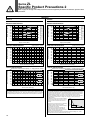
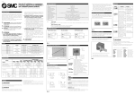
Selection
ZL112
ZL212
Exhaust characteristics
–80
–70
125
100
–60
on
mpti
onsu
Air c
–50
–40
75
50
–30
–20
25
–10
0
0.1
0.2
0.3
0.4
0.5
–100
–90
150
Vacuum pressure [kPa]
Vacuum pressure
rate
low
on f
i
t
c
Su
Suction flow rate [l/min (ANR)]
Air consumption [l/min (ANR)]
Vacuum pressure [kPa]
–100
–90
Vacuum pressure
–80
–70
–60
–40
100
–30
–20
0
0.6
Supply pressure: 0.4MPa
50
1.0
2.0
4.0
5.0
0
6.0
Supply pressure: 0.4MPa
–100
–90
Vacuum pressure [kPa]
Vacuum pressure [kPa]
3.0
Flow rate characteristics
–80
–70
–60
–50
–40
–30
–20
–80
–70
–60
–50
–40
–30
–20
–10
–10
20
30
40
50
60
70
80
–60
–53.3kPa
–50
–40kPa
–40
–26.7kPa
–30
–20
–13.3kPa
–10
3
4
60
100
140
180
220
260
300
Suction Flow rate [l/min (ANR)]
Time to reach vacuum
Measurement conditions/Tank capacity: 1l Supply pressure: 0.4MPa
–100
Vacuum pressure reached–89.3kPa
–90
–80kPa
–80
–66.7kPa
–70
2
20
130
Time to reach vacuum
1
0
90 100 110 120
5
6
7
8
9
10
11 12
Vacuum pressure in tank [kPa]
10
Suction flow rate [l/min(ANR)]
Vacuum pressure in tank [kPa]
150
–10
–100
–90
Measurement conditions/Tank capacity: 1l Supply pressure: 0.4MPa
–100
Vacuum pressure reached–89.3kPa
–90
–80kPa
–80
–66.7kPa
–70
–60
–53.3kPa
–50
–40kPa
–40
–30
–26.7kPa
–20
–13.3kPa
–10
0
1
Time to reach vacuum [S]
Viewing the graphs
2
3
4
5
Time to reach vacuum [S]
Viewing the graphs
The flow rate characteristics indicate the relationship between the vacuum pressure and
the suction flow rate of the ejector, and show that when the suction flow rate changes the
vacuum pressure also changes. In general, this indicates the relationship at the ejector's
standard operating pressure. In the graph, Pmax indicates the maximum vacuum
pressure, and Qmax indicates the maximum suction flow rate. These are the values that
are published as specifications in catalogs, etc. Changes in vacuum pressure are
explained below.
1. If the ejector's suction port is closed and sealed
Pmax
tight, the suction flow rate becomes "0" and the
vacuum pressure increases to the maximum
(Pmax).
2. If the suction port is opened and air is allowed to
flow (the air leaks), the suction flow rate
P1
increases and the vacuum pressure decreases.
(the condition of P1 and Q1)
Qmax
Q1
3. If the suction port is opened completely, the
Suction flow rate
suction flow rate increases to the maximum
(Qmax), while the vacuum pressure then drops
almost to "0" (atmospheric pressure).
When adsorbing work pieces which are permeable or subject to leakage, etc., caution
is required as the vacuum pressure will not be very high.
Vacuum pressure
The graphics indicate the time required to reach a vacuum pressure determined by adsorption conditions for work pieces, etc., starting from atmospheric pressure in a 1l sealed
tank. Approximately 8.8 seconds are necessary to attain a vacuum pressure of –89.3kPa.
16
200
Supply pressure [MPa]
Flow rate Characteristics
0
250
tion
ump
ons
c
r
i
A
–50
Supply pressure [MPa]
0
300
rate
low
ion f
Suct
Suction flow rate [l/min (ANR)]
Air consumption [l/min (ANR)]
Exhaust characteristics
6
SMC'S GLOBAL MANUFACTURING, DISTRIBUTION AND SERVICE NETWORK
EUROPE
EUROPE
NORTH AMERICA
AUSTRIA
SMC Pneumatik GmbH
CZECH
SMC Czech s.r.o.
DENMARK
SMC Pneumatik A/S
FINLAND
SMC Pneumatiikka OY
FRANCE
SMC Pneumatique SA
GERMANY
SMC Pneumatik GmbH
HUNGARY
SMC Hungary Kft.
IRELAND
SMC Pneumatics (Ireland) Ltd.
ITALY/ROMANIA
SMC Italia S.p.A.
NETHERLANDS
SMC Pnuematics BV.
NORWAY
SMC Pneumatics Norway A/S
RUSSIA
SMC Pneumatik LLC.
SLOVAKIA
SMC Slovakia s.r.o.
SLOVENIA
SMC Slovenia d.o.c.
SPAIN/PORTUGAL
SMC España, S.A.
SWEDEN
SMC Pneumatics Sweden AB
SWITZERLAND
SMC Pneumatik AG.
UK
SMC Pneumatics (U.K.) Ltd.
CANADA
SMC Pneumatics (Canada) Ltd.
MEXICO
SMC Corporation (Mexico) S.A. de C.V.
USA
SMC Pneumatics, Inc.
ASIA
SOUTH AMERICA
CHINA
SMC (China) Co., Ltd.
HONG KONG
SMC Pneumatics (Hong kong) Ltd.
INDIA
SMC Pneumatics (India) Pvt. Ltd.
MALAYSIA
SMC Pneumatics (S.E.A.) Sdn. Bhd.
PHILIPPINES
SMC Pneumatics (Philippines), Inc.
SINGAPORE
SMC Pneumatics (S.E.A.) Pte. Ltd.
SOUTH KOREA
SMC Pneumatics Korea Co., Ltd.
TAIWAN
SMC Pneumatics (Taiwan) Co., Ltd.
THAILAND
SMC Thailand Ltd.
ARGENTINA
SMC Argentina S.A.
BOLIVIA
SMC Pneumatics Bolivia S.R.L.
BRAZIL
SMC Pneumaticos Do Brazil Ltda.
CHILE
SMC Pneumatics (Chile) S.A.
VENEZUELA
SMC Neumatica Venezuela S.A.
OCEANIA
AUSTRALIA
SMC Pneumatics (Australia) Pty. Ltd.
NEW ZEALAND
SMC Pneumatics (N.Z.) Ltd.
1-16-4 Shimbashi, Minato-ku, Tokyo 105-0004 JAPAN
Tel: 03-3502-2740 Fax: 03-3508-2480
1st printing
March, 1999
D-SMC.L.A.
P-77.5 (JT)
Specifications are subject to change without prior notice
and any obligation on the part of the manufacturer.
Printed in Japan.