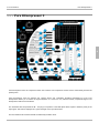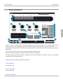
1
FLUX:: sound and picture development © 2007-2008 www.fluxhome.com
Table of Contents
Thanks
1
Conventions
2
How to Update
3
Dynamic Processors
5
Introduction to the Dynamic Processing
6
Why a Compressor ?
7
Why an Expander ?
8
Why a De-Compressor ?
9
Why a De-Expander ?
10
Why a Limiter ?
11
Alchemist
12
The Alchemist concept
13
The Parameters
14
General Settings and Display
15
Bands Settings and Display
20
Dynamic Sections Settings and Display
26
Solera II
29
The Solera Concept
30
Dynamic Processing Parameters Detailed
32
Pure Series II
43
Pure Compressor II
44
Pure Expander II
54
Pure DCompressor II
64
Pure DExpander II
74
Pure Limiter II
84
Bitter Sweet II
90
Equalizer
92
Epure II
Special Cases
FLUX User Interface
93
98
99
ii
The Preset Management
103
Common Specifications
106
Good to Know
107
Index
a
iii
1
1 Thanks
1
Thank You!
Thank you for purchasing a FLUX product.
FLUX offers a high-end line of audio plug-ins. Alchemist is the flagship for dynamic processing. Solera and the Pure Series
are a declination of particular dynamic sections from the Alchemist.
All our plug-in support AU, RTAS and VST compatible hosts for both Mac (OS X) and PC (Windows XP). A single dongle
(Flux or iLok) allows to use them on all platforms. Our plug-ins also exist in DSP version for the Pyramix DAW from Merging
Technologies.
Alchemist comes from 10-years-long cogitation about handling the audio dynamic, about the subjective loudness, about
compression. How to make a compressor, which can add loudness whilst keeping some airiness in the sound, which can
retain fast transients, subtle distinction and undertone? How to design a processor that combines both ease of use and
plenty of parameters?
How to make a processor that can retrieve lost dynamic? Or just to be able to add contrast, to increase low-level ambiance
or to sharpen the sound etc…
How can we imagine processing the dynamic without taking into account the sound Level?
How to compress the sound steadily without losing the “nuance” and pumping ? And so on.
Flux:: Dynamic Processors try to answer all these questions…
Our research on the dynamic has highlighted a major drawback in most equalizer implementations. Epure has been
designed to ensure a 110 dB signal to noise plus distortion ratio. This number affects directly the audio quality especially
when dealing with the dynamic.
Let’s use this optimized processing chain…
1
2
2 Conventions
On a screenshot every control features a number which also features into the function description title.
The commentaries will appear in italic type.
2
2
3
3 How to Update
Updating products
To download to the latest release of our plug-ins, you need to register your product(s)
Then you will be able to access the user download section by entering either the email address you entered during the
registration process, or your product reference.
Your product reference is it serial number if you have the Flux:: dongle key (it can be seen in the security manager
application, or your iLok.com user id if you use iLok to authorize our plug-ins.
In this user download area, you will reach your personal dongle update file, if available, as well as the latest software
package.
Select the one appropriate to your operating system to download it.
Install the Flux plug-ins.
Updating authorizations
If you have upgraded your authorizations, you have to transfer theses authorizations to your usb dongle.
If you use an iLok authorization key, go to www.iLok.com , and transfert the authorization to the iLok key by selecting
"Download Licenses" in the left menu.
If you use Flux:: dongle key, login to your personal download area (see above "How to Update to the latest release of your
products"), and in the "authorizations updates" part at the top of the page, follow the instructions.
Run SecurityManager.exe located in C:\Program Files\Flux\Plug-ins\Misc on PC.
On Mac, this application can be found into the plug-in installer disc image (dmg).
The Security Manager displays the serial number of the dongle that is currently plugged on your computer. From this
application press the update button. Select the dongle update you have previously saved on your hard drive, and press
open. That's done. The active licenses are listed and you're ready to use the Flux plug-ins.
If you are upgrading from a prior version before the release 1.2, be aware of your dongle requires an update in order to work.
If you haven't already received that update by e-mail, please contact Flux:: ([email protected]) to make your request.
The DSP version for VS3 / Pyramix is managed with Merging Technologies security system. Specific updates and
3
3
3
upgrades must be requested from Merging Technologies.
3
4
4
4 Dynamic Processors
The Flux:: Dynamic Processor family features "Alchemist", "Solera", "Pure Compressor", "Pure Expander", "Pure
DCompressor", "Pure DExpander" and "Pure Limiter".
All the Flux dynamic processors rely on the level (peak and RMS) detection like products from other companies. But all our
algorithms also use a dynamic value extracted from the input signal. This measurement of the dynamic when combined the
usual electrical measurement of RMS and peak values, allows to deeply process the sound while keeping a natural
character. The Flux processors feature many unusual parameters such as "Angel's Share" and "Hysteresis" which use the
measured dynamic value to adjust respectively ratio and threshold. Since a drum track has a totally different dynamic range
than a complete mix, many "Dynamic Profiles" can be selected depending of the audio material to process.
Here are some of the key features that make our plug-ins the best available for dynamic processing in the digital domain:
• An analog like metering. RMS values are more useful than dB-fs peak meter when setting a dynamic processor.
4
• The "Angel's Share" parameter takes into account the signal for intelligent relaxation of the compressor action.
• The "Hysteresis" parameter allows compressing and de-compressing, independently of the sound level and can be mixed
with the standard compression scheme
• The Auto Release features a unique algorithm that avoids typical pumping effect.
• The Advanced Release allows to set a minimum and a maximum release values including a speed control for the release
value variation.
• A delay line can be inserted in the signal path to produce a null attack time.
• 64 bit internal floating point processing.
• Sampling rate up to 384 KHz, DXD.
• Up to 8 channels.
• The A/B Compare and Morphing section enables ultra fast and precise operations.
By combining innovative features, the Flux dynamic processors are capable of emulating vintage equipment and creating
distinctive new sounds.
5
4.1 Introduction to the Dynamic
4.1 Introduction to the Dynamic Processing
What is the Dynamic Processing?
While mastering, mixing or recording, some uses of the dynamic processing are only utilitarian or trivial, but some are
creative. Our Processors can face any situation. Without forcing a particular sound coloration, they allow to achieve results
that can’t be reached with other plug-ins that just mimic usual hardware.
Presentation
Dynamic processing is the generic name for transformations that can be applied to the original dynamic of a signal. In other
words, it’s the range between the quietest and the loudest parts. Compressor, limiter, and noise gate are well known. But
some others also exist: expander, de-compressor, de-expander…
4
Most of the dynamic processing plug-ins feature a standard architecture by using series of particular processes one after the
other: Compressor, limiter and noise gate for example. The Alchemist and Solera architectures are different. They implement
4 different detectors and envelops generators in parallel and simultaneous: compressor, de-compressor, expander, and
de-expander. Every particular section also exists in the FLUX Pure Series.
6
4.1 Introduction to the Dynamic
Why a Compressor ?
4.1.1 Why a Compressor ?
A compressor is designed to reduce the dynamic range of an audio signal. That means difference between the quietest and
the loudest parts of the sound. This prevents the sound to disappear into a mix by the masking of surrounding louder
elements. This also prevents the sound to totally cover other instruments during loud parts.
The traditional approach is to reduce the signal level in a certain ratio (2 to 1, 4 to 1, 20 to 1…) as soon as a threshold value
is reached (-5 dB, 0 dB, +10dB…)
This threshold point can be smoothed with the knee value. If the knee is set to hard, there is no smoothing. If the knee is set
soft, the application of the set ratio reaches progressively around the threshold point.
A latency can be introduced before this gain reduction. This Attack time can be set from few milliseconds to hundreds
milliseconds.
A latency must be introduced after this gain reduction. This Release time can be set from tens millisecond to seconds.
Depending on the original dynamic content, those two time related parameters must be set carefully. A too short release
time may produce a pumping effect. It can be deliberate but it’s often an unwanted artifact. A too long attack time may
produce a totally ineffective compression because of its too slow action.
4
The compressor action produces a gain reduction expressed in dB. Usually this value is displayed on the compressor.
Once compressed the sound level has been diminished since louder parts have been minimized. The level needs to be
manually increased except if the compressor features a Make Up function. Now the processed sound doesn’t disappear in
the mix because its average level has been increased, and doesn’t cover other instruments because the level of its louder
parts has been reduced.
The processed signal is easier to mix because its level is more constant and the sound is denser.
If a compressor is set with a 20 to 1 ratio, it acts as a limiter. The sound level never exceeds the threshold value more than 1
dB for 20 dB of variation.
During mastering the compression is used in a different way. Except a limited correction of mixing errors, the goal is usually
to increase the density by controlling the peak levels to magnify the mid levels where the essence of the sound lives. A tight
control of the dynamic can balance a rhythm section and lead vocal to closely serve the artistic purpose.
The compressor action (blue area) is on the right hand side of the threshold. It’s under the diagonal of the 1:1 ratio (gain
reduction).
7
4.1 Introduction to the Dynamic
Why an Expander ?
4.1.2 Why an Expander ?
An expander behaves as the opposite of the compressor. The signal is toned down according to a certain ratio below the
threshold instead of above this point for the compressor.
The dynamic is expanded since original low levels are reduced once processed.
The difference between high levels and low levels is increased. Usually the expanders are used every time a signal needs to
be cleaned up from unwanted low level components.
Using a high ratio for the gain reduction can turn the expander into a noise gate. Below the threshold point, the signal is
gated.
The expander section of the Solera is used by the Pure Expander.
4
The expander action (blue area) is on the left hand side of the threshold. It’s under the diagonal of the 1:1 ratio (gain
reduction).
8
4.1 Introduction to the Dynamic
Why a De-Compressor ?
4.1.3 Why a De-Compressor ?
A de-compressor behaves as the opposite of the compressor. It increases the signal level above the threshold according to
the set ratio instead of reducing above this point for the compressor. It must be used to restore the dynamic of the signal.
This processing is very unusual for hardware dynamic processors because of the complexity of its implementation.
This processor can save a mastering session.
4
The de-compressor action (blue area)
9
4.1 Introduction to the Dynamic
Why a De-Expander ?
4.1.4 Why a De-Expander ?
A de-expander behaves as the opposite of the expander. It increases the signal level below the threshold according to the
set ratio instead of reducing below this point for the expander. It can be used to reduce the dynamic of the signal to magnify
low levels. This processing is very unusual for hardware dynamic processors because of the complexity of its
implementation.
4
The expander action (blue area)
10
4.1 Introduction to the Dynamic
Why a Limiter ?
4.1.5 Why a Limiter ?
A limiter is almost like a compressor set with an infinite ratio value. Since this process doesn't know nuances, most limiters
generate heavy sound artefacts.
Until you use it as a special effect, a limiter is supposed to be the very last stage of your audio processing chain.
A limiter can dramatically increase the average audio level without damaging the perceived audio quality when using a state
of the art algorithm.
A limiter is designed to avoid the signal to exceed a certain value. Basically, it's just a technical means to prevent overloads
in the audio chain when a high level is required and no excess is tolerated over this value.
4
The limiter action (blue area) is on the right hand side of the threshold. It’s under the diagonal of the 1:1 ratio (gain growth).
The blue area
11
4.2 Alchemist
4.2 Alchemist
Alchemist is the most powerful audio processor ever designed by Flux. It can subtly improve your mix or to totally transmute
the audio materials. This plug-in is a multi-band dynamic processor.
Based on the acclaimed Flux dynamic processing algorithms, Alchemist features a state-of-the-art IIR cross-over with
selectable slopes and variable corner frequencies. Every band owns a complete dynamic processing section including
compressor, expander, de-compressor, de-expander and a transient processor. The sound can be processed from single full
range to five bands.
Alchemist is the centerpiece to achieve your Great Work.
4
12
4.2 Alchemist
The Alchemist concept
4.2.1 The Alchemist concept
4
At first, the wideband signal is split into frequency bands by a slope adjustable cross-over. Each band is individually
processed for dynamic. For every frequency band, every dynamic processing section, the compressor, the de-compressor,
the expander and the de-expander features its own envelop generator including Angel's Share, Peak amount parameters,
Hysteresis and its threshold adjustment. For every frequency band, a transient manager can be inserted pre or post dynamic
processing. To achieve a total control on the audio signal, a MS management is available on every frequency band.
Then all the frequency bands are summed to rebuild a wideband processed signal. A soft clipper featuring a threshold for
soft knee, and a dry mix control are available.
Alchemist gathers in a single plug-in all the Flux science about filtering and dynamic processing.
13
4.2 Alchemist
The Parameters
4.2.2 The Parameters
4
14
4.2 Alchemist
The Parameters
4.2.2.1 General Settings and Display
This section manages the wide band behavior of the Alchemist plug-in.
It also controls the number of band of the processing (27) and the selection of the band setting panel (22).
4
General Settings
Input Gain (1)
Unit: dB - Value Range: -48 / +48 - Step: 0.01
15
4.2 Alchemist
The Parameters
Default Value: 0 dB
Sets the gain applied to the dynamic processing input.
Dry Mix (2)
Default Value: -144 dB
This slider controls the amount of the original signal that can be added to the processed audio. This feature is dedicated to
mastering works requiring both heavy processing and subtle control. The mix is done before the output gain.
Invert Phase (3)
Default Value: Off
When this button is engaged, the phase of the processed signal is inverted.
Output Gain (4)
Unit: dB - Value Range: -48 / +48 - Step: 0.01
Default Value: 0 dB
Sets the global gain applied to the dynamic processing output before the soft clipper.
4
Enable Clipper (5)
The Clipper is the very last stage of the processing chain.
Clipper Knee (6)
Unit: dB - Value Range: 0 / +3 - Step: 0.01
Default Value: 1 dB
Sets the smoothness of the transmission curve.
Bypass (7)
It's a global bypass.
Channel Processing Selector (8)
When operating on a multi-channel (surround) bus, all channels are processed by default, but it can be useful to remove
some channels from the processing for some reasons. This selector allows to keep the unchecked channels untouched.
This feature may be used if different settings are required. Several instancies of a plug-in can be used in series, each one
processing a particular channel with its own settings.
Channel Side Chain Routing (9)
When operating on a multi-channel bus, all channels are feeding the side chain by default, but it can be useful to prevent
some channels feeding the side chain for some reasons.
Band Selector (22)
The frequency band selection is done here.
16
4.2 Alchemist
The Parameters
It can also be done from the main display area.
Number of Band Control (27)
The Minus and Plus buttons allow to specify the number of frequency bands of the Alchemist from 1 to 5.
Reset Solo (21)
This button disables all engaged band solo.
General Display
Windows: Right-Click on the selected band accesses a specific contextual menu allowing to reset band(s) or copy the
band parameters to another band. An Auto Solo feature can be accessed when pressing the Ctrl key + Click on the desired
band.
MacOS: Right-Click or Ctrl + Click on the selected band accesses a specific contextual menu allowing to reset band(s) or
copy the band parameters to another band. An Auto Solo feature can be accessed when pressing the Command (Apple)
Key + Click on the desired band.
Input Peak Meter (10)
RMS Level Meter (11)
Vu-meters referenced to -16 dB Fs by default.
The up red line reflects the input signal.
The down red line reflects output signal
Output Peak Meter (12)
Output FFT Curve (13)
Auto Scale depending of the output signal. Maximum and minimum values (14) are displayed when the cursor is in the upper
part of the display area.
Link display (19)
The bands can have their parameters linked. Right-Click on the main display allows access to a contextual menu. Modifying
a setting of a linked band also modifies this setting for all linked bands.
Band Gain Handle (16)
The band display reflects both input and out gains.
The handle trims the output gain.
Shift + Click trims the input gain.
Double-Click reset the output gain to the default value.
17
4
4.2 Alchemist
The Parameters
Band Frequency Handle (15) (18)
Shift + Click enables fine trimming
Right-Click changes the filter slope
Double-Click resets the frequencies to the default values.
Global Band Handle (17)
Double-Click resets the frequencies to the default values.
Ctrl + Click auto-solos the selected band.
Band Activity (20)
It reflects the applied gain but also take account of the gain modification introduced by the Bitter Sweet section.
Low Pass Filter Frequency (26)
4
The value can be entered using the keyboard or the slider control.
Dragging the band handles is also possible from the main display.
Low Pass Filter Slope (25)
The value can be entered using the keyboard or the slider control.
Shift + Dragging the band handles is also possible from the main display.
Hi Pass Filter Slope (24)
The value can be entered using the keyboard or the slider control.
Shift + Dragging the band handles is also possible from the main display.
Hi Pass Filter Frequency (23)
The value can be entered using the keyboard or the slider control.
Dragging the band handles is also possible from the main display.
Preset Management
Preset Manager Access (78)
Loaded Preset Display (79)
A star signals a modified preset.
Save (80)
18
4.2 Alchemist
The Parameters
Save replaces the selected preset by a new one under the same name featuring the current settings. If you want to keep an
existing preset without your new modifications, just select an empty place into the preset list, enter a new name for this
modified preset featuring the current settings and press Save.
Recall (81)
Once a preset is selected from the preset list it must be explicitly loaded into section A or the section B by using the recall
button. A preset is effective only after it has been recalled.
Copy A / Copy B (82)
The current parameters of a section are copied to the other one. The section A or B is re-initialized with the current values
and the morphing slider is parked at 100% of the corresponding section.
Morphing Slider (83)
This horizontal slider has no unity nor specific value display. It allows to morph current settings between two loaded presets.
Double-click on one side of the slider area toggles between full A and full B settings.
4
The results of an in-between setting can be saved as a new preset.
A global preset including the two loaded presets and the morphing slider position can also be saved from preset
management window.
Automation Control of the Morphing Slider (84)
Default Value: Off
When this button is disabled, all the plug-in parameters values are recorded when writing automation. The morphing slider is
ignored.
When reading automation, if this button is disabled, all the plug-in parameters are controlled by the host automation except
the morphing slider.
When writing automation, if this button is engaged, ONLY the morphing slider value is recorded. No other parameter is
recorded.
When this button is engaged, ONLY the morphing slider value is applied when reading automation.
The Automation button must be engaged if the morphing slider has to be mapped on a control surface.
19
4.2 Alchemist
The Parameters
4.2.2.2 Bands Settings and Display
The main parameters of the band are gathered on this panel.
Alt + Click temporarily unlink the control when the band is linked.
4
Band Settings
Band Solo (47)
Solo the selected band(s)
Band Bypass (46)
Bypass the selected band.
Link (48)
Default: Enabled
By default the maximum value issued from all channels feeding the side chain is retained as source for processing.
This manner, the space information is kept for the processed multi-channel signals.
When disabled, every channel uses its own value for individual processing.
This configuration may be used in conjunction with the MS width section which encode the signal in MS before processing,
and decode at the output. This manner, the M signal can be processed while keeping the S channel untouched.
Input Gain (35)
20
4.2 Alchemist
The Parameters
Unit: dB - Value Range: -12 / +12 - Step: 0.01
Default Value: 0 dB
Sets the gain applied to the dynamic processing input of the selected band.
Output Gain (36)
Unit: dB - Value Range: -12 / +12 - Step: 0.01
Default Value: 0 dB
Sets the global gain applied to the dynamic processing output of the selected band.
Bitter Sweet On/Off (37)
When engaged, the Bitter Sweet processing is active.
Transient Amount (38)
Unit: % - Value Range: -100 to +100
Default Value: 0
4
On the Sweet side (left), transients are reduced.
It usually decreases percussive instruments in the mix.
On the Bitter side (right), transients are magnified.
It usually increases the percussive instruments in the mix.
Post Band Processing (40)
When engaged, the Bitter Sweet processing is done after the dynamic processing. Otherwise, it's done before the other
processing sections which are working in parallel.
Auto Gain Compensation (39)
When engaged, the output gain is compensated depending of the transient amount to produce an almost unity gain.
Bitter Sweet Period (42)
Unit: ms - Value Range: 3 to 450 ms
Default Value: 42 ms
This control sets the range of the time window used to detect transients that will be processed.
Bitter Sweet Sustain Release (43)
Unit: ms - Value Range: 0 to 500 ms
Default Value: 0 ms
This control sets the release time for the transient envelop.
Operation Mode Selector (41)
21
4.2 Alchemist
The Parameters
Main processes using regular stereo signal scheme and it is the only available mode for multi-channels operations.
Center engages internal MS encoder and processes only the Mid channel. After processing the sound is decoded back to
stereo.
Since the M channel usually features more enregy than the S channel, this mode allows to easily control the impact of the
sound.
Stereo engages internal MS encoder and processes only the Side channel. After processing the sound is decoded back to
stereo.
Since the S channel contains the spatial information, this mode allows to easily control the stereo imaging.
MS Width Control (59)
Unit: dB - Value Range: -6 / +6 - Step: 0.01
Default Value: 0
Sets the stereo width of the processed signal. A -6 dB value deceases the stereo width. A +6 dB value increases the
wideness of the stereo mix but can produce phase issue.
MS Mode On/Off (60)
4
Default Value: Off
Enables one MS encoding matrix at the input and one MS decoding matrix at the output of the dynamic processing in order
to control the stereo width of the mix. When engaged, the side chain is fed by a MS encoded signal that is reflected in the
display section. The M channel corresponds to the normal left channel. And the S channel corresponds to the normal right
channel This feature is only available when two channels (no more, no less) are processed.
Time Related Settings:
Delay (50)
Unit: ms - Value Range: 0 to 566.89 ms
Default Value: 0 ms
A delay reflecting the attack time can be introduced into the signal path in order to produce a zero attack time for the
dynamic processing. Shifting the delay value from the attack time allows to control transients. A delay value inferior to the
attack value lets peaks untouched by the processing.
Note that the different delay values of every band are automatically compensated. Alchemist can't be used to produce delay
based special effects.
Warning: Morphing between presets with different delay values produces sound artefacts.
Of course this delay introduces latency in the processing.
Auto Delay (49)
Default Value: Off
When enabled, the delay value is linked to the attack value. Be aware that the latency introduced by this function is now
equal to your attack time.
Warning: The latency introduced by this function equals the Attack time plus 1.35 ms @ 48 KHz.
22
4.2 Alchemist
The Parameters
Mode (51)
Default Value: Solera
8 different detection modes are available:
• Solera: The Attack setting also controls the integration time for RMS detection. When "Auto" is engaged for the delay
value, the produced attack time is zero.
• Solera Feed Backward: The Attack setting also controls the integration time for RMS detection which is done on the
output of the processor. This mode disables the Delay feature. Note also that the Solera Feed Backward prevents to use
the external side chain because it's the processed signal which feed the side chain.
• Classic Fast: The integration time for RMS detection is 10 ms with no direct relation with the Attack setting. But when
"Auto" is engaged for the delay value, the produced attack time is zero.
• Classic Medium: The integration time for RMS detection is 36 ms with no direct relation with the Attack setting. But when
"Auto" is engaged for the delay value, the produced attack time is zero.
• Classic Slow: The integration time for RMS detection is 100 ms with no direct relation with the Attack setting. But when
"Auto" is engaged for the delay value, the produced attack time is zero.
• Classic Feed Backward Fast: The integration time is 10 ms for RMS detection which is done on the output of the
processor. This mode disables the Delay feature.
• Classic Feed Backward Medium: The integration time is 36 ms for RMS detection which is done on the output of the
processor. This mode disables the Delay feature.
4
• Classic Feed Backward Slow: The integration time is 100ms for RMS detection which is done on the output of the
processor.This mode disables the Delay feature.
These Feed Backward modes have been inspired by vintage hardware architectures. they create a sort of auto regulation of
the processing which produces a naturally beefy sound.
Attack (52)
Unit: ms - Value Range: 1.45 ms to 544.22 ms
Default Value: 10.16 ms
Sets the attack time of the processing envelop. It also controls the manner the RMS value is computed from the incoming
signal in Solera modes.
Hold (53)
Unit: ms - Value Range: 0 ms / 500 ms.
Default Value: 0 ms
This parameter is the only one in the time related settings, that is independent per dynamic processor. The
compressor and the expander may have different hold time.
Used the Expander section, this setting allows very precise gating of drum tracks. It can also be used for creative purpose on
the other dynamic sections.
Release Mode (54)
Default Value: Auto
Three release modes are available for the envelop of the dynamic processing.
• Manual corresponds to the value you have set.
• Auto enables our specific algorithm to generate a signal dependent value to avoid typical pumping effects.
• Advanced gives access to two different values for release and to the control of the velocity of the variations between the
23
4.2 Alchemist
The Parameters
maximum and the minimum release values.
Release (55)
Unit: ms - Value Range: 1.45ms / 10884.35 ms
Default Value: 544.22 ms
Sets the manual release value and the maximum release value when in Advanced Mode.
Release Minimum (56)
Unit: ms - Value Range: 1.45ms / 5456.99 - Step: 0.01
Default Value: 1.45 ms
Sets the minimum release value when in Advanced Mode.
Dynamic Profile (57)
Default Value: Solera
Flux processors offer many different manners to detect the dynamic of the signal that is involved in the Auto and Advanced
modes for release.The Angel'Share and Hysteresis actions also rely on the detected dynamic.
• Solera > almost universal, great for vocals
4
• Beat 1 > hi pitched rhythm material
• Beat 2 > low pitched rhythm material, great for bass and bass drum
• Beat 3 > high dynamic range rhythm material, great for drums tracks
• Beat Average > rhythm material
• Max > very versatile and reactive
• Average > less sensitive to dynamic variations
Depending of the audio signal the differences can be subtle or obvious. There's no rule. Spending time experimenting these
Dynamic Profiles allows to benefit of all the sophistication of the Flux algorithms.
Dynamic Velocity (58)
Unit: % - Value Range: 10 / 1000 - Step: 1
Default Value: 50 %
Sets the speed of variation between Release Minimum and release Maximum when in Advanced Mode for release.
Band Display
Input Level Meter (28)
Vu-meter not peak-meter, referenced to -16 dB Fs by default, with auto scale depending of the threshold values.
When the MS Width section is engaged, the M (Mid) level is displayed on the left meter. S (Side) is displayed on the right
meter.
The green index reflects the threshold value.
Output Level Meter (29)
24
4.2 Alchemist
The Parameters
Vu-meter not peak-meter, referenced to -16 dB Fs by default, with auto scale depending of the threshold values.
When the MS Width section is engaged, the M (Mid) level is displayed on the left meter. S (Side) is displayed on the right
meter.
Resultant Envelop (30)
Vu-meter not peak-meter, referenced to -16 dB Fs by default. The scale is +/- 12 dB.
This is the compression, decompression, expander and de-expander summing envelop.
This display doesn't directly reflect the gain changes introduced by the Bitter Sweet section which can be placed pre or post
parallel dynamic processors.
Dynamic difference between in and out (31)
Vu-meter not peak-meter, referenced to -16 dB Fs by default. The scale is +/- 12 dB.
This display doesn't directly reflect the gain changes introduced by the Bitter Sweet section which can be placed pre or post
parallel dynamic processors.
4
Level difference between in and out (32)
Vu-meter not peak-meter, referenced to -16 dB Fs by default. The scale is +/- 12 dB.
This is the compression, decompression, expander and de-expander summing envelop which also takes account of the input
and output gains of the band.
This display doesn't reflect the gain changes introduced by the Bitter Sweet section.
The Bitter Sweet action can be observed on the main display.
Dynamic Activity Display (33)
No scale
The current Hysteresis Threshold value is reflected by two green lines on the Dynamic Activity display.
For Compressor and DCompressor sections, the hysteresis action is effective only when the orange Dynamic Activity ()
exceeds the area between the two green lines.
For Expander and DExpander sections, the hysteresis action is effective only when the orange Dynamic Activity () stays
inside the area between the two green lines.
Instant Release Value (34)
Auto Scale depending of the release value(s)
Resulting Transfer Curve (44)
Auto Scale depending of the threshold value(s)
Selected Band Display (45)
Reminder of the band selected using the general band selector
25
4.2 Alchemist
The Parameters
4.2.2.3 Dynamic Sections Settings and Display
Every band features four dynamic sections working is parallel.
Alt + Click temporarily unlink the control when the band is linked.
Dynamic Sections Settings:
4
Peak Detection Amount (61)
Unit: % - Value Range: 0 / 100 - Step: 1
Default Value: 0 %
Instant peak value can be added to the RMS signal feeding the detector section, making the dynamic processing more
sensitive to audio transients.
Angel's Share (62)
Unit: % - Value Range: 0 / 100 - Step: 1
Default Value: 0 %
This setting relaxes the ratio applied to the processor section when the detected signal dynamic raises.
This setting literally opens the sound, increases the dynamic impression and keeps some crest by adjusting in real time the
ratio of every dynamic processing section regarding both their current settings about ratio and the signal content (mainly
dynamic range). To start understanding this setting and easily hear it, take a full mixed drum kit or a complete mix with
punchy drums, set the compression threshold, ratio to get something near pumping or an aggressive compression. Then
increase the output gain to compensate the gain lost and then toggle between 0 and 100% of Angel Share. At 100 % you
should hear more air in the sound, more transient and less compression impression; especially in terms of attack.
Angel's Share Inverter (63)
When engaged, the behavior of the Angel's Share is inverted. The ratio value is increased depending of the detected signal
dynamic.
Hysteresis (64)
Unit: % - Value Range: 0 / 100 - Step: 1
Default Value: 0 %
26
4.2 Alchemist
The Parameters
Allows process the audio signal independently of the sound level but regarding the signal dynamic range. It is mixed with the
standard compression scheme.
Take a piece of full mixed music, set the ratio to 3-4 and the compression will start working. Now set the threshold of the
compressor to the maximum value, the compressor will stop working because the sound level will never reach the threshold.
Then increase the Hysteresis and you will see (and hear) the compression working again!!! Now decrease or increase the
input gain and you will see that the compression will continue to work equally; it's totally, completely independent of the
sound level and depends only on Ratio, Knee and sound content.
How can this be used? When you have too much dynamic in the sound, going for e.g. from -3, -6 dB Vu (or less) to +12 dB;
If you want to compress the low levels you will hear the sound "pumping" when the sound reaches the High levels and the
only thing to do with standard compressor will be to increase the threshold to rescue some airiness in the sound. But when
doing that the compressor will not work any more on the low levels and you will hear some sound differences (in term
density, live space, grain etc…) especially when the compressor starts working. With Hysteresis, adjust the threshold and
ratio on the High levels to what you think OK, then increase the Hysteresis (from 20 to 50 %) and listen now the low levels
and especially the transition between Low and High levels. You can also start increasing the ratio to increase the effect.
You'll then notice that the compression will always be active but can still take care of High, loud levels (unless you set 100%
hysteresis) and make the compression very smooth and no more pumping… In addition with the Angel Share function, you'll
be able to set a constant and very natural envelop that allows to increase low levels, low frequency and to keep important
transients.
4
Hysteresis Threshold (65)
Sets the gain range of the hysteresis parameter.
• Up: Increasing of the Hysteresis Threshold
• Down: Decreasing of the Hysteresis Threshold
The current Hysteresis Threshold value is reflected by two green lines on the Dynamic Activity display.
For Compressor and DCompressor sections, the hysteresis action is effective only when the orange Dynamic Activity (33)
exceeds the area between the two green lines.
For Expander and DExpander sections, the hysteresis action is effective only when the orange Dynamic Activity (33) stays
inside the area between the two green lines.
Hysteresis Maximum (66)
When engaged, the threshold for the processing is determined by the maximum values from RMS/peak detection OR from
the signal dynamic detection. The Hysteresis Threshold is still active, but the Hysteresis mix button is disabled.
This feature allows the whole process to be more reactive to the signal content. It worth being tried on drum tracks.
Threshold (67)
Unit: dB - Value Range: -32 to +16 (Compressor/DCompressor) -80 to +16 (Expander/DExpander)
Default Value: 0
Sets the threshold of the specific dynamic processing section. This dB scale refers to an RMS value.
The threshold effective value is modified by the Hysteresis, the Hysteresis Threshold and, the Hysteresis Maximum settings.
Ratio (68)
Unit: dB - Value Range: 1 to 10 - Step: 0.01
Default Value: 1
Sets the ratio of the specific dynamic processing section.
27
4.2 Alchemist
The Parameters
The ratio effective value is modified by the Angel's Share amount.
Infinite (69)
Sets the ratio to its maximum possible value.
Range (70)
Unit: dB - Value Range: 0 to 48/140/24/16 (Compressor/Expander/DCompressor/DExpander)
Default Value: 24/96/12/12
Sets the maximum allowed gain variation for a specific dynamic processing section.
Knee (71)
Unit: dB - Value Range: 0 / +24
Default Value: 0
Sets the smoothness of the transmission curve for the specific dynamic processing section. The curve is smoothed around
the threshold value of the dB amount set with the knee value.
Dynamic Section On/Off (72)
Activates the specific section.
Compressor Section Selector (74)
DCompressor Section Selector (75)
Expander Section Selector (76)
DExpander Section Selector (77)
Dynamic Section Display
Dynamic Section Activity (73)
12 dB scale
The gain is displayed from left to right for gain increase.
The gain is displayed from right to left for gain decrease.
28
4
4.3 Solera II
4.3 Solera II
Solera uses one detector and four parallel envelop generators that allows four different dynamic processing also in parallel:
compressor, de-compressor, expander and de-expander. The corresponding sections may be activated individually.
On top of these controls, you’ll find a display area that shows you the resultant dynamic curve, a parametric curve for the
side-chain EQ and from left to right:
• Input level (vu-meter not peak-meter, referenced to -16 dB Fs by default)
• Output level
• Resultant envelop (compression, de-compression, expansion, and de-expansion, and clipper activity)
• Dynamic difference between in and out
• Level difference between in and out
4
Just under these meters, you'll find the dynamic meter (in orange) and another one (blue segment) which represents the
release variation in auto-release and advanced modes (variation between fast release on the left to slow release on the
right).
29
4.3 Solera II
The Solera Concept
4.3.1 The Solera Concept
The idea is extremely simple: Taking into account the signal level isn’t enough. The signal dynamic is also a part of the
equation.
So our dynamic processors use two different ways to analyze the signal:
• The first one is a level detection based on peaks and RMS values. That's the base of the dynamic processing.
• The second one generates a dynamic value. It doesn't rely any more on the signal level since it's based on the signal
complexity.
This dynamic value is used in Solera when using the Angel's Share and the Hysteresis settings:
• Angel's Share is a mix control between the RMS detector and the dynamic detector. It relaxes ratio value depending of
the signal complexity. A lower ratio is applied to complex signal. Angel's Share is a sort of controlled auto ratio.
• Hysteresis is also a mix control between the RMS detector and the dynamic detector. But it affects the threshold value.
Hysteresis is a sort of controlled auto threshold.
The parameters are organized in three categories:
• Time constants (Delay, Attack, Release…).
4
• Spectral controls (the EQ section).
• Specific parameters (Angel’s Share, Hysteresis).
It’s useless and ineffective to try at all prices to use every section of the Solera. Only the sound achievement must be kept in
mind.
E.g:
• If you want to increase the room ambience on a dry conga track, the de-expander section is of great help, and the
expander section is of no help.
• If you need a pumping electric guitar, only the compressor section can do the job.
The Filters
The bottom right hand of the Solera features an area called Detector Equalizer. This section includes In, Solo, 1-2-3
selectors buttons and four knobs: Filter type, Gain, Frequency and Q Factor. This three band parametric corrector doesn’t
directly affect the audio signal but only the detection signal that drives the processing.
Despite the parameter values may seem extreme (Q-Factor up to 10, frequency above 20 KHz and cumulative gain), smooth
results can be achieved without any parasitic artifacts even when dealing with frequencies out of the audio spectrum. The
goal is to use the part of the correction included into the audio spectrum. It’s one of the secret of the “Air” corrector featuring
on some vintage audio gears.
Solera owns 3 bands of equalization inserted in its detector channel but isn’t a multi-band processor. The wide-range
processing ensures a perfect accuracy in terms of phase and propagation time. Filtering the control signal upstream of the
envelop gain generation allows to control the overall tonal balance by increasing or decreasing the processing for a
particular part of the audio spectrum. Reducing the gain for the low frequencies before detection will increase low
frequencies in the processed signal if the processing settings reduce the gain according to the signal level. With this
configuration, increasing the gain for the high frequencies, makes the processing more sensitive to this particular part of the
audio spectrum and turns the Solera into a sibilant controller. More generally, equalizing the signal feeding the detector
allows to shape the processing action for particular frequencies.
The MS Mode
30
4.3 Solera II
The Solera Concept
Like some high-end mastering compressors, Solera features a M/S (Mid/Side) encoder / decoder section. It encodes the
stereo inputs by summing left and right channels to produce the Mid and the right channel from the left channel to produce
the Side signal. M is now the mono component of the signal (bass drum, lead vocal, bass…). S describes the stereo
component of the signal. Processing both M and S components with a compressor allows to achieve unfeasible results for a
regular stereo device.
Classical case: One centered bass drum with a fluctuating level surrounded by a synthesizer pad. The M channel featuring
the bass drum can be processed without affecting the S channel featuring the Synthesizer pad.
Changing the S gain when decoding allows to control the stereo width (MS Width in Solera). The MS mode of the Solera
must only be used with stereo signal. Already MS encoded signal must be avoided if this mode is engaged.
Presets and Morphing
The lower section of the Solera features two identical preset sections. Every section includes a Recall, a Save, and a list
access buttons. Between sections A and B a horizontal slider controls the morphing of the settings between the two
sections. This architecture allows to load two different presets and to easily experiment intermediate settings. An
intermediate result can be saved as a new preset that can be used for a new morphing.
4
Auto Release
When Auto Release is selected as Release Mode, the release time varies automatically. This variation is needed to avoid
both pumping effect due to a too short value, and excessive processing due to a too long value. This automatic variation
prevents a very sensitive setting of the release time by user in most cases. The release value can be accessed in Manual
and Advanced modes.
Delay
A delay line can be inserted on the processed signal. Its main function is to produce null attack time for processing when the
delay value equals the Attack time. The Auto button automatically sets the delay value according to the Attack time. Setting
the delay time lower than the Attack time preserves the peaks from the processing action.
Dry Mix
The original signal can be mixed with the processed signal. The original audio peaks are kept to preserve the sensitive
information of the sound attacks and is added to the processed sound touching the body of every notes.
Note that this mix function takes into account the delay that may be introduced by the processing. The summation is done
before the clipper stage. The displayed gain also reflects the Dry Mix setting.
31
4.3 Solera II
Dynamic Processing Parameters Detailed
4.3.2 Dynamic Processing Parameters Detailed
4
General Settings:
Input Gain (1)
Unit: dB - Value Range: -48 / +48 - Step: 0.01
Default Value: 0 dB
Sets the gain applied to the dynamic processing input.
Dry Mix (2)
32
4.3 Solera II
Dynamic Processing Parameters Detailed
Default Value: -144 dB
This slider controls the amount of the original signal that can be added to the processed audio. This feature is dedicated to
mastering works requiring both heavy processing and subtle control. The mix is done before the output gain.
Output Gain (3)
Unit: dB - Value Range: -48 / +48 - Step: 0.01
Default Value: 0 dB
Sets the global gain applied to the dynamic processing output.
Invert Phase (4)
Default Value: Off
When this button is engaged, the phase of the processed signal is inverted.
This 180° phase shift is also applied on the Solo of the detector Equalizer.
Enable Clipper (5)
4
The Clipper is the very last stage of the processing chain.
Clipper Knee (6)
Unit: dB - Value Range: 0 / +3 - Step: 0.01
Default Value: 1 dB
Sets the smoothness of the transmission curve.
Link (7)
Default: Enabled
By default the maximum value issued from all channels feeding the side chain is retained as source for processing.
This manner, the space information is kept for the processed multi-channel signals.
When disabled, every channel uses its own value for individual processing.
This configuration may be used in conjunction with the MS width section which encode the signal in MS before processing,
and decode at the output. This manner, the M signal can be processed while keeping the S channel untouched.
Bypass (8)
It's a global bypass.
Channel Processing Selector (9)
When operating on a multi-channel bus, all channels are processed by default, but it can be useful to remove some channels
from the processing for some reasons. This selector allows to keep the unchecked channels untouched.
This feature may be used if different settings are required. Several instancies of a plug-in can be used in series, each one
processing a particular channel with its own settings.
Channel Side Chain Routing (10)
33
4.3 Solera II
Dynamic Processing Parameters Detailed
When operating on a multi-channel bus, all channels are feeding the side chain by default, but it can be useful to prevent
some channels feeding the side chain for some reasons. Note also that the external side chain (EX), when activated,
disables the internal side chain.
Here are the different behaviors for external side chain depending of the host applications:
• Audio Unit in Live and Logic > The EX button is enabled by default even if no side chain buss is specified in the plug-in
handler. All channels are summed and applied as external side chain automatically by the host application. This EX
button must be disabled if the internal side chain management of the plug-in is preferred because it isn't phase sensitive.
• RTAS > The EX button is only active if a side chain buss is selected from the plug-in handler. To use the internal side
chain of the plug -in no external side chain must be selected.
• VST > The external side chain bus must be routed as a particular channel of the mixer slice on which the plug-in is
inserted (processing a stereo signal requires 3 channels). Then, from the plug-in interface, this particular must be
selected as side chain source. The EX button never appears. This allows to mix both internal and external signals for side
chain.
MS Width Control (20)
Unit: dB - Value Range: -6 / +6 - Step: 0.01
Default Value: 0
Sets the stereo width of the processed signal. A -6 dB value deceases the stereo width. A +6 dB value increases the
wideness of the stereo mix but can produce phase issue.
MS Mode On/Off (21)
Default Value: Off
Enables one MS encoding matrix at the input and one MS decoding matrix at the output of the dynamic processing in order
to control the stereo width of the mix. When engaged, the side chain is fed by a MS encoded signal that is reflected in the
display section. M channel corresponds to the normal left channel. And the S channel corresponds to the normal right
channel This feature is only available when two channels (no more, no less) are processed.
Time Related Settings:
Delay (47)
Unit: ms - Value Range: 0 to 566.89 ms
Default Value: 0 ms
A delay reflecting the attack time can be introduced into the signal path in order to produce a zero attack time for the
dynamic processing. Shifting the delay value from the attack time allows to control transients. A delay value inferior to the
attack value lets peaks untouched by the processing.
Note that the different delay values of every band are automatically compensated. Alchemist can't be used to produce delay
based special effects.
Warning: Morphing between presets with different delay values produces sound artefacts.
Of course this delay introduces latency in the processing.
Auto Delay (46)
Default Value: Off
34
4
4.3 Solera II
Dynamic Processing Parameters Detailed
When enabled, the delay value is linked to the attack value. Be aware that the latency introduced by this function is now
equal to your attack time.
Warning: The latency introduced by this function equals the Attack time plus 1.35 ms @ 48 KHz.
Mode (48)
Default Value: Solera
8 different detection modes are available:
• Solera: The Attack setting also controls the integration time for RMS detection. When "Auto" is engaged for the delay
value, the produced attack time is zero.
• Solera Feed Backward: The Attack setting also controls the integration time for RMS detection which is done on the
output of the processor. This mode disables the Delay feature. Note also that the Solera Feed Backward prevents to use
the external side chain because it's the processed signal which feed the side chain.
• Classic Fast: The integration time for RMS detection is 10 ms with no direct relation with the Attack setting. But when
"Auto" is engaged for the delay value, the produced attack time is zero.
• Classic Medium: The integration time for RMS detection is 36 ms with no direct relation with the Attack setting. But when
"Auto" is engaged for the delay value, the produced attack time is zero.
• Classic Slow: The integration time for RMS detection is 100 ms with no direct relation with the Attack setting. But when
"Auto" is engaged for the delay value, the produced attack time is zero.
4
• Classic Feed Backward Fast: The integration time is 10 ms for RMS detection which is done on the output of the
processor. This mode disables the Delay feature. Note also that the Feed Backward mode prevents to use the external
side chain because it's the processed signal which feed the side chain.
• Classic Feed Backward Medium: The integration time is 36 ms for RMS detection which is done on the output of the
processor. Note also that the Feed Backward mode prevents to use the external side chain because it's the processed
signal which feed the side chain.
• Classic Feed Backward Slow: The integration time is 100ms for RMS detection which is done on the output of the
processor. Note also that the Feed Backward mode prevents to use the external side chain because it's the processed
signal which feed the side chain.
These Feed Backward modes have been inspired by vintage hardware architectures. they create a sort of auto regulation of
the processing which produces a naturally beefy sound.
Attack (49)
Unit: ms - Value Range: 1.45 ms to 544.22 ms
Default Value: 10.16 ms
Sets the attack time of the processing envelop. It also controls the manner the RMS value is computed from the incoming
signal.
Hold (50)
Unit: ms - Value Range: 0 ms / 500 ms.
Default Value: 0 ms
This parameter is the only one in the time related settings, that is independent per dynamic processor. The
compressor and the expander may have different hold time.
Used in the Expander section, this setting allows very precise gating of drum tracks. It can also be used for creative purpose
on the other dynamic sections.
Release Mode (51)
35
4.3 Solera II
Dynamic Processing Parameters Detailed
Default Value: Auto
Three release modes are available for the envelop of the dynamic processing.
• Manual corresponds to the value you have set.
• Auto enables our specific algorithm to generate a signal dependent value to avoid typical pumping effects.
• Advanced gives access to two different values for release and to the control of the velocity of the variations between the
maximum and the minimum release values.
Release (52)
Unit: ms - Value Range: 1.45ms / 10884.35 ms
Default Value: 544.22 ms
Sets the manual release value and the maximum release value when in Advanced Mode.
Release Minimum (53)
Unit: ms - Value Range: 1.45ms / 5456.99 - Step: 0.01
Default Value: 1.45 ms
Sets the minimum release value when in Advanced Mode.
4
Dynamic Profile (54)
Default Value: Solera
Flux processors offer many different manners to detect the dynamic of the signal that is involved in the Auto and Advanced
modes for release.The Angel's Share and Hysteresis actions also rely on the detected dynamic.
• Solera > almost universal, great for vocals
• Beat 1 > hi pitched rhythm material
• Beat 2 > low pitched rhythm material, great for bass and bass drum
• Beat 3 > high dynamic range rhythm material, great for drums tracks
• Beat Average > rhythm material
• Max > very versatile and reactive
• Average > less sensitive to dynamic variations
Depending of the audio signal the differences can be subtle or obvious. There's no rule. Spending time experimenting these
Dynamic Profiles allows to benefit of all the sophistication of the Flux algorithms.
Dynamic Velocity (55)
Unit: % - Value Range: 10 / 1000 - Step: 1
Default Value: 50 %
Sets the speed of variation between Release Minimum and release Maximum when in Advanced Mode for release.
Dynamic Sections Settings:
Peak Detection Amount (22)
Unit: % - Value Range: 0 / 100 - Step: 1
36
4.3 Solera II
Dynamic Processing Parameters Detailed
Default Value: 0 %
Instant peak value can be added to the RMS signal feeding the detector section, making the dynamic processing more
sensitive to audio transients.
Angel's Share (23)
Unit: % - Value Range: 0 / 100 - Step: 1
Default Value: 0 %
This setting relaxes the ratio applied to the processor section when the detected signal dynamic raises.
This setting literally opens the sound, increases the dynamic impression and keeps some crest by adjusting in real time the
ratio of every dynamic processing section regarding both their current settings about ratio and the signal content (mainly
dynamic range). To start understanding this setting and easily hear it, take a full mixed drum kit or a complete mix with
punchy drums, set the compression threshold, ratio to get something near pumping or an aggressive compression. Then
increase the output gain to compensate the gain lost and then toggle between 0 and 100% of Angel Share. At 100 % you
should hear more air in the sound, more transient and less compression impression; especially in terms of attack.
Angel's Share Inverter (24)
When engaged, the behavior of the Angel's Share is inverted. The ratio value is increased depending of the detected signal
dynamic.
Hysteresis (25)
Unit: % - Value Range: 0 / 100 - Step: 1
Default Value: 0 %
Allows process the audio signal independently of the sound level but regarding the signal dynamic range. It is mixed with the
standard compression scheme.
Take a piece of full mixed music, set the ratio to 3-4 and the compression will start working. Now set the threshold of the
compressor to the maximum value, the compressor will stop working because the sound level will never reach the threshold.
Then increase the Hysteresis and you will see (and hear) the compression working again!!! Now decrease or increase the
input gain (in Solera or before, as you want) and you will see that the compression will continue to work equally; it's totally,
completely independent of the sound level and depends only on Ratio, Knee and sound content.
How can this be used? When you have too much dynamic in the sound, going for e.g. from -3, -6 dB Vu (or less) to +12 dB;
If you want to compress the low levels you will hear the sound "pumping" when the sound reaches the High levels and the
only thing to do with standard compressor will be to increase the threshold to rescue some airiness in the sound. But when
doing that the compressor will not work any more on the low levels and you will hear some sound differences (in term
density, live space, grain etc…) especially when the compressor starts working. With Solera Hysteresis, adjust the threshold
and ratio on the High levels to what you think OK, then increase the Hysteresis (from 20 to 50 %) and listen now the low
levels and especially the transition between Low and High levels. You can also start increasing the ratio to increase the
effect. You'll then notice that the compression will always be active but can still take care of High, loud levels (unless you set
100% hysteresis) and make the compression very smooth and no more pumping… In addition with the Angel Share function,
you'll be able to set a constant and very natural envelop that allows to increase low levels, low frequency and to keep
important transients.
Hysteresis Threshold (26)
Sets the gain range of the hysteresis parameter.
• Up: Increasing of the Hysteresis action
• Down: Decreasing of the Hysteresis action
37
4
4.3 Solera II
Dynamic Processing Parameters Detailed
The current Hysteresis Threshold value is reflected by two green lines on the Dynamic Activity display.
For Compressor and DCompressor sections, the hysteresis action is effective only when the orange Dynamic Activity (18)
exceeds the area between the two green lines.
For Expander and DExpander sections, the hysteresis action is effective only when the orange Dynamic Activity (18) stays
inside the area between the two green lines.
Hysteresis Maximum (27)
When engaged, the threshold for the processing is determined by the maximum values from RMS/peak detection OR from
the signal dynamic detection. The Hysteresis Threshold is still active, but the Hysteresis mix button is disabled.
This feature allows the whole process to be more reactive to the signal content. It worth to be tried on drum tracks.
Threshold (28)
Unit: dB - Value Range: -32 to +16 (Compressor/DCompressor) -80 to +16 (Expander/DExpander)
Default Value: 0
Sets the threshold of the specific dynamic processing section. This dB scale refers to an RMS value.
The threshold effective value is modified by the Hysteresis, the Hysteresis Threshold and, the Hysteresis Maximum settings.
Ratio (29)
Unit: dB - Value Range: 1 to 10 - Step: 0.01
Default Value: 1
Sets the ratio of the specific dynamic processing section.
The ratio effective value is modified by the Angel's Share amount.
Infinite (30)
Sets the ratio to its maximum possible value depending of the dynamic section
The DCcompressor section is limited 12 when this button is engaged.
Range (31)
Unit: dB - Value Range: 0 to 48/140/24/16 (Compressor/Expander/DCompressor/DExpander)
Default Value: 24/96/12/12
Sets the maximum allowed gain variation for a specific dynamic processing section.
Knee (32)
Unit: dB - Value Range: 0 / +24
Default Value: 0
Sets the smoothness of the transmission curve for the specific dynamic processing section. The curve is smoothed around
the threshold value of the dB amount set with the knee value.
Dynamic Section On/Off (33)
38
4
4.3 Solera II
Dynamic Processing Parameters Detailed
Activates the specific section.
Compressor Section Selector (35)
DCompressor Section Selector (36)
Expander Section Selector (37)
DExpander Section Selector (38)
Dynamic Section Display
Dynamic Section Activity (34)
12 dB scale
4
The gain is displayed from left to right for gain increase.
The gain is displayed from right to left for gain decrease.
Display
Input Level Meter (13)
Vu-meter not peak-meter, referenced to -16 dB Fs by default, with auto scale depending of the threshold values.
When the MS Width section is engaged, the M (Mid) level is displayed on the left meter. S (Side) is displayed on the right
meter.
The green index reflects the threshold value.
Output Level Meter (14)
Vu-meter not peak-meter, referenced to -16 dB Fs by default, with auto scale depending of the threshold values.
When the MS Width section is engaged, the M (Mid) level is displayed on the left meter. S (Side) is displayed on the right
meter.
Resultant Envelop (15)
Vu-meter not peak-meter, referenced to -16 dB Fs by default. The scale is +/- 12 dB.
This is the compression, decompression, expander and de-expander summing envelop.
Dynamic difference between in and out (16)
Vu-meter not peak-meter, referenced to -16 dB Fs by default. The scale is +/- 12 dB.
39
4.3 Solera II
Dynamic Processing Parameters Detailed
Level difference between in and out (17)
Vu-meter not peak-meter, referenced to -16 dB Fs by default. The scale is +/- 12 dB.
This is the compression, decompression, expander and de-expander summing envelop which also takes account of the input
and output gains of the band.
Dynamic Activity Display (18)
No scale
The current Hysteresis Threshold value is reflected by two green lines on the Dynamic Activity display.
For Compressor and DCompressor sections, the hysteresis action is effective only when the orange Dynamic Activity ()
exceeds the area between the two green lines.
For Expander and DExpander sections, the hysteresis action is effective only when the orange Dynamic Activity () stays
inside the area between the two green lines.
Instant Release Value (19)
4
Auto Scale depending of the release value(s)
Resulting Transfer Curve (11)
Auto Scale depending of the threshold value(s)
The Side Chain EQ Section:
The band selection can be done with the 1, 2, 3 switches or directly from the graphic display.
All band parameters can also be set using switches and knobs or from the EQ-Curve graphic display as described below.
A Double-click in the graphic display area of the EQ-Curve magnifies it. A new Double-click toggles it back to a reduced size.
From a Right-Click on this area, the behavior of the vertical scale can be selected. Auto, 6 dB, 12 dB and 24 dB are the
possible choices.
In (39)
Default Value: 0ff
Enables the complete EQ section on detector section.
Solo (40)
Default Value: 0ff
The equalized detector signal can be monitored through the plug-in output when the solo button is enabled.
1-2-3 (41)
Default Value: none
Three equalization bands are available on the detector section. Each can be selected to use the parameter knobs for
40
4.3 Solera II
Dynamic Processing Parameters Detailed
settings. Note that a graphic editing is also available from the graphic curve display.
Filter Type (42)
Default Value: peak
• 12 dB per octave high pass filter
• Low shelving
• Parametric
• High shelving
• 12 dB per octave low pass filter
Are possible for every band
Gain (43)
Unit: dB - Value Range: -24 / +24 - Step: 0.01
Default Value: 0
Sets the gain for the selected band.
4
Frequency (44)
Unit: Hz - Value Range: 5 / 22K - Step: variable
Default Value: 100 / 500 / 2000
Sets the center frequency for the selected band.
Q-Factor (45)
Value Range: 1 / 100 - Step: 0.22
Default Value: 10
Sets the quality factor of the selected band if the filter type is parametric.
Preset Management
Preset Manager Access (56)
Loaded Preset Preset Display (57)
Save (58)
Save replaces the selected preset by a new one under the same name featuring the current settings. If you want to keep an
existing preset without your new modifications, just select an empty place into the preset list, enter a new name for this
modified preset featuring the current settings and press Save.
Recall (59)
41
4.3 Solera II
Dynamic Processing Parameters Detailed
Once a preset is selected from the preset list it must be explicitly loaded into section A or the section B by using the recall
button. A preset is effective only after it has been recalled.
Copy A / Copy B (60)
The current parameters of a section are copied to the other one. The section A or B is re-initialized with the current values
and the morphing slider is parked at 100% of the corresponding section.
Morphing Slider (61)
This horizontal slider has no unity nor specific value display. It allows to morph current settings between two loaded presets.
Double-click on one side of the slider area toggles between full A and full B settings.
The results of an in-between setting can be saved as a new preset.
A global preset including the two loaded presets and the morphing slider position can also be saved from preset
management window.
Automation Control of the Morphing Slider (62)
4
Default Value: Off
When writing automation, if this button is engaged, ONLY the morphing slider value is recorded. No other parameter is
recorded.
When this button is engaged, ONLY the morphing slider value is applied when reading automation.
When this button is disabled, all the plug-in parameters values are recorded when writing automation. The morphing slider is
ignored.
When reading automation, if this button is disabled, all the plug-in parameters are controlled by the host automation except
the morphing slider.
The Automation button must be engaged if the morphing slider has to be mapped on a control surface.
42
4.4 Pure Series II
4.4 Pure Series II
4
43
4.4 Pure Series II
Pure Compressor II
4.4.1 Pure Compressor II
4
Pure Compressor is the compressor section of the Solera. A compressor must be used to automatically reduce the gain
above the Threshold
It uses the exclusive “Angel’s Share” and “Hysteresis” algorithms developed by FLUX.
Pure Compressor produces a wide range of compressions from ultra clean subtle compressions to classic heavy pumping
ones. It’s up to your artistic choices not to the technology limitations.
The Threshold value is expressed in dB – The plug-in compares it to the RMS (Root Mean Square or effective power) of the
input signal. This value is displayed as a green rectangle on the input level meter.
The level variations above the threshold are affected by the Ratio value.
For a 1:1 compression ratio, the processed signal isn’t affected by the processing: A 1 dB variation above the threshold at
44
4.4 Pure Series II
Pure Compressor II
the input is reflected by a 1 dB variation at the output.
Let’s apply now a 3:1 ratio. If the input signal rises above 3 dB the threshold value, the output signal rises only from 1 dB:
Here is the compressor action. The input signal gain is reduced by a 3:1 ratio above the threshold point.
The Knee sets how progressive is the start up of the compressor action – In other words, It smoothes the transition point
between no processing and full processing. If the Knee value expressed in dB is increased, the progressiveness of the
action will be spread below and above the threshold point.
The Range value sets the processing maximum action. No gain variation can exceed this value.
General Settings:
Input Gain (1)
Unit: dB - Value Range: -48 / +48 - Step: 0.01
Default Value: 0 dB
4
Sets the gain applied to the dynamic processing input.
Output Gain (2)
Unit: dB - Value Range: -48 / +48 - Step: 0.01
Default Value: 0 dB
Sets the global gain applied to the dynamic processing output.
Invert Phase (3)
Default Value: Off
When this button is engaged, the phase of the processed signal is inverted.
This 180° phase shift is also applied on the Solo of the detector Equalizer.
Dry Mix (4)
Default Value: -144 dB
This slider controls the amount of the original signal that can be added to the processed audio. This feature is dedicated to
mastering works requiring both heavy processing and subtle control. The mix is done before the output gain.
Clipper Knee (5)
Unit: dB - Value Range: 0 / +3 - Step: 0.01
Default Value: 1 dB
Sets the smoothness of the transmission curve.
Enable Clipper (6)
The Clipper is the very last stage of the processing chain.
45
4.4 Pure Series II
Pure Compressor II
Bypass (7)
It's a global bypass.
Channel Processing Selector (8)
When operating on a multi-channel bus, all channels are processed by default, but it can be useful to remove some channels
from the processing for some reasons. This selector allows to keep the unchecked channels untouched.
This feature may be used if different settings are required. Several instancies of a plug-in can be used in series, each one
processing a particular channel with its own settings.
Channel Side Chain Routing (9)
When operating on a multi-channel bus, all channels are feeding the side chain by default, but it can be useful to prevent
some channels feeding the side chain for some reasons. Note also that the external side chain (EX), when activated,
disables the internal side chain.
Here are the different behaviors for external side chain depending of the host applications:
• Audio Unit in Live and Logic > The EX button is enabled by default even if no side chain buss is specified in the plug-in
handler. All channels are summed and applied as external side chain automatically by the host application. This EX
button must be disabled if the internal side chain management of the plug-in is preferred because it isn't phase sensitive.
• RTAS > The EX button is only active if a side chain buss is selected from the plug-in handler. To use the internal side
chain of the plug -in no external side chain must be selected.
• VST > The external side chain bus must be routed as a particular channel of the mixer slice on which the plug-in is
inserted (processing a stereo signal requires 3 channels). Then, from the plug-in interface, this particular must be
selected as side chain source. The EX button never appears. This allows to mix both internal and external signals for side
chain.
MS Width Control (10)
Unit: dB - Value Range: -6 / +6 - Step: 0.01
Default Value: 0
Sets the stereo width of the processed signal. A -6 dB value deceases the stereo width. A +6 dB value increases the
wideness of the stereo mix but can produce phase issue.
MS Mode On/Off (11)
Default Value: Off
Enables one MS encoding matrix at the input and one MS decoding matrix at the output of the dynamic processing in order
to control the stereo width of the mix. When engaged, the side chain is fed by a MS encoded signal that is reflected in the
display section. M channel corresponds to the normal left channel. And the S channel corresponds to the normal right
channel This feature is only available when two channels (no more, no less) are processed.
Link (12)
Default: Enabled
By default the maximum value issued from all channels feeding the side chain is retained as source for processing.
This manner, the space information is kept for the processed multi-channel signals.
When disabled, every channel uses its own value for individual processing.
This configuration may be used in conjunction with the MS width section which encode the signal in MS before processing,
46
4
4.4 Pure Series II
Pure Compressor II
and decode at the output. This manner, the M signal can be processed while keeping the S channel untouched.
Smooth (13)
Default: Enabled
When engaged, the side chain is set to preserve bass frequencies from excessive processing.
Removing the Smooth profile is usually a great help when trying to smash a kick drum.
Time Related Settings:
Delay (14)
Unit: ms - Value Range: 0 to 566.89 ms
Default Value: 0 ms
A delay reflecting the attack time can be introduced into the signal path in order to produce a zero attack time for the
dynamic processing. Shifting the delay value from the attack time allows to control transients. A delay value inferior to the
attack value lets peaks untouched by the processing.
Note that the different delay values of every band are automatically compensated. Alchemist can't be used to produce delay
based special effects.
Warning: Morphing between presets with different delay values produces sound artefacts.
Of course this delay introduces latency in the processing.
Auto Delay (15)
Default Value: Off
When enabled, the delay value is linked to the attack value. Be aware that the latency introduced by this function is now
equal to your attack time.
Warning: The latency introduced by this function equals the Attack time plus 1.35 ms @ 48 KHz.
Mode (16)
Default Value: Solera
8 different detection modes are available:
• Solera: The Attack setting also controls the integration time for RMS detection. When "Auto" is engaged for the delay
value, the produced attack time is zero.
• Solera Feed Backward: The Attack setting also controls the integration time for RMS detection which is done on the
output of the processor. This mode disables the Delay feature. Note also that the Solera Feed Backward prevents to use
the external side chain because it's the processed signal which feed the side chain.
• Classic Fast: The integration time for RMS detection is 10 ms with no direct relation with the Attack setting. But when
"Auto" is engaged for the delay value, the produced attack time is zero.
• Classic Medium: The integration time for RMS detection is 36 ms with no direct relation with the Attack setting. But when
"Auto" is engaged for the delay value, the produced attack time is zero.
• Classic Slow: The integration time for RMS detection is 100 ms with no direct relation with the Attack setting. But when
"Auto" is engaged for the delay value, the produced attack time is zero.
• Classic Feed Backward Fast: The integration time is 10 ms for RMS detection which is done on the output of the
47
4
4.4 Pure Series II
Pure Compressor II
processor. This mode disables the Delay feature. Note also that the Feed Backward mode prevents to use the external
side chain because it's the processed signal which feed the side chain.
• Classic Feed Backward Medium: The integration time is 36 ms for RMS detection which is done on the output of the
processor. Note also that the Feed Backward mode prevents to use the external side chain because it's the processed
signal which feed the side chain.
• Classic Feed Backward Slow: The integration time is 100ms for RMS detection which is done on the output of the
processor. Note also that the Feed Backward mode prevents to use the external side chain because it's the processed
signal which feed the side chain.
These Feed Backward modes have been inspired by vintage hardware architectures. they create a sort of auto regulation of
the processing which produces a naturally beefy sound.
Attack (17)
Unit: ms - Value Range: 1.45 ms to 544.22 ms
Default Value: 10.16 ms
Sets the attack time of the processing envelop. It also controls the manner the RMS value is computed from the incoming
signal.
Hold (18)
4
Unit: ms - Value Range: 0 ms / 500 ms.
Default Value: 0 ms
Release Mode (19)
Default Value: Auto
Three release modes are available for the envelop of the dynamic processing.
• Manual corresponds to the value you have set.
• Auto enables our specific algorithm to generate a signal dependent value to avoid typical pumping effects.
• Advanced gives access to two different values for release and to the control of the velocity of the variations between the
maximum and the minimum release values.
Release (20)
Unit: ms - Value Range: 1.45ms / 10884.35 ms
Default Value: 544.22 ms
Sets the manual release value and the maximum release value when in Advanced Mode.
Release Minimum (21)
Unit: ms - Value Range: 1.45ms / 5456.99 - Step: 0.01
Default Value: 1.45 ms
Sets the minimum release value when in Advanced Mode.
Dynamic Profile (22)
Default Value: Solera
Flux processors offer many different manners to detect the dynamic of the signal that is involved in the Auto and Advanced
modes for release.The Angel'Share and Hysteresis actions also rely on the detected dynamic.
48
4.4 Pure Series II
Pure Compressor II
• Solera > almost universal, great for vocals
• Beat 1 > hi pitched rhythm material
• Beat 2 > low pitched rhythm material, great for bass and bass drum
• Beat 3 > high dynamic range rhythm material, great for drums tracks
• Beat Average > rhythm material
• Max > very versatile and reactive
• Average > less sensitive to dynamic variations
Depending of the audio signal the differences can be subtle or obvious. There's no rule. Spending time experimenting these
Dynamic Profiles allows to benefit of all the sophistication of the Flux algorithms.
Dynamic Velocity (23)
Unit: % - Value Range: 10 / 1000 - Step: 1
Default Value: 50 %
Sets the speed of variation between Release Minimum and release Maximum when in Advanced Mode for release.
4
Dynamic Section Settings:
Threshold (24)
Unit: dB - Value Range: -32 to +16
Default Value: 0
Sets the threshold of the specific dynamic processing section. This dB scale refers to an RMS value.
The threshold effective value is modified by the Hysteresis, the Hysteresis Threshold and, the Hysteresis Maximum settings.
Ratio (25)
Unit: dB - Value Range: 1 to 10
Default Value: 1
Sets the ratio of the specific dynamic processing section.
The ratio effective value is modified by the Angel's Share amount.
Infinite (26)
Sets the ratio to its maximum;
Range (27)
Unit: dB - Value Range: 0 to 48
Default Value: 24
Sets the maximum allowed gain variation for a specific dynamic processing section.
Knee (28)
49
4.4 Pure Series II
Pure Compressor II
Unit: dB - Value Range: 0 to +24
Default Value: 0
Sets the smoothness of the transmission curve for the specific dynamic processing section. The curve is smoothed around
the threshold value of the dB amount set with the knee value.
Peak Detection Amount (29)
Unit: % - Value Range: 0 / 100 - Step: 1
Default Value: 0 %
Instant peak value can be added to the RMS signal feeding the detector section, making the dynamic processing more
sensitive to audio transients.
Angel's Share (30)
Unit: % - Value Range: 0 / 100 - Step: 1
Default Value: 0 %
This setting relaxes the ratio applied to the processor section when the detected signal dynamic raises.
This setting literally opens the sound, increases the dynamic impression and keeps some crest by adjusting in real time the
ratio of every dynamic processing section regarding both their current settings about ratio and the signal content (mainly
dynamic range). To start understanding this setting and easily hear it, take a full mixed drum kit or a complete mix with
punchy drums, set the compression threshold, ratio to get something near pumping or an aggressive compression. Then
increase the output gain to compensate the gain lost and then toggle between 0 and 100% of Angel Share. At 100 % you
should hear more air in the sound, more transient and less compression impression; especially in terms of attack.
Angel's Share Inverter (31)
When engaged, the behavior of the Angel's Share is inverted. The ratio value is increased depending of the detected signal
dynamic.
Hysteresis (32)
Unit: % - Value Range: 0 / 100 - Step: 1
Default Value: 0 %
Allows process the audio signal independently of the sound level but regarding the signal dynamic range. It is mixed with the
standard compression scheme.
Take a piece of full mixed music, set the ratio to 3-4 and the compression will start working. Now set the threshold of the
compressor to the maximum value, the compressor will stop working because the sound level will never reach the threshold.
Then increase the Hysteresis and you will see (and hear) the compression working again!!! Now decrease or increase the
input gain and you will see that the compression will continue to work equally; it's totally, completely independent of the
sound level and depends only on Ratio, Knee and sound content.
How can this be used? When you have too much dynamic in the sound, going for e.g. from -3, -6 dB Vu (or less) to +12 dB;
If you want to compress the low levels you will hear the sound "pumping" when the sound reaches the High levels and the
only thing to do with standard compressor will be to increase the threshold to rescue some airiness in the sound. But when
doing that the compressor will not work any more on the low levels and you will hear some sound differences (in term
density, live space, grain etc…) especially when the compressor starts working. With Hysteresis, adjust the threshold and
ratio on the High levels to what you think OK, then increase the Hysteresis (from 20 to 50 %) and listen now the low levels
and especially the transition between Low and High levels. You can also start increasing the ratio to increase the effect.
You'll then notice that the compression will always be active but can still take care of High, loud levels (unless you set 100%
50
4
4.4 Pure Series II
Pure Compressor II
hysteresis) and make the compression very smooth and no more pumping… In addition with the Angel Share function, you'll
be able to set a constant and very natural envelop that allows to increase low levels, low frequency and to keep important
transients.
Hysteresis Threshold (33)
Sets the gain range of the hysteresis parameter.
• Up: Increasing of the Hysteresis action
• Down: Decreasing of the Hysteresis action
The current Hysteresis Threshold value is reflected by two green lines on the Dynamic Activity display.
The hysteresis action is effective only when the orange Dynamic Activity (41) exceeds the area between the two green lines.
Hysteresis Maximum (34)
When engaged, the threshold for the processing is determined by the maximum values from RMS/peak detection OR from
the signal dynamic detection. The Hysteresis Threshold is still active, but the Hysteresis mix button is disabled.
This feature allows the whole process to be more reactive to the signal content. It worth to be tried on drum tracks.
4
Display:
Resulting Transfer Curve (35)
Auto Scale depending of the threshold value(s)
Input Level Meter (36)
Vu-meter not peak-meter, referenced to -16 dB Fs by default, with auto scale depending of the threshold values.
When the MS Width section is engaged, the M (Middle) level is displayed on the left meter. S (Side) is displayed on the right
meter.
The green index reflects the threshold value.
Output Level Meter (37)
Vu-meter not peak-meter, referenced to -16 dB Fs by default, with auto scale depending of the threshold values.
When the MS Width section is engaged, the M (Middle) level is displayed on the left meter. S (Side) is displayed on the right
meter.
Resultant Envelop (38)
Vu-meter not peak-meter, referenced to -16 dB Fs by default. The scale is +/- 12 dB.
This is the compression, decompression, expander and de-expander summing envelop.
Dynamic difference between in and out (39)
Vu-meter not peak-meter, referenced to -16 dB Fs by default. The scale is +/- 12 dB.
51
4.4 Pure Series II
Pure Compressor II
Level difference between in and out (40)
Vu-meter not peak-meter, referenced to -16 dB Fs by default. The scale is +/- 12 dB.
This is the compression, decompression, expander and de-expander summing envelop which also takes account of the input
and output gains of the band.
Dynamic Activity Display (41)
No scale
The current Hysteresis Threshold value is reflected by two green lines on the Dynamic Activity display.
The hysteresis action is effective only when the orange Dynamic Activity (41) exceeds the area between the two green lines.
Instant Release Value (42)
Auto Scale depending of the release value(s)
4
Preset Management:
Save (43)
Save replaces the selected preset by a new one under the same name featuring the current settings. If you want to keep an
existing preset without your new modifications, just select an empty place into the preset list, enter a new name for this
modified preset featuring the current settings and press Save.
Recall (44)
Once a preset is selected from the preset list it must be explicitly loaded into section A or the section B by using the recall
button. A preset is effective only after it has been recalled.
Copy A / Copy B (45)
The current parameters of a section are copied to the other one. The section A or B is re-initialized with the current values
and the morphing slider is parked at 100% of the corresponding section.
Morphing Slider (46)
This horizontal slider has no unity nor specific value display. It allows to morph current settings between two loaded presets.
Double-click on one side of the slider area toggles between full A and full B settings.
The results of an in-between setting can be saved as a new preset.
A global preset including the two loaded presets and the morphing slider position can also be saved from preset
management window.
Automation Control of the Morphing Slider (47)
Default Value: Off
52
4.4 Pure Series II
Pure Compressor II
When writing automation, if this button is engaged, ONLY the morphing slider value is recorded. No other parameter is
recorded.
When this button is engaged, ONLY the morphing slider value is applied when reading automation.
When this button is disabled, all the plug-in parameters values are recorded when writing automation. The morphing slider is
ignored.
When reading automation, if this button is disabled, all the plug-in parameters are controlled by the host automation except
the morphing slider.
The Automation button must be engaged if the morphing slider has to be mapped on a control surface.
Loaded Preset Preset Display (48)
Preset Manager Access (49)
4
53
4.4 Pure Series II
Pure Expander II
4.4.2 Pure Expander II
4
Pure Expander is the expander section of the Solera. An expander must be used to automatically reduce the gain below the
Threshold
The exclusive “Angel’s Share” algorithm developed by FLUX allows you to remove unwanted noises or reverberation without
adding a processed character to your sound. Pure Expander produces a wide range of expansion process from subtle
expansions to hard noise-gate.
The Threshold value is expressed in dB – The plug-in compares it to the RMS (Root Mean Square or effective power) of the
input signal. This value is displayed as a green rectangle on the input level meter.
The level variations below the threshold are affected by the Ratio value.
54
4.4 Pure Series II
Pure Expander II
For a 1:1 expansion ratio, the processed signal isn’t affected by the processing: A 1 dB variation below the threshold at the
input is reflected by a 1 dB variation at the output.
Let’s apply now a 1:3 ratio. If the input signal falls below 1 dB the threshold value, the output signal falls from 3 dB: Here is
the expander action. The input signal gain is reduced by a 3:1 ratio below the threshold point.
The Knee sets how progressive is the start up of the compressor action – In other words, It smoothes the transition point
between no processing and full processing. If the Knee value expressed in dB is increased, the progressiveness of the
action will be spread below and above the threshold point.
The Range value sets the processing maximum action. No gain variation can exceed this value.
General Settings:
Input Gain (1)
Unit: dB - Value Range: -48 / +48 - Step: 0.01
Default Value: 0 dB
4
Sets the gain applied to the dynamic processing input.
Output Gain (2)
Unit: dB - Value Range: -48 / +48 - Step: 0.01
Default Value: 0 dB
Sets the global gain applied to the dynamic processing output.
Invert Phase (3)
Default Value: Off
When this button is engaged, the phase of the processed signal is inverted.
This 180° phase shift is also applied on the Solo of the detector Equalizer.
Dry Mix (4)
Default Value: -144 dB
This slider controls the amount of the original signal that can be added to the processed audio. This feature is dedicated to
mastering works requiring both heavy processing and subtle control. The mix is done before the output gain.
Clipper Knee (5)
Unit: dB - Value Range: 0 / +3 - Step: 0.01
Default Value: 1 dB
Sets the smoothness of the transmission curve.
Enable Clipper (6)
55
4.4 Pure Series II
Pure Expander II
The Clipper is the very last stage of the processing chain.
Bypass (7)
It's a global bypass.
Channel Processing Selector (8)
When operating on a multi-channel bus, all channels are processed by default, but it can be useful to remove some channels
from the processing for some reasons. This selector allows to keep the unchecked channels untouched.
This feature may be used if different settings are required. Several instancies of a plug-in can be used in series, each one
processing a particular channel with its own settings.
Channel Side Chain Routing (9)
When operating on a multi-channel bus, all channels are feeding the side chain by default, but it can be useful to prevent
some channels feeding the side chain for some reasons. Note also that the external side chain (EX), when activated,
disables the internal side chain.
Here are the different behaviors for external side chain depending of the host applications:
4
• Audio Unit in Live and Logic > The EX button is enabled by default even if no side chain buss is specified in the plug-in
handler. All channels are summed and applied as external side chain automatically by the host application. This EX
button must be disabled if the internal side chain management of the plug-in is preferred because it isn't phase sensitive.
• RTAS > The EX button is only active if a side chain buss is selected from the plug-in handler. To use the internal side
chain of the plug -in no external side chain must be selected.
• VST > The external side chain bus must be routed as a particular channel of the mixer slice on which the plug-in is
inserted (processing a stereo signal requires 3 channels). Then, from the plug-in interface, this particular must be
selected as side chain source. The EX button never appears. This allows to mix both internal and external signals for side
chain.
MS Width Control (10)
Unit: dB - Value Range: -6 / +6 - Step: 0.01
Default Value: 0
Sets the stereo width of the processed signal. A -6 dB value deceases the stereo width. A +6 dB value increases the
wideness of the stereo mix but can produce phase issue.
MS Mode On/Off (11)
Default Value: Off
Enables one MS encoding matrix at the input and one MS decoding matrix at the output of the dynamic processing in order
to control the stereo width of the mix. When engaged, the side chain is fed by a MS encoded signal that is reflected in the
display section. M channel corresponds to the normal left channel. And the S channel corresponds to the normal right
channel This feature is only available when two channels (no more, no less) are processed.
Link (12)
Default: Enabled
By default the maximum value issued from all channels feeding the side chain is retained as source for processing.
This manner, the space information is kept for the processed multi-channel signals.
When disabled, every channel uses its own value for individual processing.
56
4.4 Pure Series II
Pure Expander II
This configuration may be used in conjunction with the MS width section which encode the signal in MS before processing,
and decode at the output. This manner, the M signal can be processed while keeping the S channel untouched.
Smooth (13)
Default: Enabled
When engaged, the side chain is set to preserve bass frequencies from excessive processing.
Time Related Settings:
Delay (14)
Unit: ms - Value Range: 0 to 566.89 ms
Default Value: 0 ms
A delay reflecting the attack time can be introduced into the signal path in order to produce a zero attack time for the
dynamic processing. Shifting the delay value from the attack time allows to control transients. A delay value inferior to the
attack value lets peaks untouched by the processing.
Note that the different delay values of every band are automatically compensated. Alchemist can't be used to produce delay
based special effects.
Warning: Morphing between presets with different delay values produces sound artefacts.
Of course this delay introduces latency in the processing.
Auto Delay (15)
Default Value: Off
When enabled, the delay value is linked to the attack value. Be aware that the latency introduced by this function is now
equal to your attack time.
Warning: The latency introduced by this function equals the Attack time plus 1.35 ms @ 48 KHz.
Mode (16)
Default Value: Solera
8 different detection modes are available:
• Solera: The Attack setting also controls the integration time for RMS detection. When "Auto" is engaged for the delay
value, the produced attack time is zero.
• Solera Feed Backward: The Attack setting also controls the integration time for RMS detection which is done on the
output of the processor. This mode disables the Delay feature. Note also that the Solera Feed Backward prevents to use
the external side chain because it's the processed signal which feed the side chain.
• Classic Fast: The integration time for RMS detection is 10 ms with no direct relation with the Attack setting. But when
"Auto" is engaged for the delay value, the produced attack time is zero.
• Classic Medium: The integration time for RMS detection is 36 ms with no direct relation with the Attack setting. But when
"Auto" is engaged for the delay value, the produced attack time is zero.
• Classic Slow: The integration time for RMS detection is 100 ms with no direct relation with the Attack setting. But when
"Auto" is engaged for the delay value, the produced attack time is zero.
• Classic Feed Backward Fast: The integration time is 10 ms for RMS detection which is done on the output of the
processor. This mode disables the Delay feature. Note also that the Feed Backward mode prevents to use the external
57
4
4.4 Pure Series II
Pure Expander II
side chain because it's the processed signal which feed the side chain.
• Classic Feed Backward Medium: The integration time is 36 ms for RMS detection which is done on the output of the
processor. Note also that the Feed Backward mode prevents to use the external side chain because it's the processed
signal which feed the side chain.
• Classic Feed Backward Slow: The integration time is 100ms for RMS detection which is done on the output of the
processor. Note also that the Feed Backward mode prevents to use the external side chain because it's the processed
signal which feed the side chain.
These Feed Backward modes have been inspired by vintage hardware architectures. they create a sort of auto regulation of
the processing which produces a naturally beefy sound.
Attack (17)
Unit: ms - Value Range: 1.45 ms to 544.22 ms
Default Value: 10.16 ms
Sets the attack time of the processing envelop. It also controls the manner the RMS value is computed from the incoming
signal.
Hold (18)
4
Unit: ms - Value Range: 0 ms / 500 ms.
Default Value: 0 ms
This setting allows very precise gating of drum tracks. It can also be used for creative purpose on the other dynamic sections.
Release Mode (19)
Default Value: Auto
Three release modes are available for the envelop of the dynamic processing.
• Manual corresponds to the value you have set.
• Auto enables our specific algorithm to generate a signal dependent value to avoid typical pumping effects.
• Advanced gives access to two different values for release and to the control of the velocity of the variations between the
maximum and the minimum release values.
Release (20)
Unit: ms - Value Range: 1.45ms / 10884.35 ms
Default Value: 544.22 ms
Sets the manual release value and the maximum release value when in Advanced Mode.
Release Minimum (21)
Unit: ms - Value Range: 1.45ms / 5456.99 - Step: 0.01
Default Value: 1.45 ms
Sets the minimum release value when in Advanced Mode.
Dynamic Profile (22)
Default Value: Solera
Flux processors offer many different manners to detect the dynamic of the signal that is involved in the Auto and Advanced
58
4.4 Pure Series II
Pure Expander II
modes for release.The Angel'Share and Hysteresis actions also rely on the detected dynamic.
• Solera > almost universal, great for vocals
• Beat 1 > hi pitched rhythm material
• Beat 2 > low pitched rhythm material, great for bass and bass drum
• Beat 3 > high dynamic range rhythm material, great for drums tracks
• Beat Average > rhythm material
• Max > very versatile and reactive
• Average > less sensitive to dynamic variations
Depending of the audio signal the differences can be subtle or obvious. There's no rule. Spending time experimenting these
Dynamic Profiles allows to benefit of all the sophistication of the Flux algorithms.
Dynamic Velocity (23)
Unit: % - Value Range: 10 / 1000 - Step: 1
Default Value: 50 %
Sets the speed of variation between Release Minimum and release Maximum when in Advanced Mode for release.
4
Dynamic Section Settings:
Threshold (24)
Unit: dB - Value Range: -80 to +16
Default Value: -16
Sets the threshold of the specific dynamic processing section. This dB scale refers to an RMS value.
The threshold effective value is modified by the Hysteresis, the Hysteresis Threshold and, the Hysteresis Maximum settings.
Ratio (25)
Unit: dB - Value Range: 1 to 10
Default Value: 1
Sets the ratio of the specific dynamic processing section.
The ratio effective value is modified by the Angel's Share amount.
Infinite (26)
Sets the ratio to its maximum.
Range (27)
Unit: dB - Value Range: 0 to 140
Default Value: 96
Sets the maximum allowed gain variation for a specific dynamic processing section.
59
4.4 Pure Series II
Pure Expander II
Knee (28)
Unit: dB - Value Range: 0 to +24
Default Value: 0
Sets the smoothness of the transmission curve for the specific dynamic processing section. The curve is smoothed around
the threshold value of the dB amount set with the knee value.
Peak Detection Amount (29)
Unit: % - Value Range: 0 / 100 - Step: 1
Default Value: 0 %
Instant peak value can be added to the RMS signal feeding the detector section, making the dynamic processing more
sensitive to audio transients.
Angel's Share (30)
Unit: % - Value Range: 0 / 100 - Step: 1
Default Value: 0 %
4
This setting relaxes the ratio applied to the processor section when the detected signal dynamic raises.
Angel's Share Inverter (31)
When engaged, the behavior of the Angel's Share is inverted. The ratio value is increased depending of the detected signal
dynamic.
Hysteresis (32)
Unit: % - Value Range: 0 / 100 - Step: 1
Default Value: 0 %
Allows process the audio signal independently of the sound level but regarding the signal dynamic range. It is mixed with the
standard expansion scheme.
Hysteresis Threshold (33)
Sets the gain range of the hysteresis parameter.
• Up: Increasing of the Hysteresis action
• Down: Decreasing of the Hysteresis action
The current Hysteresis Threshold value is reflected by two green lines on the Dynamic Activity display.
The hysteresis action is effective only when the orange Dynamic Activity (41) stays inside the area between the two green
lines.
Hysteresis Maximum (34)
When engaged, the threshold for the processing is determined by the maximum values from RMS/peak detection OR from
the signal dynamic detection. The Hysteresis Threshold is still active, but the Hysteresis mix button is disabled.
This feature allows the whole process to be more reactive to the signal content. It worth to be tried on drum tracks.
60
4.4 Pure Series II
Pure Expander II
Display:
Resulting Transfer Curve (35)
Auto Scale depending of the threshold value(s)
Input Level Meter (36)
Vu-meter not peak-meter, referenced to -16 dB Fs by default, with auto scale depending of the threshold values.
When the MS Width section is engaged, the M (Middle) level is displayed on the left meter. S (Side) is displayed on the right
meter.
The green index reflects the threshold value.
Output Level Meter (37)
Vu-meter not peak-meter, referenced to -16 dB Fs by default, with auto scale depending of the threshold values.
When the MS Width section is engaged, the M (Middle) level is displayed on the left meter. S (Side) is displayed on the right
meter.
Resultant Envelop (38)
Vu-meter not peak-meter, referenced to -16 dB Fs by default. The scale is +/- 12 dB.
This is the compression, decompression, expander and de-expander summing envelop.
Dynamic difference between in and out (39)
Vu-meter not peak-meter, referenced to -16 dB Fs by default. The scale is +/- 12 dB.
Level difference between in and out (40)
Vu-meter not peak-meter, referenced to -16 dB Fs by default. The scale is +/- 12 dB.
This is the compression, decompression, expander and de-expander summing envelop which also takes account of the input
and output gains of the band.
Dynamic Activity Display (41)
No scale
The current Hysteresis Threshold value is reflected by two green lines on the Dynamic Activity display.
The hysteresis action is effective only when the orange Dynamic Activity (41) stays inside the area between the two green
lines.
Instant Release Value (42)
Auto Scale depending of the release value(s)
61
4
4.4 Pure Series II
Pure Expander II
Preset Management:
Save (43)
Save replaces the selected preset by a new one under the same name featuring the current settings. If you want to keep an
existing preset without your new modifications, just select an empty place into the preset list, enter a new name for this
modified preset featuring the current settings and press Save.
Recall (44)
Once a preset is selected from the preset list it must be explicitly loaded into section A or the section B by using the recall
button. A preset is effective only after it has been recalled.
Copy A / Copy B (45)
The current parameters of a section are copied to the other one. The section A or B is re-initialized with the current values
and the morphing slider is parked at 100% of the corresponding section.
4
Morphing Slider (46)
This horizontal slider has no unity nor specific value display. It allows to morph current settings between two loaded presets.
Double-click on one side of the slider area toggles between full A and full B settings.
The results of an in-between setting can be saved as a new preset.
A global preset including the two loaded presets and the morphing slider position can also be saved from preset
management window.
Automation Control of the Morphing Slider (47)
Default Value: Off
When writing automation, if this button is engaged, ONLY the morphing slider value is recorded. No other parameter is
recorded.
When this button is engaged, ONLY the morphing slider value is applied when reading automation.
When this button is disabled, all the plug-in parameters values are recorded when writing automation. The morphing slider is
ignored.
When reading automation, if this button is disabled, all the plug-in parameters are controlled by the host automation except
the morphing slider.
The Automation button must be engaged if the morphing slider has to be mapped on a control surface.
Loaded Preset Preset Display (48)
Preset Manager Access (49)
62
4.4 Pure Series II
Pure Expander II
4
63
4.4 Pure Series II
Pure DCompressor II
4.4.3 Pure DCompressor II
4
Pure DCompressor is the de-compressor section of the Solera. A De-compressor must be used to automatically increase the
peak dynamic.
Pure DCompressor uses the exclusive the “Angel’s Share” and “Hysteresis” algorithms developed by FLUX. Pure
DCompressor allows you to restore the original dynamic of a sound. It‘s very useful for heavily compressed signal. Pure
DCompressor adds some naturalness.
The Threshold value is expressed in dB – The plug-in compares it to the RMS (Root Mean Square or effective power) of the
input signal. This value is displayed as a green rectangle on the input level meter.
The level variations above the threshold are affected by the Ratio value.
64
4.4 Pure Series II
Pure DCompressor II
For a 1:1 de-compressor ratio, the processed signal isn’t affected by the processing: A 1 dB variation above the threshold at
the input is reflected by a 1 dB variation at the output.
Let’s apply now a 3:1 ratio. If the input signal rises above 1 dB the threshold value, the output signal rises from 3 dB: Here is
the de-compressor action. The input signal gain is increased by a 3:1 ratio above the threshold point.
The Knee sets how progressive is the start up of the compressor action – In other words, It smoothes the transition point
between no processing and full processing. If the Knee value expressed in dB is increased, the progressiveness of the
action will be spread below and above the threshold point.
The Range value sets the processing maximum action. No gain variation can exceed this value.
General Settings:
Input Gain (1)
Unit: dB - Value Range: -48 / +48 - Step: 0.01
Default Value: 0 dB
4
Sets the gain applied to the dynamic processing input.
Output Gain (2)
Unit: dB - Value Range: -48 / +48 - Step: 0.01
Default Value: 0 dB
Sets the global gain applied to the dynamic processing output.
Invert Phase (3)
Default Value: Off
When this button is engaged, the phase of the processed signal is inverted.
This 180° phase shift is also applied on the Solo of the detector Equalizer.
Dry Mix (4)
Default Value: -144 dB
This slider controls the amount of the original signal that can be added to the processed audio. This feature is dedicated to
mastering works requiring both heavy processing and subtle control. The mix is done before the output gain.
Clipper Knee (5)
Unit: dB - Value Range: 0 / +3 - Step: 0.01
Default Value: 1 dB
Sets the smoothness of the transmission curve.
Enable Clipper (6)
65
4.4 Pure Series II
Pure DCompressor II
The Clipper is the very last stage of the processing chain.
Bypass (7)
It's a global bypass.
Channel Processing Selector (8)
When operating on a multi-channel bus, all channels are processed by default, but it can be useful to remove some channels
from the processing for some reasons. This selector allows to keep the unchecked channels untouched.
This feature may be used if different settings are required. Several instancies of a plug-in can be used in series, each one
processing a particular channel with its own settings.
Channel Side Chain Routing (9)
When operating on a multi-channel bus, all channels are feeding the side chain by default, but it can be useful to prevent
some channels feeding the side chain for some reasons. Note also that the external side chain (EX), when activated,
disables the internal side chain.
Here are the different behaviors for external side chain depending of the host applications:
4
• Audio Unit in Live and Logic > The EX button is enabled by default even if no side chain buss is specified in the plug-in
handler. All channels are summed and applied as external side chain automatically by the host application. This EX
button must be disabled if the internal side chain management of the plug-in is preferred because it isn't phase sensitive.
• RTAS > The EX button is only active if a side chain buss is selected from the plug-in handler. To use the internal side
chain of the plug -in no external side chain must be selected.
• VST > The external side chain bus must be routed as a particular channel of the mixer slice on which the plug-in is
inserted (processing a stereo signal requires 3 channels). Then, from the plug-in interface, this particular must be
selected as side chain source. The EX button never appears. This allows to mix both internal and external signals for side
chain.
MS Width Control (10)
Unit: dB - Value Range: -6 / +6 - Step: 0.01
Default Value: 0
Sets the stereo width of the processed signal. A -6 dB value deceases the stereo width. A +6 dB value increases the
wideness of the stereo mix but can produce phase issue.
MS Mode On/Off (11)
Default Value: Off
Enables one MS encoding matrix at the input and one MS decoding matrix at the output of the dynamic processing in order
to control the stereo width of the mix. When engaged, the side chain is fed by a MS encoded signal that is reflected in the
display section. M channel corresponds to the normal left channel. And the S channel corresponds to the normal right
channel This feature is only available when two channels (no more, no less) are processed.
Link (12)
Default: Enabled
By default the maximum value issued from all channels feeding the side chain is retained as source for processing.
This manner, the space information is kept for the processed multi-channel signals.
When disabled, every channel uses its own value for individual processing.
66
4.4 Pure Series II
Pure DCompressor II
This configuration may be used in conjunction with the MS width section which encode the signal in MS before processing,
and decode at the output. This manner, the M signal can be processed while keeping the S channel untouched.
Smooth (13)
Default: Enabled
When engaged, the side chain is set to preserve bass frequencies from excessive processing.
Time Related Settings:
Delay (14)
Unit: ms - Value Range: 0 to 566.89 ms
Default Value: 0 ms
A delay reflecting the attack time can be introduced into the signal path in order to produce a zero attack time for the
dynamic processing. Shifting the delay value from the attack time allows to control transients. A delay value inferior to the
attack value lets peaks untouched by the processing.
Note that the different delay values of every band are automatically compensated. Alchemist can't be used to produce delay
based special effects.
Warning: Morphing between presets with different delay values produces sound artefacts.
Of course this delay introduces latency in the processing.
Auto Delay (15)
Default Value: Off
When enabled, the delay value is linked to the attack value. Be aware that the latency introduced by this function is now
equal to your attack time.
Warning: The latency introduced by this function equals the Attack time plus 1.35 ms @ 48 KHz.
Mode (16)
Default Value: Solera
8 different detection modes are available:
• Solera: The Attack setting also controls the integration time for RMS detection. When "Auto" is engaged for the delay
value, the produced attack time is zero.
• Solera Feed Backward: The Attack setting also controls the integration time for RMS detection which is done on the
output of the processor. This mode disables the Delay feature. Note also that the Solera Feed Backward prevents to use
the external side chain because it's the processed signal which feed the side chain.
• Classic Fast: The integration time for RMS detection is 10 ms with no direct relation with the Attack setting. But when
"Auto" is engaged for the delay value, the produced attack time is zero.
• Classic Medium: The integration time for RMS detection is 36 ms with no direct relation with the Attack setting. But when
"Auto" is engaged for the delay value, the produced attack time is zero.
• Classic Slow: The integration time for RMS detection is 100 ms with no direct relation with the Attack setting. But when
"Auto" is engaged for the delay value, the produced attack time is zero.
• Classic Feed Backward Fast: The integration time is 10 ms for RMS detection which is done on the output of the
processor. This mode disables the Delay feature. Note also that the Feed Backward mode prevents to use the external
67
4
4.4 Pure Series II
Pure DCompressor II
side chain because it's the processed signal which feed the side chain.
• Classic Feed Backward Medium: The integration time is 36 ms for RMS detection which is done on the output of the
processor. Note also that the Feed Backward mode prevents to use the external side chain because it's the processed
signal which feed the side chain.
• Classic Feed Backward Slow: The integration time is 100ms for RMS detection which is done on the output of the
processor. Note also that the Feed Backward mode prevents to use the external side chain because it's the processed
signal which feed the side chain.
These Feed Backward modes have been inspired by vintage hardware architectures. they create a sort of auto regulation of
the processing which produces a naturally beefy sound.
Attack (17)
Unit: ms - Value Range: 1.45 ms to 544.22 ms
Default Value: 10.16 ms
Sets the attack time of the processing envelop. It also controls the manner the RMS value is computed from the incoming
signal.
Hold (18)
4
Unit: ms - Value Range: 0 ms / 500 ms.
Default Value: 0 ms
Release Mode (19)
Default Value: Auto
Three release modes are available for the envelop of the dynamic processing.
• Manual corresponds to the value you have set.
• Auto enables our specific algorithm to generate a signal dependent value to avoid typical pumping effects.
• Advanced gives access to two different values for release and to the control of the velocity of the variations between the
maximum and the minimum release values.
Release (20)
Unit: ms - Value Range: 1.45ms / 10884.35 ms
Default Value: 544.22 ms
Sets the manual release value and the maximum release value when in Advanced Mode.
Release Minimum (21)
Unit: ms - Value Range: 1.45ms / 5456.99 - Step: 0.01
Default Value: 1.45 ms
Sets the minimum release value when in Advanced Mode.
Dynamic Profile (22)
Default Value: Solera
Flux processors offer many different manners to detect the dynamic of the signal that is involved in the Auto and Advanced
modes for release.The Angel'Share and Hysteresis actions also rely on the detected dynamic.
68
4.4 Pure Series II
Pure DCompressor II
• Solera > almost universal, great for vocals
• Beat 1 > hi pitched rhythm material
• Beat 2 > low pitched rhythm material, great for bass and bass drum
• Beat 3 > high dynamic range rhythm material, great for drums tracks
• Beat Average > rhythm material
• Max > very versatile and reactive
• Average > less sensitive to dynamic variations
Depending of the audio signal the differences can be subtle or obvious. There's no rule. Spending time experimenting these
Dynamic Profiles allows to benefit of all the sophistication of the Flux algorithms.
Dynamic Velocity (23)
Unit: % - Value Range: 10 / 1000 - Step: 1
Default Value: 50 %
Sets the speed of variation between Release Minimum and release Maximum when in Advanced Mode for release.
4
Dynamic Section Settings:
Threshold (24)
Unit: dB - Value Range: -32 to +16
Default Value: 0
Sets the threshold of the specific dynamic processing section. This dB scale refers to an RMS value.
The threshold effective value is modified by the Hysteresis, the Hysteresis Threshold and, the Hysteresis Maximum settings.
Ratio (25)
Unit: dB - Value Range: 1 to 10
Default Value: 1
Sets the ratio of the specific dynamic processing section.
The ratio effective value is modified by the Angel's Share amount.
Infinite (26)
Sets the ratio to its maximum
Range (27)
Unit: dB - Value Range: 0 to 24
Default Value: 12
Sets the maximum allowed gain variation for a specific dynamic processing section.
Knee (28)
69
4.4 Pure Series II
Pure DCompressor II
Unit: dB - Value Range: 0 to +12
Default Value: 0
Sets the smoothness of the transmission curve for the specific dynamic processing section. The curve is smoothed around
the threshold value of the dB amount set with the knee value.
Peak Detection Amount (29)
Unit: % - Value Range: 0 / 100 - Step: 1
Default Value: 0 %
Instant peak value can be added to the RMS signal feeding the detector section, making the dynamic processing more
sensitive to audio transients.
Angel's Share (30)
Unit: % - Value Range: 0 / 100 - Step: 1
Default Value: 0 %
This setting relaxes the ratio applied to the processor section when the detected signal dynamic raises.
4
Angel's Share Inverter (31)
When engaged, the behavior of the Angel's Share is inverted. The ratio value is increased depending of the detected signal
dynamic.
Hysteresis (32)
Unit: % - Value Range: 0 / 100 - Step: 1
Default Value: 0 %
Allows process the audio signal independently of the sound level but regarding the signal dynamic range. It is mixed with the
standard de-compression scheme.
Hysteresis Threshold (33)
Sets the gain range of the hysteresis parameter.
• Up: Increasing of the Hysteresis action
• Down: Decreasing of the Hysteresis action
The current Hysteresis Threshold value is reflected by two green lines on the Dynamic Activity display.
The hysteresis action is effective only when the orange Dynamic Activity (41) exceeds the area between the two green lines.
Hysteresis Maximum (34)
When engaged, the threshold for the processing is determined by the maximum values from RMS/peak detection OR from
the signal dynamic detection. The Hysteresis Threshold is still active, but the Hysteresis mix button is disabled.
This feature allows the whole process to be more reactive to the signal content. It worth to be tried on drum tracks.
70
4.4 Pure Series II
Pure DCompressor II
Display:
Resulting Transfer Curve (35)
Auto Scale depending of the threshold value(s)
Input Level Meter (36)
Vu-meter not peak-meter, referenced to -16 dB Fs by default, with auto scale depending of the threshold values.
When the MS Width section is engaged, the M (Middle) level is displayed on the left meter. S (Side) is displayed on the right
meter.
The green index reflects the threshold value.
Output Level Meter (37)
Vu-meter not peak-meter, referenced to -16 dB Fs by default, with auto scale depending of the threshold values.
When the MS Width section is engaged, the M (Mid) level is displayed on the left meter. S (Side) is displayed on the right
meter.
4
Resultant Envelop (38)
Vu-meter not peak-meter, referenced to -16 dB Fs by default. The scale is +/- 12 dB.
This is the compression, decompression, expander and de-expander summing envelop.
Dynamic difference between in and out (39)
Vu-meter not peak-meter, referenced to -16 dB Fs by default. The scale is +/- 12 dB.
Level difference between in and out (40)
Vu-meter not peak-meter, referenced to -16 dB Fs by default. The scale is +/- 12 dB.
This is the compression, decompression, expander and de-expander summing envelop which also takes account of the input
and output gains of the band.
Dynamic Activity Display (41)
No scale
The current Hysteresis Threshold value is reflected by two green lines on the Dynamic Activity display.
For Compressor and DCompressor sections, the hysteresis action is effective only when the orange Dynamic Activity (41)
exceeds the area between the two green lines.
Instant Release Value (42)
Auto Scale depending of the release value(s)
Preset Management:
71
4.4 Pure Series II
Pure DCompressor II
Save (43)
Save replaces the selected preset by a new one under the same name featuring the current settings. If you want to keep an
existing preset without your new modifications, just select an empty place into the preset list, enter a new name for this
modified preset featuring the current settings and press Save.
Recall (44)
Once a preset is selected from the preset list it must be explicitly loaded into section A or the section B by using the recall
button. A preset is effective only after it has been recalled.
Copy A / Copy B (45)
The current parameters of a section are copied to the other one. The section A or B is re-initialized with the current values
and the morphing slider is parked at 100% of the corresponding section.
Morphing Slider (46)
This horizontal slider has no unity nor specific value display. It allows to morph current settings between two loaded presets.
Double-click on one side of the slider area toggles between full A and full B settings.
The results of an in-between setting can be saved as a new preset.
A global preset including the two loaded presets and the morphing slider position can also be saved from preset
management window.
Automation Control of the Morphing Slider (47)
Default Value: Off
When writing automation, if this button is engaged, ONLY the morphing slider value is recorded. No other parameter is
recorded.
When this button is engaged, ONLY the morphing slider value is applied when reading automation.
When this button is disabled, all the plug-in parameters values are recorded when writing automation. The morphing slider is
ignored.
When reading automation, if this button is disabled, all the plug-in parameters are controlled by the host automation except
the morphing slider.
The Automation button must be engaged if the morphing slider has to be mapped on a control surface.
Loaded Preset Preset Display (48)
Preset Manager Access (49)
72
4
4.4 Pure Series II
Pure DCompressor II
4
73
4.4 Pure Series II
Pure DExpander II
4.4.4 Pure DExpander II
4
Pure DExpander is the de-expander section of the Solera. It uses the exclusive the “Angel’s Share” algorithm developed by
FLUX:: Pure DExpander enhances the low levels of the sound. The space information is magnified. Pure DExpander also
makes your sound more compact. The “Angel’s Share” algorithm permits some heavy processing while keeping an organic
character.
The Threshold value is expressed in dB – The plug-in compares it to the RMS (Root Mean Square or effective power) of the
input signal. This value is displayed as a green rectangle on the input level meter.
The level variations below the threshold are affected by the Ratio parameter.
For a 1:1 de-expander ratio, the processed signal isn’t affected by the processing: A 1 dB variation above the threshold at
the input is reflected by a 3 dB variation at the output.
Let’s apply now a 3:1 ratio. If the input signal rises above 1 dB the threshold value, the output signal rises from 3 dB: Here is
the de-expander action. The input signal gain is increased by a 3:1 ratio above the threshold point.
74
4.4 Pure Series II
Pure DExpander II
The Knee sets how progressive is the start up of the compressor action – In other words, It smoothes the transition point
between no processing and full processing. If the Knee value expressed in dB is increased, the progressiveness of the
action will be spread below and above the threshold point.
The Range value sets the processing maximum action. No gain variation can exceed this value.
General Settings:
Input Gain (1)
Unit: dB - Value Range: -48 / +48 - Step: 0.01
Default Value: 0 dB
Sets the gain applied to the dynamic processing input.
Output Gain (2)
4
Unit: dB - Value Range: -48 / +48 - Step: 0.01
Default Value: 0 dB
Sets the global gain applied to the dynamic processing output.
Invert Phase (3)
Default Value: Off
When this button is engaged, the phase of the processed signal is inverted.
This 180° phase shift is also applied on the Solo of the detector Equalizer.
Dry Mix (4)
Default Value: -144 dB
This slider controls the amount of the original signal that can be added to the processed audio. This feature is dedicated to
mastering works requiring both heavy processing and subtle control. The mix is done before the output gain.
Clipper Knee (5)
Unit: dB - Value Range: 0 / +3 - Step: 0.01
Default Value: 1 dB
Sets the smoothness of the transmission curve.
Enable Clipper (6)
The Clipper is the very last stage of the processing chain.
Bypass (7)
It's a global bypass.
75
4.4 Pure Series II
Pure DExpander II
Channel Processing Selector (8)
When operating on a multi-channel bus, all channels are processed by default, but it can be useful to remove some channels
from the processing for some reasons. This selector allows to keep the unchecked channels untouched.
This feature may be used if different settings are required. Several instancies of a plug-in can be used in series, each one
processing a particular channel with its own settings.
Channel Side Chain Routing (9)
When operating on a multi-channel bus, all channels are feeding the side chain by default, but it can be useful to prevent
some channels feeding the side chain for some reasons. Note also that the external side chain (EX), when activated,
disables the internal side chain.
Here are the different behaviors for external side chain depending of the host applications:
• Audio Unit in Live and Logic > The EX button is enabled by default even if no side chain buss is specified in the plug-in
handler. All channels are summed and applied as external side chain automatically by the host application. This EX
button must be disabled if the internal side chain management of the plug-in is preferred because it isn't phase sensitive.
• RTAS > The EX button is only active if a side chain buss is selected from the plug-in handler. To use the internal side
chain of the plug -in no external side chain must be selected.
• VST > The external side chain bus must be routed as a particular channel of the mixer slice on which the plug-in is
inserted (processing a stereo signal requires 3 channels). Then, from the plug-in interface, this particular must be
selected as side chain source. The EX button never appears. This allows to mix both internal and external signals for side
chain.
MS Width Control (10)
Unit: dB - Value Range: -6 / +6 - Step: 0.01
Default Value: 0
Sets the stereo width of the processed signal. A -6 dB value deceases the stereo width. A +6 dB value increases the
wideness of the stereo mix but can produce phase issue.
MS Mode On/Off (11)
Default Value: Off
Enables one MS encoding matrix at the input and one MS decoding matrix at the output of the dynamic processing in order
to control the stereo width of the mix. When engaged, the side chain is fed by a MS encoded signal that is reflected in the
display section. M channel corresponds to the normal left channel. And the S channel corresponds to the normal right
channel This feature is only available when two channels (no more, no less) are processed.
Link (12)
Default: Enabled
By default the maximum value issued from all channels feeding the side chain is retained as source for processing.
This manner, the space information is kept for the processed multi-channel signals.
When disabled, every channel uses its own value for individual processing.
This configuration may be used in conjunction with the MS width section which encode the signal in MS before processing,
and decode at the output. This manner, the M signal can be processed while keeping the S channel untouched.
Smooth (13)
76
4
4.4 Pure Series II
Pure DExpander II
Default: Enabled
When engaged, the side chain is set to preserve bass frequencies from excessive processing.
Time Related Settings:
Delay (14)
Unit: ms - Value Range: 0 to 566.89 ms
Default Value: 0 ms
A delay reflecting the attack time can be introduced into the signal path in order to produce a zero attack time for the
dynamic processing. Shifting the delay value from the attack time allows to control transients. A delay value inferior to the
attack value lets peaks untouched by the processing.
Note that the different delay values of every band are automatically compensated. Alchemist can't be used to produce delay
based special effects.
Warning: Morphing between presets with different delay values produces sound artefacts.
4
Of course this delay introduces latency in the processing.
Auto Delay (15)
Default Value: Off
When enabled, the delay value is linked to the attack value. Be aware that the latency introduced by this function is now
equal to your attack time.
Warning: The latency introduced by this function equals the Attack time plus 1.35 ms @ 48 KHz.
Mode (16)
Default Value: Solera
8 different detection modes are available:
• Solera: The Attack setting also controls the integration time for RMS detection. When "Auto" is engaged for the delay
value, the produced attack time is zero.
• Solera Feed Backward: The Attack setting also controls the integration time for RMS detection which is done on the
output of the processor. This mode disables the Delay feature. Note also that the Solera Feed Backward prevents to use
the external side chain because it's the processed signal which feed the side chain.
• Classic Fast: The integration time for RMS detection is 10 ms with no direct relation with the Attack setting. But when
"Auto" is engaged for the delay value, the produced attack time is zero.
• Classic Medium: The integration time for RMS detection is 36 ms with no direct relation with the Attack setting. But when
"Auto" is engaged for the delay value, the produced attack time is zero.
• Classic Slow: The integration time for RMS detection is 100 ms with no direct relation with the Attack setting. But when
"Auto" is engaged for the delay value, the produced attack time is zero.
• Classic Feed Backward Fast: The integration time is 10 ms for RMS detection which is done on the output of the
processor. This mode disables the Delay feature. Note also that the Feed Backward mode prevents to use the external
side chain because it's the processed signal which feed the side chain.
• Classic Feed Backward Medium: The integration time is 36 ms for RMS detection which is done on the output of the
processor. Note also that the Feed Backward mode prevents to use the external side chain because it's the processed
signal which feed the side chain.
• Classic Feed Backward Slow: The integration time is 100ms for RMS detection which is done on the output of the
77
4.4 Pure Series II
Pure DExpander II
processor. Note also that the Feed Backward mode prevents to use the external side chain because it's the processed
signal which feed the side chain.
These Feed Backward modes have been inspired by vintage hardware architectures. they create a sort of auto regulation of
the processing which produces a naturally beefy sound.
Attack (17)
Unit: ms - Value Range: 1.45 ms to 544.22 ms
Default Value: 10.16 ms
Sets the attack time of the processing envelop. It also controls the manner the RMS value is computed from the incoming
signal.
Hold (18)
Unit: ms - Value Range: 0 ms / 500 ms.
Default Value: 0 ms
Release Mode (19)
4
Default Value: Auto
Three release modes are available for the envelop of the dynamic processing.
• Manual corresponds to the value you have set.
• Auto enables our specific algorithm to generate a signal dependent value to avoid typical pumping effects.
• Advanced gives access to two different values for release and to the control of the velocity of the variations between the
maximum and the minimum release values.
Release (20)
Unit: ms - Value Range: 1.45ms / 10884.35 ms
Default Value: 544.22 ms
Sets the manual release value and the maximum release value when in Advanced Mode.
Release Minimum (21)
Unit: ms - Value Range: 1.45ms / 5456.99 - Step: 0.01
Default Value: 1.45 ms
Sets the minimum release value when in Advanced Mode.
Dynamic Profile (22)
Default Value: Solera
Flux processors offer many different manners to detect the dynamic of the signal that is involved in the Auto and Advanced
modes for release.The Angel'Share and Hysteresis actions also rely on the detected dynamic.
• Solera > almost universal, great for vocals
• Beat 1 > hi pitched rhythm material
• Beat 2 > low pitched rhythm material, great for bass and bass drum
• Beat 3 > high dynamic range rhythm material, great for drums tracks
78
4.4 Pure Series II
Pure DExpander II
• Beat Average > rhythm material
• Max > very versatile and reactive
• Average > less sensitive to dynamic variations
Depending of the audio signal the differences can be subtle or obvious. There's no rule. Spending time experimenting these
Dynamic Profiles allows to benefit of all the sophistication of the Flux algorithms.
Dynamic Velocity (23)
Unit: % - Value Range: 10 / 1000 - Step: 1
Default Value: 50 %
Sets the speed of variation between Release Minimum and release Maximum when in Advanced Mode for release.
Dynamic Section Settings:
Threshold (24)
4
Unit: dB - Value Range: -80 to +16
Default Value: -16
Sets the threshold of the specific dynamic processing section. This dB scale refers to an RMS value.
The threshold effective value is modified by the Hysteresis, the Hysteresis Threshold and, the Hysteresis Maximum settings.
Ratio (25)
Unit: dB - Value Range: 1 to 10 - Step: 0.01
Default Value: 1
Sets the ratio of the specific dynamic processing section.
The ratio effective value is modified by the Angel's Share amount.
Infinite (26)
Sets the ratio to its maximum possible value depending of the dynamic section
Range (27)
Unit: dB - Value Range: 0 to 16
Default Value: 12
Sets the maximum allowed gain variation for a specific dynamic processing section.
Knee (28)
Unit: dB - Value Range: 0 to +24
Default Value: 0
Sets the smoothness of the transmission curve for the specific dynamic processing section. The curve is smoothed around
79
4.4 Pure Series II
Pure DExpander II
the threshold value of the dB amount set with the knee value.
Peak Detection Amount (29)
Unit: % - Value Range: 0 / 100 - Step: 1
Default Value: 0 %
Instant peak value can be added to the RMS signal feeding the detector section, making the dynamic processing more
sensitive to audio transients.
Angel's Share (30)
Unit: % - Value Range: 0 / 100 - Step: 1
Default Value: 0 %
This setting relaxes the ratio applied to the processor section when the detected signal dynamic raises.
Angel's Share Inverter (31)
When engaged, the behavior of the Angel's Share is inverted. The ratio value is increased depending of the detected signal
dynamic.
Hysteresis (32)
Unit: % - Value Range: 0 / 100 - Step: 1
Default Value: 0 %
Allows process the audio signal independently of the sound level but regarding the signal dynamic range. It is mixed with the
standard de-expansion scheme.
Hysteresis Threshold (33)
Sets the gain range of the hysteresis parameter.
• Up: Increasing of the Hysteresis action
• Down: Decreasing of the Hysteresis action
The current Hysteresis Threshold value is reflected by two green lines on the Dynamic Activity display.
The hysteresis action is effective only when the orange Dynamic Activity (41) stays inside the area between the two green
lines.
Hysteresis Maximum (34)
When engaged, the threshold for the processing is determined by the maximum values from RMS/peak detection OR from
the signal dynamic detection. The Hysteresis Threshold is still active, but the Hysteresis mix button is disabled.
This feature allows the whole process to be more reactive to the signal content. It worth to be tried on drum tracks.
Display:
80
4
4.4 Pure Series II
Pure DExpander II
Resulting Transfer Curve (35)
Auto Scale depending of the threshold value(s)
Input Level Meter (36)
Vu-meter not peak-meter, referenced to -16 dB Fs by default, with auto scale depending of the threshold values.
When the MS Width section is engaged, the M (Middle) level is displayed on the left meter. S (Side) is displayed on the right
meter.
The green index reflects the threshold value.
Output Level Meter (37)
Vu-meter not peak-meter, referenced to -16 dB Fs by default, with auto scale depending of the threshold values.
When the MS Width section is engaged, the M (Middle) level is displayed on the left meter. S (Side) is displayed on the right
meter.
Resultant Envelop (38)
4
Vu-meter not peak-meter, referenced to -16 dB Fs by default. The scale is +/- 12 dB.
This is the compression, decompression, expander and de-expander summing envelop.
Dynamic difference between in and out (39)
Vu-meter not peak-meter, referenced to -16 dB Fs by default. The scale is +/- 12 dB.
Level difference between in and out (40)
Vu-meter not peak-meter, referenced to -16 dB Fs by default. The scale is +/- 12 dB.
This is the compression, decompression, expander and de-expander summing envelop which also takes account of the input
and output gains of the band.
Dynamic Activity Display (41)
No scale
The current Hysteresis Threshold value is reflected by two green lines on the Dynamic Activity display.
The hysteresis action is effective only when the orange Dynamic Activity stays inside the area between the two green lines.
Instant Release Value (42)
Auto Scale depending of the release value(s)
Preset Management:
Save (43)
Save replaces the selected preset by a new one under the same name featuring the current settings. If you want to keep an
81
4.4 Pure Series II
Pure DExpander II
existing preset without your new modifications, just select an empty place into the preset list, enter a new name for this
modified preset featuring the current settings and press Save.
Recall (44)
Once a preset is selected from the preset list it must be explicitly loaded into section A or the section B by using the recall
button. A preset is effective only after it has been recalled.
Copy A / Copy B (45)
The current parameters of a section are copied to the other one. The section A or B is re-initialized with the current values
and the morphing slider is parked at 100% of the corresponding section.
Morphing Slider (46)
This horizontal slider has no unity nor specific value display. It allows to morph current settings between two loaded presets.
Double-click on one side of the slider area toggles between full A and full B settings.
The results of an in-between setting can be saved as a new preset.
A global preset including the two loaded presets and the morphing slider position can also be saved from preset
management window.
Automation Control of the Morphing Slider (47)
Default Value: Off
When writing automation, if this button is engaged, ONLY the morphing slider value is recorded. No other parameter is
recorded.
When this button is engaged, ONLY the morphing slider value is applied when reading automation.
When this button is disabled, all the plug-in parameters values are recorded when writing automation. The morphing slider is
ignored.
When reading automation, if this button is disabled, all the plug-in parameters are controlled by the host automation except
the morphing slider.
The Automation button must be engaged if the morphing slider has to be mapped on a control surface.
Loaded Preset Preset Display (48)
Preset Manager Access (49)
82
4
4.4 Pure Series II
Pure DExpander II
4
83
4.4 Pure Series II
Pure Limiter II
4.4.5 Pure Limiter II
4
Unless you use it as a special effect, Pure Limiter is supposed to be the very last stage of your audio processing chain. It
uses the exclusive FLUX technologies to generate a release envelop producing no artefact on the processed sound.
A transparent limiting dramatically increasing the average audio level can now be achieved without damaging the perceived
audio quality.
To make the setting even easier, the Pure Limiter also features two display modes.
When the mode A is engaged, both original and limited waveforms are displayed.
The Mode B displays the limited waveform, the limiter action and the histogram of the release value which is especially
useful when running in advanced mode.
All display meters are peak-meters featuring a peak hold.
Input Level Meter(1)
from -96 dB to 0 dB
Output Level Meter(2)
from -96 dB to 0 dB
Limiting Level Meter(3)
84
4.4 Pure Series II
Pure Limiter II
from 0 dB to -12 dB
Input Gain (4)
Unit: dB - Value Range: -12 / +12 - Step: 0.01
Default Value: 0 dB
Sets the gain applied to the dynamic processing input.
Threshold (5)
Unit: dB - Value Range: -12 / 0 - Step: 0.01
Default Value: 0 dB
Sets the threshold of the limiting action. This value is displayed into the input peak meter.
Knee (6)
Unit: dB - Value Range: 0 / +12 - Step: 0.01
Default Value: 0 dB
4
Sets the smoothness of the transmission curve for the limiting action. The curve is smoothed above the threshold value. The
transition range between the linear transfer to the fully limited transfer is set by the knee value.
Output Gain (7)
Unit: dB - Value Range: -12 / +12 - Step: 0.01
Default Value: 0 dB
Sets the global gain applied to the dynamic processing output.
Link (8)
When enabled the knee value reflects the threshold value. Setting the threshold also sets the knee.
Release Mode (9)
Default Value: Auto
Three release modes are available for the envelop of the dynamic processing.
Manual corresponds to the value you have set.
Auto enables our specific algorithm to generate a signal dependent value to avoid typical pumping effects.
Advanced gives access to two different values for release and to the control of the velocity of the variations between the
maximum and the minimum release values.
Maximum Release (10)
Unit: ms - Value Range: 0.36 / 2000 - Step: variable
Default Value: 512 ms
Sets the manual release value and the maximum release value when in Advanced Mode.
85
4.4 Pure Series II
Pure Limiter II
Minimum Release (11)
Unit: ms - Value Range: 1.33 / 512 - Step: variable
Default Value: 1.33 ms
Sets the minimum release value when in Advanced Mode.
Velocity (12)
Unit: % - Value Range: 1 / 300 - Step: variable
Default Value: 20%
Sets the speed of variation between Release Minimum and Release Maximum when in Advanced Mode.
Hold (13)
Unit: ms - Value Range: 0 / 100 - Step: variable
Default Value: 0 ms
Sets the hold period for the limiting action when in Advanced Mode.
4
High Pass Filter (14)
Unit: Hz - Value Range: 20 / 2000 - Step: variable
Default Value: 80 Hz
Sets the Lowest frequency feeding the release control section.
Low Pass Filter (15)
Unit: Hz - Value Range: 20 / 2000 - Default Value: 1000 - Step: variable
Default Value: 10 KHz
Sets the highest frequency feeding release control section.
Dynamic Profile (16)
Default Value: Solera
Flux processors offer many different manners to detect the dynamic of the signal that is involved in the Auto and Advanced
modes for release.The Angel'Share and Hysteresis actions also rely on the detected dynamic.
• Solera > almost universal, great for vocals
• Beat 1 > hi pitched rhythm material
• Beat 2 > low pitched rhythm material, great for bass and bass drum
• Beat 3 > high dynamic range rhythm material, great for drums tracks
• Beat Average > rhythm material
• Max > very versatile and reactive
• Average > less sensitive to dynamic variations
Depending of the audio signal the differences can be subtle or obvious. There's no rule. Spending time with these Dynamic
Profiles will reveal sophistication of the Flux algorithms.
86
4.4 Pure Series II
Pure Limiter II
Using the Display B mode allows monitoring the Dynamic Profile influence on the Release value when the Release Mode is
set to Auto or Advanced and the filtering frequencies are set to 20 Hz and 20 KHz.
Display A (17)
When engaged, the waveform of the output signal is displayed. The limiting action is displayed in red.
Display B (18)
When engaged, the waveform of the output signal is displayed as an histogram. The limiting action is displayed in red on a
separate histogram.
The blue line reflects the release value.
Using this display mode allows monitoring the Dynamic Profile influence on the Release value when the Release Mode is set
to Auto or Advanced and the filtering frequencies are set to 20 Hz and 20 KHz. The value variation is affected by the signal
dynamic content which is translated into a dynamic value which depends of the selected Dynamic Profile. Note that this
Dynamic Profile parameter is used by almost every Flux dynamic processor.
Make Up (19)
4
When engaged, the output gain is increased from the threshold value.
Bypass (20)
Default Value: Off
The inputs are directly routed to the outputs.
Look Ahead (21)
Unit: ms - Value Range: 0 / 20 - Default Value: 2.902 - Step: 1 sample
This delay line allows to decrease the gain before the audio peak arrives. It's a key point to avoid audio distortion.
Note that changing this delay value may create clicks. Note also that this delay value is applied to the processed signal and
it increases the processing latency.
Link Channels (22)
When engaged, any limiting on one of the audio channels also produces a limiting for the other channels. This feature must
be used to keep the space perception untouched despite high limiting values
Release Filter Solo (23)
When engaged, the signal feeding the release control section is monitored. This allows to control which part of the audio
spectrum is used to compute the release value.
A-B Sections (24)
A plug-in features two preset sections; A & B. Clicking on the slot of a specific section reaches the preset bank. The main
display is now a preset list in which you can select the preset you want to recall or save in the specific preset section. Two
different presets must be used if you plan to use the morphing capability of FLUX Plug-in.
87
4.4 Pure Series II
Pure Limiter II
Save (25)
Save replaces the selected preset by a new one under the same name featuring the current settings. If you want to keep an
existing preset without your new modifications, just select an empty place into the preset list, enter a new name for this
modified preset featuring the current settings and press Save.
Recall (26)
Once a preset is selected from the preset list it must be explicitly loaded into section A or section B by using the recall
button. A preset is effective only after it has been recalled.
Copy A Copy B (27)
The current parameters of a section are copied to the other one. The section A or B is re-initialized with the current values
and the morphing slider is parked at 100% of the corresponding section.
AB Slider (28)
This horizontal slider has no unity nor specific value display. It allows to morph current settings between two loaded presets.
A double-click on one side of the slider area toggles between full A and full B settings. The results of an in-between setting
can be saved as a new preset.
Automation (29)
Default Value: Off
When writing automation, if this button is engaged, ONLY the morphing slider value is recorded. No other parameter is
recorded.
When this button is engaged, ONLY the morphing slider value is applied when reading automation.
When this button is disabled, all the plug-in parameters values are recorded when writing automation. The morphing slider is
ignored.
When reading automation, if this button is disabled, all the plug-in parameters are controlled by the host automation except
the morphing slider.
The Automation button must be engaged if the morphing slider has to be mapped on a control surface.
Preset Management Access (30)
88
4
4.4 Pure Series II
Pure Limiter II
4
89
4.5 Bitter Sweet II
4.5 Bitter Sweet II
Bitter Sweet II isn't a complex processor about the user interface, but it requires some explanations.
It's a transient manager allowing to magnify or to lower a particular instrument in a mix by increasing or decreasing
transients of the complete signal.
4
1) Bypass
No comment.
2) Transient Amount
On the Sweet side, transients are reduced. It usually decreases percussive instruments in the mix.
On the Bitter side, transients are magnified. It usually increases the percussive instruments in the mix.
3) Transient Integration
This selector allows to choose between 3 modes to process transients.
4) Operation Modes
Main processes using regular stereo signal scheme and it is the only available mode for multi-channels operations.
Center engages internal MS encoder and processes only the Mid channel. After processing the sound is decoded back to
stereo.
90
4.5 Bitter Sweet II
This setting is very efficient for snare and kick drums.
Stereo engages internal MS encoder and processes only the Side channel. After processing the sound is decoded back to
stereo.
This setting is very efficient for panned rythmic instruments.
5) Period
This control sets the range of the time window used to detect transients that will be processed.
6) Link to Output Gain
When engaged, the output gain is compensated depending of the transient amount to produce an almost unity gain.
7) Output Gain
It can't be set when the Link to Output Gain button is engaged.
4
91
5
5 Equalizer
5
92
5.1 Epure II
5.1 Epure II
Epure is a state of the art five-band equalizer using a special state space based implementation to ensure the best signal to
noise ratio.
Unlike conventional digital filter this implementation doesn't deteriorate the signal to noise ratio when reducing the gain.
Epure ensures the best audio quality ever in the digital domain.
5
Epure logically complements the Flux:: audio processing line. This 5-band equalizer takes up the philosophy of excellence
which animates all the Flux products.
Epure uses a State-Space implementation to produce the best possible signal to noise ratio whatever the settings are.
Usually digital equalizers damage this ratio by increasing the noise level for negative gain values. The algorithm of Epure
ensures the best quality ever for digital equalizers. The user interface uses also the A/B morphing system for presets to
ensure ultra fast and precise operations.
Bypass (1)
93
5.1 Epure II
Default Value: Off
The inputs are directly routed to the outputs.
Graphic Display (2)
A graphic editing is also available from the graphic curve display.
Band Activation (3)
Default Value: On
Filter Type (4)
Default Value: peak
• 12 dB per octave high pass filter
• Low shelving
• Parametric
• High shelving
• 12 dB per octave low pass filter
Are possible for every band
Band Gain (5)
5
Unit: dB - Value Range: -24 / +24 - Step: 0.01
Default Value: 0 dB
Sets the gain for the selected band.
Band Frequency (6)
Unit: Hz - Value Range: 5 / 22K
Default Value: 50 / 200 / 500 / 2000 - Step: variable
Sets the center frequency for the band.
Band Q-Factor (7)
Value Range: 1 / 100- Step: 0.22
Default Value: 10
Sets the quality factor of the selected band if the filter type is parametric.
The effective Q-Factor depends on the applied gain. The displayed value corresponds to the maximum gain variation (24
dB).
Example: For a 6 dB gain, the max Q-factor isn't 100 as displayed, but is only 10 in a regular expression of this Q-factor. The
narrowest Q is 1/7 octave for 100 displayed value and the widest one is 6.67 octave.
94
5.1 Epure II
Preset Manager (8)
Accesses to the preset manager. See the Preset Management section.
Save (9)
Recall (10)
Specific Functions:
Master Gain (13)
Unit: dB - Value Range: -24 / +24 - Step: 0.01
Default Value: 0 dB
Sets the gain for the selected channel group. Every group of channels features its own Master Gain control. If only one
group is available, then this control acts as the master control of every internal equalizer channel.
X2 (14)
The gain values are multiplied by two for the section A or B selected by the morphing slider. The section A or B is
re-initialized with the current values and the morphing slider is parked at 100% of the corresponding section.
5
X1/2 (15)
The gain values are divided by two for the section A or B selected by the morphing slider. The section A or B is re-initialized
with the current values and the morphing slider is parked at 100% of the corresponding section.
Invert (16) The gain values are inverted for the section A or B selected by the morphing slider. The section A or B is
re-initialized with the current values and the morphing slider is parked at 100% of the corresponding section.
Note that these functions are available from every band section and also from the master section. Of course from the master
section, they affect every gain control in every gain section of the selected channel group. A master action can be conbined
with a specific band action.
Setup (17)
This button gives access to the setup panel. This panel gathers an input routing which allows to route any input to any
internal EQ channel. This routing is followed by an optional MS encoding section. Then the Group Matrix allows to associate
internal EQ channels in a specific group to enable common settings for many channels (Front/Surround...). Once equalized,
every pair of audio can be MS decoded. At last the output routing allows to route any internal channel to any output of the
Epure plug-in.
Whatever the number of channels is, 8 groups are always available, which allows to create up to 8 different equalization
curves for a single channel.
When Link I/O Routing is engaged, every input goes to the corresponding output, when the input routing settings are
consistent. Be aware that the routing matrixes allow to route one input channel to many EQ channels and to route
many EQ channels to one output, which is an inconsistent routing leading to a misbehaviour of the Link I/O
function.
95
5.1 Epure II
Note that when audio channels are grouped, the settings of the first audio channel (Channel 5 in group 2 in the previous
example) are applied to channels featuring in the group (Channels 5 & 6 in the example)
Be aware that the morphing function between different presets is also applied to this setup section.
Note also that MS encoders/decoders use odd internal channels for Mono and even internal channels for Side.
Groups (18)
A group of audio channels can be selected with those buttons. Any action on the EQ settings is applied to the grouped
internal channels. By default only the group 1 gathering every available channel is created when loading the Epure Plug-in.
5
Right-clicking on the display area allows to copy in a single click the settings of the displayed group from another.
Here, the behavior of the vertical scale can also be selected. Auto, 6 dB, 12 dB and 24 dB are the possible choices.
Lowest Frequency to display (19)
Those buttons select the lowest displayed frequency. When 20 Hz is engaged, Epure displays the frequency range from
20Hz to 1/2 sampling rate.
Copy A & Copy B (11) The current parameters of a section are copied to the other one. The section A or B is re-initialized
with the current values and the morphing slider is parked at 100% of the corresponding section.
96
5.1 Epure II
Solo (20) when engaged, allows to monitor the selected group. This monitoring is done after the master gain section and the
MS decoder.
Automation (21)
Default Value: Off
When writing automation, if this button is engaged, ONLY the morphing slider value is recorded. No other parameter is
recorded.
When this button is engaged, ONLY the morphing slider value is applied when reading automation.
When this button is disabled, all the plug-in parameters values are recorded when writing automation. The morphing slider is
ignored.
When reading automation, if this button is disabled, all the plug-in parameters are controlled by the host automation except
the morphing slider.
The Automation button must be engaged if the morphing slider has to be mapped on a control surface.
5
97
5.1 Epure II
Special Cases
5.1.1 Special Cases
Some host applications may require a special configuration to support Flux products.
On Mac, Digital Performer 5 requires to limit the number of automation parameters. Epure has too much parameters and
needs the particular setting described below:
Only
• Bypass
• Morphing
• Gain, Frequency, Q and filter type for every band of settings groups 1 & 2
are automatable.
To achieve this particular configuration copy
defaults write com.gaelyvan.flux.Epure.au EpureSmallAutomationPublishForMotu -bool YES
and paste it in Applications>utilities>terminal then press Enter
If you need this configuration to be also applied to all VST and RTAS hosts, copy
5
defaults write com.gaelyvan.flux.Epure EpureSmallAutomationPublish -bool YES
and paste it in Applications>utilities>terminal then press Enter
Once done, the plug-in list of the host application must be refreshed.
To go back to the normal settings copy
defaults write com.gaelyvan.flux.Epure.au EpureSmallAutomationPublishForMotu -bool NO
or
defaults write com.gaelyvan.flux.Epure EpureSmallAutomationPublish -bool NO
and paste it in Applications>utilities>terminal then press Enter
98
6
6 FLUX User Interface
Knobs:
A knob can be set by any horizontal, vertical or combination of both movements of the mice.
The value can also be set directly by a text entry from a Double-click into the value display area.
Windows: Using the Ctrl key constrains the value variation of controls to 6 dB for levels and ranges, 3 dB for thresholds,100
Hz for frequencies, and 1 dB for ratios and knees.
MacOS: Using the Option (Alt) key constrains the value variation of controls to 6 dB for levels and ranges, 3 dB for
thresholds,100 Hz for frequencies, and 1 dB for ratios and knees.
Windows: Using the Ctrl + Shift keys enables a fine tuning of the parameter.
MacOS: Using the Apple (command) keys enables a fine tuning of the parameter.
Windows and MacOS: Using the Shift keys enables a fast tuning of the parameter.
Sliders:
The value can also be set directly by a text entry from a Double-click into the value display area.
Pop up menu:
6
Windows: A Right-click on the user interface area reaches contextual pop-up menus.
MacOS: Right-click or Ctrl + click on the user interface area reaches contextual pop-up menus.
99
6
• AU, Pyramix, RTAS, VST:
• A specific value management for every control including five dedicated presets is also available from the right-click
pop-up menu.
• Pyramix :
• A Right-click reaches the automation settings of the control.
• RTAS :
• On Mac platform Command + Option + Control + Click activate the popup menu for automation.
• On PC platform Control + Alt + Start + Click activate the popup menu for automation.
• The plug-in Bypass and the host Bypass are linked in Pro Tools.
A disabled control features a dark grey value.
• Pyramix only:
• A Right-click on the plug-in header reaches the management of the presets banks.
EQ-Curve:
All band parameters can be set using switches and knobs or from the EQ-Curve graphic display as described below.
A Click on the band handler controls both gain and frequency for a selected band.
A Right-click controls the Q-Factor of the band.
6
A Double-click on the band handler resets the gain value to zero.
Vertical scale:
The vertical scale of the graphic display, switches automatically to a relevant scale according the maximum gain variation.
This behaviour can be changed from the Right-Click menu.
Display Meter:
All display meters are vu-meters referenced to -16 dB FS. The scale ranges vary automatically according to the settings
value to ensure a relevant display in all cases.
Bypass:
Default Value: off
100
6
The inputs are directly routed to the outputs.
Preset Sections
A-B Sections
A plug-in features two preset sections: A & B. Clicking on the slot of a specific section reaches the preset management
window. The main display is now a preset list in which you can select the preset you want to recall or save in the specific
preset section. Two different presets must be used if you plan to use the morphing capability of FLUX Plug-in.
Save
Save replaces the selected preset by a new one under the same name featuring the current settings. If you want to keep an
existing preset without your new modifications, just select an empty place into the preset list, enter a new name for this
modified preset featuring the current settings and press Save.
Recall
Once a preset is selected from the preset list it must be explicitly loaded into section A or the section B by using the recall
button. A preset is effective only after it has been recalled.
Copy A Copy B
The current parameters of a section are copied to the other one. The section A or B is re-initialized with the current values
and the morphing slider is parked at 100% of the corresponding section.
AB Slider
This horizontal slider has no unity nor specific value display. It allows to morph current settings between two loaded presets.
Double-click on one side of the slider area toggles between full A and full B settings. The results of an in-between setting can
be saved as a new preset.
A global preset including the two loaded presets and the morphing slider position can also be saved from preset
management window.
Automation
Default Value: Off
When writing automation, if this button is engaged, ONLY the morphing slider value is recorded. No other parameter is
recorded.
When this button is engaged, ONLY the morphing slider value is applied when reading automation.
When this button is disabled, all the plug-in parameters values are recorded when writing automation. The morphing slider is
ignored.
When reading automation, if this button is disabled, all the plug-in parameters are controlled by the host automation except
101
6
6
the morphing slider.
The Automation button must be engaged if the morphing slider has to be mapped on a control surface.
6
102
7
7 The Preset Management
From the Plug-in interface:
A-B Sections
A plug-in features two preset sections: A & B. Clicking on the slot of a specific section reaches the shared preset bank. From
the preset management window you can select the preset you want to recall in the specific preset section.
Save
Save replaces the selected preset by a new one under the same name featuring the current settings. If you want to keep an
existing preset without your new modifications, just select an empty place into the preset list, enter a new name for this
modified preset featuring the current settings and press Save.
Recall
Once a preset is selected from the preset list it must be explicitly loaded into the section A or the section B by using the
recall button. A preset is effective only after it has been recalled.
Double-clicking on the preset name from the list, reloads the preset into the selected slot
AB Slider
This horizontal slider has no unity nor specific value display. It allows to morph current settings between two loaded presets.
A double-click on one side of the slider area toggles between full A and full B settings. The results of an in between setting
can be save as a new preset.
From the Preset Management Window:
7
103
7
The Preset Management Window features three preset banks:
• The Factory bank gathers presets that can't be edited by users.
• The User bank is dedicated to the users presets.
• The Global bank features presets for A, B and morphing sections. A single global preset includes A and B section content
and the morphing slider position.
A Preset can directly be recalled into the preset section selected by the morphing slider position, by double-clicking on its
name on the list.
The preset lists can be filtered. This filter is applied to any preset information such as name, description, author, comments
or key words.
Recall A recalls the selected preset into the corresponding section.
Recall B recalls the selected preset into the corresponding section.
Copy A and Copy B buttons allow to easily create a variation around a preset.
7
Update allows to save the current settings for the selected preset.
New creates a new preset in the list.
Duplicate creates a new preset in the list from the selected one.
Edit gives access to the specific windows which allows to change preset name, description, key words....
Delete suppresses the selected preset.
104
7
Export creates a file reflecting the content of the preset bank.
Import adds existing presets into the preset bank.
Ordering arrows orders the presets into the list.
The preset protection if engaged, allows only its original modification author to uncheck and edit. So you can protect your
presets in a multi-user configuration. Protected presets can only be modified using the session of their creator. If used in
another user session they can only be imported or deleted.
WARNING the presets created on version 1.4 or below aren't compatible with version 2 of the dynamic processors.
When reporting your personal presets on version 2, the new parameters, Angel's Share, Hysteresis, Hysteresis,
Hysteresis Threshold, Hysteresis Max, and Hold, must be set; Especially on the Solera for which all that parameters
are now independent.
7
105
8
8 Common Specifications
The internal processing works in 64 bits floating point for native (AU/RTAS/VST)
Sampling rate up to 384 kHz DXD (Pyramix DSP based)
Sampling rate up to 384 kHz for native (AU/RTAS/VST)
Up to 8 channels.
The A/B Compare and Morphing Sections allow ultra fast and precise operations.
8
106
9
9 Good to Know
SOLERA IS A WINE MAKING TECHNIQUE: A SOLERA IS METHOD OF FRACTIONAL BLENDING FOR WINE, CLOSELY
PARALLELING THE MAKING OF SHERRY OR MALAGA. A SOLERA CONSISTS OF SEVERAL ROWS OF STACKED
OAK BARRELS WITH THE OLDEST WINE IN THE BOTTOM ROW AND THE MOST RECENTLY MADE AT THE TOP. AT
BOTTLING, ABOUT ONE-THIRD OF THE WINE IN THE BOTTOM ROW IS REMOVED AND WINE FROM THE ROW
JUST ABOVE REPLACES IT AND SOON, UNTIL REACHING THE TOP ROW, WHICH IS REPLENISHED WITH NEW
WINE. THE CONCEPT BEHIND A SOLERA IS TO MAKE A WINE THAT REMAINS CONSISTENT FROM YEAR TO YEAR.
ANGEL’S SHARE IS A TERM USED FOR ARMAGNAC, COGNAC, WHISKY; THAT PART OF THE SPIRIT THAT
EVAPORATES DURING THE PROCESS OF AGING.
9
107
10
Index
Pure Expander II 54
Pure Limiter II 84
Pure Series II 43
A
Alchemist 12
S
Solera II 29
B
Special Cases 98
Bands Settings and Display 20
Bitter Sweet II 90
T
Thanks 1
C
The Alchemist concept 13
Common Specifications 106
The Parameters 14
Conventions 2
The Preset Management 103
The Solera Concept 30
D
Dynamic Processing Parameters Detailed 32
W
Dynamic Processors 5
Why a Compressor ? 7
Dynamic Sections Settings and Display 26
Why a De-Compressor ? 9
Why a De-Expander ? 10
E
Epure II 93
Why a Limiter ? 11
Why an Expander ? 8
Equalizer 92
F
FLUX User Interface 99
G
General Settings and Display 15
Good to Know 107
H
How to Update 3
I
Introduction to the Dynamic Processing 6
P
Pure Compressor II 44
Pure DCompressor II 64
Pure DExpander II 74
a