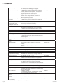
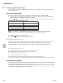
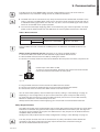
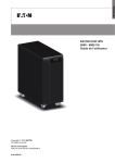
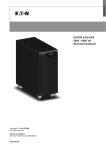
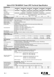
1
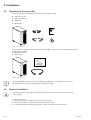
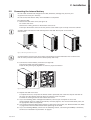
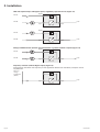
ENGLISH
EATON 9130 UPS
5000 - 6000 VA
User's guide
Copyright © 2010 EATON
All rights reserved.
Service and support:
Call your local service representative
9130 UPS-EN
Class A EMC Statements
Directives references
This UPS is classified in the C2 category according to:
EMC:
IEC 62040-2 Ed2: 2005
Safety:
IEC 62040-1: 2008 (IEC 60950-1)
Performance: IEC 62040-3: 1999
For immunity and safety tests, see Table 22 p. 33.
Emission testing level as C2 (class A) category according to CISPR 22 Ed5.2:2006 (EN 55022).
WARNING: in a residential environment, this product may cause radio interference in which case the
user may be required to take additional measures.
Requesting a Declaration of Conformity
Units that are labeled with a CE mark comply with the following harmonized standards and EU
directives:
l Harmonized Standards: IEC 61000-3-12
l EU Directives: 2006/95/EC, Council Directive on equipment designed for use within certain
voltage limits
2004/108/EC, Council Directive relating to electromagnetic compatibility
The EC Declaration of Conformity is available upon request for products with a CE mark.
For copies of the EC Declaration of Conformity, contact Eaton Power Quality or check Eaton website:
www.powerquality.eaton.com
Special Symbols
The following are examples of symbols used on the UPS or accessories to alert you to important
information:
RISK OF ELECTRIC SHOCK - Observe the warning associated with the risk of electric shock symbol.
CAUTION: REFER TO OPERATOR’S MANUAL - Refer to your operator’s manual for additional
information, such as important operating and maintenance instructions.
Do not discard the UPS or the UPS batteries in the trash.
This product contains sealed lead acid batteries and must be disposed as it's explain in this manual.
For more information, contact your local recycling/reuse or hazardous waste center.
This symbol indicates that you should not discard waste electrical or electronic equipment (WEEE) in
the trash. For proper disposal, contact your local recycling/reuse or hazardous waste center.
Information, advice, help.
Page 2
9130 UPS-EN
1. Introduction
2. Installation
2.1
2.2
2.3
2.4
2.5
2.6
2.7
2.8
Inspecting the Equipment ..............................................................................................5
Unpacking the Cabinet ....................................................................................................5
Checking the Accessory Kit.............................................................................................6
Product Installation ..........................................................................................................6
Connecting the internal battery .......................................................................................7
Connecting the EBM(s) ..................................................................................................8
Installation requirements .................................................................................................8
Installation depending on the system earthing arrangement (SEA) ................................9
3. Power cables connection & Startup
3.1
3.2
3.3
3.4
3.5
Access to terminal block ...............................................................................................11
Common input sources connection ..............................................................................11
Separate input sources connection ...............................................................................12
Frequency converter connection ...................................................................................12
UPS Initial Startup .........................................................................................................13
4. Operation
4.1
4.2
4.3
4.4
4.5
4.6
4.7
4.8
Control Panel Functions ................................................................................................14
Operating Modes...........................................................................................................17
UPS Startup and Shutdown...........................................................................................18
Transferring the UPS Between Modes .........................................................................19
Retrieving the Event Log ...............................................................................................19
Setting Power Strategy .................................................................................................19
Configuring Bypass Settings .........................................................................................19
Configuring Battery Settings .........................................................................................20
5. Communication
5.1 Installing Communication Options and Control Terminals ............................................21
5.2 Communication Options ................................................................................................21
5.3 Eaton Power Management Software Suite ..................................................................25
6. UPS Maintenance
6.1
6.2
6.3
6.4
6.5
6.6
UPS and Battery Care....................................................................................................26
Storing the UPS and Batteries ......................................................................................26
When to Replace Batteries ...........................................................................................26
Replacing Batteries........................................................................................................26
Testing New Batteries ...................................................................................................29
Recycling the Used Battery or UPS ..............................................................................30
7. Specifications
7.1 Model Specifications .....................................................................................................31
8. Troubleshooting
8.1 Typical Alarms and Conditions ......................................................................................34
8.2 Silencing the Alarm .......................................................................................................36
8.3 Service and Support ......................................................................................................36
9130 UPS-EN
Page 3
ENGLISH
Contents
1. Introduction
The Eaton® 9130 uninterruptible power system (UPS) protects your sensitive electronic equipment
from the most common power problems, including power failures, power sags, power surges,
brownouts, line noise, high voltage spikes, frequency variations, switching transients, and harmonic
distortion.
Power outages can occur when you least expect it and power quality can be erratic. These power
problems have the potential to corrupt critical data, destroy unsaved work sessions, and damage
hardware — causing hours of lost productivity and expensive repairs.
With the Eaton 9130, you can safely eliminate the effects of power disturbances and guard the integrity
of your equipment. Providing outstanding performance and reliability, the Eaton 9130’s unique benefits
include:
l True online double-conversion technology with high power density, utility frequency
independence, and generator compatibility.
l ABM® technology that uses advanced battery management to increase battery service life,
optimize recharge time, and provide a warning before the end of useful battery life.
l Selectable High Efficiency mode of operation.
l Standard communication options: one RS-232 communication port, one USB communication
port, and relay output contacts.
l Optional connectivity cards with enhanced communication capabilities.
l Extended runtime with up to four Extended Battery Modules (EBMs) per UPS.
l Firmware that is easily upgradable without a service call.
l Remote shutdown control through the Remote Power-off (RPO) port.
l Backed by worldwide agency approvals.
Figure 1. The Eaton 9130 Tower UPS and EBM (5000–6000 VA Models Shown).
Page 4
9130 UPS-EN
This section explains:
l Equipment inspection
l Unpacking the cabinet
l Checking the Accessory Kit
l Product installation
l Connecting the internal battery
l Connecting the EBM(s)
l Installation requirements
2.1
Inspecting the Equipment
If any equipment has been damaged during shipment, keep the shipping cartons and packing materials
for the carrier or place of purchase and file a claim for shipping damage. If you discover damage after
acceptance, file a claim for concealed damage.
To file a claim for shipping damage or concealed damage:
1) File with the carrier within 15 days of receipt of the equipment;
2) Send a copy of the damage claim within 15 days to your service representative.
Check the battery recharge date on the shipping carton label. If the date has passed and the
batteries were never recharged, do not use the UPS. Contact your service representative.
2.2
Unpacking the Cabinet
l Unpacking the cabinet in a low-temperature environment may cause condensation to occur
in and on the cabinet. Do not install the cabinet until the inside and outside of the cabinet are
absolutely dry (hazard of electric shock).
l The cabinet is heavy (see page 31). Use caution to unpack and move the cabinet.
Unpack the equipment and remove all the packing materials and shipping cartoon (see figure 2 for
unpacking 5000 & 6000 VA UPS and External battery cabinets).
Note! Do not lift the UPS or External Battery Cabinets from the front panel.
Figure 2. Unpacking 5000/6000 VA UPS and external battery cabinet.
Discard or recycle the packaging in a responsible manner, or store it for future use.
Place the cabinet in a protected area that has adequate airflow and is free of humidity, flammable gas,
and corrosion.
9130 UPS-EN
Page 5
ENGLISH
2. Installation
2. Installation
2.3
Checking the Accessory Kit
Verify that the following additional items are included with the UPS:
l UPS user’s guide
l Software Suite CD
l USB cable
ENGLISH
l RS232 cable
Copyright © 2009 EATON
All rights reserved.
EATON
8609 6 Forks Road
Raleigh, NC 27615 U.S.A.
Toll Free: 1.800.356.5794 or 919.872.3020
Service and support:
United States:
1-800-843-9433 or 1-919-870-3028
Canada:
1-800-461-9166 ext 260
All other countries: Call your local service representative
E-mail:
[email protected]
EATON 9130 UPS
5000 - 6000 VA
User's guide
9130 UPS-EN
Figure 3. UPS Accessory kit.
If you ordered an optional Extended Battery Module (EBM), verify that the following additional item is
included with the EBM:
l EBM user’s guide
l Power cable
Figure 4. EBM Accessory kit.
Discard the EBM user’s guide if you are installing the EBM with a new UPS at the same time.
Use the UPS user’s guide to install both the UPS and the EBM.
2.4
Product Installation
The cabinet is heavy (see page 31). Removing the cabinet from its carton requires a minimum
of two people.
To
1.
2.
3.
Page 6
install the cabinet:
Place the UPS on a flat, stable surface in its final location.
Always keep 150mm of free space behind the UPS rear panel.
If installing additional cabinets, place them next to the UPS in their final location.
9130 UPS-EN
2.5
Connecting the internal battery
Do not make unauthorized changes to the UPS; otherwise, damage may occur to your
equipment and void your warranty.
Do not connect the UPS to utility until installation is completed.
To install the UPS:
1. Remove the UPS front cover (see figure 5).
To remove the cover:
Remove the 2 fixing screws on the bottom of the cover.
Push upon the bottom of the cover and pull the cover toward you to unclip it from the cabinet.
A ribbon cable connects the LCD control panel to the UPS. Do not pull on the cable or
disconnect it.
Figure 5. Removing the UPS front cover.
A small amount of arcing may occur when connecting the internal batteries. This is normal and
will not harm personnel. Connect the cables quickly and firmly.
2. Connect the internal battery connector (see figure 6).
Connect the black connectors together.
Press the two parts tightly together to ensure a proper connection.
Figure 6. Connecting the UPS internal batteries.
3. Replace the UPS front cover.
To replace the cover, verify that the ribbon cable is protected, then insert the clips on the back of
the cover into the cabinet and push firmly to snap the cover into place.
Put back the 2 fixing screws on the bottom of the front.
4. If you are installing power management software, connect your computer to one of the
communication ports or optional connectivity card (see page 21). For the communication ports, use
an appropriate cable (not supplied).
5. If an remote power-off (disconnect) switch is required by local codes, see "Remote Power-off" (RPO)
on page 22 to install the RPO switch before powering on the UPS.
6. If you are installing EBM(s), continue to the following section, "Connecting the EBM(s)". Otherwise,
continue to "Installation requirements" on page 8.
9130 UPS-EN
Page 7
ENGLISH
2. Installation
2. Installation
2.6
Connecting the EBM(s)
To install the optional EBM(s) for a UPS:
A small amount of arcing may occur when connecting an EBM to the UPS. This is normal
and will not harm personnel. Insert the EBM cable into the UPS battery connector quickly and
firmly.
1. Plug the EBM cable(s) into the battery connector(s) as shown in figure 7. Up to four EBMs may be
connected to the UPS.
2. Verify that the EBM connections are tight and that adequate bend radius and strain relief exist for
each cable.
3. When using external battery cabinets, the number of EBMs should be set throw the LCD panel in the
"Battery settings" section, see "Configuring battery settings" on page 20.
4. Continue to "Installation requirements" on page 8.
Figure 7. Connecting the EBMs.
2.7
Installation requirements
Required protective devices and cable cross-sections
1. Recommended upstream protection (see figure 8)
Table 1. Upstream circuit breaker rating
UPS power rating
Upstream circuit breaker
5000 VA / 6000 VA
D curve – 40 A
2 poles circuit breaker
L
N
G
N
To UPS input source
and/or Bypass source.
L
Figure 8. Upstream protection.
Page 8
9130 UPS-EN
2. Required cable cross-sections
Table 2. Cable cross sections
2.8
UPS power rating
5000 VA / 6000 VA
Minimum of section
required
Terminal-block capacity
Phase and neutral solid or
stranded wire
6 mm²
AWG 10
10 mm²
AWG 8
Earthing solid or stranded
wire
6 mm²
AWG 10
10 mm²
AWG 8
Installation depending on the system earthing arrangement (SEA)
UPS with common Normal and Bypass inputs (Figure 9)
Main low
voltage
switchboard
(MLVS)
Bypass
Load
Input
Output
Change in SEA between upstream and downstream or galvanic isolation required (Figure 10)
Main low
voltage
switchboard
(MLVS)
Bypass
Load
Input
Output
UPS with separate Normal and Bypass inputs (Figure 11)
Main low
voltage
switchboard
(MLVS)
Bypass
Load
Input
Output
Change in SEA between upstream and downstream or galvanic isolation required (Figure 12)
Bypass
Main low
voltage
switchboard
(MLVS)
Load
Input
*
9130 UPS-EN
Output
The transformer is not necessary if:
l Normal and Bypass inputs are connected to the same source,
l and wires cross sections and wires lengths on Input and Bypass inputs are identical,
l and upstream protection is provided by only one switch with RCD (residual current
device) for Input and Bypass inputs.
Page 9
ENGLISH
2. Installation
2. Installation
UPS with separate Input and Bypass inputs, supplied by separate sources (Figure 13)
Bypass
MLVS1
MLVS2
Load
Input
Output
Bypass
MLVS1
MLVS2
Load
Output
Input
Change in SEA between upstream and downstream or galvanic isolation required (Figure 14)
Bypass
MLVS1
11
MLVS2
10
Input
Load
8
Output
Frequency converter (without Bypass input) (Figure 15)
Configuration used when the frequency of the application differs from the Mains, example: marine
requirements.
Main low
voltage
switchboard
(MLVS)
Load
Input
Page 10
Output
9130 UPS-EN
This section explains:
l Access to terminal block
l Common input sources connection
l Separate input sources connection
l Frequency converter connection
l UPS Initial startup
3.1
Access to terminal block
1. Access to terminal block: remove the 4 screws of the terminal block cover (see figure 16)
Figure 16. Access to terminal block.
l High leakage current:
Earth connection essential before connecting supply.
3.2
Common input sources connection
This type of connection must be carried out by qualified electrical personnel
Before carrying out any connection, check that the upstream protection device Input source is
open ("O") (OFF).
Always connect the earthing wire first.
BYPASS
JP L
N
INPUT
L
N
OUTPUT
L
N
1 - Make sure the metal jumper is connected
(see figure 17).
2 - Insert the Input source cable through the cable
gland.
3 - Connect the 3 cables to the Input source terminal
block.
4 - Insert the Output cable through the cable gland.
5 - Connect the 3 cables to the output terminal
block.
Figure 17.
6 - Put back and secure the terminal block cover
with the 4 screws.
7 - Tightened the cable glands.
9130 UPS-EN
Page 11
ENGLISH
3. Power cables connection & Startup
3. Power cables connection & Startup
3.3
Separate input sources connection
This type of connection must be carried out by qualified electrical personnel.
Before carrying out any connection, check that the upstream protection device Input source is
open ("O") (OFF).
Always connect the earthing wire first.
BYPASS
JP L
N
INPUT
L
N
OUTPUT
L
N
1 - Remove the metal jumper (see figure 18).
2 - Insert the Input source cable through the cable
gland.
3 - Connect the 3 cables to the Input terminal block.
4 - Insert the Bypass source cable through the cable
gland.
5 - Connect the 3 cables to the Bypass terminal
block.
6 - Insert the Output cable through the cable gland.
7 - Connect the 3 cables to the output terminal
block.
Figure 18.
8 - Put back and secure the terminal block cover
with the 2 screws.
9 - Tightened the cable glands.
3.4
Frequency converter connection
This type of connection must be carried out by qualified electrical personnel.
Before carrying out any connection, check that the upstream protection device Input source is
open ("O") (OFF).
Always connect the earthing wire first.
BYPASS
JP L
N
INPUT
L
N
OUTPUT
L
N
1 - Remove the metal jumper (see figure 19).
2 - Insert the Input source cable through the cable
gland.
Do not connect anything to the Bypass
terminal block.
3 - Connect the 3 cables to the Input terminal block.
4 - Insert the Output cable through the cable gland.
5 - Connect the 3 cables to the output terminal
block.
Figure 19.
6 - Put back and secure the terminal block cover
with the 2 screws.
7 - Tightened the cable glands.
Page 12
9130 UPS-EN
3.5
UPS Initial Startup
To start up the UPS:
Verify that the total equipment ratings do not exceed the UPS capacity to prevent an overload
alarm.
1. Verify that the internal batteries are connected.
See "Connecting the internal battery" on page 7.
2. If optional EBMs are installed, verify that the EBMs are connected to the UPS.
See "Connecting the EBM(s)" on page 8.
3. Set the upstream circuit breaker (not included) to the "I" position (ON).
The UPS front panel display illuminates and shows a status of "UPS initializing..."
4. Verify that the UPS transfers to Standby mode ("UPS on standby").
5. Press the
button on the UPS front panel for at least one second.
The UPS front panel display changes status to "UPS starting..."
6. Check the UPS front panel display for active alarms or notices. Resolve any active alarms before
continuing. See "Troubleshooting" on page 34.
If the
indicator is on, do not proceed until all alarms are clear. Check the UPS status from the
front panel to view the active alarms. Correct the alarms and restart if necessary.
7. Verify that the
indicator illuminates solid, indicating that the UPS is operating normally and any
loads are powered.
The UPS should be in Normal mode.
8. Press the ESC button until the start screen appears.
9. If optional EBMs are installed, see "Configuring the UPS for EBMs" on page 20 to set the number of
installed EBMs.
10. To change any other factory-set defaults, see "Operation" on page 14.
If you are powering RCD type loads, with high inrush current, it is possible to first start on
bypass:
1. In standby mode, enable the user setting “Start on Bypass” (disabled by default).
2. Press the on button to start the UPS. The UPS will start on Bypass for 5~15 seconds, and then
transfer automatically to Normal mode.
Eaton recommends setting the date and time.
At initial startup, the UPS sets system frequency according to input line frequency (input
frequency auto-sensing is enabled by default). After initial startup, auto-sensing is disabled
until manually re-enabled by output frequency setting.
At initial startup, input voltage auto-sensing is disabled by default. When manually enabled
by output voltage setting, at the next AC startup the UPS sets output voltage according to
input line voltage. After the subsequent startup, auto-sensing is disabled until manually
re-enabled by output voltage setting.
11. If you installed an optional RPO, test the RPO function:
Activate the external RPO switch. Verify the status change on the UPS display.
Deactivate the external RPO switch and restart the UPS.
The internal batteries charge to 90 % capacity in less than 3 hours. However, Eaton
recommends that the batteries charge for 48 hours after installation or long-term storage. If
optional EBMs are installed, see the recharge times listed in table 24 on page 33.
9130 UPS-EN
Page 13
ENGLISH
3. Power cables connection & Startup
4. Operation
This chapter contains information on how to use the Eaton 9130, including front panel operation,
operating modes, UPS startup and shutdown, transferring the UPS between modes, retrieving the
Event Log, setting the power strategy, and configuring bypass settings, load segments, and battery
settings.
4.1
Control Panel Functions
The UPS has a four-button graphical LCD with backlight. It provides useful information about the UPS
itself, load status, events, measurements, and settings (see figure 20).
Power On Indicator (green)
On Battery Indicator (yellow)
Bypass Indicator (yellow)
Alarm Indicator (red)
esc
Escape
Up
Down
Enter
On/Off Button
Figure 20. Eaton 9130 Control Panel.
The
button controls only the UPS output. The
connected to the UPS.
button has no effect on equipment
Table 3 shows the indicator status and description.
Table 3 - Indicator Descriptions
Indicator
Status
On
Green
Flashing
On
Description
The UPS is operating normally on bypass during High Efficiency
operation.
A new information message is active.
The UPS is in Battery mode.
Yellow
Flashing
On
The battery voltage is below the warning level.
The UPS is in Bypass mode.
On
The UPS has an active alarm or fault. See "Troubleshooting" on
page 33 for additional information.
Yellow
Red
Changing the Language
Press and hold the first button on the left for approximately three seconds to select the language menu.
This action is possible from any LCD menu screen.
Display Functions
As the default or after 15 minutes of inactivity, the LCD displays the start screen.
The backlit LCD automatically dims after 15 minutes of inactivity. Press any button to restore the
screen.
Press any button to activate the menu options. Use the two middle buttons ( and ) to scroll through
the menu structure. Press the Enter (
) button to select an option. Press the ESC button to cancel or
return to the previous menu.
Page 14
9130 UPS-EN
The table 4 shows the basic menu structure.
Table 4. Menu Map for Display Functions
Main Menu
Submenu
UPS Status
Event Log
Measurements
Control
Go to Bypass
Start Battery Test
Reset Error State
Restore Factory Settings
Identification
Settings
User Settings
Service Settings
Display Information or Menu Function
Main status (mode and load) / Notice or Alarm status
(if any) / Battery status (state and charge level)
Displays up to 127 events and alarms.
The Event Log is also available through the serial port. See
"Retrieving the Event Log" on page 19.
Load W VA / Load A pf / Output V Hz / Input V Hz / Bypass V Hz /
Input Line Events / Battery V min
Transfers the UPS system to internal Bypass mode.
When this command is active, the option changes to "Go to
Normal".
Starts a manual battery test.
See "Testing New Batteries" on page 29.
Clears a "Battery Test Failed" alarm
Returns all settings to original values
UPS Type / Part Number / Serial Number / Firmware
See Table 5 for details.
This menu is password-protected.
User Settings
The following table displays the options that can be changed by the user.
Table 5. User Settings
Description
Available Settings
Default Setting
Change Language
[English] [French] [Spanish] [German] [Russian]
Menus, status, notices, and alarms are in all
supported languages. UPS faults, Event Log data,
and settings are in English only.
[Enabled] [Disabled]
If Enabled is selected, the password is USER.
[Enabled] [Disabled]
Set Year, Month, Day, Hours, Minutes
Date: yyyy/mm/dd
Time: hh:mm
Setup: [Not Used] [Force Bypass] [Remote
Shutdown] [Delayed Shutdown]
[On Generator] [Building Alarm 1]
Active: [High] [Low]
See "Programmable Signal Inputs" on page 24.
[UPS ok] [On Bypass] [On Battery] [Battery Low]
[Ext. Charger On]
See "Relay Output Contacts" on page 23.
English
User Password
Audible Alarms
Set Date and Time
NOTE: time is a 24-hour
clock.
Signal Inputs
Relay Configuration
Serial Port Configuration
Control Commands from
Serial Port
Output Voltage
Output Frequency
Frequency Converter
Overload Alarm Level
Transfer to Bypass When
Overload*
9130 UPS-EN
[1200 bps] [2400 bps] [9600 bps]
NOTE: USB communication requires 9600 bps.
[Enabled] [Disabled]
[208V] [220V] [230V] [240V] [Autosensing]
[50Hz] [60Hz] [Autosensing]
[Enabled] [Disabled]
If Enabled, the UPS operates as a frequency
converter, with bypass operation and all bypassrelated alarms disabled.
[10%] [20%] [30%] ... [100%]
These values affect alarm level only, not UPS
operation such as transfers or shutdown.
[Immediate] [After Delay]
If Immediate, transfer occurs at load > 102 %.
If After Delay, transfer occurs according to table 20
on page 32.
Disabled
Enabled
2008/01/01
12:00
RS232-3: Not Used, High
cXSlot Serial: Delayed
Shutdown, High
cXSlot Signal: Remote
Shutdown, Low
Standard: UPS ok
RS232-1: Battery Low
RS232-8: On Battery
cXSlot-K1: On Battery
cXSlot-K2: Battery Low
cXSlot-K3: UPS ok
cXSlot-K4: On Bypass
RS232: 9600 bps
cXSlot: 9600 bps
RS232: Enabled
cXSlot: Enabled
230 V
Autosensing
Disabled
100 %
Generates the Output.
Overload alarm at the set
level.
After Delay
Page 15
ENGLISH
4. Operation
4. Operation
Power Strategy
Automatic start delay
Automatic on battery
shutdown
Start on Battery
NOTE: utility must be
present and output
enabled at initial UPS
startup.
Energy Saving Mode
Remote Shutdown Delay
Delayed Shutdown Delay
On Battery Notice Delay
Site Wiring Fault Alarm
Bypass Voltage Low
Limit*
Bypass Voltage High
Limit*
Qualify Bypass*
[Normal] [High Efficiency]
See "Setting Power Strategy" on page 19.
[No Delay] [Disabled] [1,2,...,32767 s]
To define if the load turns automatically on, with
the delay set after the utility return, if it has been
shutdown by:
- signal input with auto-restart option
- an XCP command with autorestart option
- battery under voltage state, or automatic on
battery shutdown command.
[Disabled] [No Delay] [1,2,...,32767 s]
To define if the load turns automatically off when
"UPS on battery" state activates.
[Enabled] [Disabled]
After initial startup, battery voltage must exceed
2.10 volts per cell to start on battery.
Normal
[Disabled] [50W] [100W] ... [1000W]
UPS output is turned off (after 5 min) if the UPS is
on battery and output power is below the selected
level.
[No Delay] [1s] [2s]...[10800s]
[No Delay] [1s] [2s]...[10800s]
[0] [1s] [2s]...[99s]
[Enabled] [Disabled]
An active site wiring fault alarm prevents startup or,
if operating, forces operation to Battery mode and
disables bypass.
[-4%] [-5%] ... [-20%] of nominal
Disabled
[+4%] [+5%] ... [+20%] of nominal
+10 % of nominal
[Never] [When in Spec] [Always on UPS Fault]
[Always]
Synchronization Window* [Sync Disabled] [±0.5 Hz] [±1.0 Hz] [±2.0 Hz]
[±3.0 Hz]
Unsynchronized
[Enabled] [Disabled]
Transfers*
Number of Battery Strings [0] [1] [2] ... [10]
See "Configuring the UPS for EBMs" on page 18.
Battery Charge Mode
[ABM Cycling] [Constant]
Temperature
[Enabled] [Disabled]
Compensated Charging
If Disabled, the default charger voltages for 25 °C
(77°F) are assumed.
Battery Charge % to
[Not Checked] [10] [20] ... [100]
Restart
If a percentage is selected, automatic restart (if
enabled) occurs when the battery’s charge reaches
the selected level.
Battery Low Alarm
[Immediate] [2 min] [3 min] [5 min]
The "Battery Low" alarm triggers when the set
amount of backup time (approximately) remains in
the batteries. If set to Immediate, the alarm activates
at the same time as the "UPS on Battery" notice.
Automatic Battery Support [Enabled] [Disabled]
Tests
See "Running Automatic Battery Tests" on page 20
Deep discharge protection [Enabled] [Disabled]
Protection against deep discharge. If disabled, Eaton
warranty will be void.
Start on Bypass
[Disabled] [Enabled]
During start up sequence, transfer first on Bypass
(for 5~15 seconds) then transfer online.
Ambient Temperature
[Enabled] [Disabled]
Warning
Predictive Maintenance
[Enabled] [Disabled]
Notices
Remote Power-off (RPO)
[Open] [Closed]
Input Polarity
No Delay
Disabled
Enabled
No Delay
120 s
5s
Enabled
-15 % of nominal
When in Spec
±3 Hz
Enabled
1
ABM Cycling
Enabled
Not Checked
3 min
Enabled
Enabled
Disabled
Enabled
Enabled
Open
* See "Configuring Bypass Settings" on page 19.
Page 16
9130 UPS-EN
4.2
Operating Modes
The Eaton 9130 front panel indicates the UPS status through the UPS indicators (see figure 20 on page
14).
Normal Mode
During Normal mode, the
indicator illuminates solid and the UPS is powered from the utility.
The UPS monitors and charges the batteries as needed and provides filtered power protection to your
equipment.
The UPS may at times silently implement a High Alert mode, usually when incoming utility conditions
are unfavorable. In High Alert mode, the UPS disables the battery support test to ensure maximum
capacity from the batteries if needed. The UPS will remain in High Alert for 24 hours or until changed
by a Power Strategy command before returning to its previous mode.
Optional High Efficiency and Energy Saving settings minimize heat contribution to the rack
environment. See "User Settings" on page 15.
Battery Mode
When the UPS is operating during a power outage, the alarm beeps once every five seconds and the
indicator illuminates solid.
When the utility power returns, the UPS transfers to Normal mode operation while the battery
recharges.
If battery capacity becomes low while in Battery mode, the
indicator flashes slowly and the audible
indicator also illuminates
alarm beeps once every second. If the "Battery Low" alarm is set, the
solid. This warning is approximate, and the actual time to shutdown may vary significantly.
Depending on the UPS load and the number of Extended Battery Modules (EBMs) connected,
the "Battery Low" warning may occur before the batteries reach 25 % capacity. See table 23 on
page 33 for estimated runtimes.
When utility power is restored after the UPS shuts down, the UPS automatically restarts.
Bypass Mode
In the event of a UPS overload or internal failure, the UPS transfers your equipment to utility power.
Battery mode is not available and your equipment is not protected; however, the utility power
continues to be passively filtered by the UPS. The
indicator illuminates.
The UPS remains in Bypass mode for at least 5 seconds (if the bypass source remains acceptable). If
three transfers to Bypass occur within 10 minutes for any reason other than user command, the UPS
locks in Bypass for 1 hour or until any control button is pressed.
The UPS transfers to Bypass mode when:
l the user activates Bypass mode through the front panel.
l the UPS detects an internal failure.
l the UPS has an overtemperature condition.
l the UPS has an overload condition listed in table 20 on page 32.
The UPS shuts down after a specified delay for overload conditions listed in table 20 on page 32.
The UPS remains on to alarm the fault
Standby Mode
When the UPS is turned off and remains plugged into a power outlet, the UPS is in Standby mode.
The
indicator is off, indicating that power is not available to your equipment. The battery recharges
when necessary, and the communication bay is powered.
If utility fails and output turns off due to drained batteries or UPS internal failure, the UPS alarms in
Standby mode and powers the communication bay for 1 hour 30 minutes or until battery voltage drops
below 1.75 volts per cell (whichever occurs first).
If utility fails while the UPS is in Standby mode, the logic power supply turns off in approximately
10 seconds.
If the UPS is waiting on commands and utility fails, unit and logic power turn off in approximately
30 seconds.
9130 UPS-EN
Page 17
ENGLISH
4. Operation
4. Operation
4.3
UPS Startup and Shutdown
To
l
l
l
start up or shut down the UPS, see:
"Starting the UPS" on page 18
"Starting the UPS on Battery" on page 18
"UPS Shutdown" on page 18
Starting the UPS
"Start on Bypass" settings can be used to power on capacitive loads.
To start the UPS:
1. Verify that the UPS power cord is plugged in.
2. Switch on utility power where the UPS is connected.
The UPS front panel display illuminates and shows a status of "UPS initializing...".
3. Verify that the UPS transfers to Standby mode ("UPS on standby").
4. Press the
button on the UPS front panel for at least one second.
The UPS front panel display changes status to "UPS starting...".
5. Check the UPS front panel display for active alarms or notices. Resolve any active alarms before
continuing. See "Troubleshooting" on page 34.
If the
indicator is on, do not proceed until all alarms are clear. Check the UPS status from the
front panel to view the active alarms. Correct the alarms and restart if necessary.
6. Verify that the
indicator illuminates solid, indicating that the UPS is operating normally and any
loads are powered.
The UPS should be in Normal mode.
7. Press the ESC button until the start screen appears.
Starting the UPS on Battery
Before using this feature, the UPS must have been powered by utility power with output enabled
at least once.
Battery start can be disabled. See the "Start on Battery" setting in "User Settings" on page 16.
To start the UPS on battery:
1. Press the
button on the UPS front panel until the UPS front panel display illuminates and shows
a status of "UPS starting...".
indicator illuminates solid. The
The UPS cycles through Standby mode to Battery mode. The
UPS supplies power to your equipment.
2. Check the UPS front panel display for active alarms or notices besides the "UPS on Battery" notice
and notices that indicate missing utility power. Resolve any active alarms before continuing. See
"Troubleshooting" on page 34.
Check the UPS status from the front panel to view the active alarms. Correct the alarms and restart
if necessary.
3. Press the ESC button until the start screen appears.
UPS Shutdown
To shut down the UPS:
1. Press the
button on the front panel for three seconds.
The UPS starts to beep and shows a status of "UPS off pending...". The UPS then transfers to
Standby mode, and the
indicator turns off.
Releasing the
button before three seconds returns the UPS to its original operating mode.
2. Switch off utility power where the UPS is connected.
4.4
Transferring the UPS Between Modes
From Normal to Bypass Mode. Press any button to activate the menu options, then select CONTROL
and GO TO BYPASS.
From Bypass to Normal Mode. Press any button to activate the menu options, then select CONTROL
and GO TO NORMAL.
Page 18
9130 UPS-EN
4.5
Retrieving the Event Log
To retrieve the Event Log through the display:
1. Press any button to activate the menu options, then select EVENT LOG.
2. Scroll through the listed events.
To retrieve the Event Log through the serial port:
1. From the communication device connected to the serial port, send one of the following command
sequences: ESC-L (ASCII characters 27 and 76) or ESC-I (ASCII characters 27 and 108).
The UPS returns a header containing the UPS identification (UPS type, part number, and serial
number), firmware version, and the current date and time, followed by the event history.
2. Use the connected communication device to view or print the information. The report is delivered in
ASCII format.
4.6
Setting Power Strategy
On the High Efficiency setting, the UPS operates normally on Bypass, transfers to inverter in less than
10 ms when utility fails, and transfers back to Bypass in 1 minute after utility returns.
High Efficiency operation is available after one minute of stable power.
To set the power strategy:
1. Press any button to activate the menu options, then select SETTINGS, USER SETTINGS, and POWER
STRATEGY.
2. Select HIGH EFFICIENCY or NORMAL, and ENTER to confirm.
4.7
Configuring Bypass Settings
The following settings are available for configuring Bypass operation.
Transfer to Bypass When Overload. The default forces a transfer to Bypass when any overload
condition occurs. You can configure the setting for a delayed transfer, with the amount of delay
determined by the amount of overload, as shown in table 20 on page 32.
Bypass Voltage Low Limit. The default disables a transfer to Bypass if the measured bypass voltage
level is below the nominal output voltage minus 15 %. You can configure the setting for another
percentage of nominal. This setting can be overruled by the "Qualify Bypass" setting.
Bypass Voltage High Limit. The default disables a transfer to Bypass if the measured bypass voltage
level is above the nominal output voltage plus 10 %. You can configure the setting for another
percentage of nominal. This setting can be overruled by the "Qualify Bypass" setting.
Qualify Bypass. The default allows a transfer to Bypass only when Bypass is within the following
specifications:
l Bypass voltage is between the "Bypass Voltage Low Limit" and "Bypass Voltage High Limit"
settings.
l Bypass frequency is within nominal frequency ±3 Hz.
l the inverter is synchronized with Bypass when the "Unsynchronized Transfers" setting is
disabled.
You can prohibit Bypass ("Never") or always allow Bypass with no specification checking ("Always").
For "Always on UPS Fault", transfer to Bypass is always made on UPS fault; otherwise, operation
proceeds as with the default setting.
Synchronization Window. The UPS tries to synchronize with Bypass when the Bypass frequency is less
than the value set for the "Synchronization Window" setting. When the Bypass frequency is more than
the set value, the UPS goes to nominal frequency. On Bypass the synchronization window is ±3 Hz. If
synchronization is disabled ("Sync Disabled"), the UPS will synchronize only when operating on Bypass.
Unsynchronized Transfers. The default allows an unsynchronized transfer to Bypass. You can configure
the setting to not allow such transfers. This setting can be overruled by the "Qualify Bypass" setting.
9130 UPS-EN
Page 19
ENGLISH
4. Operation
4. Operation
4.8
Configuring Battery Settings
Set the UPS for the number of EBMs installed whether to run automatic battery tests, and automatic
restart configuration.
Configuring the UPS for EBMs
To ensure maximum battery runtime, configure the UPS for the correct number of EBMs:
1. Press any button on the front panel display to activate the menu options, then select SETTINGS,
USER SETTINGS, and NUMBER OF BATTERY STRINGS.
2. Use the
or
buttons to select the number of battery strings according to your UPS configuration:
Table 6. EBM vs number of Battery strings
All UPS and EBM Cabinets
Number of Battery Strings
UPS only (internal batteries)
1 (default)
UPS + 1 EBM
3
UPS + 2 EBMs
5
UPS + 3 EBMs
7
UPS + 4 EBMs
9
NOTE: if 0 is selected, no batteries are connected and all battery-related alarms are disabled.
NOTE: the UPS contains one battery string; each EBM contains two battery strings.
3. Press the
4. Press the
ESC
button to save the setting.
button until the start screen appears.
Running Automatic Battery Tests
Automatic battery tests run approximately every 30 days, unless disabled. During the test, the UPS
transfers to Battery mode and discharges the batteries for 25 seconds under the existing load.
The "UPS on Battery" notice and the "Battery Low" alarm do not activate during a battery test.
For automatic battery tests to run:
l the "Automatic Battery Support Tests" setting must be enabled.
l the UPS must be in Normal mode, with no active alarms.
l the batteries must be fully charged.
l the bypass voltage must be acceptable.
l no manual battery test was initiated previously in the same charging cycle.
To pass the battery test, the battery voltage must remain above the threshold value during discharge.
Configuring Automatic Restart
The UPS automatically restarts if utility returns after the output was shut off due to exhausted batteries,
a shutdown input signal, or automatic shutdown command.
You can set the load segment for the amount of time to delay the restart once utility returns, using the
"Automatic Start Delay" setting. You can also configure UPS restart to depend on the battery charge
level, using the "Battery Charge % to Restart" setting.
Page 20
9130 UPS-EN
This section describes the:
l Communication ports (RS-232 and USB)
l Connectivity cards
l Remote Power-off (RPO)
l Relay output contacts
l Programmable signal inputs
l Modem operation
l EATON® Power Management Software
Relay output
RPO
USB
RS232
Interface Com
External battery
(EBM)
Figure 21. Communication Options and Control Terminals.
5.1
Installing Communication Options and Control Terminals
To install the communication options and control terminals:
1. Install the appropriate connectivity card and/or necessary cable(s) and connect the cables to the
appropriate location.
See Figure 21 and the following section, "Communication Options", for detailed information.
2. Route and tie the cable(s) out of the way.
3. Continue to "Operation" on page 14 to start up the UPS.
5.2
Communication Options
The Eaton 9130 has serial communication capabilities through the USB and RS-232 communication
ports or through a connectivity card in the available communication bay.
The UPS supports two serial communication devices according to the following table 7:
Independent
Communication Bay
Any connectivity card
Any connectivity card
Multiplexed
USB
Available
Not in use
RS-232
Not in use
Available
You can configure relays, signal inputs, and the serial port baud rate through the front panel
menus (see table 4 on page 15).
The communication speed of the USB port is fixed at 9600 bps.
9130 UPS-EN
Page 21
ENGLISH
5. Communication
5. Communication
RS 232 and USB Communication Ports
To establish communication between the UPS and a computer, connect your computer to one of
the UPS communication ports using an appropriate communication cable. See Figure 21 for the
communication port locations.
When the communication cable is installed, power management software can exchange data with the
UPS. The software polls the UPS for detailed information on the status of the power environment. If a
power emergency occurs, the software initiates the saving of all data and an orderly shutdown of the
equipment.
The cable pins for the RS 232 communication port are identified in figure 22, and the pin functions are
described in Table 8.
5
4
9
3
8
2
7
1
6
Figure 22. RS 232 Communication Port (DB-9 Connector).
Table 8. RS 232 Communication Port Pin Assignment
Pin Number
1
2
3
4
5
6
7
8
9
Signal Name
DCD
RxD
TxD
DTR
GND
DSR
RTS
CTS
RI
Function
Battery Low signal (1)(3)
Transmit to external device
Receive from external device (2)
PnP from external device (tied to Pin 6)
Signal common (tied to chassis)
To external device (tied to Pin 4)
No connection
On Battery signal (1)(3)
+8-12 Vdc power
Direction from the UPS
Out
Out
In
In
—
Out
In
Out
Out
(1) Configurable; see the "Relay Configuration" setting in "User Settings" on page 15.
(2) If Pin 3 receives a Low (+V) signal for ≥ 5 seconds, the UPS executes the command selected by the "Signal Inputs" setting in "User
Settings" on page 15.
(3) When the selected condition is active, output signals on Pins 1 and 8 shift from Low (positive voltage) to High (negative voltage). When
the condition no longer exists, the output signal returns to Low.
Connectivity Cards
Connectivity cards allow the UPS to communicate in a variety of networking environments and with
different types of devices. The Eaton 9130 has one available communication bay for the following
connectivity cards:
l Connect UPS-MS Web/SNMP Card - has SNMP and HTTP capabilities as well as monitoring
through a Web browser interface; connects to Ethernet network. In addition, a Environmental
Monitoring Probe can be attached to obtain humidity, temperature, smoke alarm, and security
information.
l Relay Interface Card - has isolated dry contact (Form-C) relay outputs for UPS status: Utility
failure, Low battery, UPS alarm/OK, or On bypass.
See figure 21 on page 21 for the location of the communication bay.
ETHERNET
Setting/Sensor
ConnectUPS-MS Web/SNMP Card
Relay Interface Card
100M
10M
UPS data
Reset
Figure 23. Optional Connectivity Cards.
Remote Power-off
RPO is used to shut down the UPS from a distance. This feature can be used for shutting down the
load and the UPS by thermal relay, for instance in the event of room over temperature. When RPO is
activated, the UPS shuts down the output and all its power converters immediately. The UPS remains
on to alarm the fault.
Page 22
9130 UPS-EN
The RPO circuit is an IEC 60950 safety extra low voltage (SELV) circuit. This circuit must be
separated from any hazardous voltage circuits by reinforced insulation.
l The RPO must not be connected to any utility connected circuits. Reinforced insulation to the
utility is required. The RPO switch must have a minimum rating of 24 Vdc and 20 mA and be
a dedicated latching-type switch not tied into any other circuit. The RPO signal must remain
active for at least 250 ms for proper operation.
l To ensure the UPS stops supplying power to the load during any mode of operation, the input
power must be disconnected from the UPS when the remote power-off function is activated.
Table 9. RPO connections
RPO Connections
Wire Function
RPO
L1
L2
Terminal Wire Size Rating
Suggested Wire Size
4–0.32 mm² (12–22 AWG)
0.82 mm² (18 AWG)
Leave the RPO connector installed in the RPO port on the UPS even if the RPO function is not
needed.
Remote control connection and test (see figure 21 on page 21 for RPO location.)
1 - Check the UPS is shut down and the electrical supply network disconnected.
2 - Remove RPO connector from the UPS by unfitting the screws.
3 - Connect a normally closed volt-free contact between the two pins of connector, see picture 24.
Contact open: shut down of UPS
To return to normal operation, deactivate the external remote shut down
contact and restart the UPS from the front panel.
RPO
+ -
Polarity
Figure 24.
4 - Plug the RPO connector into the back of the UPS and fix the screws.
5 - Connect and restart the UPS according to the previously described procedures.
6 - Activate the external remote shut down contact to test the function.
You can set the RPO polarity. See the "RPO Input Polarity" setting in "User Settings" on page 15.
Depending on user configuration, the pins must be shorted or open to keep the UPS running.
To restart the UPS, reconnect (re-open) the RPO connector pins and turn on the UPS manually.
Maximum resistance in the shorted loop is 10 ohm.
Always test the RPO function before applying your critical load to avoid accidental load loss.
Relay Output Contacts
The UPS incorporates three programmable relay outputs with potential free contacts for remote alarm
indications: a standard relay port and two outputs in the RS 232 communication port. See figure 21
on page 21 for the locations of the ports. An additional four relay outputs can be obtained with the
compatible Relay Interface Card.
Configure the relay outputs with the "Relay Configuration" setting in "User Settings" on page 15.
The relay output contacts must not be connected to any utility connected circuits. Reinforced
insulation to the utility is required. The relay output contacts have a maximum rating of
30 Vac/1A and 60 Vdc/2A nominal values.
9130 UPS-EN
Page 23
ENGLISH
5. Communication
5. Communication
The table 10 shows the options for the relay output contacts.
Table 10. Relay Output Configuration Options
Relay Signal
Description
UPS ok
Activated when the UPS is feeding the load on inverter or on bypass and no
alarms are active
On Bypass
Activated when the UPS is NOT on bypass operation
On Battery
Activated when the UPS operates on battery and the "On Battery Notice
Delay" time has expired
Battery Low
Activated with the "Battery Low" alarm according to the "Battery Low Alarm"
setting
Ext. Charger On
Controls an optional external battery charger on and off
The figure 25 shows the connection of the relay output contacts.
Common
Normally closed
Normally open
1 2 3
Figure 25. Standard Relay Port Connections.
The figure 26 shows an example where a lamp is connected on the relay output contacts.
Relay signal
G
G
L1
L2
True
Not true
1
Normally
open
3
Common
2 3
Normally Common
closed
G : external power supply
Figure 26. Example of Standard Relay Port Connections with lamp.
Programmable Signal Inputs
The UPS incorporates four programmable signal inputs: one RS 232 input, two connectivity card inputs,
and one RPO terminal input. See figure 21 on page 21 for the locations of the ports. Configure the
inputs with the "Signal Inputs" setting in "User Settings" on page 15.
The table 11 shows the programmable settings for the signal inputs. Table 12 shows the operation logic
for the signal inputs.
Table 11. Programmable Signal Inputs
Signal
Page 24
Description
Not Used
The input operates only as a serial input (RxD) or has no function.
Force Bypass
If active, the UPS is forced to static bypass operation regardless of the bypass
status.
Remote
Shutdown
If active, the UPS output turns off after a user-defined remote shutdown delay.
The batteries continue charging. Inactive input does not abort the shutdown
countdown and does not cause the UPS to start up automatically.
Delayed
Shutdown
(and restart)
If active, the UPS output turns off after a user-defined delayed shutdown delay.
The batteries continue charging. Inactive input does not abort the shutdown
countdown but will cause the UPS to start up automatically if the input voltage
exists.
On Generator
If active, synchronization is disabled and the UPS transfers to bypass.
Building Alarm 1
If active, the UPS generates the "Building Alarm 1" alarm.
9130 UPS-EN
Table 12. Polarity Options
Input
High
Low
5.3
Description
Active state on high voltage (+Udc) level
Active state on low voltage (GND or -Udc) level
Eaton Power Management Software Suite
Each Eaton 9130 UPS ships with Eaton Power Management Software Suite. To begin installing, see the
instructions accompanying the Software Suite CD.
When installing software, select serial port installation. For the UPS manufacturer and model,
select Eaton and Eaton 9130. If the Eaton brand options are not available in your version of the
software, select Generic UPSs for the manufacturer and Generic XCP for the model.
Eaton software suite provides up-to-date graphics of UPS power and system data and power flow.
It also gives you a complete record of critical power events, and it notifies you of important UPS or
power information.
If there is a power outage and the Eaton 9130 UPS battery power becomes low, Eaton Sofwtare suite
can automatically shut down your computer system to protect your data before the UPS shutdown
occurs.
9130 UPS-EN
Page 25
ENGLISH
5. Communication
6. UPS Maintenance
This section explains how to:
l Care for the UPS and batteries
l Replace the UPS internal batteries and Extended Battery Modules (EBMs)
l Test new batteries
l Recycle used batteries or UPS
6.1
UPS and Battery Care
For the best preventive maintenance, keep the area around the UPS clean and dust free. If the
atmosphere is very dusty, clean the outside of the system with a vacuum cleaner.
For full battery life, keep the UPS at an ambient temperature of 25 °C (77 °F).
If the UPS requires any type of transportation, verify that the UPS is disconnected and turned off
and then disconnect the UPS internal battery connector (see figure 28 on page 28).
The batteries in the UPS are rated for a 3–5 year service life. The length of service life varies,
depending on the frequency of usage and ambient temperature. Batteries used beyond expected
service life will often have severely reduced runtimes. Replace batteries at least every 5 years to
keep units running at peak efficiency.
6.2
Storing the UPS and Batteries
If you store the UPS for a long period, recharge the battery every 6 months by connecting the UPS
to utility power. The internal batteries charge to 90 % capacity in less than 3 hours. However, Eaton
recommends that the batteries charge for 48 hours after long-term storage. If optional EBMs are
installed, see the recharge times listed in table 24 on page 33.
Check the battery recharge date on the shipping carton label. If the date has passed and the batteries
were never recharged, do not use the UPS. Contact your service representative.
6.3
When to Replace Batteries
When the
indicator illuminates, the audible alarm beeps, and the "Battery Needs Service" alarm
displays, the batteries may need replacing. Contact your service representative to order new batteries.
6.4
Replacing Batteries
DO NOT DISCONNECT the batteries while the UPS is in Battery mode.
Batteries can be replaced easily without turning the UPS off or disconnecting the load.
If you prefer to remove input power to change the batteries, see "UPS Shutdown" on page 18.
Consider all warnings, cautions, and notes before replacing batteries.
Page 26
9130 UPS-EN
l Servicing should be performed by qualified service personnel knowledgeable of batteries and
required precautions. Keep unauthorized personnel away from batteries.
l Batteries can present a risk of electrical shock or burn from high short circuit current. Observe
the following precautions: 1) Remove watches, rings, or other metal objects; 2) Use tools with
insulated handles; 3) Do not lay tools or metal parts on top of batteries, 4) Wear rubber gloves
and boots.
l When replacing batteries, replace with the same type and number of batteries or battery packs.
Contact your service representative to order new batteries.
l Proper disposal of batteries is required. Refer to your local codes for disposal requirements.
l Never dispose of batteries in a fire. Batteries may explode when exposed to flame.
l Do not open or mutilate the battery or batteries. Released electrolyte is harmful to the skin and
eyes and may be extremely toxic.
l Determine if the battery is inadvertently grounded. If inadvertently grounded, remove source
from ground. Contact with any part of a grounded battery can result in electrical shock. The
likelihood of such shock can be reduced if such grounds are removed during installation and
maintenance (applicable to equipment and remote battery supplies not having a grounded
supply circuit).
l ELECTRIC ENERGY HAZARD. Do not attempt to alter any battery wiring or connectors.
Attempting to alter wiring can cause injury.
l Disconnect charging source prior to connecting or disconnecting battery terminals.
Replacing UPS Internal Batteries
l The UPS internal batteries are heavy (see page 31). Use caution when handling the heavy
batteries.
The internal batteries are located behind the UPS front cover. The internal batteries are packaged
together as one unit for easier handling.
To replace the batteries in the UPS:
1. Remove the UPS front cover (see figure 27).
To remove the cover:
Remove the 2 fixing screws on the bottom of the cover.
Push upon the bottom of the cover and pull the cover toward you to unclip it from the cabinet.
A ribbon cable connects the LCD control panel to the UPS. Do not pull on the cable or disconnect
it.
Figure 27. Removing the UPS front cover.
2. Disconnect the internal battery connector (see figure 28).
9130 UPS-EN
Page 27
ENGLISH
6. UPS Maintenance
6. UPS Maintenance
Figure 28. Disconnecting the UPS internal batteries.
3. Disconnect one of the 4 battery trays.
Remove the plastic protection above the connector and disconnect the battery tray (see figure 29).
Figure 29. Disconnecting the internal battery tray.
4. Remove the metal fixing part to free the battery tray (see figure 30).
Figure 30. Free the battery tray.
5. Carefully pull the handle on the battery tray and slide the battery package slowly out onto a flat,
stable surface; use two hands to support the battery package. See "Recycling the Used Battery or
UPS" on page 30 for proper disposal.
Verify that the replacement batteries have the same rating as the batteries being replaced.
Repeat step 3-4-5 if several battery tray need to be removed.
Page 28
9130 UPS-EN
6. Slide the new battery package into the cabinet. Push the battery package in firmly.
7. Screw the metal part to fix the battery tray.
Make sure main internal battery connector is disconnected.
8. Connect the battery tray and put back the plastic protection above the connector.
A small amount of arcing may occur when connecting the internal batteries.
This is normal and will not harm personnel. Connect the cables quickly and firmly.
9. Reconnect the internal battery connector. Press the two parts tightly together to ensure a proper
connection.
10. Place the connector between the screw mounts and reinstall the retained screws.
11. Replace the UPS front cover.
To replace the cover, verify that the ribbon cable is protected, then insert the clips on the back of the
cover into the cabinet and push firmly to snap the cover into place.
Put back the 2 fixing screws on the bottom of the cover.
12. Continue to "Testing New Batteries" on page 29.
Replacing EBMs
The EBM is heavy (see page 31). Lifting the cabinet into the rack requires a minimum of two
people.
To replace the EBMs:
1. Unplug the EBM cable from the UPS.
If additional EBMs are installed, unplug the EBM cable from the battery connector on each EBM.
2. Replace the EBM(s). See "Recycling the Used Battery or UPS" on page 30 for proper disposal.
A small amount of arcing may occur when connecting an EBM to the UPS. This is normal and
will not harm personnel. Insert the EBM cable into the UPS battery connector quickly and firmly.
3. Plug the EBM cable(s) into the battery connector(s) as shown in figure 7 on page 8. Up to four EBMs
may be connected to the UPS.
4. Verify that the EBM connections are tight and that adequate bend radius and strain relief exist for
each cable.
6.5
Testing New Batteries
To
1.
2.
3.
9130 UPS-EN
test new batteries:
Plug the UPS into a power outlet for 48 hours to charge the batteries.
Press any button to activate the menu options.
Select CONTROL then START BATTERY TEST.
The UPS starts a battery test if the batteries are fully charged, the UPS is in Normal mode with no
active alarms, and the bypass voltage is acceptable.
During the battery test, the UPS transfers to Battery mode and discharges the batteries for 25
seconds. The front panel displays "Battery test running" and the percentage of the test completed.
Page 29
ENGLISH
6. UPS Maintenance
6. UPS Maintenance
6.6
Recycling the Used Battery or UPS
Contact your local recycling or hazardous waste center for information on proper disposal of the used
battery or UPS.
l Do not dispose of the battery or batteries in a fire. Batteries may explode. Proper disposal of
batteries is required. Refer to your local codes for disposal requirements.
l Do not open or mutilate the battery or batteries. Released electrolyte is harmful to the skin and
eyes. It may be toxic.
Do not discard the UPS or the UPS batteries in the trash. This product contains sealed, lead acid
batteries and must be disposed of properly. For more information, contact your local recycling/
reuse or hazardous waste center.
Do not discard waste electrical or electronic equipment (WEEE) in the trash. For proper
disposal, contact your local recycling/reuse or hazardous waste center.
Page 30
9130 UPS-EN
7.1
Model Specifications
This section provides the following specifications:
l Communication options
l Model lists
l Weights and dimensions
l Electrical input and output
l Environmental and safety
l Battery
Table 13. Communication Options
Communication Bay
(1) available independent communication bay for connectivity cards
Compatible
Connectivity Cards
Connect UPS-MS Web/SNMP Card
Relay Interface Card
Communication Ports
RS-232 (DB-9): 1200–9600 bps
USB: 9600 bps
Signal Inputs
(4) programmable signal inputs (signal and signal return) for indicating
building alarms or other use
Relay Output Contacts
(1) three-pole connector with (1) contact closure
Table 14. Extended Battery Module Model List
EBM Model
Configuration
Battery Voltage
For Power Ratings
PW9130N6000T-EBM
Tower
240 Vdc
5000–6000 VA
Table 15. UPS Model List
Model
Power Level
Rear Panel Diagram
PW9130i5000T-XL
5000 VA / 4500 W
Figure 21 on page 21
PW9130i6000T-XL
6000 VA / 5400 W
Figure 21 on page 21
Table 16. Weights and Dimensions
Model (Tower UPS)
Dimensions (H W D)
PW9130i5000T-XL
PW9130i6000T-XL
575* 242 542 mm (22.64”* 9.53” 21,34”) 105 kg (231.5 lb)
Weight
Model (Tower EBM)
Dimensions (H W D)
PW9130N6000T-EBM
575* 242 542 mm (22.64”* 9.53” 21.34”) 120 kg (264.55 lb)
Weight
Table 17. Electrical Input
9130 UPS-EN
Nominal Frequency
50/60 Hz auto-sensing
Frequency Range
40–70 Hz before transfer to battery
Bypass Voltage Range
+10 / -15 % of nominal (default)
Noise Filtering
MOVs for normal and common
mode noise
Page 31
ENGLISH
7. Specifications
7. Specifications
Table 18. Electrical Input
Model
Default Input
(Voltage/Current)
Selectable Input
Voltage Range
Voltages
at 100 % Load
PW9130i5000T-XL
230 V / 21.7 A
200*, 208*, 220, 230, 240
180–276 Vac
PW9130i6000T-XL
230 V / 26.1 A
200*, 208*, 220, 230, 240
180–276 Vac
208 V are derated by 10 %.
Table 19. Electrical Input Connections
Model
Input Connection
Input Cable
PW9130i5000T-XL
PW9130i6000T-XL
Hardwired
None
Table 20. Electrical Output
All Models
Normal Mode
Battery Mode
Voltage Regulation
±2 %
Nominal output voltage ±3 %
Efficiency
> 98 % (High Efficiency mode),
> 94 %
> 92 %
Frequency Regulation
Sync with line ±3 Hz of nominal line
frequency (outside this range: ±0.1 Hz
of auto-selected nominal frequency)
±0.1 Hz of auto-selected nominal
frequency
High Voltage Models
Nominal Outputs
200/208/220/230/240V (voltage configurable or auto-sensing)
5000/6000 VA 4.5/5.4 kW
Frequency
50 or 60 Hz, autosensing or configurable as a frequency converter
Output Overload
100–102 %: Activates Overload alarm (Level 1)
102–129 %: Load transfers to Bypass mode after 2 minutes (Level 2)
130–149 %: Load transfers to Bypass mode after 30 seconds (Level 3)
≥ 150 %: Load transfers to Bypass mode after 100 ms (Level 4)
Output Overload
(Bypass Mode)
100–109 %: Activates Overload alarm (Level 1)
110–129 %: UPS shuts down after 5 minutes (Level 2)
130–149 %: UPS shuts down after 30 seconds (Level 3)
≥ 150 %: UPS shuts down after 300 ms (Level 4)
Voltage Waveform
Sine wave
Harmonic Distortion
< 3 % THD on linear load;
< 5 % THD on non-linear load
Transfer Time
Online mode: 0 ms (no break)
High Efficiency mode: 10 ms maximum (due to loss of utility)
Power Factor
0.9
Load Crest Factor
3 to 1
Table 21. Electrical Output Connections
Page 32
Model
Output Connections
Output Cables
PW9130i5000T-XL
PW9130i6000T-XL
Hardwired
None
9130 UPS-EN
Table 22. Environmental and Safety
Surge Suppression
EN
EN
EN
EN
EN
EN
EN
EN
EMC Certifications
CE per IEC/EN 62040-2,
Emissions: Category C2,
Immunity: Category C2
EMC (Emissions)
IEC 62040-2:ed2:2005 / EN 62040-2:2006
Safety Conformance
IEC 62040-1-1, IEC 60950-1
Agency Markings
CE
Operating Temperature
0 °C to 40 °C (32 °F to 104 °F) in Online mode, with linear derating for
altitude
NOTE: Thermal protection switches load to Bypass in case of overheating.
Storage Temperature
-20 °C to 40 °C (-4 °F to 104 °F) with batteries
-25 °C to 55 °C (-13 °F to 131 °F) without batteries
Transit Temperature
-25 °C to 55 °C (-13 °F to 131 °F)
Relative Humidity
5–90 % noncondensing
Operating Altitude
Up to 3,000 meters (9,843 ft) above sea level
Transit Altitude
Up to 10,000 meters (32,808 ft) above sea level
Audible Noise
< 55 dBA at 1 meter typical
Leakage Current
< 1.5 mA
61000-2-2
61000-4-2, Level 3
61000-4-3, Level 3
61000-4-4, Level 3 (also on signal ports)
6100-4-5, Level 3 Criteria A (IEEE C62.41 6 KV)
61000-4-6, Level 3
61000-4-8, Level 4
6100-4-11
Table 23. Battery Runtimes (in Minutes) at 100 % Load
Model
Internal Batteries
+ 1 EBM
+ 2 EBMs
+ 3 EBMs
+ 4 EBMs
PW9130i5000T-XL
9 min
41 min
1 h 19 min
1 h 57 min
2 h 42 min
PW9130i6000T-XL
6 min
32 min
1 h 03 min
1 h 37 min
2 h 08 min
Note: Battery times are approximate and vary depending on the load configuration and battery charge.
Table 24. Battery
9130 UPS-EN
Internal Batteries
EBMs
Tower Configuration
5000–6000 VA models: 240 Vdc
(20 12 V, 7 Ah)
PW9130N6000T-EBM: 240 Vdc
(2 x 20 12 V, 7 Ah)
Fuses
30 A* 2/600 Vdc
30 A* 2/600 Vdc fuses per EBM
Type
Sealed, maintenance-free, valve-regulated, lead-acid, with minimum 3-year
float service life at 25 °C (77 °F)
Monitoring
Advanced monitoring for earlier failure detection and warning
Recharge Time (to 90
%)
Internal batteries: 3 hours
1 EBM: 9 hours; 2 EBMs: 15 hours; 3 EBMs: 21 hours; 4 EBMs: 27 hours
Battery Port
External five-pole Banana connector on UPS for connection to EBM
EBM battery cable
length
50 cm
Page 33
ENGLISH
7. Specifications
8. Troubleshooting
The Eaton 9130 is designed for durable, automatic operation and also alerts you whenever potential
operating problems may occur. Usually the alarms shown by the control panel do not mean that the
output power is affected. Instead, they are preventive alarms intended to alert the user.
In general:
l Events are silent conditions that are recorded in the Event Log as status information, such as
"Clock Set Done".
l Notices are announced by a beep every 5 seconds, recorded in the Event Log, and displayed on
the LCD. Examples are "UPS on Battery" and "UPS on Bypass".
l Alarms are announced by a beep every second, recorded in the Event Log, displayed on the
LCD, and the Alarm indicator illuminates. Examples are "Output Overload" and "Heatsink
Overtemperature".
Use the following troubleshooting chart to determine the UPS alarm condition.
8.1
Typical Alarms and Conditions
To
1.
2.
3.
check the UPS Status menu for a list of active alarms:
Press any button on the front panel display to activate the menu options.
Press the button until UPS STATUS displays.
Press the Enter button to display the list of active alarms.
To check the Event Log for a history of conditions:
1. Press any button on the front panel display to activate the menu options.
2. Press the button until EVENT LOG displays.
3. Press the Enter button to display the list of conditions.
You can also retrieve the entire Event Log in ASCII format. See "Retrieving the Event Log" on page 19.
The following table describes typical alarms and conditions.
Alarm or Condition
Possible Cause
Action
On battery
A utility failure has occurred and
the UPS is in Battery mode.
The UPS is powering the equipment
with battery power. Prepare your
equipment for shutdown.
The UPS is in Battery mode and
the battery is running low.
This warning is approximate, and the
actual time to shutdown may vary
significantly.
Depending on the UPS load and
number of Extended Battery Modules
(EBMs), the "Battery Low" warning
may occur before the batteries reach
25 % capacity. See table 23 on page
33 for estimated runtimes.
The UPS is in Bypass mode.
The equipment transferred to bypass
utility power.
Battery mode is not available and
your equipment is not protected;
however, the utility power continues
to be passively filtered by the UPS.
Check for one of the following alarms:
overtemperature, overload, or UPS
failure.
The UPS does not recognize the
internal batteries.
If the condition persists, contact your
service representative.
The batteries are disconnected.
Verify that all batteries are properly
connected.
If the condition persists, contact your
service representative.
LED is on.
1 beep every 5 seconds.
Battery low
LED is flashing slowly.
1 beep every second.
On Bypass
LED is on.
1 beep every 5 seconds.
Batteries disconnected
LED is on.
1 beep every second.
Page 34
9130 UPS-EN
Overload
Power requirements exceed the
UPS capacity (greater than 100
% of nominal; see page 31 for
specific output overload ranges).
Remove some of the equipment from
the UPS.
The UPS continues to operate, but
may switch to Bypass mode or shut
down if the load increases.
The alarm resets when the condition
becomes inactive.
The UPS internal temperature is
too high or a fan has failed.
At the warning level, the UPS
generates the alarm but remains
in the current operating state.
If the temperature rises another
10 °C, the UPS transfers to Bypass
mode or shuts down if bypass is
unusable.
If the UPS transferred to Bypass
mode, the UPS will return to normal
operation when the temperature drops
5 °C below the warning level.
If the condition persists, shut down
the UPS.
Clear vents and remove any heat
sources. Allow the UPS to cool.
Ensure the airflow around the UPS is
not restricted. Restart the UPS.
If the condition continues to persist,
contact your service representative.
The UPS battery voltage is too
high.
The UPS turns off the charger until the
next power recycle.
Contact your service representative.
The UPS does not
provide the expected
backup time.
The batteries need charging or
service.
Apply utility power for 48 hours to
charge the batteries.
If the condition persists, contact your
service representative.
Power is not available
at the UPS output
receptacles.
The UPS is in Standby mode.
Supply power to the connected
equipment: press the On/Off button
for at least 1 second, until the front
panel displays "UPS starting...".
The UPS does not start.
The power cord is not connected
correctly.
Check the power cord connections.
The Remote Power-off (RPO)
switch is active or the RPO
connector is missing.
If the UPS Status menu displays the
"Remote Power Off" notice, inactivate
the RPO input.
The UPS operates
normally, but some
or all of the protected
equipment is not on.
The equipment is not connected
correctly to the UPS.
Verify that the equipment is plugged
into the UPS receptacles.
Battery test did not run
or was interrupted.
One of the conditions listed in
"Running Automatic Battery
Tests" on page 20 was not
present.
Resolve the condition, then restart the
test.
The UPS does not
transfer to Bypass
mode.
The bypass utility does not
qualify.
Check the bypass utility.
The UPS is receiving bypass utility
power that may be unstable or in
brownout conditions.
Bypass mode is disabled.
Check that the Bypass settings are
configured correctly.
See "Configuring Bypass Settings" on
page 19.
The serial port communication
speed is set incorrectly for USB.
USB requires 9600 bps.
Check that the "Serial Port
Configuration" setting is set to
9600 bps.
See “User Settings” on page 15.
LED is on.
1 beep every second.
Overtemperature
LED is on.
1 beep every second.
Battery overvoltage
LED is on.
1 beep every second.
USB communication
does not work.
9130 UPS-EN
Page 35
ENGLISH
8. Troubleshooting
8. Troubleshooting
8.2
Silencing the Alarm
Press any button on the front panel display to silence the alarm. Check the alarm condition and perform
the applicable action to resolve the condition. If the alarm status changes, the alarm beeps again,
overriding the previous alarm silencing.
8.3
Service and Support
If you have any questions or problems with the UPS, call your Local Distributor or your local service
representative and ask for a UPS technical representative.
Please have the following information ready when you call for service:
l Model number
l Serial number
l Firmware version number
l Date of failure or problem
l Symptoms of failure or problem
l Customer return address and contact information
If repair is required, you will be given a Returned Material Authorization (RMA) Number. This number
must appear on the outside of the package and on the Bill Of Lading (if applicable). Use the original
packaging or request packaging from the Help Desk or distributor. Units damaged in shipment as a
result of improper packaging are not covered under warranty. A replacement or repair unit will be
shipped, freight prepaid for all warrantied units.
For critical applications, immediate replacement may be available. Call the Help Desk for the
dealer or distributor nearest you.
Page 36
9130 UPS-EN