1
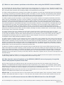
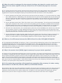
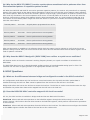
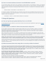
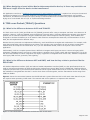
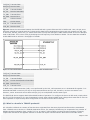
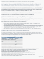
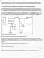
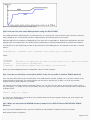
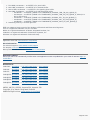
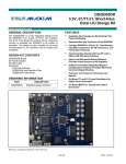
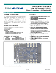
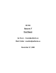
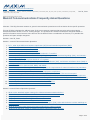
Maxim > App Notes > T/E Carrier and Packetized
Keywords: difference, T1, E1, channel, frame, superframe, extended, ESF, SF, D4, CRC-4, CAS, multiframe, CCS, RBS,
robbed bit, AIS, RAI, DMA
Dec 20, 2001
APPLICATION NOTE 590
Maxim® Telecommunications Frequently Asked Questions
Abstract: This FAQ discusses answers to general communication questions as well as Maxim device-specific questions.
This set of FAQs is designed to address some of the more common questions that may arise when using Maxim
telecommunication devices in new or existing designs. The questions are divided into different categories based on
specific information areas. Because some devices like the DS2155 have a combination of features, it is possible that
questions will span multiple categories.
Revision: June 25, 2009
Section 1. General Telecommunication Questions
1.
2.
3.
4.
5.
6.
7.
8.
9.
10.
11.
12.
13.
14.
15.
16.
In T1, what is the difference between superframe (SF)/D4 and extended superframe (ESF)?
What is the difference between T1 and E1?
What is the difference between T1 and J1?
What is SLC-96 and how does it relate to T1?
How are frames, channel time slots, and bits numbered in T1 and E1?
What are the differences between robbed-bit signaling (RBS), channel-associated signaling (CAS), and commonchannel signaling (CCS)?
What are the red, blue, and yellow alarms in a T1 system?
What are the alarm indication signal (AIS), remote alarm indication (RAI), and distant multiframe alarm (DMA) in
an E1 system?
What is the difference between AMI, B8ZS, and HDB3?
What are the names of the regulatory bodies that govern the requirements for network interface line protection?
What is the difference between jitter and wander?
What standards bodies govern telecommunications equipment compliance?
When the boundary scan is not used, what will be the pin conditions for the JTAG test access pins?
For a universal T1/E1 interface on the customer side, do T1/E1 service providers expect customer equipment to
provide a connection between the Tx and Rx pairs through the transformer center taps? Or, can the T1/E1 service
provider ignore this connection and leave it out of the design?
What is the difference between channelized and unchannelized T1?
Can I modify the codes of Maxim telecommunication drivers?
Section 2. General Device Operation Questions
1.
2.
3.
4.
5.
6.
What are the standard register settings for a Maxim telecommunication device?
What software is available for use with Maxim telecommunication devices?
Can you provide an example design using various processors?
Can you provide a reference design for the network interface?
What is the meaning of the markings on Maxim devices?
What is the difference between the device identification register (IDR) value and the device revision markings on
Maxim devices?
7. What do the suffixes after Maxim telecommunication device names indicate?
8. What kind of operating system is needed for Maxim telecommunication drivers?
Page 1 of 22
Section 3. Framer/Single-Chip Transceiver Questions
1. How are the DS21x5y, DS215y, or other telecommunication devices initialized?
2. Do Maxim telecommunication devices support unframed or transparent-mode operation?
3. Is it necessary to repeat the same data on the TSIG pin for an entire multiframe when using hardware-based
signaling?
4. How are JTAG functions implemented on SCT multichip modules such as the DS21Q352/DS21Q55?
5. Is the DS2155 pin compatible with other Maxim SCTs?
6. Do Maxim T1 devices support SLC-96?
7. What are some common problems and solutions when using the DS2155 internal HDLCs?
8. Why does the external loopback on the DS26401/DS2155 not work properly, even though the remote and
payload loopbacks work fine?
9. What are the differences between the DS21455/DS21458 and the older DS21Q55?
10. What is the functional behavior of the RCLK pin output when the signal at the network connection of RTIP/RRING
is lost?
11. When operating T1/E1 devices in T1 mode, can the TCLK pin input frequency be 2.048MHz?
Section 4. Line Interface Questions
1.
2.
3.
4.
5.
6.
7.
8.
9.
10.
What transformers are recommended for the Maxim telecommunication devices?
What is the function of the capacitor in the transmit path?
When using the DS2148 LIU in NRZ mode, how should the signals for the TPOS and TNEG pins be connected?
What are the selection criteria for the line build-out (LBO) bits in E1 applications?
When the cable is unplugged for the network interface, why does the receive carrier loss (RCL) bit in the status
register or the pin of the LIU or SCT occasionally report an incorrect status?
What are the differences between the DS21448 and the older DS21Q48/DS21Q348?
Why is the master clock (MCLK) signal necessary for proper device operation?
Is the center-tap connection of the transformer secondary side necessary for better analog performance of the
DS3151, DS3152, DS3153, and DS3154 devices?
Is it possible to use a sine-wave oscillator instead of a square-wave oscillator to supply different frequencies at
the CLAD for the DS325x?
Does the DS26334 LIU support internal impedance-matched operation? If so, what are the steps to program the
device in this mode?
Section 5. BERT Questions
1. When using the DS2155, DS2172, or DS2174 bit-error-rate tester (BERT) function with a pseudorandom bit
stream (PRBS) pattern, what status bits must be checked to validate that the pattern is being correctly received?
2. Why do the DS2172/DS2174 BERT devices remain in synchronization when the clock signal applied to the receive
clock (RCLK) pin is removed or held in a steady state?
3. How is the latch-count (LC) bit used to set the time interval for the bit and error counters of the DS21372,
DS2172, and DS2174?
4. Why do the DS21372/DS2172 receive synchronizers sometimes lock to patterns other than the transmitted
pattern in repetitive-pattern mode?
5. Why does the DS2174 design kit (DS2174DK) have neither a crystal nor an oscillator?
Section 6. HDLC Questions
1. What are the differences between bridge and configuration modes in the HDLC controller?
2. Does the DS31256 HDLC controller support 8-bit local bus mode?
3. How is the absolute address calculated in DS31256 HDLC controller?
Page 2 of 22
Section 7. Design Kit Questions
1.
2.
3.
4.
How can I get the most updated definition files for the T1E1DK?
What software is available for Maxim telecommunication design kits?
What telecommunication design kits are currently available from Maxim?
When designing a board with a Maxim telecommunication device, is there any restriction on PCB trace length from
the device to the transformer?
Section 8. TDM-over-Packet (TDMoP) Questions
1.
2.
3.
4.
5.
6.
7.
8.
9.
10.
11.
12.
What is the difference between VoIP and TDMoIP?
What is the difference between MII and RMII, and how do they relate to products like DS34T108?
What is a bundle in TDMoIP products?
I am getting bit errors with the DS34T108 in E1 internal mode when I use all 8 ports. All other modes operate
correctly. What is the cause of the errors, and is there a solution?
What kind of OAM packets are supported by TDMoP product support?
What is ARP and how does it work on Maxim TDMoP devices?
What are the ground considerations when using an Ethernet PHY interface?
Can you define the Stratum level for TDMoP devices?
What is the difference between TIE and MTIE?
How can the user send OAM packets using the DS34T108?
How do you find the correct jitter buffer index for a bundle in Maxim TDMoP devices?
What are the external SDRAM memory maps for the DS34T10x and DS34S10x TDMoP devices?
1. General Telecommunication Questions
Q1. In T1, what is the difference between superframe (SF)/D4 and extended superframe (ESF)?
A1. While both formats contain the same number of channel time slots, the SF format is a 12-frame structure, while ESF
contains 24 frames. Both use the 8th bit of each channel time slot in every 6th frame for signaling, thus providing the SF
format with A/B signaling bits and the ESF format with A/B/C/D signaling bits every multiframe. Also, the ESF format uses
the F bits to provide frame alignment, CRC-6 check bits, and a 4kbps data link. The SF format divides the F bits into Ft
and Fs bits. The Ft bits are terminal-framing bits that identify frame boundaries, and the Fs bits are signaling-framing bits
that identify signaling frames.
Q2. What is the difference between T1 and E1?
A2. The main differences between T1 and E1 are the operating frequency, the number of time slots, the pulse shape, the
characteristic line impedance, and the signaling method. The T1 system operates at 1.544MHz with a total of 24 time
slots. The T1 pulse shape contains overshoot and undershoot and is driven on a line impedance of 100Ω. Finally, digital
messages to signal on/off-hook or other conditions are sent using robbed-bit signaling. The E1 system operates at
2.048MHz with a total of 32 time slots. The E1 pulse shape is a perfectly rectangular pulse shape and is driven on a line
impedance of 120Ω or 75Ω. Finally, digital messages to signal on-/off-hook or other conditions are sent using channelassociated signaling.
Q3. What is the difference between T1 and J1?
A3. J1 commonly refers to the derivation of the North American T1 standard that is used exclusively in Japan. Differences
exist between J1 and T1 in the yellow alarm generation for superframe (SF) and extended superframe (ESF) modes. Also,
the CRC-6 calculation in ESF mode is different. In J1 SF mode, the yellow alarm is generated when a '1' is transmitted in
the 12th F-bit, as opposed to T1 SF mode in which a '0' is transmitted in the 2nd bit of all timeslots. In J1 ESF mode, the
yellow alarm is generated by transmitting 'FFFF' in the data link (DL) section of the F-bits, as opposed to T1 ESF mode in
which 'FF00' is transmitted in the data link. In J1 ESF mode the CRC-6 calculation includes the frame alignment signal and
data link F-bits. However, for T1, all of the F-bits are set to '1' when the CRC-6 calculation is performed.
Page 3 of 22
Q4. What is SLC-96 and how does it relate to T1?
A4. SLC-96 (pronounced "slick 96") is used in conjunction with T1 as a digital-loop carrier system, which provides service
for up to 96 subscribers over three to five separate T1 lines. SLC-96 was the first widely deployed digital-loop carrier
system. SLC-96 operation consists of two terminals: a central-office terminal (COT) and a remote terminal (RT). The COT
multiplexes the analog phone lines from a class 5 switch into four T1 lines with an optional fifth T1 line used for protection
switching. The RT is the termination point for the T1 lines and converts them into subscriber phone lines. SLC-96
revolutionized the telecommunication industry by introducing digital electronics into the local loop as a permanent
replacement for cable. The frame format of SLC-96 closely resembles that of the super-frame (SF or D4) format, except
that additional data-link information is transferred in the framing bits. This allows the deployment of advanced functions
such as single-party, multiparty, coin-telephone, and special-service circuits. For more information on SLC-96, please
consult Telcordia specification TR-008.
Q5. How are frames, channel time slots, and bits numbered in T1 and E1?
A5. According to the ITU-T specification G.704, the numbering structures for T1 and E1 digital transmission systems are
as follows:
In T1 systems, the frames are numbered 1 to 12 in the SF/D4 format, and 1 to 24 in the ESF. The channel time slots are
numbered 1 to 24. The bits are numbered 1 to 8, with the 8th bit being the least significant bit (LSB).
In E1 systems, the frames are numbered 0 to 15 in the CRC-4 and CAS multiframe formats. The channel time slots are
numbered 0 to 31. The bits are numbered 1 to 8, with the 8th bit being the least significant bit (LSB).
Q6. What are the differences between robbed-bit signaling (RBS), channel-associated signaling
(CAS), and common-channel signaling (CCS)?
A6. RBS is the original signaling system used by T1 and provides either 2 or 4 signaling bits per channel depending on the
multiframe format. In RBS, the LSB in every channel of every 6th frame is used as a signaling bit. Hence, in the SF
format there is an A/B bit for every channel, and in the ESF format there is an A/B/C/D bit. CAS is the original signaling
system used by E1 and provides 4 signaling bits for every channel. In CAS, channel 16 is reserved for signaling and
the A/B/C/D bits for each channel are divided among 16 frames. Frame 0 contains the alignment signal, alarm, and spare
bits. Frame 1 contains the A/B/C/D bits for channel 1 in the upper half of the channel, and the A/B/C/D bit for channel 16
in the lower half. The remaining 14 frames follow the frame 1 format accordingly. In recent years, the term RBS has been
replaced by CAS, which is now used to refer to bits that are associated with a specific channel whether it is in the T1 or
E1 format. CCS is used by either T1 or E1 and refers to a system that does not use a specific bit structure for signaling.
Instead, all or part of a channel is used to pass messages between two systems to indicate how a channel is being used.
This type of system is commonly found in ISDN, which uses a D channel to pass messages.
Q7. What are the red, blue, and yellow alarms in a T1 system?
A7. The three different alarms are used to indicate different problems in transmission or reception of data in the T1
system. To explain the different alarms, it is necessary to have a simple T1 system model that has a T1 signal sourced
from the central office (CO) through a repeater to the customer premises equipment (CPE) and back. The red alarm is
actually a CPE state resulting from the detection of an incoming signal failure (i.e., from a line break). The yellow alarm is
transmitted to indicate the loss of an incoming signal. In the case where the CPE is in the red alarm state, it will transmit
the yellow alarm to the repeater. The blue alarm is transmitted upon loss of the originating signal or when a signal is
actively disrupted. In the case where the repeater receives the yellow alarm, it will transmit the blue alarm back to the
CO. Upon receiving a blue alarm, the CO will transmit a yellow alarm to the repeater to indicate the loss of incoming
signal. It may seem confusing as to whether a piece of equipment should transmit a yellow or blue alarm. Generally, any
piece of equipment on the endpoint (i.e., a CPE or a CO) will transmit the yellow alarm to indicate the loss of signal, while
equipment in the middle of the path (i.e., a repeater) will transmit the blue alarm.
Q8. What are the alarm indication signal (AIS), remote alarm indication (RAI), and distant
multiframe alarm (DMA) in an E1 system?
A8. The AIS and RAI are essentially the same as the T1 blue and yellow alarm, respectively. The AIS is transmitted upon
loss of the originating signal or when the incoming signal is actively disrupted. The RAI is transmitted to indicate the loss
of an incoming signal. The DMA is specific to CAS signaling and is transmitted when the correct CAS multiframe alignment
signal is not found.
Page 4 of 22
Q9. What is the difference between AMI, B8ZS, and HDB3?
A9. AMI, B8ZS, and HDB3 are different types of line coding used in T1 and E1 communications systems. AMI (alternate
mark inversion) is used in both T1 and T1 systems. B8ZS (bipolar with 8 zeros substitution) is used in T1 systems. HDB3
(high-density bipolar 3) is used in E1 systems.
AMI is the most basic encoding scheme, in which ones are represented by voltage pulses and zeros are represented by
the lack of a voltage pulse. In AMI, the polarity of each pulse is the opposite of the previous pulse. The problem with
using AMI is that if not enough voltage pulses are sent down the line, the receiver will not correctly decode the data
stream.
To solve this problem, two different encoding schemes were developed to replace a sequence of zeros with a special code
word of voltage pulses. The B8ZS encoding scheme replaces each sequence of 8 zeros with the code of 000VB0VB, where
the V pulse (bipolar violation) has the same polarity as the previously pulse and the B pulse (correct bipolar pulse) has
the opposite polarity as the previous pulse. HDB3 encoding is slightly more complicated because, unlike the B8ZS
encoding that has a balance of positive and negative voltage pulses, the HDB3 encoding must select a code word to
maintain the balance. In HDB3, each sequence of 4 zeros is replaced by 000V or B00V. The decision of which code word
to use is made so that the number of B pulses between consecutive V pulses is odd. This maintains the balance of positive
and negative pulses when using HDB3 encoding. The table below shows examples of the different encoding types.
*The previous V bit is directly before the beginning of the data sequence.
Q10. What are the names of the regulatory bodies that govern the requirements for network
interface line protection?
A10. There are many different regulatory bodies that govern how the T1 and E1 line interfaces must operate under surge
and power cross conditions. The list below contains the commonly referenced regulatory bodies and the specifications that
apply in each case.
FCC Part 68: Effective July 23, 2001, the Administrative Council for Terminal Attachments (ACTA) assumed operational
responsibility for Part 68. ACTA is the newly-formed industry council for Part 68 certification requirements and
administration. This followed the FCC's decision to privatize its Part 68 responsibilities and select TIA and ATIS to serve as
joint sponsors of the Council. Because of this, FCC Part 68 has been renamed to be TIA/EIA-IS-968.
Old Part 68 URL: www.fcc.gov/wcb/iatd/part_68.html
New Part 68 URL: www.part68.org
UL 1950: Underwriter Laboratories has made changes to the naming of the over-voltage specifications known as UL 1950,
3rd edition. This specification is now referred to as UL 60950, 3rd edition.
Old UL1950 URL: www.ul.com/pag1950
New UL60950 URL: data.ul.com/pagos
Q11. What is the difference between jitter and wander?
A11. Jitter is defined as the magnitude of phase variation (with respect to a reference clock or data signal) whose
frequency of variation is greater than 10Hz. Jitter is measured in unit intervals (UI), where 1 UI is equal to one data bitwidth. For an E1 signal, 1 UI is equal to 488ns, and for a DS1 signal, 1 UI is equal to 648ns. However, if the rate of
change in phase is less than 10Hz, then this phenomenon is known as wander and is measured in nanoseconds.
Q12. What standards bodies govern telecommunications equipment compliance?
A12. The following is a list of the largest telecommunications standards bodies:
Page 5 of 22
●
●
●
●
●
●
●
American National Standards Institute - ANSI (www.ansi.org)
European Telecommunications Standards Institute - ETSI (www.etsi.org)
International Telecommunication Union - ITU (www.itu.int)
Telecommunication Technology Committee - TTC (www.ttc.or.jp)
Telecommunications Industry Association - TIA (www.tiaonline.org)
Telcordia Technologies, Inc. - Telcordia (www.telcordia.com)
Underwriters Laboratories, Inc. - UL (www.ul.com), UL Europe (www.ul-europe.com)
Q13. When the boundary scan is not used, what will be the pin conditions for the JTAG test
access pins?
A13. For the boundary scan, each device uses five pins. These are the JTCLK, JTDI, JTMS, JTRST, and JTDO pins. When
the boundary scan is not used, these pins must have a steady value. For JTCLK, it should be pulled high. JTDI and JTMS
should be unconnected or high, because they both have an internal 10kΩ pullup resistor. JTRST also has a 10kΩ pullup
resistor, and it asynchronously resets the test access port when the pin is toggled from low to high. It needs to be held
high or low when the boundary scan is not used. JTDO should be left unconnected.
Q14. For a universal T1/E1 interface on the customer side, do T1/E1 service providers expect
customer equipment to provide a connection between the Tx and Rx pairs through the
transformer center taps? Or, can the T1/E1 service provider ignore this connection and leave it
out of the design?
A14. The need for transformer center tap connection between the Tx and Rx pairs depends on the design and, most of
the time, it is recommended that this connection is ignored. Most T1 service providers do not expect there to be a
connection between the transformer center taps of Rx and Tx pairs.
Please refer to application note 324, "T1/E1 Network Interface Design," for more information regarding design of a
telecommunications network interface circuit using Maxim line interface units (LIUs) or single-chip transceivers (SCTs).
For an E1 network, hardware board designers cannot connect the center taps of Rx and Tx at any time. For a T1 network,
the designers need to make sure that they are using 5V parts if they want to connect the center taps of Rx and Tx sides
of the transformer. With 3.3V parts, however, they cannot connect the center taps.
If the customer is planning to create a new design with DS2155/DS2156, then it is recommended to refer to Figures 4
and 5 of application note 324. However, if the customer is using the DS2151 or DS2153, then it is recommended to refer
to Figures 2 and 3 instead.
Q15. What is the difference between channelized and unchannelized T1?
A15. Channelized T1 splits into 24 voice-grade channels, with each running at 64kbps. If you have a need for numerous
local phones, it is much cheaper to get them delivered on T1 channels than as individual phone lines. Channelized T1 is
developed and optimized for uncompressed voice communications. The channelized approach is required for access to the
tradition PSTN.
Unchannelized T1 provides you with 1.536Mbps (minus a framing bit), which you can split up anyway you choose. It is
ideal for most data-communications applications, as well as compressed voice, video, and IP telephony. For example, you
can split a leased T1 into 12 voice-grade channels to support 12 voice conversations, and then use the remaining
768kbps for either reasonably high-speed access to the Internet or for videoconferencing with your distant office. You can
also compress voice to run at speeds of perhaps 8kbps or less by using IP telephone techniques and, therefore, put many
more voice calls over a single T1 pipe.
Q16. Can I modify the codes of Maxim telecommunication drivers?
A16. No. Maxim has the license of the driver that allows us to provide the driver code to the customers, but it does not
change the ownership of the driver nor put it under the GNU licensing schemes. The customer can extend the driver
through the macros or other recommended function commands.
Page 6 of 22
2. General Device Operation Questions
Q1. What are the standard register settings for a Maxim telecommunication device?
A1. Because there are many different ways that a T1, J1, E1, T3, or E3 device can communicate, there are no standard
register settings. After initialization, there are three register types that control all major device operations. These are the
receive control registers (RCRx), the transmit control registers (TCRx), and the common control registers (CCRx).
Q2. What software is available for use with Maxim telecommunication devices?
A2. Software drivers are available for the following T1/E1 devices:
DS2152, DS2154, DS21(Q)352, DS21(Q)552, DS21(Q)354, DS21(Q)554, DS21(Q)55, DS21455, and DS21458.
Software drivers are available for the following T3/E3 devices:
DS3112, DS3141, DS3142, DS3143, DS3144, DS3151, DS3152, DS3153, and DS3154.
The drivers are written in C and supplied by NComm. The drivers may be obtained by submitting an email request to
[email protected]. Please note that company contact information must be provided before the request can
be processed.
Q3. Can you provide an example design using various processors?
A3. There are several example designs using processors by various manufacturers located in the Communication Circuits
section of our online application notes.
Q4. Can you provide a reference design for the network interface?
A4. Application note 324, "T1/E1 Network Interface Design," provides all the information required to implement the
network interface.
Q5. What is the meaning of the markings on Maxim devices?
A5. Example markings for the DS2149 28-pin PLCC package:
MAXIM
DS2149 - Device
YYWWRR - Date code
###XX - Lot code
Date Code:
YY - Last two digits of the year of assembly
WW - Week within the year of assembly
RR - Revision
Lot Code:
### - Last three digits of the lot number
XX - Up to two alpha characters that are behind those digits
Q6. What is the difference between the device identification register (IDR) value and the device
revision markings on Maxim devices?
A6. The device revision, printed on the top of the package, consists of an alphanumeric combination that is two
characters in length. The alpha character denotes the current level of an all-layer die revision, with the first die being
denoted with the letter 'A'. The numeric character denotes the current level of a metal layer die revision, with the first die
being denoted with the number '1'. If only the metal layers of the die are revised, then the numeric portion is increased
by one. When all the layers of the die are revised, then the alpha portion is increased by one letter and the numeric
portion is returned to the number '1'. Further changes follow the same standard.
Page 7 of 22
For all Maxim T1/E1 devices with an 8-bit data bus, the device identification register (IDR) is eight bits in length. The
upper four bits are used to identify the device family (e.g., the DS2155, DS21354, DS21552, etc.) The lower four bits are
used to identify the specific revision of the die. Because the lower four bits cannot denote the same alphanumeric
combination as printed on the device, the binary value is simply increased by one when any revision is made to the die
with the value of '0000' indicating the 'A1' revision.
It should be noted that some Maxim telecommunication devices have a 16-bit data bus and follow a different
identification register model, which is detailed in the specific device's data sheet.
Q7. What do the suffixes after Maxim telecommunication device names indicate?
A7. Maxim creates new part numbers with different suffixes, such as DSxxxxL and DSxxxxLB, to separate the package
type, revision, and device type in inventory.
For example, The "L" in DS2155L indicates that the DS2155 is packaged in an LQFP, commercial type. Commercial type
devices have a temperature range of 0°C to +70°C. The "G" in DS2155G indicates that the DS2155 is packaged in a
CSBGA, commercial type. The "LN" in DS2155LN indicates that the DS2155 is packaged in an LQFP, industrial type.
Industrial type devices have a temperature range of -40°C to +85°C. The suffix may also represent a different package
outline drawing or materials analysis.
Q8. What kind of operating system is needed for Maxim telecommunication drivers?
A8. Maxim telecommunication device drivers are written in C and supplied by NComm. The software is designed to be
operating system independent and portable across different operating systems/platforms, such as Windows®, Linux®,
and VxWorks®. The user can integrate the driver with their application that is not directly functional on the operating
system. The user needs only to create code that makes the driver to work within its environment.
Maxim telecommunication device drivers can be obtained by submitting an email request to telecom.support@maxim-ic.
com. Please note that company contact information must be provided before the request can be processed.
3. Framer/Single-Chip Transceiver Questions
Q1. How are the DS21x5y, DS215y, or other telecommunication devices initialized?
A1. Some devices like the DS2155 T1/E1 SCT or DS2148 LIU, offer a power-on reset and a hardware reset pin that clears
out all the registers. Other devices require software to write a 0x00 to address space 0x00 to 0xFF, regardless of register
type or documented presence. This ensures that all of the registers are cleared and the device is in normal operation
mode.
Q2. Do Maxim telecommunication devices support unframed or transparent-mode operation?
A2. Yes. A description of how to configure a device for unframed or transparent-mode operation is provided in application
note 336, "Transparent Operation on T1, E1 Framers and Transceivers."
Q3. Is it necessary to repeat the same data on the TSIG pin for an entire multiframe when using
hardware-based signaling?
A3. Yes. The chip is designed to expect signaling data during the least significant nibble throughout all timeslots and all
frames of a multiframe. Failure to do so causes unstable results.
Q4. How are JTAG functions implemented on SCT multichip modules such as the DS21Q352/
DS21Q55?
A4. A multichip module is any device that contains multiple die or devices housed in the same package. The DS21Q352,
DS21Q354, DS21Q552, DS21Q554, and DS21Q55 are all examples of quad-port, SCT multichip modules. Each of these
multichip modules has four single-port devices with daisy-chained JTAG functionality. This is necessary because each
Page 8 of 22
single-port device contains a JTAG test access-port controller, and because the BSDL language lacks the ability to define
multiple test access-port controllers. In the module, some pins such as address and data buses are tied together. The
JTAG pins are either tied in parallel or daisy-chained, as appropriate. More detail can be found in the device's data sheets.
To create the proper JTAG scan chain, four copies of the single-port version of the device need to be placed in the JTAG
chain. For example, if a DS21Q55 were placed on the board, the proper BSDL file would be the DS2155.
When using multichip modules in the JTAG chain, the design may need to be modified slightly to reflect the internal
connections present in the module. The amount of modification depends on whether the module is being used on a
physical tester or in conjunction with a simulation program. If the module is being used on a physical board, then the
implementation will only require that four copies of the single-port BSDL file to be placed sequentially in the JTAG test
chain. However, if the module is being used in a simulation, the implementation may be slightly more complex.
The first way to create a useful simulation model is to create a hierarchy in the design. The quad-port module is
considered to be a separate board made of four single-port devices. The connections are then made to match those
present inside of the module itself; these connections are detailed in the device data sheet. Another way is to directly
alter the netlist after the design is complete. This will essentially trick the simulation into believing that the quad-port
module is four separate single-port devices.
BSDL files are available on the Maxim website.
Q5. Is the DS2155 pin compatible with other Maxim SCTs?
A5. The DS2155 is closely pin compatible with DS2152/DS2154, DS21552/DS21554, and DS21352/DS21354 SCTs. The
biggest difference between the DS2152/DS2154, DS21552/DS21554, and the DS2155 or DS21352/DS21354 devices is
that the former devices all operate on 5.0V, while the latter operate on 3.3V (with 5.0V I/O tolerance). The DS2152/
DS2154 also do not support many of the pins/functions that the DS2155 has available. The DS21552/DS21554 and
DS21352/DS21354 offer the best compatibility, but there are some pins/functions that were changed between the
DS21x5y and the DS2155. The table below notes all the differences between the devices' pins.
Pin
Part
DS2152/DS2154 DS21552/DS21554 DS21352/DS21354 DS2155
Supply Voltage (V)
5.0
5.0
3.3
3.3
Pin 2
NC
JTMS
JTMS
JTMS
Pin 3
8MCLK
8MCLK
8MCLK
BPCLK
Pin 4
NC
JTCLK
JTCLK
JTCLK
Pin 5
NC
JTRST
JTRST
JTRST
Pin 7
NC
JTDO
JTDO
JTDO
Pin 8
NC
NC
NC
UOP0
Pin 9
NC
NC
NC
UOP1
Pin 10
NC
JTDI
JTDI
JTDI
Pin 14
TEST
TEST
TEST
TSTRST
Pin 15
NC
NC
NC
UOP2
Pin 23
NC
NC
NC
UOP3
Pin 36
NC
CI
CI
ESIBS0
Pin 54
NC
CO
CO
ESIBS1
Pin 76
NC
FMS
FMS
ESIBRD
Q6. Do the Maxim T1 devices support SLC-96?
A6. Because of the complexity of the SLC-96 specification, special synchronization circuitry, data registers, and status
registers were added to the T1 devices that allow the system designer to take advantage of the SLC-96 functionality.
Maxim T1 devices like the DS2141A, DS2151, DS2152, DS21352, DS21552, and DS2155 are capable of SLC-96 operation
in both transmit and receive directions. On the receive side, the devices are able to synchronize onto a received SLC-96
pattern and extract the message bits. On the transmit side, the devices are able to insert the SLC-96 synchronization
pattern and message bits. The devices also have the option to perform SLC-96 functions externally through hardware pins
or internally through software registers and interrupts.
Page 9 of 22
Q7. What are some common problems and solutions when using the DS2155's internal HDLCs?
A7. The DS2155 SCT has the ability to transmit and receive packet data over a T1/E1 or J1 line. This device contains two
high-level, data-link controllers (HDLC), each of which can be configured for use with time slots, Sa bits (E1 mode), or the
FDL (T1 mode). Each controller has a 128-byte FIFO in the transmit and receive paths.
The most common problems are receiving incorrect data in the packets, not receiving enough data bytes in the packets,
or receiving a prematurely terminated (aborted) packet. Fortunately, for each controller, the DS2155 provides separate
registers that contain information about any errors that occur when receiving data. These registers provide a basis for
what action, if any, the system needs to perform for continuous normal operation.
The HDLC registers provide information on the following receive packet conditions: In Progress, Packet OK, CRC Error,
Abort, Overrun, and Message Too Short. The first condition, In Progress, means the HDLC is receiving a packet and no
alarms have been detected. Depending on the system, certain actions such as retrieving data from the FIFO may be
necessary. The second condition, Packet OK, means the HDLC received a correctly formatted packet, and the data has
been checked against the transmitted CRC bytes. The third condition, CRC Error, occurs when the calculated CRC for the
received data does not match the transmitted CRC bytes in the packet. The fourth condition, Abort, happens when the
HDLC receives the abort signal. The fifth condition, Overrun, occurs when the receive FIFO exceeds the maximum
capacity of 128 bytes. This usually indicates that the microcontroller did not read the FIFO data faster than the DS2155
writes the received data into the FIFO. The final condition, Message Too Short, indicates that 3 or fewer bytes, including
the CRC bytes, were received as a message.
The cause of some of the error conditions can be found by simple line testing, while others may require in-depth
knowledge of the system software. There are two main causes of CRC errors: either the transmission line quality is poor,
or there may be problems with the HDLC software/hardware on the transmit or receive side. Testing the line quality is
accomplished by performing a bit error-rate test while in remote loopback. If the line is not the problem, further
investigation into the HDLC software/hardware is required.
The Abort condition is difficult to solve because the cause is most likely on the transmit side, which may not be under the
designer's control. A common cause is a buffer under run condition in the transmit FIFO, which occurs when the transmit
HDLC needs to send data, but the processor has not written data into the FIFO. Sometimes, a faster processor solves the
problem, but changes often need to be made in the software/hardware. The DS2155 has special "watermark" registers
that the processor can use as indicators of the current FIFO status. The 'watermark' registers can be serviced in either a
polled mode or can be interrupt-driven to ease the processor load.
The Overrun condition is caused when the processor does not read data out of the receive FIFO as fast as the receive
HDLC writes data into the FIFO. Similarly, a faster processor may solve this problem, but again changes may need to be
made in the software/hardware. The DS2155 has special 'receive packet bytes available' and 'watermark' registers that
the processor can use as indicators of the current FIFO status. The 'receive packet bytes available' register is a simple
indication of how much data is currently in the FIFO, while the 'watermark' registers can be serviced or interrupt driven as
described above.
The Message Too Short condition is very easy to deal with—it is used to indicate that the HDLC packet received did not
contain enough data and, as such, is an illegal packet and should be ignored.
Q8. Why does the external loopback on the DS26401/DS2155 not work properly, though the
remote and payload loopbacks work fine?
A8. The cause for this error could be that you are not using the correct source for the transmit clock (TCLK) in the
DS26401. The DS26401DK was designed with three major components: a LIU, a framer, and a FPGA for specific signal
multiplexing. Unfortunately, the receive clock from the LIU goes to the DS26401 and a test-point header, but not to the
FPGA. Therefore, to perform an external loopback, you need a way to connect RCLK to TCLK.
Solution One Manually jumper RCLK and TCLK on the DS26401DK with the test-point headers. Make sure the TCLK
register in the FPGA is three-stated. This is the default value.
Solution Two You can control the source on the transmit clock with TCR3 register (TCR) using Bit 4 (TCSS0) and Bit 5
(TCSS1). Set TCSS0 and TSSC1 to a logic "1". This will cause the transmit clock to be the same as RCLK from the LIU.
Q9. What are the differences between the DS21455/DS21458 and the older DS21Q55?
A9. The DS21Q55 is a quad-port, 27mm x 27mm multichip module consisting of four independent DS2155 transceivers.
Page 10 of 22
The DS21455 is a monolithic version of the DS21Q55, and is meant to be a drop-in replacement that is package, pin, and
software compatible. The DS21458 contains exactly the same die as the DS21455 and is software compatible, but it is
produced in a smaller, 17mm x 17mm package. Note: New designs should use the DS21455 instead of the DS21Q55.
Q10. What is the functional behavior of the RCLK pin output when the signal at the network
connection of RTIP/RRING is lost?
A10. When the device loses the signal at the network connection of RTIP/RRING, it enters the carrier-loss state. In this
state, the RCLK output will slowly drift from the recovered clock, which is no longer present, to the master clock (MCLK)
input. Once the network connection is restored, the RCLK output will again lock with the signal present on RTIP/RRING.
Q11. When operating T1/E1 devices in T1 mode, can the TCLK pin input frequency be 2.048MHz?
A11. T1/E1 devices (such as the DS2155, DS21458, and DS26528) provide a wide range of features aimed at easing
device configuration. One of these features is the ability to use a single-frequency master clock (MCLK) in either T1 or E1
mode. Unfortunately, the device still requires that the external TCLK pin input be at the actual line frequency. In T1
mode, this means the input frequency on the TCLK pin must be 1.544MHz. However, there are some ways around this
limitation, using either the elastic stores for rate conversion, or using the master clock PLL to source TCLK internally at
1.544MHz.
4. Line Interface Questions
Q1. What transformers are recommended for the Maxim telecommunication devices?
A1. A listing of recommended transformers is provided in application note 351, "T1/E1 and T3/E3 Transformer Selection
Guide," and in the last section of the application note 324, "T1/E1 Network Interface Design."
Q2. What is the function of the capacitor in the transmit path?
A2. The reason that the capacitor exists is to block the flow of current between the TTIP and TRING pins, preventing
unnecessary power draw. The capacitor value stated in the data sheet was chosen so that it appears as a short circuit at
the transmission frequency and an open circuit at DC. Although the value is somewhat subjective, this value has been
proven to work with all Maxim telecommunication devices and should not be altered. If the value must be changed,
another value can be calculated by the formula f = 1/RC. R is the load as seen by the device (1/4 of the line impedance),
C is the capacitor value, and f is the mean signal frequency. Remember that an all ones signal appears as 772kHz, and a
lower ones density decreases the signal frequency. The capacitor must be chosen such that the signal frequency is not
blocked.
Q3. When using the DS2148 LIU in NRZ mode, how should the signals for the TPOS and TNEG
pins be connected?
A3. Connect the NRZ input to TPOS and tie TNEG to ground.
Q4. What are the selection criteria for the line build-out (LBO) bits in E1 applications?
A4. The criteria depend not only on the intended application for the SCT, but also to what type of system the design is
interfacing. The line interface circuit can be designed many ways and the following applications explain the difference in
the three major operations obtained by switching the LBO.
75Ω/120Ω Normal This is used for E1 short haul, when the system will be used in a confined environment where the
return loss is insignificant and there will be no exposure to lighting surges or power-line cross conditions.
75Ω/120Ω with Protection Resistors or 75Ω/120Ω with High Return Loss These two operations are used for E1
long haul, when the system will interact with the outside environment. Here, the return loss is also considered to be
insignificant. In order protect the system from lighting surges and power-line cross conditions, power resistors are placed
in between the RJ48 connector and the network side of the transformer.
Page 11 of 22
Q5. When the cable is unplugged for the network interface, why does the receive carrier loss
(RCL) bit in the status register or the pin of the LIU or SCT occasionally report an incorrect
status?
A5. It is unlikely that the device actually reports the RCL status incorrectly. The most common cause of this problem is
that a noise/signal source is coupling into the receive-side interface (the RTIP and RRING pins). The following are
suggestions to verify that noise/signal coupling is the problem and what can be done to solve the problem.
1. Set the equalizer gain limit (EGL) of the device to the lower of the two settings (i.e., if the two choices are -43dB
and -15dB, choose the -15dB setting). This will allow the LIU to remove low-level signals that may be causing the
device to report the RCL status incorrectly. If this solves the problem, then the EGL bit can be left at this setting
for future operation. However, if long-haul operation is required by the system, another suggestion should be
considered.
2. Set the transmitter power-down (TPD) of the device to turn off the transmitter. This will prevent the transmitted
signal from coupling into the receiver. If this solves the problem, then the problem is probably that the transmit
TIP/RING signals are too close in proximity to the receive TIP/RING signals. The best solution is to examine the
layout of the board and shorten the TIP/RING traces and further separate the transmit and receive signals.
3. When the line is disconnected, use an oscilloscope to probe the receiver TIP/RING pins to observe any noise that
may be present. If there is a large amplitude and noise on the line with a frequency near the nominal line rate,
this noise can be falsely recovered as a signal. The best solution is to examine the board to find the source of the
coupled noise and move or shield it from the receiver pins.
4. Use an oscilloscope to probe the power supply directly at the supply pins of the device. If there is noise with an
amplitude of 50mV or greater superimposed on the power-supply rail, then it can cause problems with the
receiver. The best solution is to use decoupling capacitors to filter the power supply to reduce the noise.
Q6. What are the differences between the DS21448 and the older DS21Q48/DS21Q348?
A6. The DS21Q48 and DS21Q348 are quad-port, 17mm x 17mm multichip modules that consist of four independent LIUs.
The DS21Q48 operates at 5.0V and is composed of DS21Q48 devices, while the DS21Q348 operates at 3.3V and is
composed of DS21348 devices. The DS21448 is a monolithic version of the DS21Q348, and is meant to be a drop-in
replacement that is package, pin, and software compatible. The DS21448 only operates at 3.3V and cannot be used as a
direct replacement for the DS21Q48.
Q7. Why is the master clock (MCLK) signal necessary for proper device operation?
A7. Because of the hybrid analog and digital nature of the line interface, the master clock signal present on the MCLK pin
is necessary to operate both the clock- and data-recovery engine and the jitter attenuator. Without the master clock, the
device would not be able to properly recover the clock and data signal present on the incoming line. The master clock
signal is also used as an alternate recovered clock on the RCLK pin whenever the device enters a receive carrier loss
state. To ensure that the device operates within specifications, the master clock should be derived from an accurate lowjitter source such as a crystal oscillator. T1/E1 devices usually use a source with a frequency tolerance rating of ±50ppm
(or better) and a period jitter rating measured in picoseconds.
Q8. Is the center-tap connection of the transformer secondary side necessary for better analog
performance of the DS3151, DS3152, DS3153, and DS3154 devices?
A8. Connecting the center tap of the transformer secondary side to the ground is optional. If used, the center tap if used
would serve to reduce the common-mode noise. However, the DS315x devices are all designed to use a coaxial cable
connection, which has little if any common-mode noise. In addition, if the traces between the transformer and the
DS315x device pins are short in length, the effects of inductance and common-mode noise will be negligible.
Page 12 of 22
Q9. Is it possible to use a sine-wave oscillator instead of a square-wave oscillator to supply
different frequencies at the CLAD for the DS325x?
A9. Yes. It is possible to use a sine-wave oscillator to supply sinusoidal frequencies to the input of the DS325x's CLAD.
The lowest voltage of the sine wave cannot go below the diode drop, and it is recommended that the voltage is a 3.0V
sine wave with minimum of 0V.
Q10. Does the DS26334 LIU support internal impedance-matched operation? If so, what are the
steps to program the device in this mode?
A10. Yes, the DS26334 does support internal impedance-matched operation for devices that are revision A2 or later.
Revision A1 does not support this mode. When the DS26334 is in internal impedance-termination mode, RTIP and RRING
require no external resistance components. However, for better internal resistance accuracy, a 16.5kΩ ±1% resistor is
required on the RESREF pin. For external termination mode, the RESREF pin must be tied to GND. It is also important to
note that, in internal impedance-termination mode, a 1:1 transformer on the receive side is required. If you are using a
1:2 transformer, a 30Ω resistor must be placed in parallel with RRTIP and RRING.
5. BERT Questions
Q1. When using the DS2155, DS2172, or DS2174 bit-error-rate tester (BERT) function with a
pseudorandom bit stream (PRBS) pattern, what status bits must be checked to validate that the
pattern is being correctly received?
A1. Status Register 9 (SR9 in the DS2155) should be checked to ensure that the BERT is in synchronization and that the
device is not receiving an all zero pattern. When properly receiving a PRBS pattern, the synchronization bit (SYNC or
BSYNC in the DS2155) equals 1, and the receive-all-zeros bit (RA0 or BRA0 in the DS2155) equals 0. When receiving a
PRBS pattern, it is important to verify that the receive-all-zeros bit equals 0 because the BERT uses a linear-feedback
shift register (LFSR), which enters a 'dead state' when it receives all zeros. If the receive-all-zeros bit equals 1, it is
possible for the BERT bit counters to begin counting received bits. This would result in the miscalculation of the bit-error
rate. Therefore, the receive-all-zeros bit should be checked whenever receiving a PRBS pattern.
Q2. Why do the DS2172/DS2174 BERT devices remain in synchronization when the clock signal
applied to the receive-clock (RCLK) pin is removed or held in a steady state?
A2. Both the DS2172 and the DS2174 can remain in synchronization when the clock signal applied to the receive-clock
(RCLK) is removed. This reason for this behavior is that the state machine that controls the receive synchronization is
clocked by the signal applied to the receive-clock pin. If the receive-clock signal is removed or held in a steady state, the
data in the status register will no longer get updated. During this time, however, read and write operations will all
continue to operate normally. The easiest method to determine if the signal present on the receive-clock pin is changing
is to read the bit-count registers. If the bit count remains the same with each consecutive read, there is no signal on the
receive-clock pin.
Q3. How is the latch-count (LC) bit used to set the time interval for the bit and error counters of
the DS21372, DS2172, and DS2174?
A3. Both the bit and error counters of the BERT devices contain a second shadow register that is used to latch the current
value. When the LC bit is set from 0 to 1, two events occur. First, the current value of the bit and error counters is
latched in the shadow registers. Second, the bit and error counters are cleared and will resume operation. The software
can then access the shadow registers to read the previous count values. To measure the bit and error counts from time
T0 to T1, the following procedure is necessary:
At time T0, set the LC bit from 0 to 1. This will clear the bit and error counters and latch the previous count values, which
can be discarded. At time T1, set the LC bit from 0 to 1. This will clear the bit and error counters and latch the count
values from time T0 to T1, which the software can access.
Page 13 of 22
Q4. Why do the DS21372/DS2172 receive synchronizers sometimes lock to patterns other than
the transmitted pattern in repetitive-pattern mode?
A4. When the DS21372 and DS2172 are used to generate repetitive patterns, the receiver only searches for a repeating
pattern of the same length as the pattern being transmitted. It does not verify that the receive pattern exactly matches
the transmit pattern. Once the device has received a pattern of equal length, synchronization is declared. The device will
then count any deviations in the received pattern as bit errors. A received pattern of all zeros or all ones will cause the
device to synchronize no matter which pattern length is being transmitted. Also, any receive pattern length that is an
even divisor of the transmit pattern length will cause the device to synchronize. Consider the following examples that
meet the criteria above.
Transmit pattern
10111000
Original pattern programmed into device
Receive pattern
10111000
Device synchronizes to correct pattern
Receive pattern
00000000
Device synchronizes to wrong pattern
Receive pattern
11110000
Device synchronizes to wrong pattern
Receive pattern
10101010
Device synchronizes to wrong pattern
After synchronization is established, the software should check the pattern-receive registers to verify that the correct
pattern is being received. Also, the receive-all-zeros and receive-all-ones indicators show that the status register can be
used for pattern verification.
Q5. Why does the DS2174 design kit (DS2174DK) have neither a crystal nor an oscillator?
A5. Because we do not know the customer's working frequency domain, no crystal or oscillator is included in the
DS2174DK.
The DS2174DK does have an on-board selectable oscillator and an on-board selectable analog input for TCLK. The
customer can use either a signal generator or an appropriate oscillator for TCLK.
6. HDLC Questions
Q1. What are the differences between bridge and configuration mode in the HDLC controller?
A1. Configuration mode allows only the local bus to control and monitor the chip while the HDLC packet data is
transferred through the PCI bus. Data cannot be passed from the local bus to the PCI bus in this mode.
Bridge mode allows the host on the PCI bus to access the local bus. The PCI bus is used to control and monitor the chip
and transfer the packet data. Data can be mapped from the PCI bus to the local bus.
Q2. Does the DS31256 HDLC controller support 8-bit local bus mode?
A2. Yes, the 8-bit local bus is available in bridge mode and has two distinct PCI functions.
Function 0 Allows read and write operations to the DS31256 registers through the PCI bus using 8- or 16-bit wide
access. However, this function does not allow access to the DS31256 registers, which perform read and write operations
on the local bus.
Function 1 Allows read and write operations from the PCI bus to the local bus. The software must configure the LBW bit
in the LBBMC register to define the width of the local bus as 8 or 16 bits wide.
Page 14 of 22
Q3. How is the absolute address calculated in the DS31256 HDLC controller?
A3. The absolute address, also known as the real address or machine address, is a fixed address in memory. The absolute
address is the base address plus the actual address being used by the device. For proper operation, the absolute address
must be allocated correctly when configuring the DMA controller in the device. The equation for calculating the absolute
address is:
Absolute Address = Base Address + Actual Address in Use
For example, consider the DS31256 HDLC envoy controller's receive done queue end address being used by the device.
The actual end address is not an absolute address. If the base address is 0x10000000 and the receive done queue end
address is 0x400, the calculation is:
0x10009000 + 0x400 * 4, and the absolute address is 0x1000A000.
7. Design Kit Questions
Q1. How can I get the most updated definition files for the T1E1DK?
A1. The definition files are available by request from the Maxim telecommunication applications support group (telecom.
[email protected]).
Q2. What software is available for Maxim telecommunication design kits?
A2. The software used with the Maxim telecommunication design kits is known as ChipView. ChipView is a PC-based
demonstration program that is used to interact with Maxim T/E carrier design kits. The program has been written to
control all T/E carrier design kits that utilize either a serial or USB port. ChipView has three basic modes of operation:
demo mode, register view, and terminal mode.
Demo mode provides a high-level user interface for configuring the device registers on the daughter cards using radio
buttons and menu selections. The current device status for functions such as LOS, OOF, and AIS is displayed with easy-toread widgets. This interface is meant to make device configuration as easy as possible.
Register view mode provides an intuitive user interface for reading, writing, and viewing the individual device registers on
the daughter card. The device registers are displayed by name in an on-screen array, and the values can be changed
using the keyboard or mouse. This interface provides complete control of every bit and function of the specific device.
Terminal mode provides direct access to the design kit's processor. The list of all recognized commands is listed when the
user types "help" or "?" at the command prompt. This mode is for low-level debugging of the daughter card and should be
reserved for seasoned users.
Q3. What telecommunication device design kits are currently available from Maxim?
A3. There are two kinds of telecommunication design kits available from Maxim. The first type is a stand-alone design kit
that contains computer-interface circuitry and an evaluation device. The second type is a combination motherboard and
daughter card. The motherboard contains the computer-interface circuitry and the daughter card contains the evaluation
device. The DK101 mother board is a low-cost version that supports a single daughter card. The DK2000 mother board is
a high-performance version that supports multiple daughter cards.
The following devices have stand-alone design kits available:
DS2174, DS21Q50, DS21Q58, DS21Q59, DS26303, DS26324, DS26334, DS26502, DS26503, DS26504, DS26518,
DS26519, DS26521, DS26522, DS3104, DS3150, DS3153, DS3154, DS3164, DS3174, DS3184, DS32506, DS32508,
DS32512, DS3253, DS3254, DS33R11, DS33R41, DS33W41, DS33X11, DS33X162, DS33Z11, DS33Z41, DS33Z44,
DS34S104, DS34S108, DS34T104, DS34T108
The following devices have daughter card design kits available:
DS21352, DS21354, DS21455, DS21458, DS2148/DS21348, DS2155, DS2156, DS21Q348/DS21448, DS26401,
DS26518, DS26519, DS26521, DS26522, DS26524, DS26528, DS3112/DS3150, DS3144/DS3154
Page 15 of 22
Q4. When designing a board with a Maxim telecommunication device, is there any restriction on
PCB trace length from the device to the transformer?
A4. Application note 3410, "Guidelines for Laying Out T3 and E3 Network Interfaces," explains how to layout the network
interfaces for Maxim T1/E1 and T3/E3 products. This application note provides layout considerations, trace-widths
calculations, and different scenarios for ease of design. It also describes how to maintain the proper impedances when
laying out a circuit board with a T1/E1 or T3/E3 networking interface.
8. TDM-over-Packet (TDMoP) Questions
Q1. What is the difference between VoIP and TDMoIP?
A1. Both voice-over-IP (VoIP) and TDM-over-IP (TDMoIP) protocols offer a way to transport real-time voice data over IP
networks. However, VoIP and TDMoIP are quite different from each other. VoIP was designed to transport voice data as
packets over IP networks instead of using the traditional public switch telephone network (PSTN), while TDMoIP was
designed to emulate the PSTN over an IP network. Both solutions accomplish the same task, the transmission of voice
data, but are implemented in different ways.
Because the two protocols are implemented differently, each has different strengths and weaknesses. For example, VoIP
uses data compression when transmitting voice data. This includes voice compression as well as silence compression.
TDMoIP does not compress voice data at all. So, if you are bandwidth limited, VoIP is the superior choice for this
application.
Unfortunately, VoIP is a complex protocol that is difficult to integrate with legacy services or connect to legacy PSTN
equipment. Upgrading legacy services to a VoIP solution is possible, but it is often costly and time consuming. This is not
the case with TDMoIP, for which integration with legacy equipment is straightforward. Unlike VoIP, TDMoIP is compatible
with legacy TDM services, protocols, and signaling.
Q2. What is the difference between MII and RMII, and how do they relate to products like the
DS34T108?
A2. Media-independent interface (MII) and reduced media-independent interface (RMII) are the specifications that are
used to communicate between an Ethernet PHY and a media access control (MAC) device. IEEE® 802.3 defines MII as a
complete interface with 16 pins that has both data and control signals. RMII reduces the pin count from 16 to 8. However,
the tradeoffs of using RMII are that the Tx and Rx clock lines are tied together, and the transmission clocks range from
25MHz to 50MHz.
Figure 1 shows the connections between the DS34T108 and a generic Ethernet PHY in MII mode. Note that all 16 pins
are required when operating in MII mode. The transmit and receive paths are in separate clock domains.
Figure 1. The DS34T108 is connected to an Ethernet PHY in MII mode.
Page 16 of 22
TXD[3:0] Transmit Data
RXD[3:0] Receive Data
TX_EN
Transmit Enable
RX_DV
Receive Data Valid
TX_ERR
Transmit Error
RX_ERR
Receive Error
COL
Collision Detect
CRS
Carrier Sense
CLK_TX
Transmit Clock
CLK_RX
Receive Clock
Figure 2 shows the connections between the DS34T108 and a generic Ethernet PHY in RMII mode. Here, the pin count
has been reduced to 8 signals with the Tx data and Rx data being transmitted synchronously with respect to a REF_CLK.
In this case, the REF_CLK is CLK_TX. Please note there are only two data pins in RMII mode instead of the four data pins
used in MII mode. This is done solely by doubling the CLK frequency from 25MHz to 50MHz. The two data bits at 50MHz
enable RMII mode to achieve a throughput of 100Mb.
Figure 2. The DS34T108 is connected to an Ethernet PHY in RMII mode.
TXD[1:0] Transmit Data
RXD[1:0] Receive Data
TX_EN
Transmit Enable
RX_DV
Carrier Sense/Receive Data Valid
RX_ERR
Receive Error
CLK_TX
Transmit Clock
In RMII mode, collision detection (COL) is not performed by the PHY, while transmit error is eliminated all together. It is
assumed that RMII is used only for chip-to-chip communications and you will, therefore, not have a transmit error.
However, carrier sense and receive data valid (RX_DV) are multiplexed into the same signal.
The DS34T108 device supports both MII and RMII modes of operation. To configure the device in MII mode, simply select
bits [15:14] of the General_cfg_reg0 (0x0000000) to 00b; when selecting RMII mode, change these same bits to 01b. No
other operation is required. Any other configuration for the PHY must be done externally.
Q3. What is a bundle in TDMoIP products?
A3. A bundle is defined as a stream of bits that have originated from the same physical interface and are transmitted
from a TDMoIP source device to a TDMoIP destination device. For example, bundles may be composed of any number of
64kbps timeslots originating from a single T1/E1 or an entire T3/E3. Bundles are single-direction streams, frequently
coupled with bundles in the opposite direction to enable full-duplex communications. More than one bundle can be
Page 17 of 22
transmitted between two TDMoIP edge devices. Sometimes, a bundle can be called a pseudowire.
Q4. I am getting bit errors with the DS34T108 in E1 internal mode when I use all 8 ports. All
other modes operate correctly. What is the cause of these errors, and is there a solution?
A4. The A1 version of the DS34T108 does have issues when transmitting data on all 8 ports in E1 mode. The problem has
to do with the internal TDM framer of the device—there is a bandwidth issue with the internal synchronizer. An oscillator
that is specific to the framer is used to drive a state machine that checks each port to see if there is data ready to be
processed. When using all 8 ports, this oscillator is a little slower than required in E1 mode. However, T1 does not have
an issue, as its fundamental frequency is 1.544MHz, as opposed to 2.048MHz in E1 mode.
Fortunately, there is a test mode that increases the frequency of the internal oscillator to a value that can handle the
bandwidth for all 8 ports in E1 mode. Simply write a value of 0x71 to the register offset 0x109100 in the internal framer.
This value will not need to be written to this location for subsequent revisions of the DS34T108.
Q5. What kind of OAM packets are supported by TDMoP product support?
A5. OAM (operations, administration, and maintenance) is a general term used to describe the processes, activities, tools,
standards, etc. involved with operating, administering, and maintaining any system.
Maxim TDMoP products support the following three types of OAM packets:
1. UDP/IP-specific OAM packets: Match between the packet's bundle identifier and one of the values (up to 8
different) configured in the OAM ID configuration registers.
2. VCCV OAM packets (inband performance monitor): A 1- to 16-bit value is created according to the combination of
the control_word_oam_mask_n configuration register and the control_word_oam_value configuration register. An
OAM packet is identified when there is a match between this value and the control word (31:16) bits. Such a
match is taken into account only when the OAM_ID_in_CW bundle configuration bit is set.
3. MEF OAM packets: Match between the packet Ethertype and the Mef_oam_ether_type configuration register.
Q6. What is ARP and how does it work on Maxim TDMoP devices?
A6. The ARP (address resolution protocol) is a protocol used by the Internet Protocol (IP), specifically IPv4, to map IP
network addresses to the hardware addresses (Ethernet MAC address) used by a data link protocol. In other words, ARP
provides a dynamic mapping from an IP address to the corresponding hardware address.
0
8
Hardware Type
Hardware Size
15 16
31
Protocol Type
Protocol Size
Operation
Sender Hardware Address (Octets 0 to 3)
Sender Hardware Address (Octets 4
to 5)
Sender IP (Octets 0
to 1)
Sender IP (Octets 2 to 3)
Target Hardware
Address (Octets 0
to 1)
Target Hardware Address (Octets 2 to 5)
Target IP (Octets 0 to 3)
Hardware Type: Specifies a hardware interface type (e.g., Ethernet) for which the sender requires a response.
Protocol Type: Specifies the type of network-level protocol address (e.g., IP) the sender has supplied.
Hardware Size: The size in bytes of the hardware address. For Ethernet, it is 6.
Protocol Size: The size in bytes of the protocol address. For IP, it is 4.
Operation: What kind of operation is the message for? ARP request: 1, ARP reply: 2.
Sender Hardware Address: The size in bytes of the sender's hardware address. For Ethernet, it is 6.
Sender IP: The size in bytes of the sender's IP address. It is 4.
Target Hardware Address: The size in bytes of the target's hardware address. For Ethernet, it is 6.
Target IP: The size in bytes of the target's IP address. It is 4.
Page 18 of 22
In Maxim TDMoP devices, for an ARP request, all the fields are filled in except the target hardware address. When a
system receives an ARP request, it fills in its hardware address, swaps the two sender addresses with the two target
addresses, sets the 'operation' field to 2, and sends the reply.
Q7. What are the ground considerations when using an Ethernet PHY interface?
A7. With any electrical system, choosing the appropriate grounding scheme is crucial for proper operation. There are
three main types of electrical grounds: earth ground, signal ground, and chassis ground. Although similar in function,
each of the grounds is used differently. Secondly, the grounds may also be at a different electrical potential with respect
to each other.
There are several reasons why a designer may choose to have more than one ground in a particular design. The main
reasons deal with noise reduction and signal isolation. When using an Ethernet PHY, it is important to isolate the signals
from the CAT-5 Ethernet cable to the reset of the system. This is done by using specialized Ethernet magnetics with each
side of the transformer referenced to the appropriate ground. Please notice the two separate grounds in Figure 3.
Figure 3. Typical Ethernet PHY connection.
Q8. Can you define the Stratum levels for TDMoP devices?
A8. A Stratum 1 clock is defined as a completely autonomous source of timing, which has no other input other than,
perhaps, a yearly calibration. It has an accuracy of 1.0 × 10⁻¹¹. A Stratum 1 clock may control Stratum 2, 3E, 3, 4E, or 4
clocks. A Stratum 2 clock may drive Stratum 2, 3E, 3, 4E, or 4 clocks. A Stratum 3E clock may drive Stratum 3E, 3, 4E,
or 4 clocks.
Stratum 2 tracks an input under normal operating conditions, and holds to the last best estimate of the input reference
frequency during impaired operating conditions. It has an accuracy of 1.6 × 10⁻⁸.
Stratum 3 is defined as a clock system that tracks an input as in Stratum 2, but over a wider range. It has an accuracy of
4.6 × 10⁻⁶. A Stratum 3 clock may drive Stratum 3 or 4 clocks. A Stratum 4 clock is not recommended as a source of
timing for any other clock system.
Stratum 3E is a relative new standard created as a result of SONET equipment requirements. It has an accuracy of 1.0 ×
10-6.
Stratum 4 is defined as a clock system that tracks an input as in Stratum 2 or 3. It has an accuracy of 3.2 × 10⁻⁵.
Page 19 of 22
Q9. What is the difference between TIE and MTIE?
A9. TIE, short for time interval error, is defined as the phase difference between a measured clock edge and the ideal
clock edge locations. These values are typically measured in nanoseconds. When plotted over a given amount of time, the
TIE values can show how a given signal can shift in both phase and frequency to an ideal reference, as shown in Figures
4 and 5.
Figure 4. TIE measurement against an ideal source.
Figure 5. Typical TIE plotted over time.
MTIE stands for maximum time interval error. This is a positive number that shows a maximum value of wander for a
particular signal over a given amount of time. This value is useful when graphed, and may be plotted on a logarithmic
scale over time. The plot in Figure 6 can provide insight as to how a particular signal will behave. MTIE plots often have
to fit in a specific mask to meet certain specifications, depending on the application.
Page 20 of 22
Figure 6. Typical MTIE graph with an MTIE mask.
Q10. How can the user send OAM packets using the DS34T108?
A10. OAM (operations, administration, and maintenance) is a general term used to describe the processes, activities,
tools, standards, etc. involved with operation, administration, and maintenance of any system.
PING and ARP are two examples of OAM packets. The main CPU is responsible for building the OAM packets and then
passing them to the DS34T108. The DS34T108 will subsequently send these OAM packets to the Ethernet interface.
The HAL driver for the DS34T108 provides an API interface to send OAM packets. The method for this API in 'AsicHal'
class is:
SendPacket(byte * i_PktHandle, byte *i_PktBuffer, word i_PktLen, byte *i_SendParams)
where:
i_PktHandle
i_PktBuffer
i_PktLen
i_SendParams
0
A pointer to the OAM packet that needs to be built before a call is made to this method
Size in bytes of the OAM packet
Miscellaneous parameters that also needed to be filled before
Please see the SendArpReq method in 'OampTask' class for some examples.
Q11. How do you find the correct jitter buffer index for a bundle in Maxim TDMoP devices?
A11. The jitter buffer index is the concatenation of the TDM interface number (3 MSB, 0 to 7) and the number of the
lowest timeslot in the bundle. The lowest timeslot can be found in the bits[4:0] of bank 1 or 2 per the timeslot
assignment map (offset 0x18000 or 0x18200).
For example, if the bundle consists of timeslots (base 0) 10, 14, and 17 on the port 4, then the Jitter_buffer_index is
100_01010[bin], i.e., 0x8A. So, the correct Status_and_level registers of the jitter buffer controller with an offset set at
0x30000 will be:
0x30000 + (0x8A * 8) = 0x30450
The reason for multiplying by 8 is because every timeslot takes two 4-byte registers (Status_and_level register and
Min_and_max_levels register).
Q12. What are the external SDRAM memory maps for the DS34T10x and DS34S10x TDMoP
devices?
A12. The external SDRAM memory map for the DS34T10x and DS34S10x TDMoP devices are as follows:
Base address offset: 0x1000000.
Page 21 of 22
1.
2.
3.
4.
First 4MB, 0x1000000 — 0x13FFFFF is for jitter buffer
Next 1MB, 0x1400000 — 0x14FFFFF is for transmit buffer
Next 0.5MB, 0x1500000 — 0x157FFFF is for signaling jitter buffer
Next 2MB, 0x1580000 — 0x177FFFF is for CPU block pool buffer
❍
0x1580000 — 0x15BFFFF (256KB is for TDMOIPCNTR_CPUPOOL_TDM_TO_CPU_QUEUE_E)
❍
0x15C0000 — 0x15FFFFF (256KB is for TDMOIPCNTR_CPUPOOL_TDM_TO_ETH_QUEUE_E, indeed, it is
CPU to ETH queue)
❍
0x1600000 — 0x163FFFF (256KB is for TDMOIPCNTR_CPUPOOL_ETH_TO_CPU_QUEUE_E)
❍
0x1640000 — 0x167FFFF (256KB is for TDMOIPCNTR_CPUPOOL_CPU_TO_TDM_QUEUE_E)
❍
0x1680000 — 0x16BFFFF (256KB is for TDMOIPCNTR_CPUPOOL_AAL2_TO_CPU_QUEUE_E)
5. Remaining memory is unused right now.
IEEE is a registered service mark of the Institute of Electrical and Electronics Engineers.
Linux is a registered trademark of Linus Torvalds.
Maxim is a registered trademark of Maxim Integrated Products, Inc.
VxWorks is a registered trademark of Wind River Systems, Inc.
Windows is a registered trademark of Microsoft Corp.
Application note 590: www.maxim-ic.com/an590
More Information
For technical support: www.maxim-ic.com/support
For samples: www.maxim-ic.com/samples
Other questions and comments: www.maxim-ic.com/contact
Automatic Updates
Would you like to be automatically notified when new application notes are published in your areas of interest? Sign up
for EE-Mail™.
Related Parts
DS21348:
QuickView -- Full (PDF) Data Sheet -- Free Samples
DS2148:
QuickView -- Full (PDF) Data Sheet -- Free Samples
DS2155:
QuickView -- Full (PDF) Data Sheet -- Free Samples
DS21Q352: QuickView -- Full (PDF) Data Sheet -- Free Samples
DS21Q354: QuickView -- Full (PDF) Data Sheet -- Free Samples
DS21Q552: QuickView -- Full (PDF) Data Sheet -- Free Samples
DS21Q554: QuickView -- Full (PDF) Data Sheet -- Free Samples
AN590, AN 590, APP590, Appnote590, Appnote 590
Copyright © by Maxim Integrated Products
Additional legal notices: www.maxim-ic.com/legal
Page 22 of 22