1
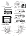
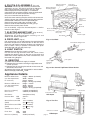
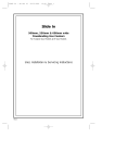
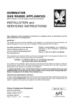
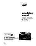
Please leave these instructions with the user
Baxi Bermuda GF3/LFE5 Super
Fireside Gas Central Heating Units
Installation and
Servicing Instructions
GF3 Super
LFE5 Super
Natural Gas
Propane Gas
Renewal
Baxi Bermuda GF3 Super
G.C.No. 37 077 59
Baxi Bermuda LFE5 Super
G.C.No. 37 077 61
Baxi Bermuda GF3 Super Propane
G.C.No. 37 077 69
Baxi Bermuda GF3 Super Renewal
G.C.No. 37 075 01A
Baxi Bermuda LFE5 Super Renewal
G.C.No. 37 075 03A
For use with the following boilers:
Baxi Bermuda 553 Propane
G.C.No. 44 077 75
For use with the following boiler:
Baxi Bermuda 45/4 M
G.C.No. 44 077 71
Baxi Bermuda 45/4 E
G.C.No. 44 077 73
Baxi Bermuda 57/4 M
G.C.No. 44 077 72
Baxi Bermuda 57/4 E
G.C.No. 44 077 74
Baxi Bermuda 51/5
G.C.No. 44 075 06
For use with the following boilers:
Baxi Bermuda 401
G.C.No. 44 077 49
Baxi Bermuda 552
G.C.No. 44 077 50
Baxi Bermuda 45/3 M
G.C.No. 44 077 61
Baxi Bermuda 45/3 E
G.C.No. 44 077 60
Baxi Bermuda 57/3 M
G.C.No. 44 077 63
Baxi Bermuda 57/3 E
G.C.No. 44 077 62
Baxi Bermuda 45/4 M
G.C.No. 44 077 71
Baxi Bermuda 45/4 E
G.C.No. 44 077 73
Baxi Bermuda 57/4 M
G.C.No. 44 077 72
Baxi Bermuda 57/4 E
G.C.No. 44 077 74
Baxi Bermuda 51/5
G.C.No. 44 075 06
Baxi is one of the leading manufacturers of domestic
heating products in the UK.
Our first priority is to give a high quality service to our
customers. Quality is built into every Baxi product products which fulfil the demands and needs of
customers, offering choice, efficiency and reliability.
To keep ahead of changing trends, we have made a
commitment to develop new ideas using the
latest technology - with the aim of continuing to
make the products that customers want to buy.
Everyone who works at Baxi has a commitment to
quality because we know that satisfied customers
mean continued success.
We hope you get a satisfactory service from Baxi. If
not, please let us know.
Baxi is a BS-EN ISO 9001
Accredited Company
page 2
Codes of Practice, most recent version
should be used
Information
In GB the following Codes of Practice apply:
Standard
Scope
BS 6891
Gas Installation.
BS 5546
Installation of hot water supplies for
domestic purposes.
BS 5871
Installation of gas fires, convectors and
fire/back boilers.
BS 5440 Part 1
Flues.
BS 5440 Part 2
Ventilation.
BS 6798
Installation of gas fired hot water boilers.
BS 5449 Part 1
Forced circulation hot water systems.
Safe Installation
The appliance is suitable only for installation in
GB and IE and should be installed in
accordance with the rules in force.
In GB, the installation must be carried out by a
CORGI Registered Installer. It must be carried
out in accordance with the relevant requirements
of the:
• Gas Safety (Installation & Use) Regulations.
• The appropriate Building Regulations either
The Building Regulations, The Building
Regulations (Scotland), Building Regulations
(Northern Ireland).
• The Water Fittings Regulations or Water
Byelaws in Scotland.
• The Current I.E.E. Wiring Regulations.
In IE the following Codes of Practice apply:
Standard
Scope
I.S. 813
Domestic Gas Installations.
The following BS standards give valuable additional information;
BS 5546
Installation of hot water supplies for
domestic purposes.
BS 5449 Part 1
Forced circulation hot water systems.
IMPORTANT - The addition of anything that may
interfere with the normal operation of the
appliance without express written permission
from the manufacturer or his agent could
invalidate the appliance warranty. In GB this
could also infringe the GAS SAFETY (Installation
and Use) REGULATIONS.
Where no specific instructions are given,
reference should be made to the relevant British
Standard Code of Practice.
In IE, the installation must be carried out by a
competent Person and installed in accordance
with the current edition of I.S. 813 ‘Domestic Gas
Installations’, the current Building Regulations
and reference should be made to the current
ETCI rules for electrical installation.
IMPORTANT - Installation, Commissioning,
Service & Repair
This appliance must be installed in accordance with
the manufacturer’s instructions and the regulations
in force. Read the instructions fully before installing
or using the appliance.
These Instructions must be read in conjunction
with those for the Boiler Section before
installing or using this appliance.
In GB, this must be carried out by a competent
person as stated in the Gas Safety (Installation &
Use) Regulations.
Definition of competence: A person who works for a
CORGI registered company and holding current
certificates in the relevant ACS modules, or valid
ACoP equivalents, is deemed competent.
In IE, this must be carried out by a competent
person as stated in I.S. 813 “Domestic Gas
Installations”.
page 3
Installation Instructions
These instructions must be read in conjunction with the
separate instructions for the boiler section
INTRODUCTION
This unit is the gas fire section of the Bermuda GF3 Super
or LFE5 Super central heating boiler and gas fire. The
heat input is 5.70kW (19,450 Btu/h) and the fire is
available for use with Gas Type G20 (Natural Gas) at
20mbar or Gas Type G31 (Propane). The fire is controlled
by a knob positioned on the right hand side of the case.
Ignition is by piezo spark to the pilot (Fig 13). For details
of the GF3 Super Propane appliance see page 15.
The control knob has six positions giving a choice of five
output rates.
POSITION
POSITION
POSITION
POSITION
POSITION
POSITION
1
2
3
4
-
THE FIRE IS OFF.
IGNITION/PILOT.
THE FIRE IS ON LOW.
THE FIRE IS ON MEDIUM.
THE FIRE IS ON MEDIUM/HIGH.
THE FIRE IS ON HIGH.
The artificial coal bed is illuminated by two concealed
lamps. These lamps are operated by a switch adjacent to
the control knob.
SITE REQUIREMENTS
The principal site requirements are determined by the
boiler but the following details are essential for the correct
installation of the fire:
Fireplace opening: (Fig.1)
Width
406mm (16in) MIN
584mm (23in) MAX
Height 560mm (22in)
Wherever possible always make the fireplace opening to
the maximum dimensions.
Hearth: If the fire is to be hearth mounted, the hearth
must be at least 13mm (1/2in) thick non-combustible material.
It must be at least 300mm (12in) (326mm (1213/16in) for GF3
Super) deep x 897mm (355/16in) wide, centrally placed about
the fireplace opening and at the same level as the base of
the builders opening. The top surface of the hearth should
be a minimum of 50mm (2in) above floor level and must be
level with the base of the opening. On no account should
the fire unit be fitted directly onto a combustible floor
or carpet.
Surround or Wall Finish: (Figs.1 and 2) The wall
behind the fire must be non-combustible. The surround or
wall finish must have a flat vertical area centrally placed
about the opening measuring a minimum of 789mm (31in)
high by 1015mm (405/64in) wide for LFE5 Super and 765mm
(301/8in) high by 765mm (301/8in) wide for GF3 Super. If a
surround is fitted any gaps between it and the wall must be
sealed and it must have a rating of 100oC or higher.
Wall Fixing: (Fig.2) The bottom of the fire must be
100mm (4in) to 125mm (5in) above the floor level.
It is strongly recommended that the fireplace opening is
made to the maximum dimensions.
The permanent vent may be directly into the room
containing the appliance. The vent may also be sited in
another room provided an interconnecting vent is used.
The vent must not be installed inside the builders opening.
The vent should be sited following good practice for a
habitable room.
We recommend the use of the stadium BM700 or BM701
ventilator which is available from your local merchant.
Important Information
This product contains Refractory Ceramic Fibres (R.C.F.)
which are man-made vitreous silicate fibres. Excessive
exposure to these materials may cause temporary
irritation to eyes, skin and respiratory tract. Care must be
taken when handling these articles to ensure the release
of dust or fibres is kept to a minimum.
To ensure that the release of fibres from these articles is
kept to a minimum, during installation and servicing it is
recommended that a H.E.P.A. filtered vacuum is used to
remove any dust, soot or other debris accumulated in and
around the appliance. This should be performed before
and after working on the installation.
It is recommended that any replaced item(s) are not
broken up but sealed within heavy duty polythene bags
and clearly labelled “R.C.F. waste”. This is not classified
as “hazardous waste” and may be disposed of at a tipping
site licensed for the disposal of industrial waste.
Protective clothing is not required when handling these
articles but it is recommended that gloves are worn and
the normal hygiene rules of not smoking, eating or
drinking in the work area are followed and always wash
hands before eating or drinking.
ELECTRICAL CONNECTIONS
The electrical supply to the fire is via a length of 3 core
cable with 3 pin socket provided. The cable must be
connected to the electrical plug and socket on the boiler
base (Fig.4). These connections should be made when
the boiler electrical connection is made as follows: (See
also Boiler Installation Instructions). The supply must be
230V 50Hz 110W.
Manual Controls Models
CONNECT THE BLUE WIRE TO THE TERMINAL MARKED 'N'.
CONNECT THE BROWN WIRE TO THE TERMINAL MARKED 'L2'.
CONNECT THE GREEN/YELLOW WIRE TO THE TERMINAL MARKED
.
Electronic Controls Models
CONNECT THE BLUE WIRE TO THE TERMINAL MARKED 'N'.
CONNECT THE BROWN WIRE TO THE TERMINAL MARKED 'L'.
CONNECT THE GREEN/YELLOW WIRE TO THE TERMINAL MARKED
.
NOTE: ON THE 51/5 BOILER THE FIRE EARTH IS CONNECTED TO THE
BOILER CHASSIS.
A permanent live must be fitted to the remaining terminal
in the socket marked 'L2' or 'L'. (See Boiler Instructions).
NOTE: Both the fire and the boiler must be supplied
by the same isolating switch.
4 core input cable for connection to the boiler unit must
NOT be less than 0.75mm 2 (24 x 0.2mm) PVC to
IEC53code 227 (heat resistant).
A shelf may be fitted above the fire provided that it is not
less than 76mm (3in) above the top of the fire and does
not exceed 230mm (9in) in depth. A minimum clearance
of 25mm (1in) at the left hand side and 76mm (3in) at the
right hand side must be catered for. The area between the
shelf and the top of the fire must be non-combustible.
Ventilation: Ventilation air supply should be in
accordance with the relevant standards. In GB this is BS
5440 Pt. 2. In IE this is I.S. 813 “Domestic Gas
Installations”. The permanent ventilation area size
requirements are:GF3/LFE5 & 45/4
69.075cm2 (10.7in2)
GF3/LFE5 & 57/4
89.685cm2 (13.9in2)
page 4
GF3/LFE5 & 51/5
75.45cm2 (11.7in2)
Illustrated Wiring Diagram
br
br
E
b
w
Switch
Bulb
Socket
br
Bulb
Socket
b
Resistor
w
Socket
from
Boiler
Functional
Flow Diagram
Bulbs
Switch
L E N
L
br
br
Resistor
N
GAS SUPPLY
1. The gas installation should be in accordance with
relevant standards. In GB this is BS 6891. In IE this is
I.S. 813 “ Domestic Gas Installations”. The gas supply is
provided from the service tap on the boiler unit. A supply
pipe is provided with the fire. This pipe has one flared end
for connection to the fire and a plain end which is
connected to the service tap by a nut and olive.
2. Dependent upon the position of the boiler relevant to
the surround or wall finish face, it may be necessary to
shorten the supply pipe. IF THE PIPE HAS TO BE
SHORTENED CARE MUST BE TAKEN. The length of the
supply pipe is determined as follows:
(a) Measure the distance 'D' from the centre of the front
positioning 'V' mark on the boiler tray, back to the
surround face or finished wall face (Fig.3).
(b) FROM THE PLAIN END of the supply pipe cut off a
length of pipe equal to the distance 'D' measured
above. Take care to ensure that the cut is square and
the pipe is free from burrs and swarf.
ALTERNATIVELY
(c) The amount of pipe required to be cut off can be
determined by holding the PLAIN END of the pipe
against the surround or finished wall face, marking the
pipe at the position of the centre of the front positioning
'V' mark on the boiler tray.
3. After threading the steel flare nut on the above pipe,
connect the plain end to the service tap with the remaining
nut and olive. It is important to ensure that the flared end
of the pipe:
(a) Faces to the right.
(b) Is parallel with the hearth or floor.
4. It is necessary to unscrew and remove the extension
plate from the boiler controls heat shield. Once removed
this item can be discarded (Fig.4).
GF3 Super
765mm (301/8in)
Min
LFE5 Super
789mm (31 in)
Min
Fireplace
Opening
560mm
(22in)
Hearth
Level
406-584mm
(16-23in)
GF3 Super 765mm (301/8in) Min
LFE5 Super 1015mm (405/64 in) Min
If the opening is being purposely prepared the maximum dimensions are
strongly recommended
Fig. 1 Fireplace Opening
560mm
(22in)
GF3 Super
765mm (301/8in)
Min
LFE5 Super
789mm (31 in)
Min
Fireplace
Opening
100-125mm
(4-5in)
Skirting Board
406-584mm
(16-23in)
GF3 Super 765mm (301/8in) Min
LFE5 Super 1015mm (405/64 in) Min
Maximum
dimensions are
strongly
recommended
Fig. 2 Wall Fixing
Surround Face or
Finished Wall Face
Fitting the Fire
HEARTH FIXING
Front "V" Mark
1. Fit the fire backing plate to the fire using the M5 x 8mm
thread forming screws provided (Fig.5).
2. Locate the fire spigot into the draught diverter on the
boiler. Push the fire backwards until the backing plate
touches the surround or finished wall face. Adjust the feet
to level the fire (Fig.6).
D
Gas Service Tap
Fig. 3 Gas Supply Pipe
3. Mark the position of the most suitable pair of securing
holes in the fire backing plate (Fig.5) and remove the fire.
Drill and plug the wall with suitable plugs. Replace the fire
and secure to the wall with suitable fixing screws.
4. Connect the supply pipe to the fire inlet connection.
WALL FIXING
1. Slide the fire support plate over the overhanging boiler
base (Fig.4). Using the screws provided, loosely attach
the plate using the slots at each side.
2. On electronic control boilers it will be necessary to
remove the input plug from the controls. Push the support
plate backwards until it touches the wall surface and
tighten the screws to lock the frame in position. Locate the
fire spigot into the draught diverter on the boiler. Push the
fire backwards until the backing plate touches the finished
wall face. Adjust the feet to level the fire (Fig.6).
3. Mark the position of the most suitable pair of securing
holes in the fire backing plate (Fig.5) and remove the fire.
Drill and plug the wall with suitable plugs. Replace the fire
and secure to the wall with suitable fixing screws.
4. Connect the gas supply pipe to the fire inlet connection.
page 5
Controls Heat
Shield
Extension
Panel
Gas Service
Tap
Fire Support
Plate
Fig. 4 Wall Fixing - Support Plate
Commissioning the Fire
12.Check the operation of the light effect by operating the
switch adjacent to the control tap (Fig.9).
1. Remove the polystyrene fitting securing the coal bed
(Fig.11) as follows:
(a) Disengage the front panel retaining clamps and
remove the glass front panel.
(b) Remove the polystyrene fitting securing the coal
bed.
(c) Carefully remove the coal bed from its plastic
bag.
CAUTION: The coal bed is extremely fragile and must
be handled accordingly. Gloves should be worn and
any inhalation of the dust should be avoided. Keep
the coals away from children at all times. Please read
the Important Information Section on page 3.
(d) Replace the coal bed and glass front panel.
13.Hand the user the User’s Instructions, explain the
operation of the boiler and fire and leave the unit set to
suit their requirements.
14.Leave these instructions with the user or adjacent to
the gas meter.
Location "Vee" Notches
Backing Plate
Alternative Fixing
Hole Position
2. Remove the pressure test point sealing screw and
connect a pressure gauge (Fig.6).
3. Turn on the gas service tap (at present supplying gas
to the boiler only) fully anti-clockwise. The service tap is
now supplying both the boiler and the fire (Fig.4).
GF3 Super
Backing Plate Securing
Screws (2 off)
Fig. 5 Backing Plate
Location "Vee" Notches
4. Purge according to in GB BS 6891 and in IE the
current edition of I.S. 813 “Domestic Gas Installations”.
Backing Plate
5. To light the fire pilot - fit the fire control knob, and
ensure that it is fully clockwise. Push in and turn anticlockwise past the positive stop at the pilot (
) position
to operate the igniter. Repeat until the pilot lights.
Continue to hold in the control knob for a further 15
seconds. Release slowly and the pilot should stay alight. If
the pilot does not stay alight turn the control knob to the
OFF position fully clockwise and repeat.
6. Check that the fire burner lights smoothly by pushing in
the knob and turning fully anti-clockwise. Test for gas
soundness with leak detection fluid.
LFE5 Super
Backing Plate Securing
Screws (2 off)
Fig. 5 Backing Plate
7. Check the fire pressure with the control knob in
position 4 fully anti-clockwise.The pressure should be
13.8mbar + 0.5mbar (5.5 in. wg. + 0.2 in. wg.) for LFE5
and 14.5mbar + 0.5mbar (5.8 in. wg. + 0.2 in. wg.) for GF3.
8. Turn the control knob clockwise to the OFF position
( ). Remove the pressure gauge and refit the pressure
test point sealing screw, ensuring a gas tight seal.
Fire Control
Tap
Outer Case
Securing Screws
(2 off)
9. Test for clearance of flue products as follows:
(a) Ensure that all doors and windows are closed.
IMPORTANT NOTE: If there is an extractor or
ceiling fan in the room or adjoining room then
the spillage test must be performed with the
fan turned on and any interconnecting doors
between the fan and the appliance left open.
(b) Turn on the fire (position 4 fully anti-clockwise).
(c) After 5 minutes take a smoke match and insert it
into the boiler draught diverter in the position
shown (Fig.8). If the majority of the smoke is not
drawn into the chimney spillage is indicated and
the fire must be operated for a further 10 minutes
before rechecking. If spillage is still evident the
cause must be ascertained and rectified before
continuing with commissioning.
(d) Repeat with both fire and boiler alight, having run
the boiler for 5 minutes.
Pressure Test Point
Sealing Screw
Adjusting Feet
(2 off)
GF3 Super
Outer Case
Fig. 6 Commissioning the Fire
Fire Control
Tap
Pressure Test
Point Sealing
Screw
10.Fit the case as follows:
(a) Remove the control knob.
(b) Lift the outercase over the heat exchanger and
locate the two 'vee' notches in the top of the case
into the 'vee' notches at the top of the inner case
(Fig.5).
(c) Secure the outercase to the inner case using the
two securing screws provided (Fig.6).
LFE5 Super
11.Plug in the electrical supply to the case and fit the
controls cover panel and control knob (Fig.13).
page 6
Outer Case
Securing Screws
(2 off)
Fig. 6 Commissioning the Fire
Adjusting Feet
(2 off)
Fire Flue Spigot
2.5mm - 4.0mm
Boiler Draught Diverter
End Baffle - Fire Flue Spigot
Fig. 7 Spark Gap
Fire Control
Knob & Light
Switch
Door - Boiler
Combustion Box
Smoke Match
Position
Fire
Boiler
Fig. 8 Spillage Test
Pilot Viewing Window
Indicator Light
Thermostat Knob
Service Tap
Electronic Controls Boiler 51/5
Fire Data Label
Levelling Screws
Pilot Viewing Window
Service Tap
Fig. 9 Outer Case - GF3 SUPER
Fire Control
Knob & Light
Switch
Service Tap
Pilot Indicator Light
Boiler Lockout Light
Thermostat Knob
Electronic Controls Boiler
Pilot Viewing Window
Service Tap
Igniter Button
Fire Data Label
Thermostat Knob
Levelling Screws
Service Tap
Grey Push Button
Manual Controls Boiler
Fig. 9 Outer Case - LFE5 SUPER
Control Tap
Securing Locknut
Burner
Injectors
(2 off)
Tap Fixing Bracket
Thermocouple
Spark Electrode
Lead
Burner Injectors
(2 off)
Fire Control Tap
Spark Electrode
Lead
Thermocouple
Pressure Test Point
Sealing Screw
Fig. 10 The Controls - GF3 SUPER
Fig. 10 The Controls - LFE5 SUPER
page 7
Pressure Test Point
Sealing Screw
Servicing the Fire
Changing Components
CAUTION: ISOLATE THE ELECTRICAL SUPPLY
INCLUDING THE PERMANENT LIVE. TURN OFF THE
GAS SUPPLY, ENSURE THAT THE FIRE IS COLD,
TEST FOR GAS SOUNDNESS UPON RE-ASSEMBLY.
Please read the Important Information Section on page 4.
Instructions 1-17 are for servicing to be carried out
annually and should be followed in conjunction with the
separate instructions for the boiler section.
1. Remove the controls cover panel under the front of the
fire by grasping it firmly by its edges and pulling forwards.
2. Disconnect the 3 pin plug from the socket under the
fire.
3. Remove the outercase as follows:
(i) Pull off the control tap knob.
(ii) Remove the 2 outercase securing screws (Fig.6).
(iii) Remove the case by easing the lower edge
forward and then lifting upward.
4. Turn off the gas service tap by turning fully clockwise
(Fig.4).
5. Disconnect the fire supply pipe from the fire inlet and
remove the 2 screws securing the backing plate to the
inner case. Pull the fire forward until the fire spigot is clear
of the boiler canopy and lift away.
6. Remove the glass front panel as follows: (Fig.11).
(i) Ensure that the glass front panel is cold.
(ii) Disengage the front panel retaining clamps and
remove the glass front panel.
7. Remove the coal bed by carefully lifting it away from
the locating pins (Fig.11).
CAUTION: The coal bed is extremely fragile and must
be handled accordingly. Gloves should be worn and
any inhalation of the dust should be avoided. Keep
the coals away from children at all times.
8. Remove the burner as follows : (Figs.10 and 11).
(i) Disconnect the compression nuts from the
injectors.
(ii) Remove the 2 screws securing the burner, and
remove the burner out over the support bar.
(iii) Using a soft brush remove all deposits from
the top of the burner and the burner ports.
9. Remove and clean or replace the injectors as
necessary. Do not use a pin or wire for cleaning
purposes.
10.Clean any lint or debris from the pilot aeration hole.
Inspect the pilot, thermocouple and electrode assembly
for deterioration and replace if necessary. No adjustment
of the A.S.D. pilot assembly is possible. The A.S.D.
should not be altered to prevent it operating correctly or
bypassed in any way.
If the A.S.D. has to be replaced only use a Genuine Baxi
Spare Part.
11.Replace the parts in reverse order of dismantling,
making sure that:
(i) Spark gap is as in Fig.7.
(ii) The coal bed is correctly fitted over its locating
pins.
(iii) The glass front panel sealing rope is replaced if it
is in anyway damaged.
(iv) The glass front panel is replaced if it is in anyway
damaged or cracked. NOTE: THIS IS A HEAT
RESISTANT GLASS AND MUST NOT BE
REPLACED BY ORDINARY GLASS
12.After servicing the boiler, fit the fire to the boiler and
refit the screws securing the fire backing plate to the inner
case. Connect the fire supply pipe to the inlet adaptor.
13.Turn the service tap ON by turning fully anti-clockwise
(gas to boiler and fire). Check for gas soundness.
14.Temporarily fit the control knob and light the fire.
Check that the gas pressure is correct. (See
“Commissioning the Fire”).
15.Test for clearance of flue products as described:
in paragraph 9 of “Commissioning the Fire”.
16.Refit the outercase, control knob, 3 pin plug, case
securing screws and controls cover plate.
17.Re-check that the ignition is satisfactory.
CAUTION: ISOLATE THE ELECTRICAL SUPPLY
INCLUDING THE PERMANENT LIVE, TURN OFF THE
GAS SUPPLY, ENSURE THAT THE FIRE IS COLD,
AFTER REPLACING ANY COMPONENTS ALWAYS
TEST FOR GAS SOUNDNESS.
Please read the Important Information Section on page 4.
Replace all components in the reverse order of
dismantling. If necessary re-light the boiler pilot.
Remove the outercase and turn off the gas service tap
as described in 1 - 4 of 'Servicing the Fire'.
The following components can be removed as described
below:
1. GAS CONTROL TAP / FFD /
PILOT FILTER (Fig.12)
(a) To grease the tap proceed as follows: Pull off the
plastic cap and disconnect the spark electrode lead from
the piezo unit. Undo the two screws and washers
securing the niting plate to the tap body. Remove the
piezo unit complete with the gas tap spindle and spring.
Now remove the plug and apply a suitable grease
sparingly (excessive grease may block the gasways).
On re-assembling care must be taken to ensure that both
the plug and spring are in place.
(b) To exchange the component: (Fig. 10). Pull off the
plastic cap and disconnect the spark electrode lead from
the piezo unit. Disconnect the four pipes at the gas tap.
Disconnect the thermocouple from the gas tap. Remove
the 3 screws securing the gas tap bracket to the inner
case and remove the complete assembly (LFE5 only).
Remove the locknut holding the gas tap to the bracket or
innercase and remove the gas tap. Ensure that the pilot
filter supplied with the new tap is fitted.
On re-assembly ensure that the spark electrode lead is
correctly fitted and that the plastic cap is pushed on to the
piezo unit.
2. GLASS FRONT PANEL (Fig.11)
(a) Ensure that the glass front panel is cold.
(b) Disengage the front panel retaining clamps and
remove the glass front panel.
NOTE: THIS IS A HEAT RESISTANT GLASS AND
MUST NOT BE REPLACED BY ORDINARY GLASS
On re-assembly ensure that:
The glass front panel sealing rope is replaced if it is
in anyway damaged.
3. SEALING ROPE (Glass Front Panel) (Fig.11)
Remove the glass front panel as described above.
Carefully pull off the sealing rope from the retaining barbs
on the combustion chamber. On re-assembly ensure that
the sealing rope is securely fitted onto the retaining barbs.
4. COAL BED (Fig.11)
Remove the glass front panel as described above.
Remove the coal bed by carefully lifting it away from the
locating pins. On re-assembly ensure that the coal bed is
correctly located over the locating pins.
CAUTION: The coal bed is extremely fragile and must
be handled accordingly. Gloves should be worn and
any inhalation of the dust should be avoided. Keep
the coals away from children at all times.
5. BURNER (Figs.10 & 11)
(a) Remove the glass front and coal bed as described
above.
(b) Disconnect the compression nuts from the injectors
and remove the injectors.
(c) Remove the two screws securing the burner and draw
the burner out over the support bar.
page 8
6. PILOT/A.S.D. ASSEMBLY (Fig. 12a)
WARNING: The A.S.D. pilot assembly should not be
adjusted in any way. The A.S.D. shall not be altered so
that it will not operate or bypassed in any way. The
thermocouple cannot be changed as an individual
component.The complete assembly must be replaced in
the event of one or other component failure(s).
Only use a Genuine Baxi Spare Part.
Glass Front Panel
Sealing Rope
Rope Seal
Retaining Barbs
Glass Front Panel
Retaining Clamps
Undo the screw retaining the pilot shield, and remove the
shield. Pull back the sleeve and disconnect the lead from
the electrode. Undo the nut on the pilot feed pipe.
Remove the screw holding the assembly to the
bracket. Undo the thermocouple from the gas tap.
Remove the assembly from the fire.
On re-assembly, shape the thermocouple in a similar
manner to the original.
7. ELECTRO-MAGNET UNIT (Figs 10 & 12)
(a) Remove the gas tap as explained in 1(b).
(b) Remove the electro-magnet retaining nut and
withdraw the electro-magnet unit.
8. PIEZO UNIT (Fig.12)
Glass Front
Panel
Support Bar
Spark
Electrode
Burner Securing
Screws (2 off)
Coal Bed Locating
Pins (2 off)
Pilot &
Thermocouple
Pilot Shield
Fig. 11 Coal Bed
Pull off the plastic cap and disconnect the spark electrode
lead from the piezo unit. Undo the tabs on the rear of the
piezo unit and remove. Replace the piezo unit twisting the
tabs to retain it firmly in position. Re-connect the spark
electrode lead and re-fit the plastic cap.
F.F.D./Electro-Magnet Unit
Gas Tap Body
with Plug
9. LIGHT SWITCH
Caution: Ensure electrical supply is isolated.
Pull off the two flag terminals from the switch. Press
together the retaining arms on the rear of the switch and
remove the switch. Replace the switch and terminals, see
illustrated wiring diagram.
10. RESISTOR
(a) Check that the electrical supply is isolated.
(b) Remove the two screws securing the light bulb cover
and lift upwards.
(c) Remove the clip securing the resistor to the cover and
disconnect the 2 wires.
(d) Replace the resistor and reassemble in reverse order.
Electrical Supply 230V 50Hz 110W.
Igniter
Retaining
Screws
Piezo Igniter
Fig. 12 Gas Control Tap/Flame Failure Device
Appliance Details
BERMUDA GF3 SUPER
(see Site Requirements
for clearances)
BERMUDA LFE5 SUPER
(see Site Requirements
for clearances)
Height - 706mm (to hearth)
Width - 750mm
Depth - 326mm
Weight - 35.8kg (unpacked)
Height - 713mm
Width - 915mm
Depth - 301mm
Weight - 39.1kg (unpacked)
HEAT INPUT (GROSS)
HEAT OUTPUT
5.70kW (19,450 Btu/h)
3.69kW (12,590 Btu/h)
GAS GROUP
G20 (Natural Gas)
INJECTOR SIZE
GF3
LFE5
SETTING PRESSURE LFE5
(Cold)
230 F11
F13
14.5 + 0.5mbar
(5.8 + 0.2in wg)
13.8 + 0.5mbar
(5.5 + 0.2in wg)
THERMOCOUPLE OUTPUT
9.4 - 13mV
PILOT ASSY
9402
9401
210W (715 Btu/h)
SETTING PRESSURE GF3
(Cold)
GF3
LFE5
HEAT INPUT (GROSS)
Fig. 12a
Gas Control
Knob
Controls Cover Panel
GF3 Super
Fig. 13 The Fire
Controls Cover Panel
page 9
LFE5 Super
Gas Control
Knob
Fault Finding Chart
BAXI BERMUDA GF3 SUPER & LFE5 SUPER
Gas Type G20 (Natural Gas)
YES
Does the
pilot ignite ?
START
Turn on gas
supply
NO
Is
there a
spark at the
electrode ?
NO
Is
gas supply
turned on ?
YES
Adjust spark gap
NO
NO
Is
spark gap
2.5 to 4mm ?
YES
Is
spark
igniter
working ?
YES
Clean pilot burner
NO
YES
NO
Check electrode
lead & insulation
Replace
piezo igniter
Is
supply
pressure correct ?
(20mb working)
YES
Is
pilot burner
clean ?
NO
YES
Consult the
gas supplier
2.5mm - 4.0mm
NO
Change pilot filter
Has
new pilot filter
been fitted ?
YES
Spark Gap
Change pilot
assembly
NO
Is
poor flue
pull, downdraught
or blockage evident, or
flue otherwise
unsound?
YES
The thermocouple cannot be changed
as an individual component.The
complete assembly must be replaced
in the event of one or other component
failure(s).
Only use a Genuine Baxi Spare Part.
Rectify flue
page 10
YES
Do
both bulbs
light ?
Does
the fire remain
alight ?
Fire satisfactory
NO
NO
Are
gas cocks fully
open ?
YES
NO
Open gas cocks
Does one
bulb light?
YES
Replace faulty bulb
YES
NO
Is
meter pressure
correct ?
NO
Contact the Gas
Supplier
Are bulbs
switched on ?
NO
Switch on bulbs
YES
Is
supply
pressure at
appliance
correct ?
NO
NO
Pipework
undersized or
restricted
YES
Are
pilot flames
stable and approx
20mm long ?
Is
lead
from mains
connected ?
YES
Is
thermocouple
tip
clean ?
NO
Is there
230V
across light
switch ?
NO
Change pilot
assembly
Is there
230V across
resistor ?
NO
Make good the
connection
YES
YES
Is
thermocouple
output
within limits ?
(9.4 - 13mV)
NO
Change pilot
assembly
Replace both
bulbs
YES
Is flue
blocked causing
A.S.D. to
operate ?
YES
Rectify flue
NO
Change the electro
magnetic unit
page 11
NO
Replace light switch
YES
YES
Is
thermocouple
connection
sound ?
Connect
lead
YES
Clean
thermocouple tip
YES
Is
thermocouple
tip
sound ?
NO
NO
Change resistor
Short Parts List
88/89
78
72/75
89/90
53/55
83/84
82
83/85
94/95
79/100
97/98
90/91
BAXI BERMUDA LFE5 SUPER
B.G.C. No 37 077 61
Key No
BAXI BERMUDA GF3 SUPER
B.G.C. No 37 077 59
Description
G.C.
No
Manufact'rs
Part No
53
Seal - Glass Frame
155 747
043111
72
Glass & Frame Assembly
155 758
78
Knob - Gas Tap Control
82
Description
G.C.
No
Manufact'rs
Part No
55
Seal - Glass Frame
155 747
043111
040955
75
Glass & Frame Assembly
155 758
040955
E01-160
237879
78
Knob - Gas Tap Control
156 431
234551
Flame Failure Device/Gas Tap
Concentric TE/SA 2324
82
378 916
238966
Flame Failure Device/Gas Tap
Concentric TE/SA 2324
378 916
238966
Encapsulated Unit
Concentric TE/418
83
Piezo Unit
393 734
042941
384 248
082462
85
84
Piezo Unit
393 734
042941
Encapsulated Unit
Concentric TE/418
384 248
082462
89
Injector - F13
381 879
238543
88
Injector - 230 F11
381 879
092133
90
Burner - Aeromatic
Baxi Special
89
155 949
043210
Burner - Aeromatic
Baxi Special
155 949
043210
97
Coal Bed
156 429
235149
94
Lead - Electrode
378 915
236199
95
Lead - Electrode
E01-138
237813
98
Coal Bed
156 429
235149
91
Pilot / A.S.D.
278 912
235601
90
Pilot / A.S.D.
378 914
236204
79
Pilot Filter
205 723
082412
100
Pilot Filter
205 723
082412
83
Key No
page 12
Renewal Firefront
Boiler Modification
It is important that the existing installation is correct and
that the flue is performing satisfactorily. Any remedial
work necessary should be completed before the new
appliance is commissioned. Please read the Important
Information Section on page 4.
BERMUDA 401 & 552
Adhesive Foil Label
New Controls
Heat Shield
WARNING: When a renewal firefront is installed with a
Bermuda 401, 552, 45/3 or 57/3 which does not have
an Atmospheric Sensing Device fitted the combined
appliance will not shut down under adverse flue
conditions. (When the fire is used without the boiler
on, the Atmospheric Sensing Device will operate).
NOTE: A permanent live is required for correct operation
of the firefront.
Additional Installation Instructions
Bermuda GF3 Super Renewal G.C.No 37 075 01A
Bermuda LFE5 Super Renewal G.C.No 37 075 03A
The kit supplied with Renewal appliances provides all the
necessary components to fit a Baxi Bermuda GF3 Super
Renewal & Baxi Bermuda LFE5 Super Renewal firefront
to the following Bermuda Boilers.
The Renewal Fires may be used with the following
Boilers:
Bermuda 401
Bermuda 552
Bermuda 45/3 M
Bermuda 45/3 E
Bermuda 57/3 M
Bermuda 57/3 E
Bermuda 45/4 M
Bermuda 45/4 E
Bermuda 57/4 M
Bermuda 57/4 E
Bermuda 51/5
G.C.No 44 077 49
G.C.No 44 077 50
G.C.No 44 077 61
G.C.No 44 077 60
G.C.No 44 077 63
G.C.No 44 077 62
G.C.No 44 077 71
G.C.No 44 077 73
G.C.No 44 077 72
G.C.No 44 077 74
G.C.No 44 075 06
Controls Heat
Shield
NOTE: It is important at this stage to fit the
controls heat shield supplied with the fire unit to
the boiler front panel.
Remove and discard the controls heat shield
provided with the boiler and fit the new controls heat
shield using the screws previously removed.
Check the data badge on the back boiler. If the boiler
internal wiring is not depicted, take the foil label from
the kit and attach it below the data badge on the
boiler front door.
Existing Fire
BERMUDA 45/3 & 57/3, 45/4, 57/4 & 51/5
REMOVING THE EXISTING FIRE
Isolate the gas and electrical supply, including any
permanent live, to the combined appliance.
Remove the controls cover panel from the front of the fire.
Remove the tap control knob. Disconnect the electrical
socket from the fire plug if fitted. Remove the screws
securing the outercase to the innercase. Lift off the
outercase.
Turn the gas service tap to the "Boiler only" position by
turning 1/4 turn clockwise.
Extension Plate
Remove the radiants if fitted.
Disconnect the supply pipe at the fire inlet.
Bermuda 57/3 Illustrated
Remove any screws securing the fire to the wall. Pull the
fire forward until the flue spigot is clear of the boiler hood
and lift away.
Remove and discard the fire supply pipe from the service
gas tap. Disconnect and discard any electrical wiring
between the boiler input terminal and the fire.
page 13
If a radiant firefront has been installed previously it
will be necessary to unscrew and remove the
extension plate from the boiler controls heat shield.
Once removed this item can be discarded.
If the fire is wall mounted remove and discard the existing
support frame (Bermuda 401 only). Retain the two
support brackets. These will be needed in wall mounting
the renewal fire.
If the fire is hearth mounted ensure that the base of the
builders opening and the front hearth are at the same
level.
Refer to "Site Requirements" (page 4) and prepare the
wall surface to the dimensions described.
Fire Support Plate - Bermuda 401 & 552
WALL FIXING
Two wall fixing plates are supplied in the Renewal Kit,
one for Bermuda 401/552 and one for Bermuda 45/3,
57/3, 45/4, 57/4 & 51/5
.
BERMUDA 401 & 552
Take the fire support plate from the fire unit packaging
and loosely attach it beneath the boiler base protruding
from the fireplace opening using the M5 Nuts and screws
provided. Use the centre group of holes at each side.
Fire Support Plate - Bermuda 45/3 & 57/3, 45/4, 57/4 & 51/5
NOTE: If the fire is being used with a Bermuda 401 boiler
unit, the support brackets from the previous plate must be
fitted before the fire support plate can be fixed in place.
Push the support plate backwards until it touches the
surround or wall face and tighten the screws to lock it in
position.
Support
Brackets
(401 Only)
BERMUDA 45/3 & 57/3, 45/4, 57/4 & 51/5
Take the fire support plate from the fire unit packaging
and loosely attach it above the boiler base protruding
from the fireplace opening using the screws provided.
Use the slots at each side.
Push the support plate backwards until it touches the
surround or wall face and tighten the screws to lock it in
position.
BERMUDA 401 & 552
Fire Support
Plate
WIRING
When connecting the firefront wire to the plug on the
boiler base tray refer to page 4 of these instructions.
FIRE SUPPLY PIPE
Two fire supply pipes are supplied in the Renewal Kit, one
for Bermuda 401 & 552 and one for Bermuda 45/3 & 57/3,
45/4, 57/4 & 51/5. The smaller (6mm) diameter one is for
Bermuda 45/3 & 57/3, 45/4, 57/4 & 51/5 installations.
TO CONTINUE FITTING THE FIREFRONT REFER TO
THE INSTALLATION CHAPTER OF THESE
INSTRUCTIONS.
Bermuda 57/4 Illustrated
Fire Support
Plate
BERMUDA 45/3 & 57/3, 45/4, 57/4 & 51/5
page 14
Propane Cat ll 2H3P
Supplementary Instructions
The following spares components differ from Natural Gas
models.
BERMUDA GF3 SUPER PROPANE
G.C.No 37 077 69
Bermuda GF3 Super Propane
Description
G.C.No
Manufact'rs
Part No
Flame Failure Device/Gas Tap
Concentric TE/SA 2632
E01-143
237100
Injector - Fire Propane - P 100
378 856
092089
Burner - Aeromatic - Propane
E01-145
237209
A.S.D. Assembly
E01-152
237810
Coal Bed - Propane
E01-144
237221
Pin Coal Bed Locating/Burner Securing
156 097
092125
GAS TYPE G31
This section details the differences between Natural
Gas and Propane models.
Propane firefronts are only suitable for use with
Bermuda 553 Propane Back Boiler appliances. The
instructions supplied with the back boiler contain details
of gas supply requirements and electrical connections.
All site requirements and installation details can be
found earlier in this booklet.
NOTE: When removing the burner it is necessary to
remove the right hand retaining screw and the left
hand coal bed retaining pin which also retains the
burner.
Bermuda GF3 Super Propane
Heat Input (Gross)
Gas Group
Injector Marking
Supply Pressure
Setting Pressure (Cold)
5.64kW (19,243 Btu/h)
G31 (Propane)
P 100
37.0mbar
14.8in wg
35.0 + 1.7mbar
14.0 + 0.7in wg
Propane appliances can be converted to operate on
Natural Gas if required.
A conversion kit is available, Baxi Part No 247064.
page 15
BAXI POTTERTON
Brownedge Road Bamber Bridge Preston Lancashire PR5 6SN
After Sales Service 08706 096 096 Technical Enquiries 08706 049 049
www.baxi.co.uk
Comp No 237607 - Iss 7 - 1/03