1
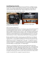
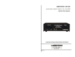
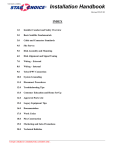
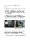
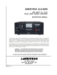
Review: The “New” Ameritron ALS-600 600-Watt HF Power Amplifier
Phil Salas – AD5X
Introduction
The compact and light-weight ALS-600 solid-state amplifier has been around for many
years. Using four Motorola MRF-150 TMOS FETs operating at 50 volts, the ALS-600
provides 600 watts PEP SSB, 500 watts CW typical output power from 160-10 meters. It
is simple to use (no tuning required), effective (only 4dB down from full legal limit), and
reasonably priced. Internal protection circuits automatically protect the ALS-600 from
improper operation, high SWR, or high heat-sink temperature. The ALC interface can be
customized for any transceiver through a rear-panel adjustment control. Finally, accurate
cross-needle meters read SWR/Peak Power on the amplifier, and voltage/current on the
power supply. Now while the ALS-600 provides your basic amplifier features, new
solid-state amplifiers on the market are offering additional features that many hams want.
The “new” ALS-600 Amplifier
Ameritron’s solution to the competition has been to quietly evolve the ALS-600 with
small changes so options can be added for those who want them, while keeping the basic
amplifier cost low for those who don’t need the additional features. First, Ameritron
introduced a switching power supply option. As the ALS-600 consists of separate
amplifier and power supply units, you can easily select either the less expensive linear
power supply or the light-weight switching power supply. The switching power supply is
1/3rd the weight of the linear power supply, making it attractive for portable operation.
The most recent change to the ALS-600 (Serial Numbers 14378 and higher) adds remote
control and automatic transceiver band-change capability using either the ALS-500RC
Remote Control Head, or the ARI-500 Automatic Band Switch – or both! These units
were originally designed for use with the ALS-500M mobile amplifier, as this mobile
amplifier is normally mounted remotely from the transceiver. Now these units also
interface with the ALS-600 via a pair of amplifier front panel RJ45 jacks. ALS-600
amplifiers with lower serial numbers can be factory upgraded. Contact Ameritron for
pricing. So - let’s take a look at each of these new optional control units.
Photo A: RJ45 jacks (upper right) provide
optional remote control capability.
Photo B: New relay-switched low pass
filter board permits remote band switching.
ALS-500RC Remote Control Head
The ALS-500RC allows you to remotely mount your ALS-600, yet still have access to
the amplifier’s frequency switch and fault reset function (via the ALS-500RC POWER
switch). It also provides amplifier RF output power monitoring, and DC PWR, TX
(transmit) and O/L (fault/overload) LEDs. Anyone looking at your station will not
realize that you have a 600 watt amplifier available!
Compact ALS-500RC provides all
ALS-600 control and monitoring.
600 watts out & no amp in sight!
ARI-500 Automatic Band Switch
The ARI-500 automatically selects the correct frequency range for the ALS-600 amplifier
by reading band data from the transceiver. A pair of supplied 6-foot CAT-5 cables
provides amplifier interfacing, and a 6-foot CAT-5 cable terminated with an RJ45 on one
end is provided for making a transceiver interface cable. The manual provides detailed
information so you can connectorize this cable for popular Icom, Kenwood, and Yaesu
transceivers, the Elecraft K3 transceiver, and other equivalent transceivers. If you don’t
want to build your own cable, Ameritron has pre-built cables for many popular radios.
Besides controlling the amplifier’s frequency range, the ARI-500 has some additional
desirable features. A low current-drive amplifier keying interface does away with the
requirement for an external buffer for all transceivers. It even works with the low-drive
HSEND output from the IC-706MKIIG and IC-7000 radios. The ARI-500 can also be
strapped to automatically clear an amplifier bypass fault so you don’t have to manually
reset your ALS-600. I’ve found this convenient as I get frequent ALS-600 SWR faults
from birds landing on my high-Q MFJ-1775 rotatable dipole!
If desired, you can plug the ALS-500RC Remote Control Head into the ARI-500 to
remotely display ALS-600 RF output power and RX and O/L status. When plugged into
the ARI-500, the ALS-500RC automatically defeats the ARI-500 auto-reset feature since
the ALS-500RC provides manual STANDBY/OPERATE switching at your fingertips.
In my opinion, the ALS-500RC is very convenient when the ARI-500 is not used and the
ALS-600 is remotely located. However, I don’t really see the need for it when you have
an ARI-500, and the ARI-500 is strapped for automatic fault reset.
Let’s Fire-Up the ALS-600 with all the options
The ALS-600 power supply comes wired for 120VAC operation so it is ready to plug
into your wall outlet. However, you should plug the amplifier into a separate AC branch
than the one your transceiver is connected to unless you have a 20-amp AC branch circuit
(transceivers typically draw 3-4 amps, and the ALS-600 typically draws 11-14 amps).
Connect a ground wire from the amplifier to your station’s single-point ground, and an
ALC cable between the ALS-600 and your transceiver. Finally, connect the two RJ45
cables between the ARI-500 and the ALS-600, the RJ45 cable between the ALS-500RC
and the ARI-500, and the transceiver interface cable between your transceiver and the
ARI-500. Both the ALS-500RC and the ARI-500 are powered through the ALS-600
RJ45 interface cables, so no external DC voltage is required.
The only set-up required is to set the ALS-600 band switch to REMOTE, and strap the
ARI-500 for either auto- or manual fault re-set. There is also a strapping option in the
ARI-500 to enable 10/12 meter operation if the ALS-600 is equipped with the optional
10/12 meter MOD10-MB kit. Once you turn on your ALS-600 and transceiver, the
POWER and LINK LEDs on the ARI-500 will glow, indicating everything is connected
properly and data is being received from your transceiver.
ARI-500 on author’s transceiver.
If used, the ALS-500RC.plugs into
REMOTE A on the ARI-500.
Amplifier interface cables connect
to these ports on the rear of the ARI-500.
While the ALS-500RC is very convenient for manual remote control of the ALS-600, the
real “cat’s meow” is the ARI-500 Automatic Band Switch. It is very nice to change
bands on my transceiver and have the amplifier follow. I really like this, especially since
I’ve forgotten to manually change bands on my “old” ALS-600 more times than I’d care
to admit – especially in the heat of a contest or trying to snag that rare DX. Fortunately
the amplifier’s fault circuitry always protects the amplifier, as it has when I’ve
accidentally transmitted into disconnected or shorted antenna runs! I should be more
careful, but I have been spoiled by the effectiveness of the protection circuits.
Performance Measurement
I ran some basic performance measurements to check amplifier power and power meter
accuracy using an external PowerMaster digital peak-hold wattmeter. For the peak SSB
readings, I found that sending “dits” at about 10 WPM gave me similar readings as when
using a long peak-hold wattmeter setting on voice while saying “hellooooo test one two
three four”. I adjusted the transmitter drive while sending “dits” until the peak reading
was 600 watts, or the maximum output the amplifier was capable of if I couldn’t get 600
watts out. Then I measured the key-down power and drive levels necessary to achieve
this. As Table 1 shows, the “new” ALS-600 does a good job meeting its typical power
output specifications. I also found the ALS-600 peak-reading wattmeter to be quite
accurate – within my ability to read the amplifier’s analog meter. I really couldn’t see
any difference between the ALS-600 power meter and the external digital power meter.
TABLE 1: Amplifier Power Output Measurements (external digital wattmeter)
Band Drive
Key Dwn
Peak SSB
160M 85 watts
500 watts
600 watts
80M 95 watts
480 watts
525 watts
40M 95 watts
500 watts
600 watts
20M 90 watts
500 watts
600 watts
17M 85 watts
500 watts
600 watts
15M 95 watts
500 watts
600 watts
12M 85 watts
500 watts
600 watts
10M 95 watts
500 watts
580 watts
I also verified that the SWR protection shutdown occurs at 75 watts reflected power,
corresponding to an SWR of 2.1:1 at 600 watts. Since the amplifier protects itself at an
absolute value of 75 watts reflected power, operating into a higher SWR is possible by
simply reducing your output power. But you really should address the high SWR issue.
Alas – Nothing is Perfect
You need to be aware that the ALS-500RC Remote Control Head loads the ALS-600 RF
Power Meter, resulting in a half-power reading on the amplifier’s power meter. This is
not considered a problem by Ameritron, as the ALS-500RC is normally used when the
ALS-600 is remotely mounted and so the power meter isn’t readily visible. This is
discussed in both the ALS-600 and ALS-500RC manuals.
While the ARI-500 is a great addition to the ALS-600, there are a few things that would
improve its functionality. First, the ARI-500 could be made more convenient for remote
monitoring of your ALS-600. While you can use the ALS-500RC to provide amplifier
status, it would be nice if the ARI-500 had TX and O/L indicator LEDs so you could
monitor the amplifier’s status directly on an ARI-500 located at your operating position.
Next, the ARI-500 automatically puts your ALS-600 in OPERATE whenever your
transceiver is keyed, regardless of the OPERATE/STANDBY switch position on the
ALS-600. So you must turn the amplifier power off if you want to check your drive level
or operate your transceiver bare-foot. Therefore, an OPERATE/STANDBY switch
mounted on the ARI-500 would also be nice.
In order to address these issues, I built a very simple interface that plugs into the ARI500. See the supplemental article below for details.
Conclusion
The compact Ameritron ALS-600 solid-state amplifier Ameritron, now with remote
control and automatic band changing options, is a very affordable unit with pricing and
features that let it fit many budgets and operating locations.
Note: The ALS-600 QSK modification discussed in the “Modifications” section of this
web site is applicable to this new version of the ALS-600, as well as the older ALS-600.
Supplemental Article – Control/Indicator Unit for the ARI-500
As discussed above, there are no ALS-600 status indicators on the ARI-500, and you
must switch your ALS-600 off to run bare-foot or check exciter drive power.
To remedy these “deficiencies”, I built a compact interface that plugs into the ARI-500
REMOTE A input that includes PWR, TX and O/L LEDs, and a STANDBY/OPERATE
switch. The circuit is shown in Figure 1. While I made my own RJ45 cable interface,
I’ve called out an RJ45 cable so you can just cut off the necessary cable length. The
cable length is non-critical, but it should extend just 3” from the box to the end of the
RJ45 connector if you want to mount the interface unit right on the ARI-500. All parts
(Table 1) are from All Electronics (www.allelectronics.com). The photos show the
internal wiring of the interface unit unit, and the unit mounted on the ARI-500 with
double-sided tape. Labeling was done using Casio “White-on-Clear” labeling tape.
J1-8
J1-1
1N4007
O/L (Red)
1 2 3 4 5 6 7 8
PWR (Grn)
J1-7
STBY
4.7K
J1-3/4
OPR
RJ45 Panel (Socket) View
4.7K
J1-2
TX (Yel)
Figure 1: ARI-500 Interface Unit Schematic
Wiring of ARI-500 Interface Unit.
Interface Unit on ARI-500.
Note: The last photo shows a highly modified ARI-500 that is the subject of another
article.
In order to use this interface unit, strap the ARI-500 as though the ALS-500RC is being
used. Unlike the ALS-500RC however, this interface unit does not disable the ARI-500
auto-reset, nor does it load the ALS-600 RF power meter. Now I can mount the ALS-600
out of the way and still monitor TX and O/L status. And I can easily switch between
OPERATE and STANDBY so I can check transceiver drive or switch between barefoot
and full-power operation.
Table 1 – ARI-500 Interface Unit parts list. All Electronics part numbers shown.
QTY
1
1
1
1
2
1
1
1
Description
Subminiature toggle switch
Ultra-bright green LED
Ultra-bright red LED
Ultra-bright yellow LED
4.7K ¼-watt resistor
1N4007
2.36x1.36x0.8” plastic box
3-ft CAT5 cable
Part Number
SMTS-4
LED-57
LED-94
LED-72
4.7K-1/4
1N4007
1551-HBK
CB-53
Price ea.
$1.35
$2.00
$0.55
$0.95
5/$0.50
6/$1.00
$1.95
$2.35