1
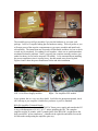
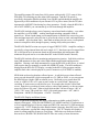
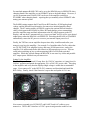
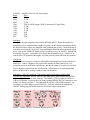
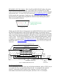
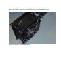
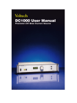
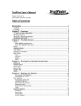
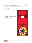
Review: The Elecraft KPA500 500-Watt HF Power Amplifier
Phil Salas – AD5X
Introduction
A recent entry into the solid-state amplifier market is the Elecraft KPA500, a 160-6 meter
500 watt solid-state amplifier with auto-band switching and silent PIN-diode T/R
switching. The KPA500 is a rugged, attractive and compact solid-state amplifier with an
internal micro-processor controlling the amplifier, metering and displays, and protection.
It includes an internal highly efficient linear power supply making the KPA500 ideal for
home, portable and DX operations. The KPA500 is available factory built and tested, or
as a no-solder kit. The unit reviewed here is the KPA500-K no-solder kit.
Figure 1: Elecraft KPA500 in operation on 6-meters
First we have to build it!
The KPA500 kit is much less complex than the K3. And like the K3, P3, and W2 kits the
assembly process requires only basic mechanical skills. The Assembly Manual can be
downloaded from www.elecraft.com for review prior to ordering. The KPA500 kit
arrived in a small 15” x 15” x 13” box containing four fully assembled and tested circuit
assemblies (control/display card, power supply module, I/O module, and PA assembly)
and an assortment of cabinet pieces and hardware. See Figures 2 and 3.
Figure 2: KPA500-K arrives!
Figure 3: Kit sub-assemblies
The assembly process will go smoothly if you sort the hardware as you open each
package. I used a 12-cupcake baking pan for hardware sorting. This was perfect as you
will empty most of the cupcake compartments as you open, assemble and install each
sub-assembly. The instructions are clear and well illustrated, and there is a box to check
as each step is completed. Everything fit well together – there was no confusion and no
mechanical tolerance problems. Once I got going, the complete assembly took me just
under four hours (it was hard to stop once I’d started). I was concerned about installing
the power transformer since it is pretty heavy, but this turned out to be no big deal.
Figures 4 and 5 show the power transformer before and after installation.
Figure 4: Ready for the power transformer. Figure 5: Now all we need is the front panel.
Left - I/O & Power Supply modules.
Right – The Amplifier/LPF module
In my opinion, this is a very easy kit to build. Just follow the instruction manual, check
off each step as you complete it, and before you know it you’ll be finished!
KPA500 Amplifier Technical Details
The KPA500 includes an internal 120/240VAC linear power supply and matches the K3
in size with dimensions of 4.5x11.3x11.7 inches including the fan. The complete
amplifier weighs 26 pounds, with 13-pounds (half) of the KPA500’s weight due to the
hefty toroidal AC power transformer. A handle on the right side and rubber feet on the
left side makes transporting the amplifier quite easy.
The amplifier outputs 500 watts from 160-6 meters with typically 25-35 watts of drive.
PIN-diode T/R switching provides silent QSK operation. And the T/R switch is
specifically designed to handle switching even with RF applied should the amplifier be
bypassed by a fault condition or by an external ATU or power meter (like the W2) that
interrupts the AMP KEY line during key-down operation. Finally, when the KPA500 is
off or in STANDBY, you can transmit up to 200 watts through the amplifier.
The KPA500 includes always-active frequency sensed auto band-switching – even when
the amplifier is in STANDBY – making auto band-switching compatible with all
transceivers. When a band change occurs amplification is disabled, the correct low-passfilter and input network is selected, time is given for the relays to settle, and amplification
is re-enabled – all in less than 30ms. Auto band-switching can also occur via an optional
transceiver/amplifier cable, though frequency sensing always takes precedence.
The KPA500 final RF section uses a pair of rugged VRF2933 FETs. Amplifier cooling is
provided by a large internal heat sink and a single 4-1/2” fan whose speed is stepped from
off- to full-speed in six increments based on the internal heat-sink temperature (the
minimum fan speed can be set to other than OFF in the KPA500 menu if desired).
The KPA500 includes effective monitoring and protection circuitry. Soft faults switch an
input 3dB attenuator in-line, and critical faults inhibit amplification and bypass the
amplifier. Clearing a soft fault automatically reverts the KPA500 to full power. A critical
fault requires that you manually re-enable the OPERATE mode. The fault condition is
displayed on the KPA500 TFT display, recorded in the KPA Utility program, and the
amplifier fault code is also displayed on your K3 transceiver (if AUXBUS is enabled).
SWR faults are based on absolute reflected power. A soft fault occurs when reflected
power exceeds about 60W which corresponds to a 2:1 SWR at 500W, so you can operate
the KPA500 into a higher SWR at reduced power. Reflected power greater than 100
watts, or a SWR of 18:1 at 25 watts or more results in a critical fault. Input power
exceeding 45 watts causes a soft fault for up to 10 seconds after which a critical fault
occurs. Input drive exceeding 60 watts causes a critical fault instantly, as does an output
power level above 650 watts. Other critical faults include Vdd out of range (<40V or
>90V), 270V error (T/R switch bias <200V), Heat sink temperature > 90C, and PA
Dissipation > 600W (PA Dissipation = Pin DC - Pout RF).
The KPA500 Display and Menu System
There is significant monitoring and display information available on the KPA500’s
attractive front panel. LEDs provide OPERATE, STANDBY and FAULT indications as
well as bargraph displays for power output and SWR (700 watts and 5:1 SWR maximum,
respectively). A TFT display provides detailed menus, frequency band, RF power, SWR,
and PA temperature, current and voltage information. The TFT display also displays a
menu for setting amplifier features to your liking. While there are numerous features
that can be set, BAND CHG, RADIO and TR Time are worthy of some discussion.
For matched antennas BAND CHG can be set so the KPA500 stays in OPERATE when
changing bands if the amplifier was in OPERATE prior to the band change. However, if
you use an antenna tuner, BAND CHG can be set so the amplifier switches to
STANDBY when changing bands – requiring that you manually select OPERATE after
tuning your antenna system.
The RADIO setting supports the K3 and Yaesu BCD interface, ICOM analog band
voltage, and the Kenwood serial interface for transceiver-initiated amplifier band
changes. The K3 setting enables AUXBUS (requires the optional Elecraft interface
cable), which permits the KPA500 to follow K3 band changes prior to transmitting,
provides amplifier status and fault information to the K3 (which appears on the K3
display), and sets the K3 automatically to a “power-per-band” drive level for your desired
output power when the KPA500 is in OPERATE. Switching the KPA500 to STANDBY
automatically causes the K3 power to revert to your normal output power level.
Finally, the TR Time sets an amplifier drop-out time delay in milliseconds after your
transceiver un-keys the amplifier. For example I’ve found that older TenTec radios that
use TX EN/TX KEY for amplifier keying, and some ICOM transceivers, un-key the
amplifier 5-10 milliseconds before the transceiver RF output decays to zero. This can
result in hot-switching on key-up when operating QSK in a PIN diode-switched
amplifier. While this will not damage the KPA500, it can cause key-clicks and possible
ALC output power fold-back on your transceiver.
Setting Up the Amplifier
The first thing to do is to install 12-amp fuses for 120VAC operation, or 6-amp fuses for
240VAC operation and attach the appropriate 120- or 240-VAC power cable. Then plug
in the amplifier and verify that the displayed high-voltage is within the recommended
range. Next connect a PC to the RS232 (PC) connector and download and install the
KPA Utility. Finally, check if the firmware is up-to-date and update it if it is not.
Figure 6: Rear panel of the KPA500
Next connect a ground wire, RF IN/OUT and PA KEY and ALC cables to your
transceiver. The PA KEY interface is 5VDC open circuit/ground-to-enable at 1ma
making it compatible with all transceivers with no need for a special interface. ALC is
not mandatory, but if used, adjust your drive level for normal KPA500 output power and
set the ALC to kick-in just above this power level.
For K3 transceivers the optional KPAK3AUX package includes a 3-foot cable that
provides band data, AUXBUS, amp-keying and ALC connections. Also included in the
KPAK3AUX package is a HD15 splitter cable for connecting other accessories to the K3
accessory connector, and a M/F HD15 “port saver” with pin 10 missing so external
equipment can disable the KPA500 by interrupting an external amp-keying cable.
Performance Measurements
Table 1 summarizes the measurements made in the ARRL lab.
Table 1: Elecraft KPA500 SN218 Technical Data
Manufacturer's Specifications
Measured in ARRL Lab
Frequency Range: All ham bands
As specified.
from 1.8-54 MHz.
Power output: 500 W.
As specified.
Driving power required: 30 to 40 W.
As specified.
Spurious and harmonic suppression: not HF, –51 dBc, worst case¹; typically –55 to
Specified.
–60 dBc; 50 MHz, –60 dBc; Meets FCC
requirements.
Third order IMD:
3rd/5th/7th/9th: 34/53/46/54 dB below PEP
not specified.
(14 MHz, 500 W PEP output).
Primary power requirements: 100–125,
Transmit; 980 W maximum; standby, 14 W;
200-250 V ac.
standby with fan (low speed), 18 W;
standby with fan (high speed), 24 W at
117 VAC.
¹160 meters, at maximum output.
The KPA500 power digital power meter and bargraph display can be precisely calibrated
per-band if you have an accurate wattmeter. Simply select the desired band and adjust
the KPA500 menu PWR ADJ setting so the digital power reading tracks the external
watt-meter (the 500-watt bargraph LED just lights at the 500-watt level when the
KPA500 digital wattmeter is properly calibrated). I checked the KPA500 digital power
meter against my NIST-traceable calibrated Array Solutions PowerMaster wattmeter and
found the worst-case default KPA500 digital wattmeter readings to be within 3%. As the
PowerMaster spec is +/- 3%, I’m not sure that calibrating the KPA500 wattmeter really
bought me anything other than consistency between the two wattmeter readings!
The KPA500 easily outputs a consistently steady 500 watts, indicating the PA
components are not pressed to the maximum. As a matter of fact, I could drive the
amplifier well above 500 watts output on all bands. This is not recommended of course,
as IMD performance and reliability will suffer at higher power. As Table 2 shows, the
KPA500 typically requires just 25-35 watts of drive for full output. Low drive power
also means that your transceiver should be operating at a much lower IMD point.
TABLE 2: Amplifier Drive for 500 watts Output
Band
Drive
160M
27W
80M
25.5W
40M
33.5W
30M
12W for 190W output (200W is maximum US legal limit)
20M
35.5W
17M
31.5W
15M
31.5W
12M
26W
10M
24W
6M
32W
Operating
I really like the tight integration between the KPA500 and K3. When the amplifier is
turned on or off, or switched from standby to operate, the K3 display momentarily shows
the KPA500 status (as does any amplifier fault condition that occurs). And not having to
remember to reset the K3 drive level when enabling the KPA500 makes operation stupidproof. Just tap the OPERATE button and you instantly have a 500-watt K3! And the fan
is normally very quiet. I sometimes even forget that the amplifier is on. Finally, as an
almost 100% CW operator I thoroughly enjoy the perfectly silent full break-in operation.
Conclusion
The KPA500 is a compact, well-protected amplifier that integrates perfectly with the K3
transceiver – and to a slightly lesser extent with virtually all other transceivers. It is
reasonably priced as solid-state amplifiers go, and the no-solder kit is quite easy to build.
If your amplifier requirements are satisfied with a 7dB increase over normal operating
power, the KPA500 is certainly worthy of your consideration.
Addendum: 240VAC operation, Cable options and a fan mounting modification
US 240VAC Operation: For US 240VAC you must specify the Elecraft PWR-US240, a
NEMA 6-15P power cable when ordering. The NEMA 6-15P fits either the NEMA 615R or 6-20R outlet. However there are many standard NEMA 240VAC connectors used
in the US as shown in Figure 7. For other than the NEMA 15R or 20R receptacle, you
can simply cut off the plug on your KPA500 AC cord and substitute the appropriate
240VAC mating plug purchased from your local home improvement store.
Figure 7: NEMA 240VAC connectors popular in the US.
KPA500/K3 AUX Cable Options: The 3-foot Elecraft KPAK3AUX cable is fine when
the KPA500 is placed next to your K3. For a longer cable, a modified SVGA cable
works well, but you MUST verify that all SVGA 15-pins are properly connected through
(often not the case). A 6-foot SVGA M/F cable from www.cablewholesale.com (10H101206) satisfies this requirement. Modify the cable by breaking off the pins shown in
Figure 8 below by grasping the pin against the connector body with long-nose pliers.
Then twist and pull out the pin.
1
X
6
X
2
7
X
11
3
10
X
9
8
X
12
5
4
13
14
15
X: Break off pin 10 if you
wish to use an external PTT
RCA-type cable
Figure 8: HD15M
pin-side view
I built a special cable (Figure 9) that permits my modified MFJ-998 auto-tuner to disable
the KPA500 during tuning via the KPA500 amp-inhibit input. No separate amp-key
cables are needed from my K3 through the MFJ-998 to the KPA500, and the amp disable
input is much faster than interrupting the AMP-KEY line due to the MFJ-998 relay speed
(<1ms vs 5ms). The MFJ-998 modification is in the “Equipment Modifications” section
of this website. A 10-conductor shielded cable (10CS22) and a RCA cable (ACB-6 cut
to length) were purchased from www.allelectronics.com. The DB15HD connectors and
hoods came from www.mouser.com (male 156-1815-E, female 156-1915-E, hoods 1562009-EX).
Shield – Drain wire soldered to DB15HD M/F shells
AUXBUS
Band1
2
1
6
11
9
8
7
12
KPA500-side:
HD15F
Solder-pin
view
4
3
13
Gnd
5
10
14
15
PTT/Key
Band2
ALC
5
4
10
15
3
9
14
Band3
Band0
Gnd
2
8
13
1
7
12
6
11
K3-side:
HD15M
Solder-pin
view
Amp Inhibit
(MFJ-998)
Amp Inhibit
10-conductor
shielded cable
Figure 9: KPA500/K3/MFJ-998 AUX cable
1.5-ft RCA
shielded cable
Fan Mounting Modification
The fan mounting screws don’t have any real locking mechanism, and it is VERY easy to
over-tighten the screws and possibly damage the fan. As I wanted the fan mounted
securely, I replaced the four 2-inch #6 screws with four 6-32x1/2" screws/splitlockwashers to attach the fan to the back panel, and four 6-32x1/2" screws/split-
lockwashers and 6-32 nuts to attach the finger guard to the fan (see Figure 10). An
angled-in #1 Phillips screwdriver easily tightens the back panel fan mounting screws.
Figure 10: Alternate fan mounting method