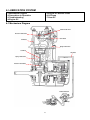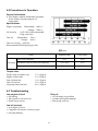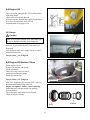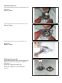
1
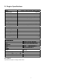
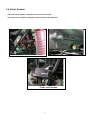
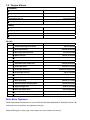
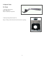
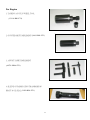
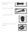
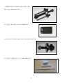
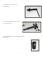
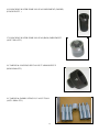
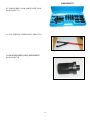
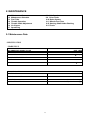
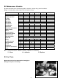
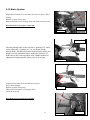
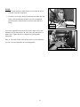
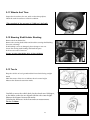
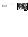
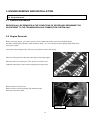
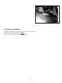
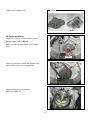
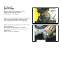
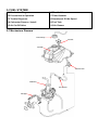
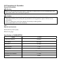
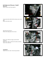
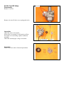
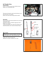
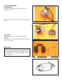
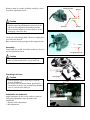
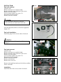
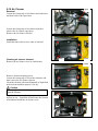
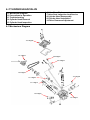
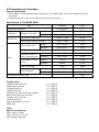
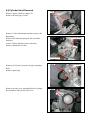
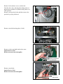
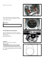
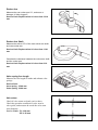
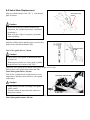
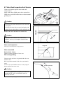
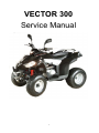
VECTOR 300
Service Manual
1
Contents
1. INFORMATION
1-1 Safety
1-2 Notes
1-3 Engine Specifications
1-4 Serial Number
1-5 Torque Values
1-6 Special Tools
2. MAINTENANCE
2-1 Maintenance Data
2-2 Maintenance Schedule
2-3 Fuel Tube
2-4 Throttle Operation
2-5 Throttle Cable Adjustment
2-6 Air Cleaner
2-7 Spark Plug
2-8 Idle Speed
2-9 Drive Chain
2-10 Brake System
2-11 Wheels And Tires
2-12 Steering Shaft Holder Bushing
2-13 Toe-In
3. ENGINE REMOVE AND INSTALLATION
3-1 General Information
3-2 Engine Removal
3-3 Engine Installation
4. LUBRICATION SYSTEM
4-1 Mechanism Diagram
4-2 Precautions In Operation
4-3 Troubleshooting
4-4 Engine Oil
4-5 Engine Oil Strainer Clean
4-6 Oil Pump
4-7 Gear Oil
5. FUEL SYSTEM
5-1 Mechanism Diagram
5-2 Precautions In Operation
5-3 Trouble Diagnosis
5-4 Carburetor Remove / Install
5-5 Air Cut-Off Valve
5-6 Throttle Valve
5-7 Float Chamber
5-8 Adjustment Of Idle Speed
5-9 Fuel Tank
5-10 Air Cleaner
6. CYLINDER HEAD/VALVE
6-1 Mechanism Diagram
6-2 Precautions In Operation
6-3 Troubleshooting
6-4 Cylinder Head Removal
6-5 Cylinder Head Inspection
6-6 Valve Stem Replacement
6-7 Valve Seat Inspection And Service
6-8 Cylinder Head Reassembly
6-9 Cylinder Head Installation
6-10 Valve Clearance Adjustment
7. CYLINDER/PISTON
7-1
7-2
7-3
7-4
7-5
7-6
7-7
Mechanism Diagram
Precautions In Operation
Trouble Diagnosis
Cylinder And Piston Removal
Piston Ring Installation
Piston Installation
Cylinder Installation
8. V-BELT DRIVING SYSTEM
8-1
8-2
8-3
8-4
8-5
8-6
8-7
Mechanism Diagram
Maintenance Description
Trouble Diagnosis
Left Crankcase Cover
Drive Belt
Drive Face
Clutch Outer/Driven Pulley
9. FINAL DRIVING MECHANISM
9-1
9-2
9-3
9-4
9-5
9-6
9-7
Mechanism Diagram - Transmission Cover
Precautions In Operation
Trouble Diagnosis
Disassembly Of Transmission
Inspection Of Mission Mechanism
Bearing Replacement
Re-assembly Of Final Driving Mechanism
10. ALTERNATOR/STARTING CLUTCH
10-1 Mechanism Diagram
10-2 Precautions In Operation
10-3 Right Crankcase Cover Removal
10-4 A.C.G. Set Removal
10-5 Right Cover Bearing
10-6 Flywheel Removal
10-7 Starting Clutch
10-8 Flywheel Installation
10-9 A.C.G. Set Installation
10-10 Right Crankcase Cover Installation
11. CRANKCASE / CRANK
11-1 Mechanism Diagram
11-2 General Information
11-3 Trouble Diagnosis
11-4 Disassembly Of Crankcase
11-5 Crankshaft Inspection
11-6 Assembly Of Crankcase
12. COOLING SYSTEM
12-1
12-2
12-3
12-4
12-5
12-6
12-7
12-8
Mechanism Diagram
General Information
Trouble Diagnosis
Trouble Diagnosis For Cooling System
System Test
Radiator
Water Pump
Thermostat
13. STEERING AND SUSPENSION
13-1
13-2
13-3
13-4
13-5
Parts Drawing
Troubleshooting
Handlebar
Throttle Housing
Steering System
14. FRONT WHEEL AND BRAKE SYSTEM
14-1
14-2
14-3
14-4
14-5
Parts Drawing
Troubleshooting
Front Wheels
Hydraulic Brake
Suspension Adjustment
15. REAR WHEEL AND BRAKE SYSTEM
15-1
15-2
15-3
15-4
15-5
Parts Drawing
Troubleshooting
Remove Rear Wheel And Rear Brake
Swingarm & Rear Axle Holder
Suspension Adjustment
16. FENDERS AND EXHAUST PIPE
16-1
16-2
16-3
16-4
Fenders Drawing
Rear Fenders Removal
Front Fender Removal
Exhaust Pipe Removal
17. ELECTRICAL SYSTEM
17-1 Troubleshooting
17-2 Ignition Coil
17-3 Ignition Timing
17-4 Battery Information
17-5 Electric Starter
17-6 Light Bulbs Replacement
17-7 Instrument Pane
17-8 Wiring Diagram
18.TROUBLESHOOTING
18-1 Engine Can Not Work
18-2 Poor Performance At Low And Idle Speeds
18-3 Poor Performance At High Speed
18-4 Loss Power
18-5 Poor Handling
1. INFORMATION
1-1
1-2
1-3
Safety
Notes
Engine Specifications
1-4
1-5
1-6
Serial Number
Torque Values
Special Tools
1-1 Safety
GASOLINE
Gasoline is extremely flammable and is explosive under certain condition.
Do not smoke or allow sparks or flames in your work area.
ϥ CARBON MONOXIDE
Never run the engine in a closed area. The exhaust contains poisonous carbon
monoxide gas that may cause loss of consciousness and lead to death.
ϥ BATTERY ELECTROLYTE
The battery electrolyte contains sulfuric acid. Protect your eyes, skin and
clothing. If you contact it, flush thoroughly with water and call a doctor if electrolyte
gets in your eyes.
ϥʳ HOT PARTS
Engine and exhaust pipe become very hot and remain hot for one hour after the
engine is run. Wear insulated gloves before handling these parts.
ϥʳ USED ENGINE/GEAR OIL
Used engine oil and gear oil may cause skin disease if repeatedly contact with
the skin for long periods.
Keep out of reach of children.
1-2 Notes
All information, illustrations, directions and specifications included in this publication are base on the latest
product information available at the time of approval for printing.
JI-EE Dynamic Technology Industry Co., Ltd. reserves the right to make changes at any time without notice and
without incurring any obligation whatever.
No part of this publication may be reproduced without written permission.
6
1-3 Engine Specifications
Type
Displacement
Bore and Stroke
Compression
Maximum Hp
Maximum Torque
Carburetor
Ignition
Starting
Lubrication
Transmission
4 StrokeΔSingle Cylinder, Water cooled
287.2c.c.
75 mm x 65 mm
10.0:1
20ps / 6500
(Nm/rpm) 24.6 Nm / 5000
DC-CDI
Electric
Auto oil injection
Automatic (C.V.T. V-belt + Reverse)
CHASSIS
Overall Length
Overall Width
Overall Height
Wheel base
Ground Clearance
Dry Weight
Fuel Tank Capacity
1815mm
1062mm
1130mm
1193mm
150mm
225Kg
12L
SUSPENSION
Front
Rear
Double A-Arm & Adjustable
Swing Arm & Adjustable Shock
BRAKES
Front
Rear
Front
Hydraulic Disc*2
Rear Hydraulic Disc*1
TIRES
Front
Rear
21x7-10
22x10-10
PRESSUREμ psi ( kgf/cm2)ν
Front
Rear
12(0.8)
12(0.8)
COLORING
Specifications subject to change without notice.
7
1-4 Serial Number
The frame serial number is stamped on the front of the frame.
The engine serial number is stamped on the left side of the crankcase.
Frame serial number
8
1-5 Torque Values
STANDARD
ϥ 5 mm bolt and nut
5 N.m (3.5 lbf.ft)
ϥ 6 mm bolt and nut
10 N.m (7.2 lbf.ft)
ϥ 8 mm bolt and nut
22 N.m (16 lbf.ft)
ϥ10 mm bolt and nut
35 N.m (25 lbf.ft)
ϥ12 mm bolt and nut
55 N.m (40 lbf.ft)
ENGINE
ϥ Cylinder head nut
38 N.m (27.4 lbf.ft)
ϥ Spark plug
12 N.m (8.9 lbf.ft)
ϥ Cylinder head bolt
15 N.m (10.1 lbf.ft)
ϥ Alternator bolt
8 N.m (5.9 lbf.ft)
FRAME
ϥ Handlebar upper holder bolt
24 N.m (17.7 lbf.ft)
ϥ Throttle housing cover screw
4 N.m (2.9 lbf.ft)
ϥ Steering shaft nut
50 N.m (36.9 lbf.ft)
ϥ Steering shaft holder bolt
33 N.m (24 lbf.ft)
ϥ Wheel rim bolt
18 N.m (13.3 lbf.ft)
ϥ Tie rod lock nut
35 N.m (25.8 lbf.ft)
ϥ King pin nut
40 N.m (29 lbf.ft)
ϥ Handlebar lower holder nut
40 N.m (29.5 lbf.ft)
ϥ Front wheel bolt
24 N.m (17.7 lbf.ft)
ϥ Front axle castle nut
40-60 N.m (30-45 lbf.ft)
ϥ Front brake arm nut
4 N.m (3.0 lbf.ft)
ϥ Rear brake arm nut
7 N.m (5.2 lbf.ft)
ϥ Rear axle castle nut
40-60 N.m (30-45 lbf.ft)
ϥ Rear wheel bolt
24 N.m (17.7 lbf.ft)
ϥ Exhaust muffler mounting bolt
30 N.m (22.1 lbf.ft)
ϥ Engine hanger bolt
30 N.m ( 22 lbf.ft)
ϥ Rear axle holder bolt
90 N.m (65 lbf.ft)
ϥ Swing arm pivot nut
90 N.m (65 lbf.ft)
ϥ Rear shock absorber mounting nut
45 N.m (33 lbf.ft)
Nuts, Bolts Tightness
Perform periodical maintenance in accord with the Periodical Maintenance Schedule Check if all
bolts and nuts on the frame are tightened securely.
Check all fixing pins, snap rings, hose clamp, and wire holders for security.
1-6 Special Tools
For Frame
1. Adjustable Hook Spencer
(E1105-LRA0-FT1)
Purpose: Adjusting of suspension
2. Ball Joint Puller(E0205-LRA0-FT1)
Purpose: Taking out the ball joint from front knuckle as repairing.
10
For Engine
˄ˁʳ˧˔˖˞˜ˡ˚ʳ˔˖˚ʳ˙˟ˬʳ˪˛˘˘˟ʳ˧ˢˢ˟ʳ
ʻC1110-RB1-FT1)ʳ ʳ ʳ ʳ
ʳ
ʳ
ʳ
˅ˁʳ˖ˢ˨ˡ˧˘˥ʳ˦˛˜˙˧ʳ˜ˠˣ˟˘ˠ˘ˡ˧ʳʻI1003-RB1-FT1)ʳ
ʳ
ʳ
ʳ
ʳ
ʳ
ˆˁʳ˔˗˝˨˦˧ʳ˧˔ˣˣ˘˧ʳ˜ˠˣ˟˘ˠ˘ˡ˧ʳ
ʻA4721-HMA-FT1) ʳ
ʳ
ʳ
ʳ
ʳ
ˇˁʳ˦˟˘˘˩˘ʳˢ˙ʳ˙˔˕˥˜˖˔˧˜ˡ˚ʳ˧˥˔ˡ˦ˠ˜˦˦˜ˢˡʳ
˦˛˔˙˧ʳʹʳˢ˜˟ʳ˦˘˔˟ʳʻI1202-RB1-FT1)ʳ
ʳ
ʳ
ʳ
ʳ
11
ˈˁʳ˦˟˘˘˩˘ʳˢ˙ʳ˙˔˕˥˜˖˔˧˜ˡ˚ʳ˟ʳ˖˥˔ˡ˞ʳʹʳˢ˜˟ʳ
˦˘˔˟ʳʻI1201-HMA-FT1)ʳ
ʳ
ʳ
ˉˁʳ˧˔˞˜ˡ˚ʳˉ˅˃ˈʳ˕˥˚ˁʳ˧ˢˢ˟ʳʻI6150-6205-FT1)ʳ
ʳ
ʳ
ʳ
ʳ
ˊˁʳˉ˅˃ˈʳ˕˥˚ˁʳ˞ˡˢ˖˞ʳ˧ˢˢ˟ʳʻI6150-6205-FT2)ʳ
ʳ
ʳ
ʳ
ʳ
ʳ
ʳ
ˋˁʳ˟ʳ˖˥˔ˡ˞ʳ˖˔˦˘ʳ˖ˢ˩˘˥ʳ ʳ ˉ˃˃ˉʳ˕˥˚ˁʳ˙˔˕˥˜˖˔˧˜ˡ˚ʳ˧ˢˢ˟ʳ
ʻI6150-6006-FT1ʼʳ
ʳ
ʳ
ʳ
ʳ
ʳ
ʳ
12
ˌˁʳ˙˔˕˥˜˖˔˧˜ˡ˚ʳ˥ʳ˖˥˔ˡ˞ʳ˖˔˦˘ʳ˖ˢ˩˘˥ʳ ʳ ˉ˅˃˄ʳ
˕˥˚ˁʳ˧ˢˢ˟ʳʻI6140-6201-FT1ʼʳ
ʳ
10.ʳ˧˔˞˜ˡ˚ʳ˕˥˚ˁʳ˥˕˄ʳ˧ˢˢ˟ʳʻI6150-RB1-FT1ʼʳ
ʳ
ʳ
ʳ
ʳ
˄˄ˁʳˣˡ˘˨ˠ˔˧˜˖ʳ˧˔˞˜ˡ˚ʳ˕˥˚ˁʳˉ˅˃ˈʳ˧ˢˢ˟ʳʻI6150-6205-FT3ʼʳ
ʳ
12. ˧˔˞˜ˡ˚ʳ˧˔ˣˣ˘˧ʳˣ˜ˡʳ˧ˢˢ˟ʳʻA4451-HMA-FT1ʼ
13
ġ
13. łŔŔņŎŃōŊŏňġŅœŊŗņġŔʼnłŇŕġŕŐŐōġ
ĩB3411-RB1-FT1Īġ
ġ
ġ
ġ
ġ
ġ
ġ
ġ
ġ
ġ
ġ
ġ
ġ
ġ
ġ
ġ
ġ
ġ
ġ
ġ
14. ŕłŌŊŏňġŕœłŏŔŎŊŔŔŊŐŏġŔʼnłŇŕġŃœňįġķĴıĶġ
ġ
ŕŐŐōġĩI6100-6305-FT1Īġ
ġ
ġ
ġ
ġ
ġ
ġ
ġ
ġ
ġ
ġ
ġ
ġ
ġ
15. KNOCKING BRG.(6901) WATER PUMP IMPLEMENT
(I1001-KJ9-FT1)
14
16. KNOCKING WATER PUMP OIL SEAL IMPLEMENT (INSIDE)
(I1205-KF0-FT1 )
17. KNOCKING WATER PUMP OIL SEAL(IRON) IMPLEMENT
(A9217-H9A-FT1)
18. TAKING & LOCKING SPECIAL NUT 36MM SLEEVE
(I0202-HMA-FT1)
19. TAKING & FABRICATING IN. VALVE TOOL
(A4711-HMA-FT1)
15
20. TAKING BRG. 62040 LARGE-SIZE TOOL
(I6100-6204-FT3 )
21. ALL-PURPOSE FIXER (B2101-HMA-FT1)
22. KNOCKING BRG.(6204) IMPLEMENT
(I6100-6204-FT2)
16
2. MAINTENANCE
2-1
2-2
2-3
2-4
2-5
2-6
2-7
Maintenance Data
Maintenance Schedule
Fuel Tube
Throttle Operation
Throttle Cable Adjustment
Air Cleaner
Spark Plug
2-8 Idle Speed
2-9 Drive Chain
2-10 Brake System
2-11 Wheels And Tires
2-12 Steering Shaft Holder Bushing
2-13 Toe-In
2-1 Maintenance Data
SPECIFICATION
SPARK PLUG
SPARK PLUG GAP
0.8 mm
RECOMMENDED SPARK PLUGS
THROTTLE LEVER FREE PLAY
IDLE SPEED
NGK CR8E
5-10 mm
1700̈́100 rpm
BRAKE LEVER FREE PLAY
15-25 mm
DRIVE CHAIN SLACK
10-25 mm
TOE-IN
5̈́10 mm
TORQUE VALUES
SPARK PLUG
12-19 N.m
TIE-ROD LOCK NUT
35-43 N.m
ENGINE OIL
1.4 Liter (1.2Liter for change)
GEAR LUBRICATION OIL
750cc (650cc for change)
17
2-2 Maintenance Schedule
The internal maintenance in the following table is based on average riding, normal conditions.
Riding in unusually dusty areas, require more frequent servicing.
Fuel Lines
Throttle Operation
Air Filter
Fuel Filter
Spark Plug
Drive Chain
Brake Shoes
Brake System
Brake Fluid
Nuts, Bolts & Fasteners
WHEEL/TIRES
Wheels
Steering System
Suspension System
C.V.T Drive belt
Transmission Oil
Engine Oil
Battery
Oil Filter (Screen)
Valve Clearance
Coolant
Cooling Fan
Carburetor (Idle Speed)
Choke
300KM
1 Month
I
I
I
I
I, L
I
I
I
I
I
I
I
R
R
I
C
I
I
I
I
I
Every
Every
3 Months 6 Months
I
I
C
R
I
Every
1 Year
Every
2 Years
R
R
R
Lubricate for every 1 month
I
I
R
I
I
I
I
I
R
Replace for every 3,000km or 6 Months
Replace for every 3,000km or 6 Months
I,C
I,C
C
I
I
R
I
I
Note – I: Inspect and Clean, Adjust, Lubricate or Replace, if necessary
C: Clean
L: Lubricate
R: Replace
2-3 Fuel Tube
Inspect the fuel lines for deterioration, damaging or
leakage and replace if necessary.
18
Notes
2-4 Throttle Operation
Inspect for smooth throttle lever full opening and automatic
full closing in all steering positions.
Inspect if there is no deterioration, damage or kink in the
throttle cable, replace it if necessary.
Check the throttle lever, free play is 5-10 mm at the tip of the
throttle lever.
Disconnect the throttle cable at the upper end.
Lubricate the cable with commercially lubricant to prevent
premature wear.
2-5 Throttle Cable Adjustment
Slide the rubber cap of the adjuster off the throttle
Housing, loosen the lock nut and adjust the free play
of the throttle lever by turning the adjuster on the throttle housing.
Inspect the free play of the throttle lever.
2-6 Air Cleaner
Please remove the four hooks, and then disassemble
two screws inside the air cleaner case.
Pull out the air filter element from the air cleaner case.
Washing the element in non-flammable solvent, squeeze
out the solvent thoroughly.
Let it dry.
Soak the filter element in gear oil and then squeeze
out the excess oil.
Install the every component into air cleaner in the reverse order of
removal.
Note: for more detail please check chapter 5-10
2-7 Spark Plug
This spark plug is located at the front of the engine.
Disconnect the spark plug cap and unscrew the spark plug.
Check the condition of spark plug electrodes wear.
19
Throttle
Change a new spark plug if the electrodes and insulator tip appear unusually fouled or burned.
Discard the spark plug if there is apparent wear or if the insulator is cracked or chipped.
The spark plug gap shall keep in 0.8mm
With the sealing washer attached, thread the spark plug in by hand to prevent crosses threading.
Tighten the spark plug with 1.0~1.2kgf-m
2-8 Idle Speed
Connect an engine speed meter.
Warm up the engine, 10 minutes are enough.
Turn the idle-speed adjust screw on the carburetor to obtain the idle speed. “Turn in” (clockwise) will
get higher speed. “Turn out” (counter clockwise) will get lower speed.
IDLE SPEED: 1700±100 rpm
2-9 Drive Chain
Stopping the ATV and shift the transmission into neutral(N) .
Measure the drive chain slack midway between the
sprockets.
Chain slack =15~25mm (5/8~1 inch)
Adjust the chain slack.
Loosen the lock nuts and turn drive chain adjusting nuts
until get the correct slack.
Tighten the axle holder bolts.
Torque = 90N.m (65 lbf.ft)
When the drive chain becomes very dirty, it should be removed, cleaned and lubricated by specify lubricator.
Please use special chain oil to lubricate the drive chain.
Clean the drive chain with kerosene and wipe it dry.
Inspect the drive chain for any possible wearing or damaging.
Replace the chain, if it is worn excessively or damaged.
Inspect the sprocket teeth, if it is excessive wearing or damaging,
please replace it.
20
2-10 Brake System
Inspect the front brake lever and cable for excessive play or other
damage.
Replace or repair if necessary.
Measure the brake lever free play at the end of the brake lever trip.
Front Brake lever free play is 15-25 mm.
Brake lever
Adjustable nut
Parking Brake
Turn the parking brake to the left side is “parking off”, while
turn to right side is “parking on”. As you found out the
parking brake which has been decreased its brake ability, you
might screw the adjustable nut to modify the clearance of
brake shoe to the correct position. Also, another method of
adjustment of parking brake, please refer to next page.
Parking Off
Adjustable nut
Inspect the rear brake lever and cable for excessive
play or other damage.
Replace or repair if necessary.
Measure the rear brake lever free play at the
end of the lever trip.
Parking On
Rear Brake lever free play is 15-25 mm.
21
Brake level
Adjustment
NOTE:
y The second method to adjust brake level is under the driver
seat and rear brake component.
y In order to avoid a pre-load occurred between brake disk and
lining. After all adjusting of brake system are completed,
please check the small clearance between brake disk and
lining.
Rear Brake
Front Brake
Adjustable nut
Loosen the adjustable nut near the rear brake caliper. Screw the
adjustable bolt by hand with C.W. turn to the end, then back to a
quarter turn. Tighten the nut to complete the parking brake
adjustment.
Also, as you fount out the brake ability which is a bit insufficient,
you can screw the adjustable nut of parking Brake.
Parking Brake Adjustable nut
22
2-11 Wheels And Tires
Inspect the tire surfaces for cuts, nails or other sharp objects.
Check the each tire surface at cold tire condition.
*The standard of tire pressure is 12(0.8) psi ( kgf/cm2)
2-12 Steering Shaft Holder Bushing
Remove the front fender first.
Remove the steering shaft holder and check the steering shaft bushing
for wears or damage.
If the bushing is worn or damaged, please change a new one.
Grease the steering shaft bushing and install the parts
in the reverse order of removal.
Torque: steering shaft holder bolt: 33 N.m (24 lbf.ft)
2-13 Toe-In
Keep the vehicle on level ground and the front wheels facing straight
ahead.
Mark the centers of the tires to indicate the axle center height.
Measure the distance between the marks.
Carefully to move the vehicle back, let the wheels turn 180 degree,
so the marks on the tires are aligned with the axle center height.
Measure the distance between the marks.
Calculate the difference in the front and rear measurements.
Toe-in: 5±10mm
23
If the toe-in is out of standard, adjust it by changing
the length of the tie-rods equally by turning the tie-rod
while holding the ball joint.
Tighten the lock nuts.
Torque: 35-43 N.m
Lock Nuts
24
3. ENGINE REMOVE AND INSTALLATION
3-1 General Information
3-2 Engine Removal
3-3 Engine Installation
3.1 General Information
ENGINE SHALL BE REMOVED IN THE CONDITIONS OF NECESSARY REPAIRMENT OR
ADJUSTMENT TO THE TRANSMISSION AND COMBUSTION SYSTEM ONLY
3-2 Engine Removal
Before removing engine, you need to remove all of components such as seat, front and back fender,
fuel tube, exhaust pipe, carburetor cable and drive chain…etc. You can then see three hanger bolts which have
screwed on engine.
Loosen these three hanger bolts. You have succeeded to remove this engine.
There are some pictures to describe main step of removing engine.
Disconnect the wire connectors. There are three connectors for
carburetor auto-choke, starter motor and generator respectively.
Remove the drive chain cover.
Remove the drive chain retaining clip and master link,
and remove the drive chain.
Hanger bolt
25
3-3 Engine Installation
The Engine installation is essentially in the reverse order of removal.
The torque of engine hanger bolt is 30 N.m
Route the wires and cable in reverse order properly.
26
4. LUBRICATION SYSTEM
4-1 Mechanism Diagram
4-2 Precautions In Operation
4-3 Troubleshooting
4-4 Engine Oil
4-5 Engine Oil Strainer Clean
4-6 Oil Pump
4-7 Gear Oil
4-1 Mechanism Diagram
Valve Rocker Arm
Press-In Lubrication
Cam Shaft
Oil Route
Spray Lubrication
Con-Rod
Oil Route
Spray Lubrication
Press-In Lubrication
Rotate Direction
Oil Pump
Oil Strainer
27
4-2 Precautions In Operation
General Information:
z This chapter contains maintenance operation
for the engine oil pump and gear oil
replacement.
Specifications
Engine oil quantity Disassembly: 1400 c.c.
Change: 1200c.c.
Oil viscosity
SAE 10W-30 (Recommended
King serial oils)
Gear oil
Disassembly:
Change:
750c.c.
650c.c.
Gear oil viscosity SAE 140
(Recommended SYM Hypoid gear oils)
⠽⇜:mm
Items
Standard (mm)
Limit (mm)
0.15
0.20
Clearance between outer rotor and body
0.15~0.20
0.25
Clearance between rotor side and body
0.04~0.09
0.12
Inner rotor clearance
Oil pump
Torque value
Torque value oil strainer cap
Engine oil drain bolt
Gear oil drain bolt
Gear oil join bolt
Oil pump connection bolt
1.5~3.0kgf-m
1.9~2.5kgf-m
1.0~1.5kgf-m
1.0~1.5kgf-m
0.8~1.2kgf-m
4-3 Troubleshooting
Dirty oil
y No oil change in periodical
y Cylinder head gasket damage
y Piston ring worn out
Low engine oil level
y Oil leaking
y Valve guide or seat worn out
y Piston ring worn out
Low oil pressure
y Low engine oil level
y Clogged in oil strainer, circuits or pipes
y Oil pump damage
28
4-4 Engine Oil
Turn off engine, and park the ATV in flat surface
with main stand.
Check oil level with oil dipstick.
So not screw the dipstick into engine as checking.
If oil level is nearly low level, fill out
recommended oil to upper level.
Oil Change
Drain bolt
Caution
Drain oil as engine warmed up so that makes sure
oil can be drained smoothly and completely.
Place an oil pan under the ATV, and remove oil
drain bolt.
After drained, make sure washer can be re-used.
Install oil drain bolt.
Torque value᧶1.9~2.5kgf-m
4-5 Engine Oil Strainer Clean
Drain engine oil out.
Remove oil strainer and spring.
Clean oil strainer.
Check if O-ring can be re-used.
Install oil strainer and spring.
Install oil strainer cap.
Torque value᧶1.5~3.0kgf-m
Oil strainer cap
Add oil to crankcase (oil viscosity SAE 10W-30)
Recommended using King serial oil.
Engine oil capacity: 1200c.c. when replacing
Install dipstick, start the engine for running
several minutes.
Turn off engine, and check oil level again.
Check if engine oil leaks.
O-ring
29
Oil strainer
4-6 Oil Pump
Oil Pump Removal
Remove generator and starting gear. (Refer to
chapter 10) ᇭ
Clip
Remove cir clip and take out oil pump driving
chain and sprocket.
Make sure that pump shaft can be rotated freely.
Remove 2 screws on the oil pump, and then
remove oil pump.
2 screws
1 screw
Oil Pump Disassembly
Remove the screws on oil pump cover and
remove the cover.
Remove oil pump shaft roller and shaft.
Roller
30
Oil Pump Inspection
Check the clearance between oil pump body and
outer rotor.
Limit: 0.25 mm
Check clearance between inner and outer rotors.
Limit: 0.20 mm
Check clearance between rotor side face and
pump body
Limit: 0.12 mm
Oil Pump Re-assembly
Install inner and outer rotors into the pump body.
Align the indent on driving shaft with that of
inner rotor.
Install the oil pump shaft and roller.
Install the oil pump cover and fixing pins
properly.
Pins
31
Tighten the oil pump screw.
1 screw
Roller
Oil Pump Installation
Install the oil pump, and then tighten screws.
Torque value᧶0.8~1.2kgf-m
Make sure that oil pump shaft can be rotated
freely.
2 screws
Clip
Install oil pump drive chain and sprocket, and
then install cir clip onto oil pump shaft.
Install starting gear and generator.
(Refer to chapter 10)
32
4-7 Gear Oil
Gear Oil Change
Remove oil join bolt.
Remove drain bolt and drain gear oil out.
Install the drain bolt after drained.
Torque value: 1.0~1.5kgf-m
Gear oil join bolt
Make sure that the drain bolt washer can be re-used.
Add oil to specified quantity from the join hole.
Gear Oil Quantity: 650c.c. when replacing
Make sure that the join bolt washer can be re-used,
and install the bolt.
Start engine and run engine for 2-3 minutes.
Turn off engine and make sure that oil level is in
correct level.
Make sure that no oil leaking.
Gear oil drain bolt
5. FUEL SYSTEM
5-1 Mechanism Diagram
5-6 Throttle Valve
5-2 Precautions in Operation
5-7 Float Chamber
5-3 Trouble Diagnosis
5-8 Adjustment Of Idle Speed
5-4 Carburetor Remove / Install
5-9 Fuel Tank
5-5 Air Cut-Off Valve
5-10 Air Cleaner
5-1 Mechanism Diagram
Fuel tank cap
Fuel unit
Fuel tank
Auto fuel cock
Carburetor
Fuel strainer
Inlet pipe
5-2 Precautions In Operation
General Information
Warning
Gasoline is a low ignition point and explosive materials, so always work in a well-ventilated place and
strictly prohibit flame when working with gasoline.
y
y
y
y
Cautions
Do not bend off throttle cable. Damaged throttle cable will make unstable drive-ability.
When disassembling fuel system parts, pay attention to O-ring position, replace with new one as
re-assembly
There is a drain screw in the float chamber for draining residual gasoline.
Do not disassemble air cut valve arbitrarily.
Tool
Special service tools
| Vacuum/air pressure pump
| Fuel level gauge
Specification of CARBURETOR
ITEM
UA25A
Carburetor diameter
Ø22mm
I.D. number
PTG 050
Fuel level
14.8mm
Main injector
# 110
Idle injector
# 35
Idle speed
1700 ± 100rpm
Throttle lever clearance
1~3 mm
Air screw
2 turns
5-3 Trouble Diagnosis
Poor engine start
y No fuel in fuel tank
y Clogged fuel tube
y Too much fuel in cylinder
y No spark from spark plug(malfunction of
ignition system )
y Clogged air cleaner
y Malfunction of carburetor chock
y Malfunction of throttle operation
Mixture too lean
y Clogged fuel injector
y Vacuum piston stick and closed
y Malfunction of float valve
y Fuel level too low in float chamber
y Clogged fuel tank cap vent
y Clogged fuel filter
y Obstructed fuel pipe
y Clogged air vent hose
y Air existing in intake system
Stall after started
y Malfunction of carburetor chock
y Incorrect ignition timing
y Malfunction of carburetor
y Dirty engine oil
y Air existing in intake system
y Incorrect idle speed
Mixture too rich
y Clogged air injector
y Malfunction of float valve
y Fuel level too high in float chamber
y Malfunction of carburetor chock
y Dirty air cleaner
Rough idle
y Malfunction of ignition system
y Incorrect idle speed
y Malfunction of carburetor
y Dirty fuel
Intermittently misfire as acceleration
y Malfunction of ignition system
Late ignition timing
y Malfunction of ignition system
y Malfunction of carburetor
Power insufficiency and fuel consuming
y Fuel system clogged
y Malfunction of ignition system
5-4 Carburetor Remove / Install
Removal
Drain out fuel in the float chamber.
Drain bolt
1 screw
Loosen the choke cable fixed iron sheet screw from
plate.
Remove the choke cable.
Choke cable
Disconnect the fuel hose.
Release the clamp strip of air cleaner.
Vacuum pipe
Fuel pipe
Remove the carburetor upper parts from the
carburetor.
Release the 2 nuts of carburetor insulator, and then
remove the carburetor.
Clamp
Installation
Install in reverse order of removal procedures.
2 nuts
5-5 Air Cut-Off Valve
2 screws
Disassembly
Remove 2 screws.
Remove air cut-off valve cover, spring and valve.
O-ring
Inspection
Check the valve is in normal.
If the valve is in normal, it will restrict air-flow.
If air-flow is no restricting, replace carburetor
assembly.
Check the vacuum pipe o-ring is in normal.
Assembly
Install in reverse order of removal procedures.
Spring
Air cut-off valve
Cover
5-6 Throttle Valve
Disassembly
Remove carburetor upper parts, and then remove
throttle valve and throttle cable.
Disconnect the throttle cable from the throttle valve
and remove the valve spring.
Remove the fuel needle clamp and fuel needle.
Throttle valve
Assembly
Place the fuel needle onto the throttle valve and clip it
with needle clamp.
Install the sealed cap, carburetor upper part, and
throttle valve spring.
Connect the throttle valve cable to the throttle valve.
Install the throttle valve into the carburetor body.
Spring
Needle clamp
Fuel needle clip
Throttle
cable
Caution
Align the groove inside the throttle valve with the
throttle stopper screw of the carburetor body.
Tighten the carburetor upper part.
Adjust the free play of throttle valve cable.
Fuel needle
5-7 Float Chamber
Disassembly
Remove 3 mounting screws and remove float
chamber cover.
Remove the fuel level plate, float pin, float and float
valve.
3 Screws
Float
Inspection
Check float valve and valve seat for damage,
blocking.
Check float valve for wearing, and check valve seat
face for wear, dirt.
Float valve
Fuel level plate
Pin
Pin
Caution
In case of worn out or dirt, the float valve and
valve seat will not tightly close causing fuel level
to increase and as a result, fuel flooding. A worn
out or dirty float valve must be replaced with a
new a new one.
Float valve
Remove main jet, needle jet holder, needle jet, slow
jet and air adjustment screw.
Needle jet holder
Caution
Take care not to damage jets and adjust screw.
y Before removing adjustment screw, turn it all
the way down and note the number of turns.
y Does not turn adjust screw forcefully to avoid
damaging valve seat face.
Needle jet
Main jet
Slow jet
Clean jets with cleaning fluid. Then use compressed
air to blow the dirt off.
Blow carburetor body passages with compressed air.
Assembly
Install main jet, needle jet holder, needle jet, slow jet
and air adjustment screw.
Air adjustment screw
Caution
Set the air adjustment screw in according to
number of turns noted before it was removed.
Install the float valve, float, and float pin.
Checking fuel level
Caution
y Check again to ensure float valve, float for
proper installation.
y To ensure correct measurement, position the
float meter in such a way so that float chamber
face is vertical to the main jet.
Fuel level: 14.8mm
Installation of carburetor
Install carburetor in the reverse order of removal.
Following adjustments must be made after
installation.
ԦThrottle cable adjustment.
ԦIdle adjustment
Float gauge
Throttle adjustment screw
Lock nut
5-8 Adjustment Of Idle Speed
Ignition cable
Caution
y Inspection & adjustment for idle speed have to
be performed after all parts in engine that
needed adjustment have been adjusted.
y Idle speed check and adjustment have to be
done after engine is being warm up. (It is
enough that operates engine from stop to
running for 10 minutes.)
Park the ATV warm up engine.
Connect tachometer (the wire clamp of tachometer
is connected to the high tension cable).
Turn the throttle valve stopper screw to specified
idle speed.
Specified idle speed: 1700 ± 100 rpm
Emission adjustment in idle speed
Warm up the engine for around 10 minutes and
then conduct this adjustment.
1. Connect the tachometer onto engine.
2. Adjust the throttle valve stopper screw and let
engine runs in 1600±100 rpm.
3. Insert the exhaust sampling pipe of exhaust
analyzer into the front section of exhaust pipe.
Adjust the air adjustment screw so that
emission value in idle speed is within standard.
4. Slightly accelerate the throttle valve and
release it immediately. Repeat this for 2~3
times.
5. Read engine RPM and value on the exhaust
analyzer. Repeat step 2 to step 4 procedures
until measured value within standard.
Emission standard CO: below 0,8~1.5%
HC: below 900ppm!
Stopper screw
Air adjustment screw
5-9 Fuel Tank
4 bolts
Fuel unit removal
Open the seat.
Remove the front cover and fuel tank.
Remove the side covers and lower side covers.
Remove the front fender.
(Covers remove please refer chapter 13)
Disconnect fuel unit coupler.
Remove fuel unit (4 bolts).
Caution
ԦDo not bend the float arm of fuel unit
ԦDo not fill out too much fuel to fuel tank.
Coupler
Fuel unit inspection (Refer to electrical equipment
chapter 17).
Fuel unit installation
Install the gauge in the reverse order of removal.
Caution
Do not forget to install the gasket of fuel unit or
damage it.
Fuel tank removal
Open the seat.
Remove the front cover and fuel tank.
Remove the side covers and lower side covers.
Remove the front fender.
(Covers remove please refer chapter 13)
Disconnect fuel unit coupler.
Remove fuel unit (4 bolts).
Remove the fuel tube.
Remove the vacuum tube.
Fuel tube
Vacuum tube
FRONT
Remove fuel tank front and rear side 4 bolts, and then
remove fuel tank.
Installation
Install the tank in the reverse order of removal.
REAR
4 bolts
5-10 Air Cleaner
Clamp
Removal
Loosen the clamp strip of air cleaner and carburetor,
and then remove the vapor hose.
Loosen the clamp strip of air cleaner, and then
remove the air cleaner vapor hose.
Remove the air cleaner (4 bolts).
Installation
Install the tank in the reverse order of removal.
Cleaning air cleaner element
Remove the air cleaner cover (4 catch hooks).
Clamp
4 bolts
4 hooks
Remove element mounting screw.
Loosen the clamp strip of air cleaner element, and
then remove the air cleaner element.
Clean the element with non-flammable or high-flash
point solvent and then squeeze it for dry.
Caution
Never use gasoline or acid organized solvent to
clean the element.
Soap the element into cleaning engine oil and then
squeeze it out. Install the element onto the element
seat and then install the air cleaner cover.
Clamp
1 screw
6. CYLINDER HEAD/VALVE
6-6 Valve Stem Replacement
6-7 Valve Seat Inspection And Service
6-8 Cylinder Head Reassembly
6-9 Cylinder Head Installation
6-10 Valve Clearance Adjustment
6-1 Mechanism Diagram
6-2 Precautions In Operation
6-3 Troubleshooting
6-4 Cylinder Head Removal
6-5 Cylinder Head Inspection
6-1 Mechanism Diagram
1.0~1.4kgf-m
1.0~1.4kgf-m
3.6~4.0kgf-m
2.4~3.0kgf-m
1.0~1.4kgf-m
1.0~1.4kgf-m
1.0~1.2kgf-m
0.7~1.1kgf-m
1.0~1.4kgf-m
1.0~1.2kgf-m
6-2 Precautions In Operation
General Information
y This chapter is contained maintenance and service for cylinder head, valve, and camshaft as well as
rocker arm.
y Cylinder head service can be carried out when engine is in frame.
Specification of CYLINDER HEAD
Item
Standard
Limit
12±2 kg/cm2
---
Intake
5.90
5.85
Exhaust
5.70
5.65
ID of valve rocker arm
11.982~12.000
12.080
OD of valve rocker arm shaft
11.966~11.984
11.936
Intake
4.975~4.990
4.900
Exhaust
4.950~4.975
4.900
5.000~5.012
5.030
Intake
0.010~0.037
0.080
Exhaust
0.025~0.062
0.100
Intake
38.700
35.200
Exhaust
40.400
36.900
3.400
4.000
Intake
0.10±0.02mm
-
Exhaust
0.15±0.02mm
-
---
0.050
Compression pressure
Camshaft
Rocker arm
Height of cam lobe
OD of valve stem
ID of valve guide
Valve
Clearance between
valve stem and guide
Free length of valve
spring
Valve seat width
Valve clearance
Tilt angle of cylinder head
Torque Value
Cylinder head cover bolt
Exhaust pipe stud bolt
Cylinder head bolt
Cylinder head Nut
Sealing bolt of cam chain auto-tensioner
Bolt of cam chain auto-tensioner
Cylinder side cover bolt
Cam sprocket bolt
Tappet adjustment screw nut
Spark plug
Tools
Special service tools
Valve reamer: 5.0mm
Valve guide driver: 5.0mm
Valve spring compressor
1.0~1.4kgf-m
2.4~3.0kgf-m
1.0~1.4kgf-m
3.6~4.0kgf-m
0.8~1.2kgf-m
1.2~1.6kgf-m
1.0~1.4kgf-m
1.0~1.4kgf-m
0.7~1.1kgf-m
1.0~1.2kgf-m
6-3 Troubleshooting
Engine performance will be affected by troubles on engine top parts. The trouble usually can be determined or by
performing cylinder compression test and judging the abnormal noise generated.
Low compression pressure
1. Valve
y Improper valve adjustment
y Burnt or bent valve
y Improper valve timing
y Valve spring damage
y Valve carbon deposit.
2. Cylinder head
y Cylinder head gasket leaking or damage
y Tilt or crack cylinder
3. Piston
y Piston ring worn out.
High compression pressure
y Too much carbon deposit on combustion chamber or piston head
Noise
y
y
y
y
y
y
y
Improper valve clearance adjustment
Burnt valve or damaged valve spring
Camshaft wear out or damage
Chain wear out or looseness
Auto-tensioner wear out or damage
Camshaft sprocket
Rocker arm or rocker arm shaft wear out
6-4 Cylinder Head Removal
2 nuts
Remove engine. (Refer to chapter 5)
Remove the inlet pipe (2 nuts).
Remove 1 bolt of thermostat and then remove the
thermostat.
Remove hole bolt and spring for the cam chain
tensioner.
Loosen 2 bolts, and then remove tensioner.
Remove thermostat (2 bolts).
Thermostat bolts
Tensioner bolts
Remove Air Injection system (AI) pipe mounting
bolts.
Remove spark plug.
Remove the side cover mounting blots of cylinder
head, and then take out the side cover.
4 bolts
3 bolts
Spark plug
Remove left crankcase cover, and turn the
Turn the drive face, and align the timing mark on
the sprocket with that of cylinder head, piston is at
TDC position.
Remove cam sprocket bolts and then remove the
sprocket by prying chain out.
Timing mark
2 bolts
Cam shaft setting plate
Remove cam shaft setting plate (1 bolt).
Rocker arm shafts
Remove rocker arm shafts and rocker arms.
Special Service Tool:
Rocker arm and cam shaft puller
Rocker arm shaft and
cam shaft puller
Cam shafts
Remove cam shafts.
Special Service Tool:
Rocker arm and cam shaft puller
Rocker arm
shaft and cam
Remove the 2 cylinder head mounting bolts from
cylinder head right side, and then remove 4 nuts and
washers from cylinder head upper side.
Remove the cylinder head.
4 Nuts
2 bolts
Gasket
Remove cylinder head gasket and 2 dowel pins.
Remove chain guide.
Clean up residues from the matching surfaces of
cylinder and cylinder head.
Caution
Chain guide
Dowel pins
y Do not damage the matching surfaces of
cylinder and cylinder head.
y Avoid residues of gasket or foreign materials
falling into crankcase as cleaning.
Use a valve cotter remove & assembly tool to press
the valve spring, and then remove valves.
Valve cotter remove
and assembly tool
Caution
y In order to avoid loosing spring elasticity, do
not press the spring too much. Thus, press
length is based on the valve cotter in which can
be removed.
Inlet valve
Inner spring
Spring retainer
Special Service Tool:
Valve cotter remove & assembly tool
Exhaust valve
Outer spring
Cotter
Remove valve stem seals.
Valve stem seals
Clean carbon deposits in combustion chamber.
Clean residues and foreign materials on cylinder
head matching surface.
Caution
Do not damage the matching surface of cylinder
head.
6-5 Cylinder Head Inspection
Check if spark plug and valve holes are cracked.
Measure cylinder head warp with a straightedge and
thickness gauge.
Service limit: 0.5 mm
Camshaft
Inspect cam lobe height for damaged.
Service Limit:
IN: Replacement when less than 34.45mm
EX: Replacement when less than 34.30mm
Inspect the camshaft bearing for looseness or wear
out. If any damage, replace whole set of camshaft
and bearing.
Rocker Arm
Measure the cam rocker arm I.D., and wear or
damage, oil hole clogged?
Service Limit: Replace when it is less than 12.10
mm.
Rocker Arm Shaft
Measure the active O.D. of the cam rocker arm shaft
and cam rocker arm.
Service Limit: Replace when it is less than 11.91
mm.
Calculate the clearance between the rocker arm shaft
and the rocker arm.
Service Limit: Replace when it is less than 0.10
mm.
Valve spring free length
Measure the free length of intake and exhaust valve
springs.
Service limit:
Inner spring 35.00 mm
Outer spring 39.00 mm
Valve stem
Check if valve stems are bend, crack or burn.
Check the operation condition of valve stem in
valve guide, and measure & record the valve stem
outer diameter.
Service Limit: IN: 4.90 mm
EX: 4.90 mm
Valve guide
5.0 mm valve guide reamer
Caution
Before measuring the valve guide, clean carbon
deposits with reamer.
Tool: 5.0 mm valve guide reamer
Measure and record each valve guide inner
diameters.
Service limit: 5.03 mm
The difference that the inner diameter of valve
guide deducts the outer diameter of valve stem is
the clearance between the valve stem and valve
guide.
Service Limit: INШ0.08 mm
EXШ0.10 mm
Caution
If clearance between valve stem and valve guide
exceeded service limit, check whether the new
clearance that only replaces new valve guide is
within service limit or not. If so, replace valve
guide.
Correct it with reamer after replacement.
If clearance still exceeds service limit after replaced valve guide, replace valve stem too.
Caution
It has to correct valve seat when replacing valve
guide.
6-6 Valve Stem Replacement
Heat up cylinder head to 100~150 к with heated
plate or toaster.
Valve guide driver
5.0mm
Caution
y Do not let torch heat cylinder head directly.
Otherwise, the cylinder head may be deformed
as heating it.
y Wear on a pair of glove to protect your hands
when operating.
Hold the cylinder head, and then press out old valve
guide from combustion chamber side.
Valve guide driver
5.0 mm
Tool: Valve guide driver: 5.0 mm
Caution
y Check if new valve guide is deformation after
pressed it in.
y When pressing in the new valve guide, cylinder
head still have to be kept in 100~150к.
Adjust the valve guide driver and let valve guide height is in 13 mm.
Press in new valve guide from rocker arm side.
Tool: Valve guide driver: 5.0 mm
Wait for the cylinder head cooling down to room
temperature, and then correct the new valve guide
with reamer.
Valve guide reamer 5.0 mm
Caution
y Using cutting oil when correcting valve guide
with a reamer.
y Turn the reamer in same direction when it be
inserted or rotated.
Correct valve seat, and clean up all metal residues from cylinder head.
Tool: Valve guide reamer: 5.0 mm
6-7 Valve Seat Inspection And Service
Clean up all carbon deposits onto intake and
exhaust valves.
Apply with emery slightly onto valve contact face.
Grind valve seat with a rubber hose or other manual
grinding tool.
Caution
y Do not let emery enter into between valve stem and
valve guide.
y Clean up the emery after corrected, and apply with
engine oil onto contact faces of valve and valve seat.
Remove the valve and check its contact face.
Valve seat width
Caution
Replace the valve with new one if valve seal is
roughness, wear out, or incomplete contacted with
valve seat.
Valve seat inspection
If the valve seat is too width, narrow or rough, corrects it.
Roughness
Valve seat width
Service limit: 1.6mm
Check the contact condition of valve seat.
45°
Valve seat grinding
The worn valve seat has to be ground with valve seat
chamfer cutter.
Refer to operation manual of the valve seat chamfer
cutter.
Use 45° valve seat chamfer cutter to cut any rough or
uneven surface from valve seat.
Old valve seat width
Caution
After valve guide had been replaced, it has to be
ground with 45° valve seal chamfer cutter to
correct its seat face.
Use 32° cutter to cut a quarter upper parts out.
32°