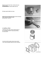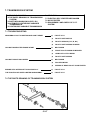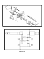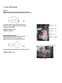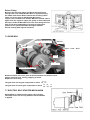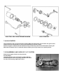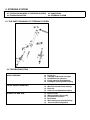
1
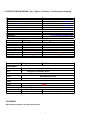
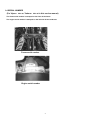
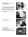
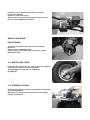
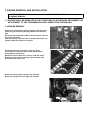
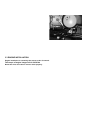
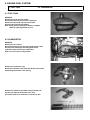
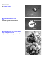
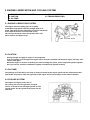
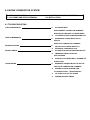
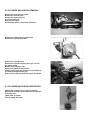
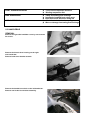
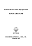
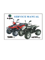
SERVICE MANUAL
CONTENTS
1. INFORMATION
2. MAINTENANCE
3. ENGINE REMOVAL AND INSTALLATION
4. ENGINE FUEL SYSTEM
5. ENGINE LUBRICATION AND COOLING SYSTEM
6. ENGINE COMBUSTION SYSTEM
7. TRANSMISSION SYSTEM
8. STEERING SYSTEM
9. FRONT WHEEL SYSTEM
10.
REAR WHEEL SYSTEM
11.
FENDERS AND EXHAUST PIPE
12.
ELECTRICAL SYSTEM
13.
TROUBLE SHOOTING
1. INFORMATION
1.1
1.2
1.3
SAFTY
NOTES
SPECIFICATION
1.4
1.5
SERIAL NUMBER
TORQUE VALUE
1.1 SAFETY
GASOLINE
Gasoline is extremely flammable and is explosive under certain condition.
Do not smoke or allow sparks or flames in your work area.
ϥ
CARBON MONOXIDE
Never run the engine in a closed area. The exhaust contains poisonous carbon
monoxide gas that may cause loss of consciousness and lead to death.
ϥ
BATTERY ELECTROLYTE
The battery electrolyte contains sulfuric acid. Protect your eyes, skin and
clothing. If you contact it, flush thoroughly with water and call a doctor if electrolyte
gets in your eyes.
ϥ HOT PARTS
Engine and exhaust pipe become very hot and remain hot for one hour after the
engine is run. Wear insulated gloves before handling these parts.
ϥ USED ENGINE/GEAR OIL
Used engine oil and gear oil may cause skin disease if repeatedly contact with
the skin for long periods.
Keep out of reach of children.
1.2 NOTES
All information, illustrations, directions and specifications included in this publication are base on the latest
product information available at the time of approval for printing.
JI-EE Dynamic Technology Industry Co., Ltd. reserves the right to make changes at any time without notice
and without incurring any obligation whatever.
No part of this publication may be reproduced without written permission.
2
1.3 SPECIFICATION ENGINE (for ViperST & YukonST in this service manual)
Type
Displacement
Bore and Stroke
Compression ratio
Maximum Torque (Nm/rpm)
Maximum Power (ps/rpm)
Two cycle air cooled
49.3 c.c.
40.0X39.2mm
6.8:1
4.5 Nm/6000rpm
3.8 ps/6000rpm
Carburetor
Ignition
Starting
Lubrication
Transmission
Piston type
Capacitor Discharge
Electric and kick starter
Forced pressure and wet sump
Automatic (C.V.T. V-belt) Fr Neut .Rev
CHASSIS
Overall Length
Overall Width
Overall Height
Seat Height
Wheel base
Ground Clearance
Dry Weight
Fuel Tank Capacity
ViperST
YukonST
EXL-50
1670 mm
940 mm
1040 mm
760 mm
1110 mm
120 mm
152 kg
4.5 Liters
ViperST
EXL-50
1750 mm
1010 mm
1065 mm
760 mm
1115 mm
120 mm
152 kg
4.5 Liters
YukonST
EXL-50
EXL-50
SUSPENSION
Front
Rear
Single A-arm / Adjustable Shocks
Swing Arm / Adjustable Shock
BRAKES
Front
Dual Mechanical drum
Rear
Hydraulic Disc
TIRES
Front
Rear
PRESSURE
Front
Rear
20/6-10
20/10-9
˰psi (0.23 kgf/cm2)˱ġ
12(0.8)
12(0.8)
12(0.8)
12(0.8)
COLORING
Specifications subject to change without notice.
3
1.4 SERIAL NUMBER
(For ViperST EXL-50 / YukonST EXL-50 in this service manual)
The frame serial number is stamped on the front of the frame.
The engine serial number is stamped on the left side of the crankcase.
Frame serial number
Engine serial number
4
.5 TORQUE VALUES
(For EXL 50 in this service manual)
STANDARD
ϥ
5 mm bolt and nut
5 N.m (3.5 lbf.ft)
ϥ
6 mm bolt and nut
10 N.m (7.2 lbf.ft)
ϥ
8 mm bolt and nut
22 N.m (16 lbf.ft)
ϥ10 mm bolt and nut
35 N.m (25 lbf.ft)
ϥ12 mm bolt and nut
55 N.m (40 lbf.ft)
ENGINE
ϥ
Cylinder head nut
ϥ
Spark plug
ϥ
Cylinder head bolt
ϥ
Alternator bolt
28 N.m (20.7 lbf.ft)
12 N.m (8.9 lbf.ft)
20 N.m (14.8 lbf.ft)
8 N.m (5.9 lbf.ft)
FRAME
ϥ
Handlebar upper holder bolt
ϥ
Throttle housing cover screw
ϥ
Steering shaft nut
ϥ
Steering shaft holder bolt
ϥ
Wheel rim bolt
18 N.m (13.3 lbf.ft)
ϥ
Tie rod lock nut
35 N.m (25.8 lbf.ft)
ϥ
King pin nut
ϥ
Handlebar lower holder nut
40 N.m (29.5 lbf.ft)
ϥ
Front wheel bolt
24 N.m (17.7 lbf.ft)
ϥ
Front axle castle nut
40-60 N.m (30-45 lbf.ft)
ϥ
Front brake arm nut
4 N.m (3.0 lbf.ft)
ϥ
Rear brake arm nut
7 N.m (5.2 lbf.ft)
ϥ
Rear axle castle nut
40-60 N.m (30-45 lbf.ft)
ϥ
Rear wheel bolt
24 N.m (17.7 lbf.ft)
ϥ
Exhaust muffler mounting bolt
30 N.m (22.1 lbf.ft)
ϥ
Engine hanger bolt
30 N.m ( 22 lbf.ft)
ϥ
Rear axle holder bolt
90 N.m (65 lbf.ft)
ϥ
Swing arm pivot nut
90 N.m (65 lbf.ft)
ϥ
Rear shock absorber mounting nut
45 N.m (33 lbf.ft)
24 N.m (17.7 lbf.ft)
4 N.m (2.9 lbf.ft)
50 N.m (36.9 lbf.ft)
33 N.m (24 lbf.ft)
40 N.m (29 lbf.ft)
5
2. MAINTENANCE
2.1 MAINTENANCE DATA
2.2 MAINTENANCE SCHEDULE
2.3 FUEL TUBE
2.4 THROTTLE OPERATION
2.5 THROTTLE CABLE ADJUSTMENT
2.6 AIR CLEANER
2.7 SPARK PLUG
2.8 IDLE SPEED
2.9 DRIVE CHAIN
2.10 BRAKE SYSTEM
2.11 WHEELS AND TIRES
2.12 STEERING SYSTEM
2.13 TOE-IN
2.14 GEAR OIL
2.1 MAINTENANCE DATA
SPECIFICATION
SPARK PLUG:
SPARK PLUG GAP:
RECOMMENDED SPARK PLUGS:
THROTTLE LEVER FREE PLAY:
IDLE SPEED:
BRAKE LEVER FREE PLAY:
DRIVE CHAIN SLACK
FRONT/REAR TIRE PRESSURE
TOE-IN
0.6-0.7 mm
NGK BPR7HS
5-10 mm
1800±100 rpm
15-25 mm
10-25 mm
MIN 2 psi (12.5kpa)
5±10 mm
TORQUE VALUES
25-30 N.m
35-43 N.m
SPARK PLUG
TIE-ROD LOCK NUT
ENGINE OIL
JASO FC Grade or same degree oil
GEAR LUBRICATION OIL
SAE 90
2.2 MAINTENANCE SCHEDULE
The maintenance internals in the follow table is based upon average riding, conditions. Riding in unusually
dusty areas, require more frequent servicing. (For ATV all serial in this service manual)
INITIAL SERVICE
(First week)
REGULAR SERVICE
(Every 30 operating days)
FUEL LINE
THROTTLE OPERATION
I
I
AIR CLEANER
C
SPARK PLUG
I
CARBURETOR IDLE SPEED
I
I
I, L
DRIVE CHAIN
I, L
BRAKE SHOE WEAR
BRAKE SYSTEM
I
I
NUT, BOLT, FASTENER
I
I
WHEEL
I
I
STEERING SYSTEM
SUSPENSION SYSTEM
C.V.T. AIR FILTER
C
GEAR OIL
REVERSE GEAR OIL-RXL90R
Note – I: Inspect and Clean, Adjust, Lubricate or Replace, if necessary
C: Clean
L: Lubricate
R: Replace
EVERY YEAR
I
I
I
I
R
R
2.3 FUEL TUBE
Inspect the fuel lines for deterioration, damage or
leakage and replace if necessary.
2.4 THROTTLE OPERATION
Inspect for smooth throttle lever full opening and
automatic full closing in all steering positions.
Inspect if there is no deterioration, damage or kinking
in the throttle cable, replace it if necessary.
Check the throttle lever, free play is 5-10 mm at the tip
of the throttle lever.
Disconnect the throttle cable at the upper end.
Lubricate the cable with commercially lubricant to
prevent premature wear.
2.5 THROTTLE CABLE ADJUSTMENT
Slide the rubber cap of the adjuster off the throttle
Housing, loosen the lock nut and adjust the free play
of the throttle lever by turning the adjuster on the throttle
housing. Inspect the free play of the throttle lever.
2.6 AIR CLEANER
Unscrew the air cleaner cover screws.
Pull out the air filter element from the air cleaner case.
Wash the element in non-flammable solvent, squeeze
out the solvent thoroughly.
Let it dry.
Soak the filter element in gear oil and then squeeze
out the excess oil.
Install the element into air cleaner carefully.
2.7 SPARK PLUG
This spark plug located at the front of the engine.
Disconnect the spark plug cap and unscrew the spark plug.
Check the spark plug electrodes for wearness.
Change a new spark plug if the electrodes and insulator tip
appear unusually fouled or burned.
Discard the spark plug if there is apparent wear or if the
insulator is cracked or chipped.
The spark plug gap shall keep in 0.6-0.7mm.
With the sealing washer attached, thread the spark plug in
by hand to prevent cross threading.
Tighten the spark plug with 25-30 N.m
2.8 IDLE SPEED
Connect an engine speed meter.
Warm up the engine, 10 minutes are enough.
Turn the idle-speed adjust screw on the carburetor
to obtain the idle speed. “Turn in” (clockwise) will get higher
speed. “Turn out” (counter clockwise) will get lower speed.
IDLE SPEED: 1800±100 rpm
2.9 DRIVE CHAIN
Inspect the chain slack. The standard is 10-25mm.
Adjust the chain slack.
Loose the lock bolts (4 pcs) then adjust the drive chain
slack by turn the adjusting nut.
Tighten the four lock bolts.
When the drive chain becomes very dirty, it should be
removed, cleaned and lubricated by specify lubricator.
Using commercial chain lubricant to lubricate the drive
chain.
Clean the drive chain with kerosene and wipe it dry.
Inspect the drive chain for possible wear or damage.
Replace the chain, if it is worn excessively or damaged.
Inspect the sprocket teeth, if it is excessive wear
or damage, replace it.
Inspect the chain-tensioned roller.
Replace it, if necessary.
2.10 BRAKE SYSTEM
Inspect the front brake lever and cable for excessive
play or other damage.
Replace or repair if necessary.
Measure the free play of the brake lever at the end of the
brake lever. The standard of free play is 15-25 mm.
Inspect the rear brake lever and cable for excessive
play or other damage.
Replace or repair if necessary.
Measure the free play of the rear brake lever at the end of
the lever. The standard is 15-25 mm.
BRAKE SHOE WEAR
FRONT BRAKE
Release the front wheel and inspect the brake lining
thickness.
Service Limit: 2.0mm(0.08 inch)
If either lining is worn beyond the service limit, replace
Both brakes shoes.
2.11 WHEELS AND TIRES
Inspect the tire surfaces for cuts, nails or other sharp objects.
Check the tire surfaces at cold tire condition.
The standard of tire pressure is 1.2±0.3 psi.
(0.8 kgf/cm2)
2.12 STEERING SYSTEM
Check the free play of the steering shaft with the front wheels,
turned straight ahead.
When there is excessive play, inspect the tie-rod, kingpin
bushing and ball joint.
STEERING SHAFT HOLDER BUSHING
Remove the front fender first.
Remove the steering shaft holder and check the steering
shaft bushing for wears or damage.
If the bushing is worn or damaged, change a new
one.
Grease the steering shaft bushing and install the parts in the
reverse order of removal.
Torque: steering shaft holder bolt: 33 N.m (24 lbf.ft)
2.13 TOE-IN
Let the vehicle on level ground and the front wheels facing
straight ahead.
Mark the centers of the tires to indicate the axle center
height.
Measure the distance between the marks.
Carefully move the vehicle back, let the wheels have
turned 180 °, so the marks on the tires are aligned
with the axle center height.
Measure the distance between the marks.
Calculate the difference in the front and rear
measurements.
Toe-in: 5±10mm
If the toe-in is out of standard, adjust it by changing
the length of the tie-rods equally by turning the tie-rod
while holding the ball joint.
Tighten the lock nuts.
Torque: 35-43 N.m
2.14 GEAR OIL
Gear oil needs to be changed every year.
There is a gear oil release bolt at the rear of engine.
Unscrew this release bolt and can let the dirty oil flow out.
The re-add oil hole is on the engine case beside gearbox.
3. ENGINE REMOVAL AND INSTALLATION
3.1 SERVICE INFORMATION
3.2 ENGINE REMOVAL
3.3 ENGINE INSTALLATION
3.1 ENGINE SHALL BE REMOVED IN THE CONDITIONS OF NECESSARY REPAIRMENT OR
ADJUSTMENT TO THE TRANSMISSION AND COMBUSTION SYSTEM ONLY
3.2 ENGINE REMOVAL
Remove the seat and rear fender. (Chapter 11) Remove the
spark plug cap from the spark plug. Remove the exhaust
pipe.
Disconnect the carburetor cable by unscrew two screws on
top of the carburetor.
Take off oil pump cable from the oil pump control plate. Oil
pump is under the right side of engine.
Disconnect the wire connectors. There are three
connectors for carburetor auto-choke, starter motor
and generator respectively.
Remove the drive chain cover. This is under the chain.
Remove the drive chain retaining clip and master link,
and remove the drive chain.
Remove the three engine hanger nuts and bolts.
Remove the engine from the right side of frame.
3.3 ENGINE INSTALLATION
Engine installation is essentially the reverse order of removal.
The torque of engine hanger bolt is 24-30 Nm
Route the wires and cable in reverse order properly.
Ϫ
POORLY
Ϫ
UNPROPER ADJUSTMENT TO THE
IDLE SPEED SCREW
IGNITION MALFUNCTION
Ϫ
FUEL/AIR MIXTURE RATIO NO GOOD
Ϫ
AIR CLEANER DIRTY
Ϫ
INSULATOR LEAKS
Ϫ
FUEL TANK CAP BREATHING HOLE
CLOGGED
LEAN MIXTURE
Ϫ
Ϫ
FUEL TANK CAP BREATHING HOLE
CLOGGED
Ϫ
FUEL FILTER CLOGGED
Ϫ
FUEL FLOWS IN THE TUBE
Ϫ
RICH MIXTURE
FUEL JET OF CARBURETOR CLOGGED
UNSMOOTHLY
FLOAT LEVEL IN CARBURETOR TOO
LOW
Ϫ
FLOAT NEEDLE VALVE IN
CARBURETOR FAULTY
Ϫ FLOAT LEVEL TOO HIGH
Ϫ
Ϫ
AIR DUCT IN CARBURETOR IS
CLOGGED
AIR CLEANER DIRTY
4. ENGINE FUEL SYSTEM
4.1 FUEL TANK
4.2 CARBURETOR
4.1 FUEL TANK
REMOVAL
Remove the seat and rear fender.
Disconnect the fuel line from the carburetor.
Remove the fuel tank cap and front fender.
Unscrew the fuel tank fixed bolts.
Note: Keep gasoline away from flames or sparks.
Wipe up spilled gasoline at once.
4.2 CARBURETOR
REMOVAL
Remove the air cleaner.
Disconnect the fuel line and auto-choke electric wire.
Unscrew the intake pipe mounting bolts at the
carburetor then removes the carburetor.
Note: Turn fuel cup on (off) position
Remove the carburetor cap.
Remove the throttle cable from the throttle valve while
depressing the throttle valve spring.
Remove the needle clip retainer, the jet needle and
needle clip. Inspect the throttle valve and
jet needle surface for wearness, scratches or dirt.
DISASSEMBLY
Unscrew the float chamber screws and remove
the carburetor chamber.
carburetor chamber
Disassembly the float and float needle
valve.
Inspect the seat of the float needle valve for
wear or damage.
Disassembly the slow jet, main jet, throttle adjusting
screw and air flow adjusts screw.
Inspect all the jets and screws for wear or damage. Clean
the passages and jets with compressed air.
throttle adjusting screw
air flow adjusts screw
main jet
slow jet
ASSEMBLY
Clean all parts in solvent and blow it dry with compressed air.
Assembly is essentially the reverse order of disassembly.
THROTTLE VALVE ASSEMBLY
Install the needle clip on the jet needle.
Install the jet needle into the throttle valve.
Assembly the throttle cable, spring and the throttle valve.
Align the throttle valve groove with the idle speed adjust
screw and install the carburetor cap to the carburetor.
5. ENGINE LUBRICATION AND COOLING SYSTEM
5.1 ENGINE LUBRICATION SYSTEM
5.2 CAUTION
5.3 OIL PUMP
5.4 COOLING SYSTEM
5.5 TROUBLESHOOTING
5.1 ENGINE LUBRICATION SYSTEM
The engine drives the pump gears of oil pump
crankshaft. Pump gears rotate the plunger shaft in oil
pump. This shaft sent the lubricating oil into the crankcase
to mix with the mixture of air-fuel flow evenly.
The oil drops and foam cover the cylinder inner wall,
piston surface and piston rings.
5.2 CAUTION
Having enough oil supply to engine is very important.
If the oil quantity is not enough, this engine will be serious scratched, and then this engine will stop, even
cannot work again.
When this engine is serious scratched, you need to change the piston, piston rings and cylinder together.
Also you need to check the combustion system and lubrication system carefully.
5.3 OIL PUMP
The quantity of oil that deliver out from oil pump increased by the engine speed and the carburetor throttle
open width. Oil pump is under the right side of the engine and connected by a control cable of throttle.
5.4 COOLING SYSTEM
The engine-cooling fan sucks the air.
The cooling fan is on the right side of engine.
The air is forced to flow through cylinder fin and
cylinder head. So, the cylinder and piston will not
over heat.
5.5 TROUBLESHOOTING
NO ENOUGH OIL SUPPLY TO ENGINE
Ϫ
Ϫ
Ϫ
Ϫ
Ϫ
Ϫ
THE OIL LEVEL IN OIL TANK IS TOO LOW.
OIL TUBES WERE NOT FIXED WELL.
OIL HAS LEAKAGED FROM TUBE ENDS.
OIL TUBES WERE BROKEN.
OIL TUBES WERE CLOGGED.
OIL PUMP CANNOT WORK.
ALWAYS INSUFFICIENT OIL LEVEL
IN LUBRICATE OIL TANK
Ϫ
Ϫ
Ϫ
EXTERNAL OIL LEAKS
WORN CYLINDE HEAD GASKET
WORN PISTON RINGS
6. ENGINE COMBUSTION SYSTEM
11.1 TROUBLESHOOTING
11.3 CYLINDER AND PISTON INSPECTION
11.2 CYLINDER AND PISTON REMOVAL
11.4 INSTALLATION
6.1 TROUBLESHOOTING
LOW COMPRESSION
ଘ
CYLINDER HEAD
HEAD GASKET LEAKING OR DAMAGED
WARPED OR CRACKED CYLINDER HEAD
HIGH COMPRESSION
ଘ
CYLINDER OR PISTON RINGS WORN OUT
ଘ
EXCESSSIVE CARBON BUILD-UP ON
PISTON
HEAD OR IN COMBUSTION CHAMBER
EXCESSIVE NOISE
EXCESS SMOKE
ଘ
PISTON AND CYLINDER WORN OUT
ଘ
EXCESSIVE CARBON BUILD-UP
ଘ
CYLINDER OR PISTON RINGS WORN OUT
ଘ
IMPROPER INSTALLATION OF
PISTON RINGS
ଘ
PISTON OR CYLINDER WALL SCORED OR
SCRATCHED
OVERHEATING
ଘ
EXCESSIVE CARBON BUILD-UP ON THE
PISTON OR COMBUSTION CHAMBER
ଘ
ଘ
ଘ
ENGINE COOLING SYSTEM (FAN,
CYLINDER COVER…) WORKS BADLY.
OIL SUPPLY IS OUT OF ORDER.
WRONG IGNITION TIMING
6.2 CYLINDER AND PISTON REMOVAL
Remove the seat and rear fender.
Remove the exhaust pipe.
Remove the spark plug cap.
Disconnect the wire.
Drag out the engine.
Disassembly the air cleaner and carburetor.
Remove the intake pipe mounting bolts.
Remove the cylinder bolt nuts.
Remove the cylinder head.
Remove the cylinder carefully, then you can see
the whole piston.
Remove one piston pin clip.
Remove the piston and piston pin.
Spread each piston ring and remove it by lifting up
at a point just opposite the gap.
Note: Don’t let the clip drop into engine crankcase.
6.3 CYLINDER AND PISTON INSPECTION
Inspect the cylinder bore for wear or damage.
Measure the cylinder inner diameter at three levels
in X and Y-axis.
Taper limit: 0.10 mm
Out of round: 0.10 mm
Check the cylinder head mating surface for warp
with a straight edge and feeler gauge.
Service limit: 0.10 mm
Insert each piston ring into the cylinder, and measure
the end gap.
Service limit: 0.5 mm
Measure the clearance between ring and groove.
Service limit: 0.09 mm
Measure the piston outer diameter at 10 mm high
from the skirt’s bottom.
Service limit: 39.9 mm
Measure the piston pin bore, and the piston pin
outer diameter.
Pin outer diameter service limit: 9.96 mm
Pin bore service limit: 10.04 mm
Measure the connecting rod small end inner diameter
with a small bore diameter gauge.
Service limit: 14.06 mm
6.4 INSTALLATION
Install the piston rings with the marks facing up.
Do not damage the piston rings by spreading
the ends too far.
Clean the cylinder gasket surface being careful
not to drop any gasket material into the crankcase.
Apply some oil to inside of the connecting rod small end.
Install the piston, piston pin and clip.
Install the piston with the arrow mark facing
the exhaust pipe.
Do not align the piston pin clip end gap with
the piston cutout.
Install a new cylinder gasket.
Apply a thin coat of engine oil to the piston rings
and cylinder wall.
Install the cylinder, compressing the piston rings.
Replace a new cylinder head gasket.
Install the cylinder head.
Tighten the cylinder-mounting bolt.
The torque is 10-14N.m
7. TRANSMISSION SYSTEM
7.1 TROUBLE SHOOTING
7.2 THE PARTS DRAWING OF TRANSMISSION
SYSTEM
7.3 SHIFT MECHANISM (INCLUDE C.D.I)
7.4 AUTOMATIC CONTINUOUS VARIABLE
TRANSMISSION
7.5 CONTINUOUS VARIABLE TRANSMISSION
7.6 GEAR BOX
7.7 ELECTRIC SELF-STARTER MECHANISM
7.8 KICK STARTER
7.9 DISASSEMBLY AND CHECK OF C.V.T.
SYSTEM
7.1 TROUBLESHOOTING
Ϫ
FAULTY C.D.I
Ϫ
FAULTY SHIFT MOTOR
Ϫ
FAULTY SENSOR (F, N1, R, N2)
Ϫ
FAULTY SHIFT SPRING OR GEAR
Ϫ
BELT WORN
Ϫ
FRONT PULLEY WORN OR BROKEN
Ϫ
LINING OF CLUTCH WORN
Ϫ
FAULTY SHIFT SPRING
Ϫ
BELT WORN
Ϫ
ROLLERS WORN
Ϫ
SPRING OF REAR PULLEY IS DISTORTED
ENGINE STOP AFTER SHIFT SUCCESSFULLY
Ϫ
FAULTY C.D.I
THE FUNCTION OF SPEED LIMITED IS ABNORMAL
Ϫ
FAULTY C.D.I
ABNORMALLY ACT IN SHIFTING AND CAN’T RESET
CAN NOT MOVE AFTER ENGINE START
CAN NOT RUN AT HIGH SPEED
7.2 THE PARTS DRAWING OF TRANSMISSION SYSTEM
C.V.T
Shift Mechanism
Gear Box For
7.3 SHIFT MECHANISM
Sensor
Inspect wire for break or damage and check contact.
Measure sensor dimension as fig-1 after unscrew sensor.
fig-1
If length is below 30mm, it must be replaced.
Smear with loctite 5699 and screw with torque
25 kgf-cm in assembly.
SERVICE LIMITS: 30 mm
TORQUE: 25 kgf-cm
Sensor
N2
Sensor
R
Sensor
N1
Sensor
F
Shift Spring and Gear
Remove mission side cover and other parts.
Check shift gear for wear or damage.
Measure open width of shift spring as fig-2.
Shift
Motor
Shift Spring
fig-2
If open width greater than 5mm, it must be replaced.
SERVICE LIMITS: 5 mm
Shift
Gear
Shift Motor
Check shift motor whether it’s action is normal as follow
data:
Disassembly mission side cover, parts of shift mechanism
and mission cover.
Get seal and bearing after disassembly shift motor of
mission cover.
Check seal and for wear or fatigue.
Replace it if necessary.
Brush
Seal
7.4 AUTOMATIC CONTINUOUS VARIABLE TRANSMISSION
This transmission is the combination of automatic
centrifugal clutch and V-belt continuous variable
transmission, which can change the transmission
ratio automatically.
When engine speed increase, the drive pulley will
be push to belt by the centrifugal force from six rollers.
Then the pitch circle of belt in drive pulley will
be larger.
The belt at driven pulley is forced to move to
the center of shaft, then the radius of pitch circle
is decreased.
The transmission ratio is therefore altered by the
alteration of pitch circle’s radius.
(In the drawing, “H” means high speed, “L” means low speed)
7.5 CONTINUOUS VARIABLE TRANSMISSION
V-Belt
Made of rubber fiber, resistant to head, pressure and
abrasion. The inner side of the Belt is toothed.
Drive Pulley
Due to the increasing engine speed, the rollers push
the movable drive face by centrifugal force. Then the
belt is pressed and enlarges its turning radius.
The aluminum fan is installed on the exterior of fixed
drive face. It can reduce the belt temperature.
Bearing
Driven Pulley
Because the revolving radius of V-Belt at the Drive End is
enlarged, the Face Comp Movable Drive is squeezed out by
the V-Belt at the Driven End to shorten the revolving radius.
There is a Torque Cam on the Movable Drive Face.
Torque Cam is loaded from outside. When the outside load is
higher than the engine’s output, the pulley of fixed shaft and
belt slip to make the Movable Drive Face move along the inner
side of Cam and compensate to increase to high torque
(toward to low speed) and make the engine maintain
smooth running with original revolution.
7.6 GEAR BOX
Reverse Shaft Comp
Sensor
Drive Shaft
Comp
Drum Gear Shift
Fork
Fork
Shaft
Counter Shaft Comp
Remove mission side cover, parts of shift mechanism and mission cover.
Inspect gears for wear, scoring, chipping or break.
Replace it if necessary.
The gear ratio of front gear composition is about
47 x 31
15 11
The gear ratio of reverse gear composition is about
49 49
31
×
×
15 16
11
7.7 ELECTRIC SELF-STARTER MECHANISM
Starter Motor is installed on the upper side of engine.
The starter motor can act only when the left hand brake
is applied.
ELECTRIC SELF-STARTER MECHANISM
KICK STARTER
7.8 KICK STARTER
This kick-starter arm is on the left side of engine. When the kick-starter arm is kicked, the gear of start
shaft will drive the kick-starter to revolve the crankshaft to start the engine.
After the engine is started, the kick-started will stop transfer the power to the kick-starter driven gear.
When the kick-starter lever is released, the kick-starter gear will go back to its original position.
7.9 DISASSEMBLY AND CHECK OF C.V.T. SYSTEM
Remove the engine clutch cover, by unscrew
the fixed bolts.
Check the belt for wear. If necessary, replace the belt.
Disassembly the front drive pulley, check the six rollers
for wear. If necessary, replace the rollers.
8. STEERING SYSTEM
8.1 THE PARTS DRAWING OF STEERING SYSTEM
8.2 TROUBLESHOOTING
8.3 HANDLEBAR
8.4 STEERING SYSTEM
8.1 THE PARTS DRAWING OF STEERING SYSTEM
8.2 TROUBLESHOOTING
HARD STEERING
FRONT WHEEL WOBBLING
STEERS TO ONE SIDE
Ϫ
Ϫ
Ϫ
Ϫ
Ϫ
Faulty tire
Steering shaft holder too tight
Insufficient tire pressure
Faulty steering shaft bushing
Damaged steering shaft bushing
Ϫ
Ϫ
Ϫ
Ϫ
Faulty tire
Worn front brake drum bearing
Bent rim
Axle nut not tightened properly
Ϫ
Ϫ
Ϫ
Ϫ
Ϫ
Ϫ
Bent tie rods
Wheel installed incorrectly
Unequal tire pressure
Bent frame
Worn swing arm pivot bushings
Incorrect wheel alignment
FRONT SUSPENSION NOISE
˜ġ Loose front suspension fasteners
˜ġ Binding suspension link
HARD SUSPENSION
˜ġ
˜ġ
˜ġ
˜ġ
˜ġ
SOFT SUSPENSION
8.3 HANDLEBAR
REMOVAL
Remove the right side handlebar cover by unscrew two
fix screws.
Remove the throttle lever housing on the right
side handle bar.
Remove brake lever bracket assemb
Remove the handle bar switch on the left handle bar.
Remove rear brake lever bracket assembly.
Faulty front swing arm bushings
Improperly installed front swing arms
Bent front shock absorber swing rod
Weak front shock absorber springs
Worn or damage front swing arm bushings