1
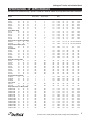
Shelleyspeed™
Service and Installation Manual
Please read this manual completely before attempting to install or operate this equipment!
Notify carrier of damage! Inspect all components immediately.
Refrigerated, Heated and Non-Electrical Units
CAUTION
Important Information
Read Before Use
Please Save These Instructions!
February 2013
Shelleyspeed™ Service and Installation Manual
Important Warning And Safety Information
WARNING
Read This Manual Thoroughly Before Operating, Installing, Or Performing Maintenance On The Equipment.
WARNING
Failure To Follow Instructions In This Manual Can Cause Property Damage, Injury Or Death.
WARNING
Do Not Store Or Use Gasoline Or Other Flammable Vapors Or Liquids In The Vicinity Of This Or Any Other
Appliance.
WARNING
Unless All Cover And Access Panels Are In Place And Properly Secured, Do Not Operate This Equipment.
WARNING
This Appliance Is Not Intended For Use By Persons Who Lack Experience Or Knowledge, Unless They Have
Been Given Supervision Or Instruction Concerning Use Of The Appliance By A Person Responsible For Their
Safety.
WARNING
This Appliance Is Not To Be Played With.
Warning
Do Not Clean With Water Jet.
WARNING
Do Not Use Electrical Appliances Inside The Food Storage Compartment Of This Appliance.
CAUTION
Observe the following:
•
Minimum clearances must be maintained from all walls and combustible materials.
•
Keep the equipment area free and clear of combustible material.
•
Allow adequate clearance for air openings.
•
Operate equipment only on the type of electricity indicated on the specification plate.
•
Unplug the unit before making any repairs.
•
Retain this manual for future reference.
2
For customer service, call (800) 733-8829, (800) 773-8821, Fax (989) 773-3210, www.delfield.com
Shelleyspeed™ Service and Installation Manual
CONTENTS
Receiving & Inspecting Equipment............................................ 3
Serial Number Information......................................................... 4
Warranty Information.................................................................. 4
Regulatory Certifications............................................................. 4
Specifications...........................................................................5-6
Heated Unit Info ......................................................................7-8
Heated Merchandiser Info........................................................... 9
Refrigerator/Freezer Unit Info..............................................10-12
Wiring Diagrams..................................................................13-15
Replacement Parts List.............................................................16
Standard Labor Guidelines.......................................................17
Notes....................................................................................18-19
Receiving and Inspecting the Equipment
Even though most equipment is shipped crated, care should
be taken during unloading so the equipment is not damaged
while being moved into the building.
1. Visually inspect the exterior of the package and skid or
container. Any damage should be noted and reported to
the delivering carrier immediately.
2. If damaged, open and inspect the contents with the
carrier.
3. In the event that the exterior is not damaged, yet upon
opening, there is concealed damage to the equipment
notify the carrier. Notification should be made verbally
as well as in written form.
4. Request an inspection by the shipping company of the
damaged equipment. This should be done within 10
days from receipt of the equipment.
5. Check the lower portion of the unit to be sure legs or
casters are not bent.
6. Also open the compressor compartment housing and
visually inspect the refrigeration package. Be sure lines
are secure and base is still intact.
7. Freight carriers can supply the necessary damage forms
upon request.
8. Retain all crating material until an inspection has been
made or waived.
Uncrating the Equipment
First cut and remove the banding from around the crate.
Remove the front of the crate material. If the unit is on legs,
remove the top of the crate as well and lift the unit off the
skid. If the unit is on casters, it can be rolled off the skid.
3
For customer service, call (800) 733-8829, (800) 773-8821, Fax (989) 773-3210, www.delfield.com
Shelleyspeed™ Service and Installation Manual
Serial Number Information
Always have the serial number of your unit available when
calling for parts or service.
Serial number is located beside the power switch. (Power
switch is located on upper right hand corner of operator
side.)
This manual covers standard units only. If you have a
custom unit, consult the customer service department at the
number listed below.
©2013 The Delfield Company. All rights reserved. Reproduction without
written permission is prohibited.
“Delfield” is a registered trademark of The Delfield Company.
Warranty Information
Visit http://www.delfield.com/minisite/service/warranty_info to:
• Register your product for warranty.
• Verify warranty information.
• View and download a copy of your warranty.
Regulatory Certifications
All Models are certified by:
National Sanitation Foundation (NSF)
Electical models are also certified by:
Underwriters Laboratories (UL)
Underwriters Laboratories of Canada (ULC)
4
For customer service, call (800) 733-8829, (800) 773-8821, Fax (989) 773-3210, www.delfield.com
Shelleyspeed™ Service and Installation Manual
Specifications, 30” DEPTH MODULES
This manual covers standard units only. If you have a custom unit, consult the customer service department at the number listed below.
ModelLength Width HeightBasket CapacityVoltage Nema
Amp H.P.
Refrigerant BTU
Number 20.5x13.25x2.5” 20.5x13.25x4.75”
Plug
Refrigerated Module (134A)
SPR-40
40 30 34
12
6
1155-15P 5.01/5 16oz. 1470
SPR-40E
403030
8 4
115
5-15P
5.0
1/516oz.
1470
SPR-50
50 30 34
18
9
1155-15P 7.01/4 16oz. 2280
SPR-50E
50 30 30
12
6
1155-15P 7.01/4 16oz. 2280
SPR-64
64 30 34
24
12
1155-15P 7.01/4 16oz. 2280
SPR-64E
64 30 30
16
8
1155-15P 7.01/4 16oz. 2280
Freezer Module (404A)
SPF-42
42 30 34
10
5
1155-15P 8.01/3 24oz. 1440
SPF-42E
423030
8 4
115
5-15P
8.0
1/324oz.
1440
SPF-52
52 30 34
15
7
1155-15P 8.01/3 24oz. 1440
SPF-52E
52 30 30
12
6
1155-15P 8.01/3 24oz. 1440
SPF-66
66 30 34
20
10
1155-15P 8.01/3 24oz. 1440
SPF-66E
66 30 30
16
8
1155-15P 8.01/3 24oz. 1440
Refrigerator/Freezer Module(134A & 404A)
SPRF-68
68
30
34
12
6
120
5-20P 15.0 1/5, 1/3 16oz./24oz.1440/1470
SPRF-68E
68
30
30
16
8
120
5-20P
15.0 1/5, 1/3 16oz./24oz.1440/1470
Refrigerator/Heater Module (134A)
SPRH-68
68
30
34
12
6
120
5-30P
18.5 1/5 16oz. 1470 SPRH-68E
68
30
30
8
4
120
5-30P
18.5 1/5 16oz. 1470
Heated Module
SPH-40
40
30
34
12
6
120
5-30P
17.0
NA
NA
NA
SPH-40E
403030
8 4
120
5-30P
17.0
NA NA NA
SPH-50
50
30
34
18
9
120
5-30P
17.0
NA
NA
NA
SPH-50E
50
30
30
12
6
120
5-30P
17.0
NA
NA
NA
SPH-64
64
30
34
24
12
120
5-30P
17.0
NA
NA
NA
SPH-64E
64
30
30
16
8
120
5-30P
17.0
NA
NA
NA
Utility (Merchandising) Module
SPM-28
28 30 34
NA
NA
NA NA NANA
NA NA
SPM-28E
28 30 30
NA
NA
NA NA NANA
NA NA
SPM-36
36 30 34
NA
NA
NA NA NANA
NA NA
SPM-36E
36 30 30
NA
NA
NA NA NANA
NA NA
SPM-50
50 30 34
NA
NA
NA NA NANA
NA NA
SPM-50E
50 30 30
NA
NA
NA NA NANA
NA NA
SPM-60
60 30 34
NA
NA
NA NA NANA
NA NA
SPM-60E
60 30 30
NA
NA
NA NA NANA
NA NA
SPM-74
74 30 34
NA
NA
NA NA NANA
NA NA
SPM-74E
74 30 30
NA
NA
NA NA NANA
NA NA
Heated / Merchandising Module
SPHM-50
503034
6 3
120
5-20P
14.75
NA NA NA
SPHM-50E 503030
6 3
120
5-20P
14.75
NA NA NA
SPHM-64
643034
8 4
120
5-20P
16.3
NA NA NA
SPHM-64E 643030
8 4
120
5-20P
16.3
NA NA NA
Cashier Stand
SPCS-30
30 30 34
NA
NA
NA NA NANA
NA NA
SPCS-30E
30 30 30
NA
NA
NA NA NANA
NA NA
Refrigerated Display Case Module (134A)
SPRD36P-36N 36 30 76
NA
NA
115 5-15P 12.01/2 32oz. 4450
SPRD36P-50N 50 30 76
NA
NA
115 5-15P 12.01/2 32oz. 4450
SPRD48P-50N 50 30 76
NA
NA
115 5-15P 12.01/2 32oz. 4450
SPRD48P-60N 60 30 76
NA
NA
115 5-15P 12.01/2 32oz. 4450
SPRD60P-60N
60
30
76
NA
NA
115
5-20P
16.0
3/4
48oz.
7470
SPRD60P-74N
74
30
76
NA
NA
115
5-20P
16.0
3/4
48oz.
7470
SPRD72P-74N
74
30
76
NA
NA
115
5-20P
16.0
3/4
48oz.
7470
SPRD36P-36NE 36 30 76
NA
NA
115 5-15P 12.01/2 32oz. 4450
SPRD36P-50NE 50 30 76
NA
NA
115 5-15P 12.01/2 32oz. 4450
SPRD48P-50NE 50 30 76
NA
NA
115 5-15P 12.01/2 32oz. 4450
SPRD48P-60NE 60 30 76
NA
NA
115 5-15P 12.01/2 32oz. 4450
SPRD60P-60NE
60
30
76
NA
NA
115
5-20P
16.0
3/4
48oz.
7470
SPRD60P-74NE
74
30
76
NA
NA
115
5-20P
16.0
3/4
48oz.
7470
SPRD72P-74NE
74
30
76
NA
NA
115
5-20P
16.0
3/4
48oz.
7470
5
For customer service, call (800) 733-8829, (800) 773-8821, Fax (989) 773-3210, www.delfield.com
Shelleyspeed™ Service and Installation Manual
Specifications, 35” DEPTH MODULES
This manual covers standard units only. If you have a custom unit, consult the customer service department at the number listed below.
ModelLength Width HeightBasket CapacityVoltage Nema
Amp H.P. Refrigerant
BTU
Number
20.5x13.25x2.5 20.5x13.25x4.75
Plug
Refrigerated Module (134A)
SPR-40W
40
35
34
12
6
115
5-15P
5.0
1/5
16oz.
1470
SPR-40EW 403530
8 4
115
5-15P
5.0
1/516oz.
1470
SPR-50W
50 35 34
18
9
1155-15P 7.01/4 16oz. 2280
SPR-50EW
50 35 30
12
6
1155-15P 7.01/4 16oz. 2280
SPR-64W
64 35 34
24
12
1155-15P 7.01/4 16oz. 2280
SPR-64EW
64 35 30
16
8
1155-15P 7.01/4 16oz. 2280
Freezer Module (404A)
SPF-42W
42 35 34
12
6
1155-15P 8.01/3 24oz. 1440
SPF-42EW 423530
8 4
115
5-15P
8.0
1/324oz.
1440
SPF-52W
52 35 34
18
9
1155-15P 8.01/3 24oz. 1440
SPF-52EW
52 35 30
12
6
1155-15P 8.01/3 24oz. 1440
SPF-66W
66 35 34
24
12
1155-15P 8.01/3 24oz. 1440
SPF-66EW
66 35 30
16
8
1155-15P 8.01/3 24oz. 1440
Refrigerator/Freezer Module (134A & 404A)
SPRF-68W
68
35
34
24
12
120
5-20P
15.0 1/5, 1/3 16oz./24oz.1440/1470
SPRF-68EW
68
35
30
8
4
120
5-20P
15.0 1/5, 1/3 16oz./24oz.1440/1470
Refrigerator/Heater Module (134A)
SPRH-68W
68
35
34
12
6
120
5-30P
18.5 1/5 16oz. 1470 SPRH-68EW
68
35
30
8
4
120
5-30P
18.5 1/5 16oz. 1470
Heated Module
SPH-40W
40 35 34
12
6
120 5-30P 17.0NA
NA NA
SPH-40EW 403530
8 4
120
5-30P
17.0
NA NA NA
SPH-50W
50 35 34
18
9
120 5-30P 17.0NA
NA NA
SPH-50EW
50 35 30
12
6
120 5-30P 17.0NA
NA NA
SPH-64W
64 35 34
24
12
120 5-30P 17.0NA
NA NA
SPH-64EW
64 35 30
16
8
120 5-30P 17.0NA
NA NA
Utility (Merchandising) Module
SPM-28W
28 35 34
NA
NA
NA NA NANA
NA NA
SPM-28EW
28 35 30
NA
NA
NA NA NANA
NA NA
SPM-36W
36 35 34
NA
NA
NA NA NANA
NA NA
SPM-36EW
36 35 30
NA
NA
NA NA NANA
NA NA
SPM-50W
50 35 34
NA
NA
NA NA NANA
NA NA
SPM-50EW
50 35 30
NA
NA
NA NA NANA
NA NA
SPM-60W
60 35 34
NA
NA
NA NA NANA
NA NA
SPM-60EW
60 35 30
NA
NA
NA NA NANA
NA NA
SPM-74W
74 35 34
NA
NA
NA NA NANA
NA NA
SPM-74EW
74 35 30
NA
NA
NA NA NANA
NA NA
Heated/Merchandising Module
SPHM-50W 503534
6 3
120
5-20P
14.75
NA NA NA
SPHM-50EW 503530
6 3
120
5-20P
14.75
NA NA NA
SPHM-64W 643534
8 4
120
5-20P
16.3
NA NA NA
SPHM-64EW 643530
8 4
120
5-20P
16.3
NA NA NA
Cashier Stand
SPCS-30W
30 35 34
NA
NA
NA NA NANA
NA NA
SPCS-30EW 30 35 30
NA
NA
NA NA NANA
NA NA
Refrigerated Display Case Module (134A)
SPRD36P-36DW36 35 76
NA
NA
115 5-15P 12.01/2 32oz. 4450
SPRD36P-50DW50 35 76
NA
NA
115 5-15P 12.01/2 32oz. 4450
SPRD48P-50DW50 35 76
NA
NA
115 5-15P 12.01/2 32oz. 4450
SPRD48P-60DW60 35 76
NA
NA
115 5-15P 12.01/2 32oz. 4450
SPRD60P-60DW
60
35
76
NA
NA
115
5-20P
16.0
3/4
48oz.
7470
SPRD60P-74DW
74
35
76
NA
NA
115
5-20P
16.0
3/4
48oz.
7470
SPRD72P-74DW
74
35
76
NA
NA
115
5-20P
16.0
3/4
48oz.
7470
SPRD36P-36DEW36
35 76
NA
NA
115 5-15P 12.0 1/2
32oz. 4450
SPRD36P-50DEW50
35 76
NA
NA
115 5-15P 12.0 1/2
32oz. 4450
SPRD48P-50DEW50
35 76
NA
NA
115 5-15P 12.0 1/2
32oz. 4450
SPRD48P-60DEW60
35 76
NA
NA
115 5-15P 12.0 1/2
32oz. 4450
SPRD60P-60DEW 60
35
76
NA
NA
115
5-20P
16.0
3/4
48oz.
7470
SPRD60P-74DEW 74
35
76
NA
NA
115
5-20P
16.0
3/4
48oz.
7470
SPRD72P-74DEW 74
35
76
NA
NA
115
5-20P
16.0
3/4
48oz.
7470
6
For customer service, call (800) 733-8829, (800) 773-8821, Fax (989) 773-3210, www.delfield.com
Shelleyspeed™ Service and Installation Manual
Installation: Heated Units
Location
Do not install the unit near combustible objects or surfaces
affected by heat or moisture. Units are intended for indoor
use only.
Leveling
The unit must be level, both front and back and left to
right.
Stabilizing
Most models are supplied on casters for your convenience.
Electrical Connections
onnections must be made in accordance with
C
all applicable local codes and/or the National
Electrical Code. Refer to the amperage data on
the specification pages or the wiring diagrams. A
standard unit is provided with a power cord and
grounded plug. All units should be plugged into a
grounded receptacle with its own circuit protection
that matches the amperage of the plug.
T he unit must be installed in a stable condition
with the front wheels locked. Locking the front
casters after installation is the operator’s
responsibility.
Operation: Heated Units
After the unit is plugged into the proper power source, you
will need to turn on the main power switch. The main power
switch is located behind the hinged panel located at the
bottom center of the operators side of the equipment. If the
unit fails to operate at this point, check the night switch to
ensure it is in the ON position. (The night switch is located
on the top right of the operator’s side of the equipment
behind spring hinged cover.)
The purpose of the night switch is to allow the unit to remain
connected to the power source with the main power switch
in the ON position and turn the unit off at night or when not
in operation. The night switch will terminate power to the
unit with the exception of the fans. The fans will continue to
operate for a duration of 3 minutes to allow the elements to
cool and prevent overheating.
After usage DO NOT disconnect power from the
plug or from the main power switch as the fans
will not operate and a hi-limit may be tripped.
The unit is designed with a stay cool surface technology,
the top of the heated serving counter should remain at
approximately 80˚F. This will allow for the safe removal of
product from the baskets.
This unit is designed for DRY OPERATION ONLY!
Water is not required and should NEVER be used while the
unit is in operation or during the cleaning. Beneath the
false bottom on the interior of the equipment are the heating
elements, controls and wiring.
Operating with water or cleaning with water can
cause serious injury.
Proper air flow is critical to the operation of this equipment.
(Be sure to only use Delfield approved wire baskets for
storage of product). Other loading methods may cause air
flow restrictions and improper operation.
There is also a thermostat control located behind the
hinged panel at the bottom center of the operator’s side of
the equipment. This will allow the customer to adjust the
temperature for their desired requirements. The thermostat
has a three color range setting: YELLOW, GREEN and RED
with GREEN being the optimum range. This should allow the
unit to operate at temperatures that vary between 160˚ and
180˚ Fahrenheit. The desired product temperature at this
same setting is 140˚ to 160˚ Fahrenheit.
Due to the high temperatures, the inside of the
heated storage area is very hot and may cause
serious injury!
7
For customer service, call (800) 733-8829, (800) 773-8821, Fax (989) 773-3210, www.delfield.com
Shelleyspeed™ Service and Installation Manual
Operation: Heated Units continued
Product that is being stored in the Shellyspeed heated serving
counters are required to be properly heated prior to loading.
After rethermalizing product to desired temperature, it can
be placed in the wire baskets and loaded into the preheated
Shellyspeed heated unit. Preheating of equipment takes
approximately 1 hour. Hold time is 4 hours. The Shellyspeed
line is not designed for long-term storage of product. The
unit must be shut off properly with the night switch when not
in use.
Maintenance: Heated units
Maintenance
Wipe unit clean with a damp cloth. Never pour water or
cleaning solution directly into the Shellyspeed heated unit.
For tougher cleaning requirements a mild abrasive and damp
cloth may be used.
If it becomes necessary to inspect or replace components
on the Shellyspeed heated unit, the elements and hi-limit
can be accessed by removing the bottom panel from the
interior of the unit. Most other components can be accessed
through the hinged panel located at the bottom center of the
operator’s side.
Never use flammable oil soaked cloths or
combustible cleaning solutions, for cleaning.
Wipe casters down with food safe cleaner and fresh water.
8
For customer service, call (800) 733-8829, (800) 773-8821, Fax (989) 773-3210, www.delfield.com
Shelleyspeed™ Service and Installation Manual
Operation: Heated Merchandisers
After the unit is plugged into the proper power source, turn
on the main power switch. The main power switch is located
on the top right of the operator’s side of the equipment and is
located behind the spring hinge cover.
The merchandiser is heated by a 120-volt food warmer
mounted under the center shelf. The food warmer is
sufficient to heat both the lower and upper work surfaces.
The temperature control (infinite switch) for the food warmer
is located behind the right hand hinged door of the operator
side. The control can be set between 1 and 10 to maintain
proper temperatures.
There is a circulating fan for the lower work surface, which
allows for even temperatures across the lower area. The
circulating fan is located at the right end of the operator’s side
and can be accessed from the louver also located at the right.
The circulating fan assembly incorporates a 700 watt 120
volt heating element. The heating element is controlled by a
temperature control located at the bottom of the circulating
assembly. The control is set for “E”, this is the maximum
temperature control setting and has a variable setting of A
thru E. Any adjustments must be made by a qualified service
technician. The circulating fan will draw air in from the
intake at the right and discharge the heated air out the left air
diffuser.
There is a 120-volt incandescent light located in the top of the
overstructure. The incandescent light is controlled by the unit
power switch.
The merchandiser is designed to hold product above 140˚F.
Product must be properly heated prior to storage in the
merchandiser.
Maintenance: Heated Merchandisers
Maintenance
Wipe unit clean with a damp cloth. Never pour water or
cleaning solution directly into the Shelleyspeed heated unit.
For tougher cleaning requirements a mild abrasive and damp
cloth may be used.
Never use flammable oil soaked cloths or
combustible cleaning solutions for cleaning.
Merchandisers are standard with Plexiglas® ends and
also sliding Plexiglas® doors. The doors are removable by
lifting the door into the upper track and pulling the bottom
of the Plexiglas® out of the lower track, lower the Plexiglas®
and remove. Once removed, the lower sanilite track can
be removed and cleaned following the standard cleaning
procedures. There is also a cleanout located at the ends
of the track holder to remove any food product or debris.
Simply reverse the order to reinstall tracks and Plexiglas®.
With a wet a clean cloth with lukewarm water and
dishwashing liquid. Apply only light pressure, rinse with clear
water and blot dry with a damp chamois. For excessively
dirty surfaces, rinse surface dirt off before washing.
Note: Never use window sprays, kitchen scouring
compounds or solvents such as acetone, gasoline,
benzene, alcohol, carbon tetrachloride, or lacquer
thinner.
Fine scratches will disappear when you polish by hand with a
plastic cleaner polish.
Wipe casters down with food safe cleaner and fresh water.
Failure to follow these guidelines can result in cracked or
broken Plexiglas®.
9
For customer service, call (800) 733-8829, (800) 773-8821, Fax (989) 773-3210, www.delfield.com
Shelleyspeed™ Service and Installation Manual
Installation: Refrigerated/freezer Units
Electrical connection
Location
A standard refrigerated unit is provided with a power cord
and 3-prong grounded plug.
Be sure the location chosen has a floor strong enough
to support the total weight of the cabinet and contents,
approximately 1,000 pounds. Reinforce the floor as necessary
to provide for maximum loading. Units are intended for indoor
use only.
The unit should be plugged into a receptacle with its own
circuit protection that matches the amperage of the plug.
Connections
must be made in accordance with
all applicable local codes and/or the National
Electrical Code. Refer to the amperage data on
the specification pages or the wiring diagrams. A
standard unit is provided with a power cord and
grounded plug. All units should be plugged into a
grounded receptacle with its own circuit protection
that matches the amperage of the plug.
Leveling
The unit must be level, both front and back and left to
right.
Stabilizing
Most models are supplied on casters for your convenience.
n cord-connected units, an ON/OFF switch is
O
located on the operator side upper right hand
corner. The switch must be turned to its OFF
position and power supply disconnected whenever
doing the following:
T he unit must be installed in a stable condition
with the front wheels locked. Locking the front
casters after installation is the operator’s
responsibility.
1. Performing maintenance functions.
2. Cleaning the refrigerated cabinet area.
3. Performing service or repair functions.
Under no circumstances should the unit be
operated without the louvered panel in place.
OPERATION: Refrigerated Units
Inside cabinet: Do not pack unit so full that air cannot
circulate (only use Delfield approved wire baskets to store
product). See diagram to right.
Outside cabinet: Be sure the unit has access to ample air;
avoid hot corners and locations near stoves and ovens.
After the unit is plugged into the proper power source,
you will need to turn on the main power switch. The main
power switch is located on the top right of the operator’s
side of the equipment behind the spring hinged cover. If
the unit fails to operate, check the thermostat position
to make sure it is not in the OFF position. The optimum
setting for the temperature control is “5”. The temperature
control can be accessed through the removable louver
panel for the machine compartment located at the end of
the unit.
NOTE: Ice or water should never be used with this
equipment.
The Shelleyspeed refrigerator is also equipped with a defrost
timer. This allows for continuous operation throughout the
day. The timer is preset at the factory to defrost every four
hours for 15 minutes. The timer comes standard with a
lithium battery and will keep time for up to seven days in the
event of a power failure or if the unit is disconnected from the
power source. Even though the unit is set to defrost, it is still
recommended that all product be removed at night and the unit
shut off when not in use.
The unit will require approximately one hour of pre-chill
time prior to loading product. It is important the product
being stored in the refrigerated compartment is at or below
the desired holding temperature. The unit is designed to
store product, not to cool warm food product.
10
For customer service, call (800) 733-8829, (800) 773-8821, Fax (989) 773-3210, www.delfield.com
Shelleyspeed™ Service and Installation Manual
refrigerator TEMPERATURE Control Settings and defrost timer
Defrost timer: every 4 hours for 15 minutes.
11
For customer service, call (800) 733-8829, (800) 773-8821, Fax (989) 773-3210, www.delfield.com
Shelleyspeed™ Service and Installation Manual
Operation: freezer units
If it is necessary to adjust the temperature, the control is
located behind the louver on right end of unit. Turn the
knob clockwise as indicated on the control for desired
temperature. Adjustments should be made gradually.
Several small adjustments will be more effective than one
large adjustment. It may take an hour or longer to realize
the temperature change depending on the application and
location of the unit.
These units are not designed to freeze cold food products.
Items should be placed in the unit at the desired holding
temperature.
Maintenance: refrigerator and freezer units
Defrosting
Freezer units should be defrosted daily using the on/off
switch located on operator side upper right hand corner.
It is recommended that product be removed at night and the
unit shut off when not in use.
ever use sharp objects or tools to clean or
N
scrape ice/frost build up. A puncture to the
freezer could cause unrepairable damage to the
refrigeration system.
Overshelves and other items mounted to the top of the
counters should never be installed in the field due to the
potential damage to the refrigeration system.
Cleaning the unit
For stainless steel parts, use a mild, non-abrasive soap
or detergent and warm water. This may be followed by an
application of stainless steel cleaner or polish which will
eliminate water spotting and fingerprints.
Casters
Casters can be lubricated with penetrating type oil.
Recommended maintenance schedule
Daily: Wipe and/or wash food wells, unit surface and door
gaskets.
Monthly: Remove louvers and clean condensing coil with a
soft brush, a fin comb or vacuum cleaner brush attachment.
Remove dust and debris from fins without bending them.
Check casters for any debris that could be binding the
wheels, such as, strings from mops or bits of paper.
If it becomes necessary to inspect or repair components on
the Shelleyspeed refrigerated units, the fans and coils can be
accessed by removing the bottom panel from the interior of
the unit. Most other components can be located at the end
of the unit behind the removable louver panel.
12
For customer service, call (800) 733-8829, (800) 773-8821, Fax (989) 773-3210, www.delfield.com
Shelleyspeed™ Service and Installation Manual
Wiring Diagram — 115V REFRIGERATED units
L1
N
G
ON/OFF SWITCH
CONDENSING UNIT
TEMPERATURE CONTROL
DEFROST TIMER
EVAPORATOR FAN
Wiring Diagram — 115V freezer units
L1
N
G
ON/OFF SWITCH
CONDENSING UNIT
TEMPERATURE CONTROL
DEFROST TIMER
EVAPORATOR FAN
13
For customer service, call (800) 733-8829, (800) 773-8821, Fax (989) 773-3210, www.delfield.com
Shelleyspeed™ Service and Installation Manual
Wiring Diagram — 120V heated units
N
MAIN SWITCH
NIGHT SWITCH
L1
G
FAN
1
2
4
5
6
7
MIN.
MAX.
5
3
HEATER ELEMENTS
HI-LIMIT
SAFETY
TEMP.
CONTROL
WIRING DIAGRAM - 120V SHELLEYSPEED HEATED UNIT
Wiring Diagram — 120/208V heated units (OPTIONAL)
MAIN SWITCH
NIGHT SWITCH
L1
N
L2
G
FAN
1
2
3
5
6
7
MIN.
MAX.
3
5
TEMP.
CONTROL
HEATER ELEMENTS
HI-LIMIT
SAFETY
WIRING DIAGRAM - 115/208-230V MARK7 HEATED PLATE STORAGE
14
For customer service, call (800) 733-8829, (800) 773-8821, Fax (989) 773-3210, www.delfield.com
Shelleyspeed™ Service and Installation Manual
Wiring Diagram — 120V MERCHANDISER heated units
LIGHT
INFINITE CNTRL
HEATLAMP
N
MAIN SWITCH
T-STAT
(SET ON E=205˚)
L1
FAN
HEATER ELEMENT
G
HI-LIMIT
SAFETY
WIRING DIAGRAM - 120V SHELLEYSPEED HEATED MERCHANDISER UNIT
15
For customer service, call (800) 733-8829, (800) 773-8821, Fax (989) 773-3210, www.delfield.com
Shelleyspeed™ Service and Installation Manual
Parts List
HEATED MERCHANDISER UNIT
HEATED UNITS
120V UNIT
2162516
2183390
2190154
2194216
2194279
2194297
2194325
2194326
2194370
2194372
2194377
2194409
2194589
2194618
2194694
3234067
3234156
3234669
3234783
3234888
3516390
000-B9X-0031
000-B9X-0030
BLOWER, HI TEMP
CORD, 10/3, TYPE SO/STO/SJO, 105C
SWITCH, ROCKER, 20A
TERMINAL, RING, 12-10 GA., 1/4” STUD
GRIP, STRAIN RELIEF, 90, 10/3, CORD
PLUG, 30A-125V, NEMA 5-30P
BOX, ELECTRIC, 4.68 SQ. 56.7 KO
COVER, 4.6875 SQ., BLANK
SENSOR, TEMPERATURE, HEATED
THERMOSTAT, HEATED CABINET
KNOB, CONTROL, THERMOSTAT
SWITCH, ROCKER, 20A, SNAP-IN
THERMOSTAT, HI-LIMIT, SAFETY, 300
RELAY, TIMER, 120V, 1HP, SUP/MER HTD
ELEMENT, HEATING, FIN, 120V/900W
HINGE, FLAG, SHELLEYGLAS
CATCH, MAGNETIC DOOR
INTERLOCK ASSY, TOP
CASTER, 5”, PLT, SWVL. BRK, POLYURE
SPRING HINGE, MCMASTER CARR 15205A42
THERMOMETER, DIAL, 40-240 F
ASSY, LID, BTM, SLDG, 64X35 UNIT
ASSY, LID, TOP, SLDG, 64X35 UNIT
208V UNIT
2183422
2194410
2194605
TBP60137
CORD, 10/4, TYPE SO/STO/SJO, 105C
PLUG, 30A-125/208V, NEMA 14-30P
ELEMENT, HEATING, FIN, 208V/900W
SWITCH, ROCKER, 20A
2190154
2194107
2194190
2194557
3234009
3234783
3234283
3234557
3234669
6160007
6160024
6190180
6190181
6190269
9321079
000-A0l-0033
221-411-0001
Heated Unit Shown
REFRIGERATED COLD UNIT
2162515
2190154
2194345
3234783
3234888
3516056
3516062
3516101
3516135
3516335
3526976
000-B9X-0030
000-B9X-0031
000-B02-0039
FREEZER UNIT
2190154
3234783
3234888
2193927
3516101
3516135
3516225
3526710
000-B9X-0030
000-B9X-0031
SWITCH, ROCKER, 20A
CONTROL, INFINITE, 120V/13A
LIGHT, PILOT, 125V, RED
HEATLAMP, MERCO, NWM-48X-120V-W
BEARING, SLIDING DOOR
CASTER, 5”, PLT, SWVL, BRK, POLYURETHANE
BEARING, SLIDING DOOR
KNOB, INFINITE CONTROL
INTERLOCK ASSY, TOP
BLADE, FAN, 4” DIA, ALUM.
MOTOR, 120V/50-60HZ, DIS
SWITCH, HIGH LIMIT, 245DEG F
THERMOSTAT, A RESET, 165-205D
ELEMENT, HEATING, 700W/120V
BUMPER, DRAWER
ASSY, SLIDING DOOR, 24 X 48
PANEL, SHELLEY LOUVER, END
FAN, EFFICIENCY
SWITCH, ROCKER 20A/125V, 15A/250V
TIMER, 24 HOUR, CLOCK FACE
CASTER, 5”, PLT, SWVL, BRK, POLYURETHANE
SPRING HINGE, MCMASTER CARR #15205A42
CONTROL, TEMP, -35 TO 100
VALVE, EXPANSION, 1/4 TON, R134A
DRYER, FILTER, 1/4 ODF, SPORLAN
THERMOMETER, HANGING, 4
COIL, EVAPORATOR, 32.83” LG, SPECIAL
COND UNIT, 1/4 MED, 115/60, R134A COPELAND
ASSY, LID, TOP, SLDG, 64X35 UNIT
ASSY, LID, BTM, SLIDING, 64X35 UNIT
ASSY, LOCK, LID, BAR, SPR-64
SWITCH, ROCKER, 20A
CASTER, 5”, PLT, SWVL, BRK, POLYURETHANE
SPRING HINGE, MCMASTER CARR #15205A42
CONTROL, PRESSURE
DRYER, FILTER, 1/4 ODF, SPORLAN
THERMOMETER, HANING, 4
VALVE, EXPANSION, 1/4, LOW, R134A
COND UNIT, 1/3 ,LOW, 115/60, R404A S-SPEED
ASSY, LID, TOP, SLDG, 64X35 UNIT
ASSY, LID, BTM, SLIDING, 64X35 UNIT
16
For customer service, call (800) 733-8829, (800) 773-8821, Fax (989) 773-3210, www.delfield.com
Shelleyspeed™ Service and Installation Manual
Standard Labor Guidelines To Repair or Replace Parts on Delfield Equipment
Advice and recommendations given by Delfield Service Technicians do not constitute or guarantee any special coverage.
•A maximum of 1-hour is allowed to diagnose a defective component.
•A maximum of 1-hour is allowed for retrieval of parts not in stock.
•A maximum travel distance of 200 miles round trip and 2-hours will be reimbursed.
•Overtime, installation/start-up, normal control adjustments, general maintenance, glass breakage, freight damage, and/or
correcting and end-user installation error will not be reimbursed under warranty unless pre-approved with a Service Work
Authorization from Delfield. You must submit the number with the service claim.
LABOR OF 1-HOUR IS ALLOWED TO REPLACE:
•Thermostat
•Infinite Switch
•Solenoid Coil
•Hi-limit/Thermal Protector Switch
•Defrost Timer
•Thermometer
•
•
•
•
Contactor/Relay
Evaporator/Condenser Fan Motor and Blade
Circulating Fan Motor and Blade
Compressor Start Components and Overload Protector
LABOR OF 2 HOURS TO REPLACE:
•Pressure Control
• Heating Element
•Solenoid Valve
• Locate/Repair Leak
LABOR OF 3 HOURS TO REPLACE:
•Condenser or Evaporator Coil
•Expansion Valve
• Condensate Element
LABOR OF 4 HOURS TO REPLACE
•Compressor
This includes recovery of refrigerant and leak check.
$35.00 maximum reimbursement for refrigerant recovery (includes recovery machine, pump, torch, oil, flux, minor fittings,
solder, brazing rod, nitrogen, or similar fees.)
REFRIGERANTS
•R22 A maximum of $4.00/lb. or 25¢/oz. will be reimbursed.
•R134A A maximum of $5.00/lb. or 31¢/oz. will be reimbursed.
•R404A A maximum of $12.00/lb. or 75¢/oz. will be reimbursed.
17
For customer service, call (800) 733-8829, (800) 773-8821, Fax (989) 773-3210, www.delfield.com
Shelleyspeed™ Service and Installation Manual
notes:
18
For customer service, call (800) 733-8829, (800) 773-8821, Fax (989) 773-3210, www.delfield.com
Shelleyspeed™ Service and Installation Manual
notes:
19
For customer service, call (800) 733-8829, (800) 773-8821, Fax (989) 773-3210, www.delfield.com
Covington, TN
Mt. Pleasant, MI
Thank you for choosing Delfield!
Help is a phone call away. Help our team of professional, courteous customer
service reps by having your model number and serial number available at the time
of your call (800) 733-8829.
Model:________________________ S/N: _______________________
Installation Date:________________
For a list of Delfield’s authorized parts depots,
visit our website at www.delfield.com
Register your Delfield warranty
online. Go to www.delfield.com
under the service tab to complete.
Delfield
™
®
980 S. Isabella Rd., Mt. Pleasant, MI 48858, U.S.A. • (989) 773-7981 or (800) 733-8829 • Fax (989) 773-3210 • www.delfield.com
Delfield reserves the right to make changes in design or specifications without prior notice. ©2013 The Delfield Company. All rights reserved. Printed in the U.S.A.
DMSSPEED 02/13
9291496