1
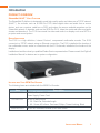
VIEW® Pro - E120 Digital AV Encoder
Installation and User Manual
AVoIP™
ClearOne
5225 Wiley Post Way
Suite 500
Salt Lake City, UT 84116
Telephone 1.800.283.5936
1.801.974.3760
FAX
1.801.303.5711
E-mail
On the Web
[email protected]
www.clearone.com
VIEW Pro E120 Installation Manual
ClearOne Document
DOC-0149-001- October, 2014 (Rev. 1.0)
© 2014 ClearOne All rights reserved. No part of this document
may be reproduced in any form or by any means without written
permission from ClearOne. ClearOne reserves specific privileges.
Information in this document is subject to change without notice.
Table of Contents
INTRODUCTION
Product Overview..................................................................................................................................................... 1
StreamNet AVoIP™ Video Platform....................................................................................................................................1
Device Application..............................................................................................................................................................1
Included with Your VIEW Pro Encoder................................................................................................................................1
CONNECTIONS
Inputs and Connections.......................................................................................................................................... 2
Status LED..........................................................................................................................................................................2
10/100/1000 Ethernet Jack................................................................................................................................................2
HDMI Inputs........................................................................................................................................................................3
IR In....................................................................................................................................................................................3
IR Out .................................................................................................................................................................................3
RS-232 (COM)....................................................................................................................................................................3
19VDC Input.......................................................................................................................................................................3
INSTALLATION
Physical Characteristics.......................................................................................................................................... 4
Dimensions (Excluding Connectors)..................................................................................................................................4
Mounting the E120................................................................................................................................................... 4
The E120 in a Network............................................................................................................................................. 6
Connecting the E120................................................................................................................................................ 6
SOFTWARE SETUP OF THE E120
LUA File.................................................................................................................................................................... 7
E120 Screens in the Dealers Setup Program......................................................................................................... 8
Adding an E120 to a Project..............................................................................................................................................8
The Information Tab..........................................................................................................................................................10
The Sources Tab...............................................................................................................................................................11
The Sources Tab Advanced Configuration......................................................................................................................12
Editing a Stream..........................................................................................................................................................13
Premium Features.......................................................................................................................................................15
Editing Stream Presets................................................................................................................................................15
Video Presets.......................................................................................................................................................16
Audio Presets.......................................................................................................................................................18
The GPIO Settings Tab.....................................................................................................................................................20
Input Macro Assignments...........................................................................................................................................20
Relay Assignments......................................................................................................................................................20
VIEW PRO RS-232 CONTROL
LUA File Driver Templates..................................................................................................................................... 21
Preparing the New One-Way RS-232 Driver File.................................................................................................. 21
Preparing the Encoder/Decoder........................................................................................................................... 23
Modifying the One-Way Driver File....................................................................................................................... 24
VIEW PRO AND VIEW LEGACY INTEROPERABILITY
Control Sharing...................................................................................................................................................... 29
Audio Streaming Interoperability.......................................................................................................................... 29
IR Learning and Control........................................................................................................................................ 30
Firmware Upgrading.............................................................................................................................................. 30
VIEW PRO ACCESSORY KITS
Kit Descriptions...................................................................................................................................................... 31
COMPLIANCE
Compliance Overview............................................................................................................................................ 32
RoHS Compliance............................................................................................................................................................32
Stainability........................................................................................................................................................................32
Electrical Safety Advisory...................................................................................................................................... 32
Compliance Details................................................................................................................................................ 32
FCC Compliance..............................................................................................................................................................32
European Compliance.....................................................................................................................................................32
SERVICE AND SUPPORT
Technical Support.................................................................................................................................................. 33
Sales....................................................................................................................................................................... 33
Techsales................................................................................................................................................................ 33
Product Returns..................................................................................................................................................... 33
Introduction
PRODUCT OVERVIEW
StreamNet AVoIP™ Video Platform
The StreamNet IP platform is designed to send high-quality audio and video over a TCP/IP network
(AVoIP™). An encoder, such as a VIEW Pro E120, takes digital video and audio from a source
device, such as a receiver, cable box or DVR, and makes the source available anywhere on the
StreamNet network. A decoder, such as the VIEW Pro D110, takes the combined video and audio
stream and decodes it. The D110 then sends the video and audio to a display such as a HDTV or
projector and sound system.
Device Application
The E120 is a high definition, Internet Protocol, compressed multimedia encoder. The E120
connects to a TCP/IP network using an Ethernet connection. The E120, installed at the location of
the multimedia source, works in connection with the D110 decoder, installed at the location of the
display.
Installation should be done by a qualified Dealer Service representative. Please consult the DigiLinX
Installation Manual for device use in system configuration.
Included with Your VIEW Pro Encoder
The following items are included with the VIEW Pro Encoder:
Item
910-0000-001
Description
VIEW Pro Encoder E120
910-0002-001
Power Supply, Power Cord
VIEW Pro Rack Mount
• 2X - Rack Ear, Extended length
QSG-0010-001
• 6X - Screw, M3 x 6mm, Pan-head, Philips, Thread Locking, Black
VIEW PRO Encoder/Decoder Quick Start Guide
Installation Manual
1
Connections
The VIEW Pro E120 Encoder has the following input and output connectors on the back of the unit.
• 1x - IR Input connector compatible with SteamNet IR sensor (3.5mm)
• 1x - IR Input Receiver window on front panel
• 1x - IR Output connector compatible with SteamNet IR emitter (3.5mm)
• 2x - Balanced Audio Input (Two Modular Phoenix-type connectors, left and right)
• 3x - GPIO (General Purpose Inputs - Digital, 0/5V, Phoenix-type)
• 3x - GPIO (General Purpose Outputs - Latching, Relays, Phoenix-type)
• 1x - Stereo 3.5mm Barrel Plug (Line Level) Input
• 1x - Stereo 3.5mm Barrel Plug (Line Level) Output (Currently not used)
• 2x - HDMI-input connectors.
• 2X - RS-232 DB-9 connector
• 2x - RJ45 10/100/1000 Mb Ethernet jack (Use only jack 1)
• 3x - USB connectors (one USB connector on front panel not visible)
• 1x - 19V DC Power Connector
INPUTS AND CONNECTIONS
The E120 transmits the digital video and audio on the network.
Status LED
An LED on the front panel lights up when the unit is powered and to report status:
• Off=Off
• Yellow=Update process has started (e.g.: Update Devices)
• Blue=Normal Operation
• Green=System Startup/shutdown
• Red=Error Condition
10/100/1000 Ethernet Jacks
The 10/100/1000 Mb Ethernet connector allows connection to TCP/IP networks setup to run
StreamNet. Only Port 1 (Red Jack) is supported. The other is a service port that MUST NOT be
connected.
2
Technical Support: 800.283.5936
HDMI Inputs
The HDMI connectors on the E120 receive digital video and audio.
IR In
This jack allows connection of an StreamNet compatible infrared receiver. The infrared receiver can
pick up IR remote control signals for IR learning.
IR Out
This jack allows connection of an infrared transmitter. The infrared transmitter can send IR remote
control signals.
RS-232 (COM)
These jacks allow the E120 to control a source, or other connected source device. They support
sending and receiving RS-232 commands to control devices.
19VDC Input
This connector provides power input for the E120. This power is available using the included power
supply.
Installation Manual
3
Installation
PHYSICAL CHARACTERISTICS
Dimensions (Excluding Connectors)
Width: 12.2 inches (310mm)
Length: 7.4 inches (188mm)
Height: 1.75 inch (44.4mm)
MOUNTING THE E120
The VIEW Pro encoder includes a Rack Mount Kit (910-0002-001) with rack-mount ears that attach
to the encoder to facilitate mounting in a standard rack.
Surfacemounted,
Mounting
When
the I/O connections are accessible from the back of the unit. (If needed, the unit
can also mount with the I/O connections facing the front of the rack.)
Rack Mounting
Surface Mounting
The VIEW Pro encoder can also be surface mounted using the optional Wall Mount Kit (910-0002002) with surface-mount ears that attach to the encoder to facilitate mounting.
An optional VESA mount bracket Kit (910-0002-006) is available for applications where an encoder
must be located on a VESA mount.
Rack Mounting
VESA Bracket
4
Technical Support: 800.283.5936
Wall Bracket
(Mount to stud or
other solid surface)
Unit with VESA Bracket
hangs on Wall Bracket
There may some situations where the VIEW Pro cables cannot be concealed within a cabinet or in a
wall. These cables can be surface mounted and concealed using the optional 910-0002-003 VIEW
Pro Cable Raceway Kit. This raceway, in 12-inch joinable lengths, can be mounted to the wall to
secure and cover the cables to the VIEW Pro devices.
Use included wire ties to secure
the cables to the wall bracket
Mount the wall brackets
to a solid surface.
(Wall screws not included)
Make 11 inch spacing between
top and bottom bracket mounting holes
The metal cover snaps onto
the wall-mounted brackets
Edge protectors prevent
cover from making contact with the cables.
Two sections or more kits may be combined to make a longer raceway. Join them using the included spring pins.
The metal cover may be cut to size as needed.
Installation Manual
5
THE E120 IN A NETWORK
The VIEW Pro E120 encoder takes digital video and audio from source devices such as media/disc
players, cable/satellite boxes, DVRs, and cameras, and then makes the digital video and audio
available anywhere on the StreamNet® IP network. a StreamNet TCP/IP network using a standard
10/100/1000 Mbit Ethernet connection. The VIEW Pro decoders, as counterparts, are installed at
the locations of the target video displays. They operate together: the encoders providing the IP
data for the decoders to deliver to the displays..
CONNECTING THE E120
The E120 Encoder connections are from the back of the unit as shown in the following diagram.
Left/Right
Balanced
Inputs
6 GPIO Ports
for Control
3 Inputs and
3 Outputs
COM2 Port for
Source/3rd-Party
Device Control
2 HDMI
Audio/Video Port
COM1 Port for
Source/3rd-Party
Device Control
Power
On/Off
3.5mm IR Input
IR Learning
6
3.5mm IR
19 VDC
2 x USB
Network Port2
Network Port1
3.5mm Audio
3.5mm Line-level
(Currently Not Used)
Output for
Input from 3.0 Ports
Output for Line-level
Audio Input
Source Display Power
for USB
Audio or Digital
or 3rd-Party
Adapter Audio/Video
Audio Output
(Currently Not Used)
Control
Devices
Technical Support: 800.283.5936
DSP forced
air intake
Software Setup of the E120
The E120 is setup for use in a commercial or residential network using the StreamNet Dealer Setup
program and the accompanying StreamNet Dealer Setup manual. StreamNet Dealer Setup is a
PC-based program that allows you to configure devices so that they can communicate across a
StreamNet network. Phases of the software setup include:
• Adding or creating a new project or opening an existing project
• Finding the new device
• Matching the new E120 physical hardware device to the hardware setup in the project
• Configuring the device with system-specific information
• Saving the project
• Sending the configuration files to the devices
The steps involved in these processes are detailed in the DigiLinX Dealer Setup manual available
for viewing or download at www.ClearOne.com.
LUA FILE
Control options for VIEW Pro devices using StreamNet Dealer Setup is facilitated but the .lua file
found in the C:\Program Files x86)\ClearOne\StreamNet Application Suite\viewPro\drivers directory
VIEW Pro has two DB9 Serial ports available on both Encoder and Decoder.
Information about editing and using .lua files for RS-232 control is included in the VIEW Pro RS-232
Control section later in this manual.
Installation Manual
7
E120 SCREENS IN THE DEALER SETUP PROGRAM
Verify the configuration information on the tabs for the E120 device as shown in the following screen
examples:
Adding an E120 to a Project
8
Technical Support: 800.283.5936
1. Enter the following information:
Device Name - Edit to name the E120 Device.
Model Number - Select the E120 Device.
2. Enter the following information:
GPIO Name - This is mainly used in macros By default this receives the Device Name.
Source Names - Edit to name sources. (There are two HDMI Audio/Video and two AnalogOnly Audio (Balanced, UnBalanced) sources available for the E120.)
»» NOTE: Whatever you type in for each source name here will appear in the list
of sources on the TouchLinX touch panel interface and VIEW Virtual Matrix.
Source Type - Use the drop-down list (using the down arrow key) to select what type of source
this is for each named source. The source type brings up the appropriate controls for the
source. There are several types of sources.
»» NOTE: Source type parameters and definitions that are used in StreamNet
networks are contained in .lua driver files. Customized types can be created
using existing files as templates, editing them as desired, and saving as a
new type that is then available for use by the VIEW Pro. For more information
regarding creating an using template files, see the Using Templates section
later in this document
3. Select Save & Continue
4. Complete the information for each E120 in your project.
Installation Manual
9
The Information Tab
The Information tab contains all of the information about that particular A/V device:
Current IP Address - The current IP address of the E120.
Current Subnet Mask - The current subnet mask of the E120.
Device Type - The type of device that this is.
Model Number - The E120 model number.
Firmware Version - What firmware version is currently running on the E120.
Device Name - Descriptive name assigned to the device when creating the project.
Serial Number - Displays the E120 serial number.
Device Comments - Indicate where the device is installed so that if you need to return to the
installation for service or upgrading devices, you can have access to this information in the project
file.
10
Technical Support: 800.283.5936
The Sources Tab
The Sources tab contains all of the settings and information about the sources connected to the
E120:
There are two Audio/Video (HDMI) and two Analog sources available for the E120. Each one used
needs to be configured within the project.
Source Name - This name appears as a selection on all user interfaces and identifies the source.
Source Type - The type of source connected to the VIEW Pro. (May be selected from CD player,
DVD player, DVR, generic device, generic media server or cameras etc.)
Driver File - The new driver file for the video source. (Allows you to select the designated .lua
driver file. The ViewPro Lua files are stored in the ClearOne StreamNet Dealer Setup directory (C:\
Program Files (x86)\ClearOne\StreamNet Application Suite\viewPro\drivers).
»» NOTE: A replacement .lua file can be created from a template that will allow
customizing the VIEW Pro encoder/decoder to receive RS-232 commands
instead of IR. For more information regarding creating an using template
files, see the Using Templates section later in this document
Audio Source - Allows you to select what kind of audio input the VIEW Pro uses for this stream.
(May be selected from HDMI 1, HDMI 2, Balanced or Unbalanced.)
Installation Manual
11
Gain - The Audio Gain drop-down for setting the audio input gain up or down to match that of other
sources in the system. Select from ± 0, 3, or 6 dB amplification or attenuation of audio source.
Advanced Configuration - This button is unavailable and greyed out when any <Video Stream>
source Enable check box is selected. To enter Advanced Configuration, un-check the Enable check
boxes, and press the Apply button. Now the Advanced Configuration button is available
The Sources Tab Advanced Configuration
If all the <Video Stream> Enable check boxes are unchecked, advanced configuration is available
to specify the details of the source streams. Up to two Audio/Video streams can be defined as well
as multiple Audio-Only streams.
To open Advanced Configuration, click on the Advanced Configuration button on the bottom of
the screen in the Sources tab.
This screen allows the addition, editing and deletion of device streams for the encoder. When a new
stream is added, it can be selected to then edit the stream and edit the stream presets.
12
Technical Support: 800.283.5936
EDITING A STREAM
Click on the name of the stream you are editing, then click on Edit Stream.
On the Edit Stream screen you can select from preset characteristics for the stream.
Installation Manual
13
Audio Device – The physical input port for the audio stream.
Video Device – The physical input port for the video stream.
Audio Preset File – The audio preset file that is linked to this stream.
Video Preset File – The video preset file that is linked to this stream
Driver File – The lua driver that executes any source or 3rd-party commands coming from the
network to control the stream including IR.
»» NOTE: A replacement .lua file can be created from a template that will allow
customizing the VIEW Pro encoder/decoder to receive RS-232 commands instead
of IR. For more information regarding creating an using template files, see the
VIEW Pro RS-232 Control section later in this document.
Source Type – The type of source for the stream (CD, DVD, Tuner).
Gain - Sets the volume of the stream in the final mix. The Audio Gain drop-down for setting the
audio input gain up or down to match that of other sources in the system. Select from ± 0, 3, or 6
dB amplification or attenuation of audio.
Slave Service Names – The names of the lua/ir services in the system that handle ASCII control
commands.
Height – The display height of the stream in pixels.
Width – The display width of the stream in pixels.
Channels Count - Sets the number of audio channels that are present in the stream.
Max Allowed Latency - Sets the maximum latency the video stream allows, beyond which frames
will be dropped to avoid limit-less buffering.
Audio Only – makes the stream audio only, with no video present.
Framerate Slave - When turned on, the stream’s frame rate is dynamically controlled by the source
layout’s frame rate. Otherwise, the frame rate is set by these parameters.
Resolution Slave - When turned on, the stream’s resolution is dynamically controlled by the source
layout’s resolution. Otherwise, the resolution is set by these parameters.
Enable RTSP Stream - Decides whether the data will be available through a UNICAST RTSP
stream as well as the default proprietary stream.
Unicast RTSP Streaming means that every instance of the Stream selected by an RTSP Player
(e.g.: PotPlayer, VLC) will create a unique RTSP Stream from the Encoder. Three programs
trying to access this stream over RTSP will require the Encoder to create three instances of the
stream, which takes up resources within the Encoder and limits the number of Players that can
watch/listen to this stream.
14
Technical Support: 800.283.5936
PREMIUM FEATURES
Legacy Audio Support - This Premium Licensed Feature allows the creation of Audio-Only Streams
which can be selected and listened to using the ClearOne Legacy Renderers (SLxxx, VLxxx).
MultiCast RTSP Support - This Premium Licensed Feature allows an RTSP-compatible A/V or
audio-only stream to be created within the Encoder. When creating an Multicast RTSP stream, the
Basic Features box for Enable RTSP Stream must also be checked.
Multicast RTSP Streaming means that the Encoder will create only one instance of the A/V
or Audio Only Stream, and will send it to Players requesting a connection via Multicast. Any
number of Players can attach to this Stream without increasing bandwidth or processing loading
on the Encoder. Multicast RTSP requires Licensing, but any number of Players can join the
Stream without additional overhead CPU or Networking capacity being used due to the use of
the Multicast Networking.
EDITING STREAM PRESETS
User Video and Audio Presets can be created, deleted or edited for use in any stream configuration
to meet the requirements of the sources and encoder. Once a preset has been created it can be
assigned and enabled to any device stream.
»» NOTE: Dealer Setup comes with several pre-defined preset settings for video and
audio. These pre-defined presets can be used, but cannot be deleted nor edited;
only user-created presets can be changed or removed.
Click on the Edit Presets button to open the Preset Editor screen.
The Preset Editor screen has panels listing video and audio presets. Selecting a preset from either
of the panels presents the selected preset characteristics in the right hand panel.
Adding or Deleting of presets is done with the Add and Delete buttons. Click on the Edit Presets
button to open the Preset Editor screen.
The Preset Editor screen has panels listing video and audio presets. Selecting a preset from either
of the panels presents the selected preset characteristics in the right hand panel.
Adding or deleting of presets is done with the Add and Delete buttons.
Installation Manual
15
Video Presets
The following screen shows the “HD Video Distribution” in the Preset Editor with details on the right
hand panel.
16
Technical Support: 800.283.5936
Video Presets Descriptions
HD Video Distribution - Video Distribution containing high-definition content for large screen
high quality applications.
PC Presentation - Utilizes 4:4:4 Video at 24-bit color depth for maximum clarity.
RTSP Lan Mode - Optimized for Distributing RTSP video streams for LAN applications.
RTSP Wan Mode - Optimized for Distributing RTSP video streams for WAN applications.
Signage Active Content - Digital Signage containing embedded videos and/or rapid movement.
Signage - Digital Signage content containing mostly static images and text
Video Distribution - Distribution for high-definition content at a lower bandwidth for basic video
applications.
Setting Video Preset Values
Video Bitrate – Sets the desired video bitrate of the video (in Mbps).
Frame Rate – The output frame rate.
Allow Bandwidth Spikes – If checked, allows the stream to exceed the allotted bandwidth
momentarily, but not on average. Useful for LANs, reduces latency.
Use 444 Mode – Sets color sampling to 24 bits.
The pre-existing presets are set with these default values.
Video Presets
Signage Active Content
Signage
HD Video Distribution
Video Distribution
PC Presentation
RTSP LAN Mode
RTSP WAN Mode
Video Bitrate
(Mb/s)
60Mb
16Mb
60Mb
16Mb
60Mb
8Mb
2Mb
Frame Rate
60
60
60
60
60
60
60
Allow Bandwidth Spikes
Yes
Yes
Yes
Yes
Yes
No
No
Use 444
Mode
No
No
No
No
Yes
No
No
Installation Manual
17
Audio Presets
The following screen shows the “PCM High Bitrate” in the Preset Editor with details on the right
hand panel.
18
Technical Support: 800.283.5936
Audio Presets Descriptions
PCM High Bitrate - Configured for High Definition Movie and Video Distribution applications.
PCM Low Bitrate - Configured for Basic Digital Signage and Video Distribution applications.
RTSP Audio - Configured using AAC Audio required by most RTSP applications.
Setting Audio Preset Values
Audio Bitrate - Sets the bitrate in bps of the audio encoding. Select 32000. 96000, 128000, 192000
or 320000 bps.
Audio Codec - Sets the codec used for audio. acAAC means using AAC encoding, acPCM will
use PCM 16-bit uncompressed audio.
Sample Rate - Sets the sampling rate of the stream’s audio. Select 32000, 44100, 48000, 96000,
128000 or 192000 bps.
The pre-existing presets are set with these default values.
Audio Presets
PCM High Bitrate
PCM Low Bitrate
RTSP Audio
Audio Bitrate
192000
128000
128000
Audio Codec
acPCM
acPCM
acAAC
Sample Rate (kHz)
48000
44100
44100
Installation Manual
19
GPIO Settings Tab
This tab allows you to choose a macro associated with each input state: High/Open and Low/
Closed. The VIEW Pro macros are created and used in the same manner as the VIEW legacy
products. Refer to the Dealer Setup Manual, Chapter 11 Section 1 (11-1) for the “Favorites section,”
which explains macros in detail.
The GPIO Tab contains six GPIO components (3x Input Triggers and 3x Relays).
INPUT MACRO ASSIGNMENTS:
In the GPIO Tab you can select previously created Macros from the drop-down list for both or one
Input states High/Open and Low/Closed, these Macros are triggered based on the configured
state and State changes.
RELAY ASSIGNMENTS:
Each of the three relays can be set in three states: None, Normally Open and Normally Closed.
These relays can be triggered to change state between Normally Open and Normally Closed to
trigger an event with the connected devices (projector lifts, motorized screens, lighting, shades,
etc...). These relays can be triggered by system macros (found in Macro Builder) or via TCP/IP and/
or serial control commands.
20
Technical Support: 800.283.5936
VIEW Pro RS-232 Control
The VIEW Pro has two DB9 Serial ports available on both Encoder and Decoder. The function
and operation of the ports is defined in a .lua file used as a driver and implemented through
StreamNet Dealer Setup. These ports communicate RS-232 commands and can be used in the
following scenarios:
1. Input and/or Output Control.
2. Source Control.
3. Display Control
The VIEW Pro .lua files are stored in the ClearOne StreamNet Dealer Setup directory :
(C:\Program Files (x86)\ClearOne\StreamNet Application Suite\viewPro\drivers).
If both Serial ports are to be used, then the Serial Comm Port number will need to be specified in
each .lua File with a “1” or a “2” (port = “comm://default;baud=9600;bits=8;parity=0;stop=1”).
LUA FILE DRIVER TEMPLATES
Driver templates created from .lua files allow the installer to create drivers that can send RS-232
commands to a source. These commands are one-way only. They are NOT capable of receiving
messages from the source. This is the same level of control as using IR, but with a RS-232
connection. One-way driver templates are configured by modifying a supplied .lua file. These
instructions will guide you through this process and assume you are a trained StreamNet Installer
and have a working knowledge of Windows.
What you need:
• E120
• D110, D210
• DB9 Serial cable
• RS-232 controlled source
• DB9 Gender-bender (depends on source)
• Null Modem Cable or Adapter (depends on source)
PREPARING THE NEW ONE-WAY RS-232 DRIVER FILE
Driver templates can be found in <StreamNet Application Suite>\ViewPro>\Drivers. You will
need to copy and rename the appropriate driver template into <StreamNet Application Suite>\
ViewPro>\Drivers. If the Drivers folder does not already exist go ahead and create the folder and
copy the .lua file into it. Then rename the file. This will allow you to select the driver in Dealer Setup
and leave you a backup copy of the original template.
Installation Manual
21
For Example: If you are creating a one way RS-232 file for a DVD you would:
• Locate the Driver Template directory
(i.e. C:\Program Files (x86)\ClearOne\StreamNet Application Suite\viewPro\drivers)
• Copy the DVDTEMPLATE.LUA file into the Drivers folder that you created
• Rename the DVDTEMPLATE.LUA
22
In this example, we will call it TESTDVD.LUA
Technical Support: 800.283.5936
PREPARING THE ENCODER/DECODER
The next step is to configure the Encoder/Decoder device.
Add the Encoder/Decoder as you normally would. Do NOT choose a source type that is tied to a
specific manufacturer or product model. If you are in doubt choose the source type you would use
if this were and IR device. For this example, we would choose DVD.
Installation Manual
23
Once the device is added select the Sources tab for the Encoder/Decoder.
Change the Driver file from IR to your newly created driver. For this example, we would change the
driver file from IR to DVDTemplate.lua.
Now Apply your changes. The Encoder/Decoder is now configured to use your one-way Driver
file.
So far all you have applied is a renamed file. Now you need to modify the driver file to support your
source.
MODIFYING THE ONE-WAY DRIVER FILE
To modify a Driver Template you will need to use a text editor like Notepad. Notepad is included
in Windows XP and Vista. Next you’ll need the RS-232 Protocol for the source. This is normally
found on the manufacturer’s website. This document will tell you the communication settings, pin
connections, and the RS-232 commands.
24
Technical Support: 800.283.5936
In the RS-232 Protocol section of the .lua file, locate the communication settings. Normally these
settings will include: Baud rate, Data Bit, Stop Bit, and Parity. Once you find them you will need to
verify that these commands match those used in the driver file.
To do this, open the file in your text editor:
Do a text search for: baud=
You are looking for this line:
port = “comm://default;baud=9600;bits=8;parity=0;stop=1”,
Installation Manual
25
Verify that the baud, bits, parity, and stop values in the driver file match the settings listed in the RS232 Protocol. Most devices use Baud=9600, Data bits=8, Parity=0, and Stop bits=1.
Now locate the Command table in the driver file.
Do a text search for: local CmdTable =
26
Technical Support: 800.283.5936
Below the local CmdTable = text are the available commands where you can enter RS-232
commands. For each command you will enter the command between the quotation marks.
For example: To enter the RS-232 command for TUNE UP:
Locate the TUNE UP command line:
[‘TUNE UP’] = “”,
Add the appropriate RS-232 command for the source to do a TUNE UP between the quotes
[‘TUNE UP’] = “W 1 6 1”,
Note that in most RS-232 Protocols you are required to put a Carriage Return to indicate an end
of command. Use %0D to indicate a Carriage Return.
[‘TUNE UP’] = “W 1 6 1%0D”,
Installation Manual
27
Your table should begin looking like this:
Once you have completed your changes, save the file.
From Dealer Setup, send the configuration to your Encoder/Decoder.
The StreamNet GUI will now send the RS-232 command to the source via the DB9 port instead of
the IR.
28
Technical Support: 800.283.5936
VIEW Pro and VIEW Legacy Interoperability
There are several types of interoperability with VIEW Pro and the legacy VIEW products:
• Control Sharing
• Audio Streaming Interoperability
• IR Learning and Control
• Firmware Upgrading
CONTROL SHARING
From a command and control standpoint, VIEW legacy and VIEW Pro devices all appear and act
the same; that is, a TouchLinX Touch Panel, Virtual Control, and VIEW Virtual Matrix (VVM) can all be
used to control both types of products. Currently, command and control, and audio streams are
seamless between the products. For instance, a TouchLinX can control source selection for VIEW
Pro and StreamNet devices.
In StreamNet, Static Menus are menus that appear for selection in a particular room. Static Menus
can be created using VIEW Pro sources in the same manner as the legacy VIEW products. Refer
to Chapter 17 of the Dealer Setup Manual for “Using Static Menus.” This explains Static Menus in
detail.
The VIEW Virtual Matrix software (VVM) is a program interface that can be run on a PC or laptop
running Microsoft Windows 7. Unlike the room-centric based StreamNet virtual control software
GUI that is created by a dealer with the StreamNet Dealer Setup software, VVM Is a system-centric
control software GUI. This makes it much easier for you to control large systems, or control many
rooms on a single screen. In VVM the sources and destinations are differentiated by color for VIEW
legacy and VIEW Pro.
• Light Blue Color = VIEW Legacy Devices
• Light Green Color = VIEW Pro Devices
AUDIO STREAMING INTEROPERABILITY
A VIEW Pro Decoder can receive audio sourced from VIEW MLA100/101/9101/4000,
MLAV300/9300/9500, audio ports enabled for global selection, also iPOD Dock, and VL100/9100/9300
reverse audio.
Conversely, StreamNet Devices can play audio streams from a VIEW Pro Encoder. At this time, video
cannot be shared across the Products because they are using different compression schemes.
»» NOTE: Bridging Audio between VIEW Pro and StreamNet is a Licensed Feature. See
your ClearOne business contact for additional information.
Installation Manual
29
IR LEARNING AND CONTROL
The accessory kits for the IR Emitter and IR Receiver allow the use of these devices with the VIEW
Pro products. For example, an IR Emitter can be placed over the integrated IR Receiver of a display
so signals from the VIEW Pro can be used to control the display. An IR Receiver unit can be used to
receive and relay IR commands to a device placed out of the line of sight of the IR control device.
The VIEW Pro IR tools and IR learning are used in the same manner as the VIEW Legacy products.
Refer to Chapter 7 for the IR Tools section, first section (7-2) explains IR Learning in detail.
3.5mm IR Input
IR Learning
3.5mm IR
Output for
Source Display
or 3rd-Party
Control
Transmit
direction
IR Emitter
(Self adhesive)
Sensor
direction
IR Receiver
(Self adhesive)
FIRMWARE UPGRADING
VIEW Pro The devices can update their firmware in the same manner as the VIEW Legacy devices.
Refer to the Dealer Setup Manual, Chapter 3, Section 2 (3-2) for “Creating and Saving Projects,”
which explains the Firmware Update process in detail.
30
Technical Support: 800.283.5936
VIEW Pro Accessory Kits
KIT DESCRIPTIONS
The following accessory kits are available to meet the mounting and control needs of your VIEW
Pro Encoders and Decoders:
Part Number
910-0002-001
910-0002-002
910-0002-003
Kit Name
VIEW Pro Rack
Mount
Description
Rack Mount Kit for VIEW Pro Encoder E120, Decoder D110
(Included with
Encoder)
• 6X - Screw, M3 x 6mm, Pan-head, Philips, Thread Locking,
Black
Wall Mount Kit for VIEW Pro Encoder E120, Decoder D110
VIEW Pro Wall
Mount
• 2X - Rack Ear, Extended length
• Bracket 1Ru Rack/Wall Mount
(Included with
Decoder)
• 2X - Screw, M3 x 6mm, Pan-head, Phillips, Thread Locking,
Black
VIEW Pro Cable
Raceway
• 2X - Bracket, 19V PSU Wall mount
Cable Raceway Kit (12 inch) for Wall Mount Kit for VIEW Pro
Decoder D110
(Optional)
• 1X - Extrusion, Cable Raceway Cover, 12 inch
• 2X - Bracket, Cable Raceway Wall-mount Clip
• 2X - Cable Tie (4 inch)
• 2X - Spring Pin, 5-64 inch x 1 inch
910-0002-004
910-0002-005
VIEW Pro IR
Receiver
(Optional)
VIEW Pro IR
Receiver &
Emitter
(Optional)
910-0002-006
• 2X - Plastic, Edge Protector, 3 inch
IR Receiver cable for VIEW Pro Encoder E120, Decoder D110
• 1X - IR Receiver Assembly with 6 ft. cable
IR Receiver Cable, IR Emitter Cable Kit for VIEW Pro Encoder
E120, Decoder D110
• 1X - IR Receiver with 6 ft. cable, 3.5 mm plug
VIEW Pro VESA
bracket
• 1X - IR Emitter with 6 ft. cable, 3.5 mm plug
Wall Mount VESA Bracket Kit for VIEW Pro Encoder E120,
Decoder D110
(Optional)
• 1X - Bracket, VESA and Hanging Mount
• 1X - Bracket, Wall Side Mount
• 2X - Bracket, 19V PSU Wall mount
• 4X - Screw, M4 X 6mm, Pan-Head, Phillips, Plain
Installation Manual
31
Compliance
COMPLIANCE OVERVIEW
RoHS Compliance
All components and processes used to produce the E120 will comply with the RoHS initiative.
Sustainability
The E120 is compliant with the WEEE recycling initiative. It is made from easily recyclable materials such as aluminum and steel.
ELECTRICAL SAFETY ADVISORY
This equipment uses DC power supplied from an external source which can be subjected to
electrical surges, typically lightning transients which are very destructive to customer terminal
equipment. The warranty for this equipment does not cover damage caused by electrical surge or
lightning transients. To reduce the risk of this equipment becoming damaged it is suggested that
the customer consider installing a surge arrestor.
Any modifications to the device without express authorization from ClearOne is prohibited as per
47CFR15.21 and could void the users authority to operate the device.
COMPLIANCE DETAILS
FCC Compliance
FCC Part 15: This device complies with FCC Part 15 regulations for a Class A device.
»» NOTE: This Class A device complies with Part 15 of the FCC rules and Canadian
ICES-003. Operation is subject to the following two conditions: (1) this device may
not cause harmful interference, and (2) this device must accept any interference
received, including interference that may cause undesired operation.
European Compliance
Details on European equipment compliance can be found on the ClearOne website.
32
Technical Support: 800.283.5936
Service and Support
If you need assistance setting up or operating your product, please contact us. We welcome your
comments so we can continue to improve our products and better meet your needs.
Technical Support
Telephone:1.800.283.5936
E-mail:
[email protected]
Web site:
www.ClearOne.com
Sales
Telephone:1.800.707.6994
E-mail:
Techsales
[email protected]
Telephone:1.800.705.2103
E-mail:
[email protected]
Product Returns
All product returns require a Return Material Authorization (RMA) number. Contact ClearOne
Technical Support before returning your product. Make sure you return all the items and packing
materials that originally shipped with your product.
AVOIP™
HEADQUARTERS:
Salt Lake City, UT USA
5225 Wiley Post Way
Suite 500
Salt Lake City, UT 84116
EMEA
Tel: +44.1454.616.977
e-mail: [email protected]
APAC
Tel: +011.852.3590.4526
e-mail: [email protected]
LATAM
Tel: 801.974.3621
e-mail: [email protected]
TechSales
Tel: 800.705.2103
e-mail: [email protected]
Technical Support
Tel: 800.283.5936
e-mail: [email protected]
Tel: 801.975.7200
Toll Free: 800.945.7730
Fax: 801.303.5711
e-mail: [email protected]
Installation Manual
33