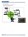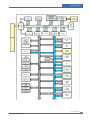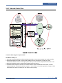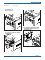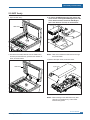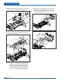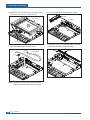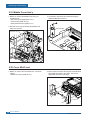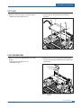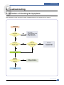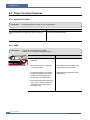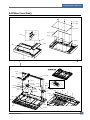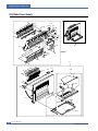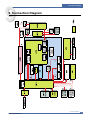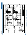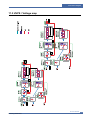
1
DIGITAL LASER MFP SCX-5X30 Series SCX-5530FN/XAZ Basic Model : SCX-5530FN SERVICE DIGITAL LASER PRINT Manual The keynote of Product [Key Features] - 28 ppm Print speed/20 cpm Copy Speed (Printing Speed: A4/28ppm,Letter/30ppm) - 1200 dpi Print Resolution (Addressable) - PCL6, PS3(SCX-5530FN) - CPU: Chorusm - Network Solution: Scan-to-Email, Scan-to-SMB, Scan-to-FTP - 64MB System Memory/32MB DIMM(5530FN) - 50 ADF / MP 50 Sheet - 250 sh Paper Input / 150 sh Paper Output - 33.6 Kbps Fax Modem (5530FN only) - Duplex Print (5530FN only) - Direct USB Connectivity 2nd Version (PDF Direct Printing) (5530FN only) - Small Foot Print - Toner: 4K(Initial)/ 8K(sales) Contents 1. Precautions 1.1 1.2 1.3 1.4 Safety Warning Caution for safety ESD Precautions Super Capacitor or Lithium Battery Precautions 1-1 1-2 1-5 1-5 2. Product Specification 2.1 2.2 2.3 2.4 2.5 Product Overview Product General Specifications Model Comparison Table ACCESSROY Options 2-1 2-2 2-7 2-7 2-8 3. System Overview 3.1 3.2 3.3 3.4 System Construction Mechanical Parts Specifications Engine F/W S/W Descriptions 3-1 3-8 3-31 3-34 4. Alignment and Adjustments 4.1 4.2 4.3 4.4 4.5 4.6 4.7 4.8 Paper path Clearing Paper Jams User Mode Tech Mode Identify Sale Date Consumables and Replacement Parts Abnormal Image Printing and Defective Roller Display LED and Error Messages 4-1 4-2 4-8 4-14 4-23 4-24 4-25 4-26 Continued 5. Disassembly and Reassembly 5.1 General Precautions on Disassembly 5.2 Disassembly and Reassembly 5-1 5-2 6. Troubleshooting 6.1 6.2 6.3 6.4 6.5 6.6 6.7 6.8 6.9 Procedure of Checking the Symptoms Paper Feeding Problems Printing Problems (malfunction) Printing Quality Problems Fax & Phone Problems Copy Problems Scanning Problems Toner Cartridge Service Network Problems Troubleshooting 6-1 6-2 6-6 6-12 6-19 6-23 6-25 6-26 6-30 7. Exploded Views & Parts List 7.1 Main Exploded Views 7.2 Cover Ass'y 7.3 Middle Cover Ass'y 7.4 Front Cover Ass'y 7.5 Rear Cover Ass'y 7.6 Frame Assembly 7.7 Fuser Drive Ass'y 7.8 Main Drive Ass’y 7.9 MP Ass'y 7.10 Scan Ass'y 7.11 Platen Ass'y 7.12 Cover Platen Ass'y 7-2 7-4 7-6 7-8 7-10 7-12 7-16 7-18 7-20 7-22 7-24 7-26 Continued 7.14 7.15 7.16 7.17 OPE Unit Cassette Ass'y Fuser Ass’y Duplex Unit(Optional) 7-31 7-33 7-35 7-37 8. Block diagram 9. Connection Diagram 10. Schematic Diagram 10.1 10.2 10.3 10.4 Schematic Main DIMM board CRUM board OPE_3in1 OPE_4in1 10.5 HVPS 10.6 SMPS_V1 SMPS_V2 10.7 SCF 10.8 ADF PBA 10.9 Modem 10.10 Connection 10.11 Terminal 10-1 10-16 10-18 10-19 10-20 10-21 10-24 10-25 10-26 10-28 10-29 10-33 10-34 11. Power Signal 11.1 Main Board Power signal 11.2 OPE / ADF Power signal 11.3 HVPS / Voltage map 11-1 11-2 11-3 Continued 12. Reference Information 12.1 12.2 12.3 12.4 Tool for Troubleshooting Acronyms and Abbreviations The Sample Pattern for the Test Wireless LAN 12-1 12-2 12-3 12-4 1 Precautions 1. Precautions In order to prevent accidents and to prevent damage to the equipment please read the precautions listed below carefully before servicing the printer and follow them closely. 1.1 Safety Warning (1) Only to be serviced by appropriately qualified service engineers. High voltages and lasers inside this product are dangerous. This printer should only be serviced by a suitably trained and qualified service engineer. (2) Use only Samsung replacement parts There are no user serviceable parts inside the printer. Do not make any unauthorized changes or additions to the printer, these could cause the printer to malfunction and create electric shock or fire haz-ards. (3) Laser Safety Statement The Printer is certified in the U.S. to conform to the requirements of DHHS 21 CFR, chapter 1 Subchapter J for Class 1(1) laser products, and elsewhere, it is certified as a Class I laser product con-forming to the requirements of IEC 825. Class I laser products are not considered to be hazardous. The laser system and printer are designed so there is never any human access to laser radiation above a Class I level during normal operation, user maintenance, or prescribed service condition. Warning >> Never operate or service the printer with the protective cover removed from Laser/Scanner assembly. The reflected beam, although invisible, can damage your eyes. When using this product, these basic safety pre-cautions should always be followed to reduce risk of fire, electric shock, and injury to persons. CAUTION - INVISIBLE LASER RADIATION WHEN THIS COVER OPEN. DO NOT OPEN THIS COVER. VORSICHT - UNSICHTBARE LASERSTRAHLUNG, WENN ABDECKUNG GE FFNET. NICHT DEM STRAHL AUSSETZEN. ATTENTION - RAYONNEMENT LASER INVISIBLE EN CAS D OUVERTURE. EXPOSITION DANGEREUSE AU FAISCEAU. ATTENZIONE - RADIAZIONE LASER INVISIBILE IN CASO DI APERTURA. EVITARE L ESPOSIZIONE AL FASCIO. PRECAUCION - RADIACION LASER IVISIBLE CUANDO SE ABRE. EVITAR EXPONERSE AL RAYO. ADVARSEL. - USYNLIG LASERSTR LNING VED BNING, N R SIKKERHEDSBRYDERE ER UDE AF FUNKTION. UNDG UDSAETTELSE FOR STR LNING. ADVARSEL. - USYNLIG LASERSTR LNING N R DEKSEL PNES. STIRR IKKE INN I STR LEN. UNNG EKSPONERING FOR STR LEN. VARNING - OSYNLIG LASERSTR LNING N R DENNA DEL R PPNAD OCH SP RREN R URKOPPLAD. BETRAKTA EJ STR LEN. STR LEN R FARLIG. VARO! - AVATTAESSA JA SUOJALUKITUS OHITETTAESSA OLET ALTTIINA N KYM TT M LLE LASERS TEILYLLE L KATSO S TEESEEN. Service Manual Samsung Electronics 1-1 Precautions 1.2 Caution for safety 1.2.1 Toxic material This product contains toxic materials that could cause illness if ingested. (1) If the LCD control panel is damaged it is possible for the liquid inside to leak. This liquid is toxic. Contact with the skin should be avoided, wash any splashes from eyes or skin immediately and contact your doctor. If the liquid gets into the mouth or is swallowed see a doctor immediately. (2) Please keep toner cartridges away from children. The toner powder contained in the toner cartridge may be harmful and if swallowed you should contact a doctor. 1.2.2 Electric Shock and Fire Safety Precautions Failure to follow the following instructions could cause electric shock or potentially cause a fire. (1) Use only the correct voltage, failure to do so could damage the printer and potentially cause a fire or electric shock. (2) Use only the power cable supplied with the printer. Use of an incorrectly specified cable could cause the cable to overheat and potentially cause a fire. (3) Do not overload the power socket, this could lead to overheating of the cables inside the wall and could lead to a fire. (4) Do not allow water or other liquids to spill into the printer, this can cause electric shock. Do not allow paper clips, pins or other foreign objects to fall into the printer these could cause a short circuit leading to an electric shock or fire hazard.. (5) Never touch the plugs on either end of the power cable with wet hands, this can cause electric shock. When servicing the printer remove the power plug from the wall socket. (6) Use caution when inserting or removing the power connector. The power connector must be inserted completely otherwise a poor contact could cause overheating possibly leading to a fire. When removing the power connector grip it firmly and pull. (7) Take care of the power cable. Do not allow it to become twisted, bent sharply round corners or other wise damaged. Do not place objects on top of the power cable. If the power cable is damaged it could overheat and cause a fire or exposed cables could cause an electric shock. Replace a damaged power cable immediately, do not reuse or repair the damaged cable. Some chemicals can attack the coating on the power cable, weakening the cover or exposing cables causing fire and shock risks. (8) Ensure that the power sockets and plugs are not cracked or broken in any way. Any such defects should be repaired immediately. Take care not to cut or damage the power cable or plugs when moving the machine. (9) Use caution during thunder or lightening storms. Samsung recommend that this machine be disconnected from the power source when such weather conditions are expected. Do not touch the machine or the power cord if it is still connected to the wall socket in these weather conditions. (10) Avoid damp or dusty areas, install the printer in a clean well ventilated location. Do not position the machine near a humidifier. Damp and dust build up inside the machine can lead to overheating and cause a fire. (11) Do not position the printer in direct sunlight. This will cause the temperature inside the printer to rise possibly leading to the printer failing to work properly and in extreme conditions could lead to a fire. (12) Do not insert any metal objects into the machine through the ventilator fan or other part of the casing, it could make contact with a high voltage conductor inside the machine and cause an electric shock. 1-2 Service Manual Samsung Electronics Precautions 1.2.3 Handling Precautions The following instructions are for your own personal safety, to avoid injury and so as not to damage the printer (1) Ensure the printer is installed on a level surface, capable of supporting its weight. Failure to do so could cause the printer to tip or fall. (2) The printer contains many rollers, gears and fans. Take great care to ensure that you do not catch your fingers, hair or clothing in any of these rotating devices. (3) Do not place any small metal objects, containers of water, chemicals or other liquids close to the printer which if spilled could get into the machine and cause damage or a shock or fire hazard. (4) Do not install the machine in areas with high dust or moisture levels, beside on open window or close to a humidifier or heater. Damage could be caused to the printer in such areas. (5) Do not place candles, burning cigarettes, etc on the printer, These could cause a fire. 1.2.4 Assembly / Disassembly Precautions Replace parts carefully, always use Samsung parts. Take care to note the exact location of parts and also cable routing before dismantling any part of the machine. Ensure all parts and cables are replaced correctly. Please carry out the following procedures before dismantling the printer or replacing any parts. (1) Check the contents of the machine memory and make a note of any user settings. These will be erased if the mainboard or network card is replaced. (2) Ensure that power is disconnected before servicing or replacing any electrical parts. (3) Disconnect printer interface cables and power cables. (4) Only use approved spare parts. Ensure that part number, product name, any voltage, current or temperature rating are correct. (5) When removing or re-fitting any parts do not use excessive force, especially when fitting screws into plastic. (6) Take care not to drop any small parts into the machine. (7) Handling of the OPC Drum - The OPC Drum can be irreparably damaged if it exposed to light. Take care not to expose the OPC Drum either to direct sunlight or to fluorescent or incandescent room lighting. Exposure for as little as 5 mins can damage the surface’s photoconductive properties and will result in print quality degradation. Take extra care when servicing the printer. Remove the OPC Drum and store it in a black bag or other lightproof container. Take care when working with the covers(especially the top cover) open as light is admitted to the OPC area and can damage the OPC Drum. - Take care not to scratch the green surface of OPC Drum Unit. If the green surface of the Drum Cartridge is scratched or touched the print quality will be compromised. Service Manual Samsung Electronics 1-3 Precautions 1.2.5 Disregarding this warning may cause bodily injury (1) Be careful with the high temperature part. The fuser unit works at a high temperature. Use caution when working on the printer. Wait for the fuser to cool down before disassembly. (2) Do not put finger or hair into the rotating parts. When operating a printer, do not put hand or hair into the rotating parts (Paper feeding entrance, motor, fan, etc.). If do, you can get harm. (3) When you move the printer. This printer weighs 17.5kg including toner cartridge and cassette. Use safe lifting and handling techniques. Use the lifting handles located on each side of the machine. Back injury could be caused if you do not lift carefully. (4) Ensure the printer is installed safely. The printer weighs 17.5Kg, ensure the printer is installed on a level surface, capable of supporting its weight. Failure to do so could cause the printer to tip or fall possibly causing personal injury or damaging the printer. (5) Do not install the printer on a sloping or unstable surface. After installation, double check that the printer is stable. 1-4 Service Manual Samsung Electronics Precautions 1.3 ESD Precautions Certain semiconductor devices can be easily damaged by static electricity. Such components are commonly called “Electrostatically Sensitive (ES) Devices”, or ESDs. Examples of typical ESDs are: integrated circuits, some field effect transistors, and semiconductor “chip” components. The techniques outlined below should be followed to help reduce the incidence of component damage caused by static electricity. Caution >>Be sure no power is applied to the chassis or circuit, and observe all other safety precautions. 1. Immediately before handling a semiconductor component or semiconductor-equipped assembly, drain off any electrostatic charge on your body by touching a known earth ground. Alternatively, employ a commercially available wrist strap device, which should be removed for your personal safety reasons prior to applying power to the unit under test. 2. After removing an electrical assembly equipped with ESDs, place the assembly on a conductive surface, such as aluminum or copper foil, or conductive foam, to prevent electrostatic charge buildup in the vicinity of the assembly. 3. Use only a grounded tip soldering iron to solder or desolder ESDs. 4. Use only an “anti-static” solder removal device. Some solder removal devices not classified as “anti-static” can generate electrical charges sufficient to damage ESDs. 5. Do not use Freon-propelled chemicals. When sprayed, these can generate electrical charges sufficient to damage ESDs. 6. Do not remove a replacement ESD from its protective packaging until immediately before installing it. Most replacement ESDs are packaged with all leads shorted together by conductive foam, aluminum foil, or a comparable conductive material. 7. Immediately before removing the protective shorting material from the leads of a replacement ESD, touch the protective material to the chassis or circuit assembly into which the device will be installed. 8. Maintain continuous electrical contact between the ESD and the assembly into which it will be installed, until completely plugged or soldered into the circuit. 9. Minimize bodily motions when handling unpackaged replacement ESDs. Normal motions, such as the brushing together of clothing fabric and lifting one’s foot from a carpeted floor, can generate static electricity sufficient to damage an ESD. 1.4 Super Capacitor or Lithium Battery Precautions 1. Exercise caution when replacing a super capacitor or Lithium battery. There could be a danger of explosion and subsequent operator injury and/or equipment damage if incorrectly installed. 2. Be sure to replace the battery with the same or equivalent type recommended by the manufacturer. 3. Super capacitor or Lithium batteries contain toxic substances and should not be opened, crushed, or burned for disposal. 4. Dispose of used batteries according to the manufacture’s instructions. Service Manual Samsung Electronics 1-5 2 Product Specifications 2. Product Specifications Specfications are correct at the time of printing. Product specifications are subject to change without notice. See below for product specifications. 2.1 Product Overview Model - SCX-5330N(3 in 1) : Copier, Printer, Scan - SCX-5530FN(4 in 1) : Copier, Printer, Scan, Fax Concept: MFP of high speed Target User : Small & Medium Business Customer Benefits (Sales Points) - Fast Printing Speed (28ppm in A4 / 30ppm in Letter) - Multifunction Network Solution (Scan-to-Email, Scan-to-SMB, Scan-to-FTP) - Duplex Capability(SCX-5530FN only) - Direct USB Connectivity 2nd Version (PDF Direct Printing) - Small Foot Print Key Features - 28 ppm Print speed/20 cpm Copy Speed - 1200 dpi Print Resolution (Addressable) - PCL6, PS3 - 64MB System Memory - 50 ADF - 250 sh Paper Input / 150 sh Paper Output - 33.6 Kbps Fax Modem - Duplex Print Service Manual Samsung Electronics 2-1 Product Specifications 2.2 Product General Specifications Items Series Model SCX-5330N General Major Features As Standalone: Copier, Printer, Scan Remarks SCX-5530FN As Standalone: Copier, Printer, Scan, Scan to USB, Fax As Network connected: Network Print, Network Scan, Scan to E-mail, Scan to SMB, Scan to FTP 435 450 mm (17.7 Size (W*D*H) w/o Hand Set 460 Net Weight(Inc. Toner Cartridge) 17.5 Kg (38.6 lbs) Net Weight(exc. Toner Cartridge) 15.7kg 17.1 18inch) Gross Weight(with package) 21.7kg LCD 16*2 Char(Export common) I/O Interface IEEE 1284/ USB 2.0/ Ehternet 10/100 base Tx (Embedded type) MPU CHORUSm / 300MHz Power Printing Operation Less than 520W Consumption Sleep Mode Less than 30W Power Switch Yes Power Supply Input Voltage Low Voltage : 110 ~ 127VAC (w/o backlight) System Bus 100MHz High Voltage : 220 ~ 240VAC Input Frequency 50 / 60Hz(+/- 3Hz) Printing 54dBA Copy 55dBA Standby 39dBA Warm Up Time from Cold Status Less than 20 seconds , Cold warm-Up time : 25sec Machine Life Max. Monthly Print 25,000 pages Volume(Duty Cycle) Scan 2,000 pages ADF 3,000 pages Noise Machine Life 250,000 pages Periodic Pickup Roller 150,000 Pages Replacing Pad Unit (Tray) 250,000 pages Pad Unit (ADF) 20,000 Pages Transfer Roller 70,000 Pages Fuser Unit 80,000 Pages Standard / Max. 64MB / 192MB(Std./Max) 92MB / 192MB(Std./Max) Type SDRAM SDRAM Expand Memory Slot , Type SDRAM DIMM Compression Technology YES Device Memory 2-2 Expand Memory specification would be defined separate note. Service Manual Samsung Electronics Product Specifications Items Series Model SCX-5330N PRINT SCAN Remarks SCX-5530FN Print Speed Simplex30ppm/Ltr, 28ppm/A4 (600 dpi) Print Speed(Duplex) N/A 21ipm/Ltr, 19ipm/A4 (600dpi) Print Emulation PCL6 PCL6, PS3 Auto Emulation Sensing YES Font Type 45 Scalable, 1 Bitmap Power Save Yes (5/10/15/30/45min.) Resolution Normal(Up to 1200dpi Effective Output(Addressable 1200x1200dpi)) Toner Save Yes Memory 16MB FPOT(From Stand by) Less than 8.5 sec ( From Ready ) Duplex Print N/A Printable Area 208 x 273 mm (Letter) Halftone(Gray Scale) 256levels Scan Method Yes Color CCD Scan Speed Linearity Approx. 15sec (USB 2.0) through ADF Gray Approx. 20sec (USB 2.0) Color Approx. 30sec (USB 2.0) Scan Speed Linearity Approx. 15sec (USB 2.0) through Platen Gray Approx. 20sec (USB 2.0) Color 75dpi /300dpi Approx. 30sec (USB 2.0) Optical 600*1200dpi Enhanced 4800dpi*4800dpi Resolution 75, 300, 600dpi horizontal Halftone 256level Scan Size(Max. Document Width) Max.216mm(8.5") Scan Size(Effective Scan Width) Max 208mm(8.2inch) Scan-to Scan-to-Application Scan Depth Color(24 bit) Scan Depth Mono(1bit for Lineart, 8 Bit for Gray scale) FOOT Copy Speed/ Letter Usable paper sizes(Let. A4. Folio.Legal),Oficio for only optical resolution Scan-to-Application, Scan-to-USB Text 600x300dpi Text/Photo 600x300dpi Photo 600x300dpi Other N/A Stand by Less than 8.5 sec ( From Ready ) From Cold Status Less than 31.5 seconds SDMC at all mode 30cpm/Ltr, 28cpm/A4 SDMC: Single Document Multiple Copy Service Manual Samsung Electronics 2-3 Product Specifications Items Series Model SCX-5330N MDMC at mode TELEPHONE 2-4 Remarks SCX-5530FN 20cpm/A4 MDMC: Multi-all document Multiple Copy Resolution Scan:600x300dpi, 600*600dpi, Print:600*600dpi Zoom Range 25% to 400% for Platen 25% to 100% for ADF Number of Copies 1~99 Preset Yes Contrast Levels 3 level Copy Mode(=Quality) Text, Text/Photo, Photo Collation Copy Yes(ADF only) Auto return to default mode Yes Changeable Default mode Contrast, Image, Reduce/Enlarge,No. of Copies Special Copy(N-up copy) 2-up, 4-up (ADF only) Special Copy(Auto Fit Copy) Yes(Platen only) Special Copy(AID Copy) Yes(Platen only) Special Copy(Clone) Yes(Platen only) Poster Yes(Platen only) Handset N/A No On hook Dial N/A Yes Search N/A Yes(Phone Book) 1-Touch Dial N/A 30EA Speed Dial N/A 200 locations TAD I/F N/A Yes Tone/Pulse N/A Selectable in Tech mode Pause N/A Yes Auto Redial N/A Yes Time can be changeable ; 15,30,60,180sec, Off * Copy 2-side printed original document into one page (ex. ID Card Copy) Last Number Redial N/A Yes Distinctive Ring N/A Yes Caller ID N/A No External Phone Interface N/A Yes by using Phone Book Button (Same as Rocky) Total locations can be stored Service Manual Samsung Electronics Product Specifications Items Series Model SCX-5330N FAX SCX-5530FN Report & Tx/Rx Journal N/A Yes List Print out Confirmation N/A Yes Help List N/A No Auto Dial List N/A Yes Sound Control System Data List N/A List all user setting Ring Volume N/A Yes(Off, Low, MED, HIGH) Key Volume N/A Yes(On, Off) Alarm Volume N/A Yes(On, Off) Speaker N/A Yes(On, Off) Compatibility N/A ITU-T G3 Communication System N/A PSTN/PABX Modem Speed N/A 33.6Kbps TX Speed N/A 3sec Compression N/A MH/MR/MMR/JPEG/JBIG Color Fax N/A Yes(Sending Only) ECM N/A Yes Resolution Fine N/A 203*196dpi S.Fine N/A 203*196dpi Std N/A 300*300dpi Scan Speed(ADF) Std N/A 2.5 sec/ LTR Fine/S.Fine N/A 5 sec/ LTR Rx fax duplex print out N/A No Multiple page scan speed N/A 21ppm/LTR, Std mode Receive Mode N/A Fax, TEL, Ans/Fax, DRPD Capacity N/A 8MB Optional N/A No Max locations to store to 1 Group Dial N/A 229 locations Fax Forward N/A Yes(On/Off), both Sent and Received Broadcasting N/A up to 239 locations Cover page N/A No Delayed fax N/A Yes (Tx only) Memory RX N/A Yes Voice Request N/A No TTI Yes Memory Functions Remarks N/A RTI N/A Yes Polling N/A No Earth/Recall N/A No Auto Reduction N/A Yes (On,Off) F/W Remote N/A Yes LRT/MMR/ CCITT No.1 Chart/33.6Kbps Service Manual Samsung Electronics 2-5 Product Specifications Items Series Model SCX-5330N NETWORK Paper Handling N/A Yes Secure Receive N/A Yes Memory Back-up N/A Yes, Max. 72hours Option No (Default) Protocol TCP/IP(LPR, Standard TCP/ IP Printing, Samsung Port, IPP), NetWare Operating System Microsoft Windows 98/ME/2000/XP/2003,Microsoft Windows NT 4.x, 5.x, 6.x,Mac OS 10.3 and abover (TCP/IP ONLY),Various Linux OS including Red Hat, Caldera, Debian, Mandrake, Slackware, SuSE and Turbo Linux,Novell 4.x,5.x,6.x Capacity( 20lbs) Main Tray 250sheets 50 Sheets 250sheets Output Capacity Face Down: 150Sheets/20lb,Face Up: 1Sheet Output Control Face Up/Down controlled manually by opening rear cover A4, A5, Letter, Legal, Executive, Folio, Oficio, ISO B5, JIS B5 Paper Size MP Tray A4, A5, A6, Letter, Legal, Folio, Oficio, Executive, ISO B5, JIS B5, 3"x5",Monarch, No.10, DL, C5, C6 Paper Weight Main Tray 16~24lb (60 to 90g/ ) MP Tray 16~43 lb. Standard output Bottom to Middle Front (FIFO) Straight Through Face up, Single Sheet Max 216 x 356mm(8.5"x14") Min 76 x 127mm(3"x5") Paper Weight 12.5~28lb Capacity 50 sheets Document Size Width 142mm - 216mm(5.6" - 8.5") Document Size Length 148 mm - 356mm(5.8" - 14.0") Document Thickness 0.075mm - 0.13mm(0.003 - 0.005 ) Paper Path Paper Size ADF 2-6 TCP/IP(LPR, Standard TCP/IP Printing,Samsung Port, IPP), NetWare, Ethertalk Optional Cassette Paper Size(Main Tray) Accessory SCX-5530FN Junk Fax barrier MP Tray Toner Cartridge Remarks Toner Type One Piece Type Toner Cartridge Toner Life Initial 4Kpages (ISO 19752 Standard Test Pattern), running Standard: 4Kpages,High yield: 8K pages Toner Level Sensor No Toner Count Yes (CRUM) CBF-Power Cord 1EA Network CD 1EA (Network only) Driver CD 1EA Option CD 1EA Warranty Card 1EA Manual (User) 1EA Service Manual Samsung Electronics Product Specifications 2.3 Model Comparison Table (Sec) (Sec) ( ) ACCESSORY Item Code Quantity Service Manual Samsung Electronics 2-7 Product Specifications Options p Option Spec. Item 2-8 2-6 Service Manual Samsung Electronics 3 System Overview 3. System Overview 3.1 System Construction 3.1.1 SUMMARY SCX-5530FN is roughly made up Main Control part, Operation Panel part, Scanner part, Line Interface part and Power part. Each Part is separated Module which focus on common and standard design of different kind products. Main control part adopting Fax & LBP Printer exclusive Controller is composed of 1 CPU and 1 Board. Scanner part is composed of ADF and Platen and is connected with Main by Harness. Line Interface Unit part is designed to apply TBR21 standard (Domestic, Europe, etc.) 1) CPU : ARM920T , which is exclusive controller to execute Printer & FAX Function and to execute operation block by flash memory within system program, and to control whole system. Main function block Completely Integrated System for Embedded Applications PVC - Dual / Single Beam, - LVDS Pad (VDO, HSYNC), - Support A3 1200dpi, multi-pass color. HPVC - Dual / Single Beam, - LVDS Pad (VDO, HSYNC), - Support A4 600dpi, multi-pass color. DMA - 6 Channels (if not use CIP4e, 4ch is available for external DMA. if CIP4E used (a4 DMA channel use), 2ch available for external DMA) Operation Frequency : CPU Core -> over 300MHz, System Bus -> 100MHz Operation Voltage : Core Voltage -> 1.2V, I/O Pad Voltage -> 3.3V, RTC Voltage -> 3V 2) Flash Memory : Record System Program, and download System Program by PC INTERFACE. FAX for Journal List, and Memory for One Touch Dial, Speed Dial List. - Size : 32M Byte (NAND Flash) - Random Access Time: 10us (Max) - Serial Page Access Time: 50ns (Min) 3) SDRAM : is used as Swath Buffer in Printing, Scan Buffer in Scanning, ECM Buffer in FAX receiving, and System Working Memory Area - Size : 64Mbyte(Basic) , 96Mbyte(Duplex) MB : System Working Memory Area and Scan Buffer MB : FAX Memory Receive Area MB : Printing System Working Memory Area - Max Frequency : 166MHz - Store Fax Receive Memory Data by using Battery Service Manual Samsung Electronics 3-1 System Overview 3.1.2 Engine H/W 1) Sensor Input Circuit - Paper Empty Sensing: The Paper empty sensor (Photo Interruptor) on the HVPS informs the state of paper to CPU whether it is empty or not with operation of the actuator. When cassette is empty, it detects the fact by reading the E20 of CPU, and then informs the fact by displaying the RED. 2) MP Sensing: By operation of Actuator on the frame, MP Sensor (Photo interruptor) on the HVPS informs the state of paper to CPU whether it is empty or not. It reads the D17 of CPU for recognizing paper in MP, and paper is fed from MP if there is. 3) Paper Feeding Sensing: When paper passes the actuator (feed sensor part), it detects the signal of Photo interrupter, informs the paper feeding state to CPU, and then sprays the image data after certain time. If it doesn’t detect the feed sensor within 1sec. after paper is fed, paper Jam0 is occurred (LCD will be displayed RED color). The fact whether the developer is inserted or not is detected by CRUM. After the developer is mounted, the sub-CRUM can read the information of toner cartridge from contact with CRUM involved in toner cartridge. If the information of toner cartridge is invalid, it will show invalid sign on a LCD and LED(LED will be displayed RED color). 4) Paper Exit Sensing: It detects paper state whether paper gets out from the set with operation of exit sensor on the HVPS and actuator on the frame. Paper detects the on/off time of exit sensor by reading D22 of CPU, and the normal operation or jam information is informed to the CPU. The paper JAM2 is informed. (LED will be displayed RED color) 5) Cover Open Sensing: The Cover open sensor is located on the HVPS. After the front cover is opened, +24VS (DC fan, Solenoid, Main Motor, Polygon motor part of LSU and HVPS), which is supplied to the each unit, is cut off. The cover-open sensing is operated by the D23 of CPU. In case, the red will be ON for informing the facts to user. 6) DC FAN / SOLENOID Driving: It is driven by transistor and controlled by D14(FAN MAIN), E16(FAN DUPLEX), C23(PICK-UP CLUTCH), C18(REGI CLUTCH), D15(MPF CLUTCH) of CPU. When it is high, the fan is driving by turning on the TR, and it is off when the sleep mode is selected. There are three solenoids, and they are driven by paper pick-up, regi and MPF signal. It is turned on or off by C23, C18, D15 of CPU. The diode protects the driving TR from the noise pulse, which is flown when the solenoid id de-energizing. FAN Driving Circuit is driven by Transistor, and controlled by D14, E16 of CPU. 7) Motor Driving: The main motor driving circuits is on the BLDC Motor Ass’y Unit. Main Controller has the interfacing circuits. There is motor driver IC on the motor control board of Motor Ass’y Unit. The exit motor driving circuits is formed when the driver IC is selected. The AN44060A Motor Driver IC is used in this case. The resistance Rs value for sensing and voltage value for the V reference can be changed by motor driving voltage value. 3-2 Service Manual Samsung Electronics System Overview 3.1.3 Assembly Description 3.1.3.1 Feeding Section Feeding Method : Universal Cassette Type Feeding Standard : Center Loading Feeding Capacity : Cassette 250 Sheets (75g/ , 20lb StandardPaper) 3.1.3.2 Transfer Ass’y In Warranty( Life time) : Within 70,000 sheets printing Service Manual Samsung Electronics 3-3 System Overview 3.1.3.3 Driver Ass’y MAIN Motor ass’y is for Cassette,MPF and Toner Cartridge EXIT Motor ass’y is for fuser,exit roller and the initial duplexing feeding DUPLEX Motor ass’y is for duplexing feeder on SCX-5530FN only 3.1.3.4 Fuser Ass’y Fusing Type : [ Halogen Lamp( R2) E-Coil type ( Elbert) / Halogen Lamp(Dove) ] Heat Roller : [ 28.3 with 0.1 Clown ] Pressure Roller : [electrically conductive] Thermistor - Temperature Detecting Sensor Thermostat - Overheat Protection Device Trouble Temperature Control concept Open Heat Error 90 Over Heat Error 230 over for 10 sec or 240 over for 5 sec Low Heat Error Standby :130 below for 45 sec at Warm up below for 10 sec Printing : 35 below for 7 sec at consecutibve 2 page printing. 3-4 Service Manual Samsung Electronics System Overview 3.1.3.5 LSU LSU is consist of LD(Laser Diode) and polygon motor control. When the controller generate the printing signal LD will turn on and Polygon motor starts.If the receiving part in LSU detect the beam and then Hsync is generated. When the rotation of poygon motor is steady, it is time of LSU ready status for printing. If either of two condition is not satisfied, LSU error is expected. Trouble Polygon Motor Error Hsync Error Failure Analysis No steady rotation of Polygon Motor In spite of steady rotation of Polygon Motor, No the generation of the Hsync signal 3.1.3.6 Scanner( ADF) 3 in 1 : SCX-5330N 4 in 1 : SCX-5530FN Scanning Method: Color CCD(600 x 1200 dpi) Scan speed : SDMP 28cpm/MDSP 20cpm Service Manual Samsung Electronics 3-5 System Overview 3.1.3.7 Toner Cartridge OPC Cleaning :Mechanical Cleaning by the cleaning blade. The recycled toner : Trash room for the recycled toner No shutter for protecting the OPC Drum 2 Cleaning Roller VDC = -380V 4 - -1.35KV 200V 1 8 Cleaning Blade 3 6 5 +4.2kV 7 3-6 Service Manual Samsung Electronics System Overview 3.1.3.8 Duplex Unit Duplex printing function as factory option Available Paper : Letter, Oficio, Legal, Folio, and A4 3.1.3.9 Optional Tray (SCF) For customer covenience in managing paper Capacity : 250 sheets Service Manual Samsung Electronics 3-7 System Overview 3.2 Mechanical Parts Specifications 3.2.1 Frame Material : PC + ABS V0 NH-1000T(Cheil Industries) Weight : 1.0kg 3.2.2 Feeding Part Feeding Type: Universal Cassette Type Feeding Standard: Center Loading Feeding Qty: Cassette 250 sheets (75g/ , 20lb paper standard) MP 50 sheets (75g/ , 20lb paper standard) Special Media 5 sheets in MP (OHP, Envelope, Label, PostCard, Index Paper etc.) Separating Type: Cassette - Friction Pad Type MP - Friction Pad Type Driver Type: Driving by Gearing from Main Motor Pick_up Roller Driver: Solenoid Pick up Roller Rubber Material : EPDM+IR = 1.6 or more Pick up Velocity: 217.27mm /sec (Process : 179.7mm/sec) Paper detecting Sensor: Photo Sensor Paper Size Sensor: None Paper Separating Pad Material : NBB 52 , Separating Pad Pressure: 190 gf Pick_up Roller RPM 139.71 RPM Feeding Pressure (Cassette) : 250~320 gf 250~320 gf = 0.8~1.2 Paper Exit Type: Face Down Feed roller Velocity: Feed-roller Cassette; 182.34 mm /sec Feed-roller Frame; 180.42 mm /sec Feed Roller Material: Feed-roller Cassette; EPDM 13.7 mm Feed-roller Frame; EPDM 14.2 mm 3-8 Service Manual Samsung Electronics System Overview 3.2.3 Transfer Ass’y It is consisted of Transfer Roller and spir gear. The transfer roller delivers the toner of the OPC drum to the paper. TR Voltage : +1.3KV 5% (based on 200 , in accordance with media area, Transfer table) -1.20KV 10% (In cleaning) Transfer Efficiency : 85% or more (All envirmnment : preferable media) Voltage System : Voltage PWM Control System Transfer Roller 3% (ASKER-C) - Hardness : 40 - Validlength : 224.2 +0.5/-0mm - OD : 15.0 0.5mm - SHAFT Material : SUM -24L + Non-electrolysis Ni. Coating Life Span : Print over 70,000 sheets (in 15~30 ) 3.2.4 Driver Ass’y 3.2.4.1 Motor Spec : BLDC 62 + PM Pull-Out Torque: 55 Motor (2-2 Bipolar) + PM 42 Motor (2-2 Bipolar) - BLDC 62 : 1500 gf.cm(based on actual value) or more (1342.4rpm, 1.8A) - PM 55 : 1490gf.cm(based on actual value) or more (711pps, 0.9A) - PM 42 : 240gf.cm(based on actual value) or more (1850pps, 0.6A) TORQUE MARGIN (Tp/o Tsys) : BLDC 62 Motor : 1500/1100 gf.cm=1.36 - PM 55 Motor : 1490/1053 gf.cm = 1.41 - PM 42 Motor: 240/165 gf.cm = 1.45 Driving Frequency : BLDC 62 Motor: 1342.4 rpm(1006.8 Clock) - PM 55 Motor : 888.75 rpm(711 pps) - PM 42 Motor : 1156 .25rpm(1850 pps) It is a power delivery unit by gearing: BLDC - PM - PM 62 Motor ->Pickup/Feeder/Developer 55 Motor -> Fuser/Exit 42 Motor -> Duplex Service Manual Samsung Electronics 3-9 System Overview 3.2.4.2 Process Speed Print Speed : 28/30 PPM (based on A4/LTR ) Opc Drum Vp : 179.7 mm/sec Unit Relative Velocity (Paper Speed) - Pickup : 217.27mm /sec, 21.72% VS OPC Vp - Feeder (cassette) : 182.34 mm/sec, 2.15% VS OPC Vp - Feeder (Frame) : 180.42 mm/sec, 1.08% VS OPC Vp - Transfer : 183.02 mm/sec 2.53% VS OPC Vp - Fuser : 177.96 mm/sec, 0.3% VS OPC Vp Jitter - Horizontal: 3 0.022 or less in Vision System Orthogonality : SPEC : 1.0 mm or less 3.2.4.3 Acoustic Noise Warming Up: 49dB or less Printing : 54dB or less Copying : 55dB or less Stand-by : 39dB or less 3-10 Service Manual Samsung Electronics System Overview 3.2.5 Fixing Part (Fuser) The fuser is consisted of the E-Coil, Heat Roller, Pressure Roller, Thermistor and Themostat. It adheres the toner to the paper with pressure and a heat to complete the printing job. 3.2.5.1 E-Coil Voltage 120V : 115 220V : 230 5% 5% Capacity : 1100 Watt 25W Temp. Distribution : 120% 3.2.5.2 Temperature-Interception Device (Thermostat) Thermostat Type : Non-Contact type THERMOSTAT Control Temperature : 70 5 THERMOSTAT-ROLLER Gap : 1.1 0.2mm 3.2.5.3 Temperature Detecting Sensor(Thermistor) Thermistor Type : FS-50003 (SEMITEC 364FL Type) Temperature Resistance : 7 (180 ) SYSTEM Temperature SETTING - Stand by : 165 5 - Printing : 189 5 (5 minutes before) 184 5 (5 minutes after) - Overshoot : 200 less - Overheat : 210 less 3.2.5.4 Heat Roller Length : 254mm Valid length : 224mm OD : 28.3 0.05(Coating incl., Crown 0.05~-0.15) Material : AL(AL5052) + PFA Coating Thickness : 0.9mm Coating Material : PFA 100% Coating Thickness : 20um (Thickness after abrasion) GND Type : H/R Bearing Grounding type By SECC Fuser lower frame Service Manual Samsung Electronics 3-11 System Overview 3.2.5.5 Pressure Roller Shaft - Length : 251.3mm - Material : STKM - Thickness : 6( 12---RUBBER portion) Rubber - Material : Silicon Rubber(Tubing Type : - Length : 226.4mm - Thickness : 5.5mm(one-side) OD : 32.25) 32.25 0.2(Center part Crown -0.3 ~ -0.5) 3.2.5.6 Media Separating System Thflon Coating with SUS Plate Claw System 3.2.5.7 Safety Relevant Facts Proteciong device when overheating - 1st protecting device : H/W cuts off when detecting an overheating - 2st protecting device : S/W cuts off when detecting overheating - 3st protecting device : Thermostat cuts off the power Safety device - The power of Fuser is cut-off after front cover is open - The overheating safety device for customer - The surface temperature of the Fuser Cover is under 80 3-12 Service Manual Samsung Electronics System Overview 3.2.6 LSU (Laser Scanner Unit) The LSU unit is controlled by video controller. It scans the video data received from video controller with laser beam by using the rotation principle of the polygon mirror to create the latent image on the OPC drum. It is the core part of LBP. The OPC drum rotates as the same speed as the paper feeding speed. It creates the /HSYNC signal and sends it to the engine when the laser beam of the LSU reaches the end of the polygon mirror, and the engine detects the /HSYNC signal to arrange the vertical line of the image on the paper. After detecting the /HSYNC signal, the image data is sent to the LSU to arrange the its margin on the paper. The one side of the polygon mirror is one line for scanning. Item Resolution Spot Size Main Specification Item Real 600 dpi main direction 75 +20/-20 -beam diameter at the level of 1/e2 of intensity sub direction -at the spot location of 0, 100 of image height LaserProperty f Property Beam Position /50 main/sub, within image height of -100 ~ +100 range Variation 40 Wavelength 785 +10/-15 at 25 Power 0.33 at the center of image on the focal plane, with stationary condition, power supplied at DC 5 volt Vignetting Min 80 % spot power variation within image height of -100 ~ +100 Magnification error Max 0.7 % based on the printable area, 216 Partial Magnification error max 1.5 % based on the 2.54 width within the printable area, 216 Deviation of main scanning 1.0 Deviation of sub scanning 1.0 0.02 at the center of image Scan Line Bow Max 1 within image height Property Skew Max 1 -100 ~ +100 Sync. Property Position 136.7 Pulse width Min 5.0 sec pulse width of synchronization Neighbor line Max 10 Pitch error in sub scanning direction within image height of -105 ~ +105 range Within 6 lines Max 20 within image height of -105 ~ +105 range Pitch Error 1.0 range distance to synchronization position from the center of image Service Manual Samsung Electronics 3-13 System Overview Item Unit assembly state Motor Specification 5 Control PWM control Direction of rotation Mirror Jitter external clock(TTL pulse) CCW Rotational speed 31836.6 rpm normal rotational speed (30ppm) Rising time Max 6.0sec time to stable rotational speed Facet number 4 faces Inner diameter 14.14 LF Max 0.030 % within image height of RF Max 0.020 % -105 ~ +105 Supply voltage 24 V 10 % application voltage to the driving circuit of polygon motor Starting current Max 2.0 A required current for acceleration Running current Max 1.0 A required current to stable rotational speed Scanning Effective scanning width 216 Property Scanning freq. 2,122.44 Scanning time 471.15 Scanning dot 5,102 dots 1 dot ON time 53.86 Scanning effective 58.3% Video freq. 18.5648 MHz frequency of video data Process Speed 179.7 mm/s Drum Speed Environment Acoustical noise 45dB at normal operation condition, measuring at 1 m horizontal, 0.75m vertical apart Use Temperature +10 ~ +50 Humidity 30 ~ 80 % Temperature -20 ~ +60 Humidity 10 ~ 90 % Motor Driver Preservation Size 3-14 Item range one line scanning frequency time interval from falling 0.9VH to rising again 0.9VH W L H Service Manual Samsung Electronics System Overview 3.2.7 Toner Cartridge In the toner cartridge, the OPC unit and the developer unit are in a body. The OPC unit has OPC drum and charging roller, and the developer unit has toner, toner cartridge, supply roller, developing roller, and the blade. 3.2.7.1 Summary Developing Method : Non magnetic 1 element contacting method Toner : Non magnetic 1 element shatter type toner The life span of toner: 4k/8k sheets (ISO 19752 5% Pattern / A4 standard ) Toner Residual Sensor : Dot count with CRUM(CRU Monitor) OPC Cleaning : Collect the toner by using cleaning blade+ FILM OPC Handling of wasted toner : Collect the wasted toner in the cleaning frame by using cleaning blade OPC Drum Protecting Shutter : None Classifying device for toner cartridge: ID is classified by interruption of the frame channel. 3.2.7.2 Developing Roller Rotary Speed : 203.06 mm/sec Roller Bias : -220V ~ -400 20V Control Type : Bias PWM Control type - Structure : Mono layer - Valid Length : 228 mm - OD : 14.07 mm 0.05 - Shaft material : SUS 303 - Life : 8,000 sheets or more 3.2.7.3 Supply Roller Roller Bias : -370V ~ -550V Control Type : Bias - Valid Length : 220 mm - OD : 11.2 0.1 mm - Shaft OD : 6 mm + 0 / -0.05 - Driver : Gear Driver (in a direction opposed to D/R) - Sponge Density : 0.45 , 0.1 g/ - Life : 8,000 sheets or more 3.2.7.4 REGULATING BLADE Type : Regulating toner layer by pressure Valid Length : 228mm Voltage : -420V ~ -600V Service Manual Samsung Electronics 3-15 System Overview 3.2.7.5 CHARGING PORTION Type : Conductive Roller Contact-Charge Rotary Velocity : 179.7 mm/sec - Length : 230 mm - OD : 12.0 0.05 mm - Shaft OD : 6 + 0 / -0.05 mm - Driver : Gear Driver - Roller life : 8,000 sheets or more Roller Voltage : -1.25 ~ -1.70 KV 3-16 Service Manual Samsung Electronics System Overview 3.2.8 FAX Section Modem Part BLOCK DIAGRAM Implemented by based on Conexant DAA (Data Access Arrangement) Solution, and is roughly composed of two kinds Chip Solution - CX86710 (SFX336): Existing Modem Chip which adds SSD (System Side Device) for interfacing between LSD and DIB of FM336Plus Core - CX20493 (LSD) : LIU (Line Interface Unit) Chip which is controlled by SSD and satisfies each PSTN Requirements by modulating internal Configuration with connecting Tel Line. Service Manual Samsung Electronics 3-17 System Overview Modem (SFX336) specification. 2-wire half-duplex fax modem modes with send and receive data rates up to 33,600 bps V.17, V.34, V.29, V.27 ter, and V.21 Channel 2 Short train option in V.17 and V.27 ter PSTN session starting V.8 and V.8bis signaling HDLC support at all speeds Flag generation, 0-bit stuffing, ITU CRC-16 or CRC-32 calculation and generation Flag detection, 0-bit deletion, ITU CRC-16 or CRC-32 check sum error detection FSK flag pattern detection during high-speed receiving Tone modes and features Programmable single or dual tone generation DTMF receiver Tone detection with three programmable tone detectors Receive dynamic range: 0 dBm to -43 dBm for V.17, V.29, V.27 ter and V.21 Channel 2 9dBm to -43 dBm for V.34 half-duplex Digital speaker output to monitor received signal Two16-byte FIFO data buffers for burst data transfer with extension up to 255 bytes V.21 Channel 1Flag detect V.21 Channel 1Flag detect +3.3V only operation Typical power consumption Normal mode: 264 mW 3-18 Service Manual Samsung Electronics System Overview Signal Transition of DAA Solution Line Interface Signal of Tel Line and LSD is Analog Signal. 2) there is A/D, D/A Converter in LSD, so Analog Signal from Tel Line is converted in Digital through A/D Converter in DAA and transfer to SSD by DIB Capacitor Digital Signal from SSD is converted to Analog by D/A Converter in DAA and transfer to Tel Line Transformer transfer Clock from SSD to LSD and Clock Frequency is 4.032MHz. LSD full wave rectifies Clock to use as inner Power supply and also use as Main Clock for DIB Protocol Sync between LSD and SSD. Transformer transfer Clock by separating Primary and Secondary, and amplifies Clock Level to LSD by Coil Turns Ratio 1:1.16. Clock - Clock is supplied by transformer from SSD to LSD, and there is PWROUT to adjust output impedance of Clock Out Driver is inside SSD and CLKSHIGH Resistor to adjust duty of HLPWR Resistor and Clock. CLKP SSD CLKN LSD DIBP DIBN Clock from SSD to LSD has Differential structure of 180 phase difference for Noise Robustness DIB Data transfer Data from SSD to LSD by Transformer, and also transfer specific data from LSD to SSD. After transferring data from SSD, RSP is transferred and LSD recognizes RSP and change LSD to output Driver transfer Data to SSD. DIB Data form SSD to LSD by Transformer has Differential structure of 180 phase difference between DIBP and DIBN for Noise Robustness Service Manual Samsung Electronics 3-19 System Overview 3.2.9 Line Interface Part This is Connection Part between system and PSTN(Public Switched Telephone Network), and primary circuit is usually located. Main functions are Line Interface, Telephone Connection and Line Condition Monitoring. 1 Telephone Line Connection Modular Plug : RJ-11C LIU PBA Modular Type : 623 PCB4-4 Line Code Length : 2500 50mm Line Code Color : Black ON HOOK state Characteristic 1) DC Resistance DP Dial Mode (Direct Current 30mA) : 50 ~ 300ohm DTMF Dial Mode (Direct Current 20mA) : 50 ~ 540ohm 2) Ring Sensitivity Ring detection Voltage : 40Vrms 150Vrms (condition :Current=25mA,Frequency=15Hz) product Margin : 30Vrms Ring detection Frequency : 15.3Hz 68Hz (condition : Voltage=45Vrms,Current=25mA ) product Margin : 15Hz Ring detection Current : 20mA 150Vrms 70Hz 100mA (condition : Voltage=40Vrms,Frequency=20Hz) product Margin : over 15mA 3) False Ring Sound Ring Frequency : 750 Hz + 1020 Hz Ring interrupt Cycle : On/Off depending on input Ring Signal Cycle. 3-20 Service Manual Samsung Electronics System Overview 3.2.10 Scan Part Pictorial signal input part: output signal of CCD passes through Bypass Cap change to ADC at HT82V26, and defined signal between HT82V26 and CHORUSm processes the Image signal. When AFE accept each pixel, CDS(Correlated Double Sampling ) technique which samples arm-level twice is used on each pixel by using CIP4e signal. 2) Pictorial image processing part: read CCD Pixel data in terms of 600dpi Line and process Error Diffusion Algorithm on Text mode and Photo mode, and then store Data at Scan Buffer on PC Scan mode without algorithm. On every mode Shading Correction and Gamma Correction are executed ahead, then processing is executed later. * Scan Image Control Specification Minimum Scan Line Time : 0.7062ms Scan Resolution : Max. 600DPI Scan Width : 216mm main function - Internal 12bit ADC - White Shading Correction - Gamma Correction - CCD Interface - 256 Gray Scale 3) CCD Operating Part : CCD Image sensor use +5V and Inverter uses +24V - CCD Maximum Operating Frequency : 10MHz - CCD Line time : 0.7062ms - White Data output Voltage : 0.7V 0.5V (Mono Copy, 0.75ms/line) - Maximum Inverter Current : 600 mA Max.( +24V) 3.2.11 OPE Pannel Section (1) Configuration Operations Panel uses Main Control and separated OPE Chip Micom and work as inner program, systemic operation is serial system which exchange Date with SIO Port of Main Control. OPE Panel is approximately composed of Micom part, Matrix part and LCD. (2) Micom controller Micom has ROM, RAM, I/O Port built-in and displays and lights LCD by CPU command of Main Control Part and report Key recognition Data to Main Control Board. Service Manual Samsung Electronics 3-21 System Overview 3.2.12 Printer Section Printer is consisted of the Engine parts and F/W, and engine parts is consisted of the mechanical parts comprising Frame, Feeding, Developing, Driving, Transferring, Fusing, Cabinet and H/W comprising the main control board, power board, operation panel, PC Interface. The main controller is consisted of ASIC (CHORUSm) parts, Memory parts, Engine Interface parts and it functions as Bus Control, I/O Handling, drivers & PC Interface by CPU. The Engine Board and the Controller Board are in one united board, and it is consisted of CPU part and print part in functional aspect. The CPU is functioned as the bus control, I/O handling, drivers, and PC interface. The main board sends the Current Image, Video data to the LSU and manages the conduct of Electro photography for printing. It is consisted of the circuits of the motor (paper feed, pass) driving, clutch driving, pre-transfer lamp driving, current driving, and fan driving. The signals from the paper feed jam sensor and paper empty sensor are directly inputted to the main board. 3-22 Printing Method: Laser-based Electro-photography Supported Operating Systems: Windows 98/2000/NT4.0/ME/XP/ MAC (English only, no status monitor, web download only) Emulation: SPL(GDI) , PCL6, PS3 Maximum Paper Size: Legal Effective Printing Width: -Letter/Legal: 208mm -A4: 202mm Resolution: (selectable from Print Driver) -Addressable 1200 x1200 dpi -600x600 dpi (True; no RET) Speed: 30ppm (Letter) Input Paper Capacity: -Tray: 250 sheets (20 lb) -MP Tray: 50 sheets (20 lb) Output Paper Capacity: 150 sheets (20 lb; sequenced 1 to N, face down) Feed Direction: Front In, Front Out (FIFO) PC Interface: -USB 2.0(without HUB mode) Requires 6 ft. USB Cable Toner Cartridge: -Toner Low Sensor: None -Toner Low Indicator: Message displayed on LCD -Cartridge Missing Indicator: Message displayed on LCD Paper Sensing: -Tray: Add Paper message displayed on LCD -MP Tray: Add Paper message displayed on LCD Service Manual Samsung Electronics System Overview Items Specification Process 0.13um (STDH150) Package - 496 PBGA (total pad number:597ea) - Function pin: about 367pins - PWR & GND pin: 130pins ( (130/496) 100 = 26.2 %) - PWR & GND pad: 204ea ((204/597) 100 = 34.17%) Voltage - Core Voltage: 1.2V - I/O Pad Voltage: 3.3V / RTC Voltage : 3V CPU Core ARM 920T (I-Cache: 16KB, D-Cache-16KB) Operating Freq. - CPU Core: over 300MHz - Target System Bus: 100MHz SDRAMC - 32 Bits Only, 100MHz - 5 Banks (Up to 128MB per Bank) - Feed-back clock(for SDRAM read) is appended ROMC 4 Banks (Up to 16MB per Bank) IOC 6 Banks (Up to 16MB per Bank) DMAC 6 Channels (if not use CIP4e, 4ch is available for external DMA. if CIP4E used (a4 DMA channel use), 2ch available for external DMA) HPVC - Dual / Single Beam - LVDS Pad (VDO, HSYNC) - Support A4 600dpi, multi-pass color. PVC - Dual / Single Beam - LVDS Pad (VDO, HSYNC) - Support A3 1200dpi, multi-pass color. UART 5 Channels (Channel0 supports DMA/interrupt Operation ) INTERRUPT 6 External Interrupts, 26 Internal Interrupts TIMER 6 System Timers CIP4e -300/400/600/1200dpi CIS/CCD image sensor interface -Color/Mono grey image, Binary image scan support -600dpi Color/Mono Copy support -Image processing for High-End MFP, Digital Copier, -MH/MR/MMR CODEC function for fax - Scan image :(max) A4 1200dpi pixel processing, -Copy image :(max) A4 600dpi pixel processing NAND Flash Controller - 8/16 Bits, H/W ECC Generation - Auto Boot Mode (using internal SRAM, 4KB) MAC - 10M/100Mbps - Full IEEE 802.3 compatibility PPI IEEE1284 compliant parallel port interface GEU Graphic Execution Unit Remark Service Manual Samsung Electronics 3-23 System Overview 3-24 Items Specification RSH Fully Hardware Rotator/Scaler/Halftoner support Engine Controller - LSU Interface unit, contained APC function. - Step Motor: 4 Phase - PWM: 8 Channels - ADC: 8 Channels - BLDC clock support. APC DAC(2 ea) I2C Controller I2C bus(SM bus) Slave Device Support (I2C Version 2.1) RTC RTC Core Voltage: 3V PLL 2 PLL (MAIN / (H)PVC ) Remark Service Manual Samsung Electronics System Overview Service Manual Samsung Electronics 3-25 System Overview 3.2.13 Copier Section Copy Mode: Black and White Scanner Type; CCD with Flatbed/Platen and ADF Maximum Size of Original: (max. width = 218 mm, max length = 400 mm) -Platen: 216 x 297 mm -ADF: Legal (216 x 356 mm) Optical Resolution: 600 x 600 dpi Copy Quality - H x V: (User selectable via Content button) -Text : 600 x 300 dpi (default) -Text/Photo : 600 x 300 dpi -Photo : 600 x 600 dpi Supported Media Types: Plain, Label, Cardstock, Transparency Copy Speed: (SDMP = Single Document, Multiple Printout, MDSP = Multiple Document, Single Printout) -Platen, SDMP: 30cpm (Letter) -ADF, SDMP: 30cpm (Letter) -ADF, MDSP: 20cpm (A4, Text or Text/Photo) 10cpm (A4, Photo) Reduce/Enlarge: -Platen: 25% - 400% (1% increments) -ADF: 25% - 100% (1% increments) Non-printable Area: 4 mm (Top, Bottom, and each Side) Copy Count: (Page count displayed on LCD during copy operation) 1 to 199 Copy Modes: Text, Text/Photo, Photo Fixed R/E Setting: 100%, Auto-fit, 2(4)-Up Darkness Control: 3 levels First Copy Output Time (FCOT): -Platen: 8.5 sec. (600 x 300 dpi) -ADF: 15 sec. (600 x 300 dpi) Duplex Copy -Manual from MP Tray for SCX-5330N model -Automatic Duplex Copy for SCX-5530FN model 3.2.14 Telephone Section 3-26 Speed Dial: 400 Locations (46 digits maximum per location) On-hook Dial (manual fax): Yes Last Number Redial: Yes Automatic Redial: Yes Pause: Yes (using Redial key) Ringer Volume: Off, Low, Medium, High Tone/Pulse: Selectable (Tech Mode Only no Telecom certification for Pulse mode) Service Manual Samsung Electronics System Overview 3.2.15 SMPS & HVPS board The SMPS supplies DC Power to the System. It takes 110V/220V and outputs the +5V, +24V to supply the power to the main board. The HVPS board creates the high voltage of THV/MHV/Supply/Dev and supplies it to the developer part for making best condition to display the image. The HVPS part takes the 24V and outputs the high voltage for THV/MHV/BIAS, and the outputted high voltage is supplied to the toner, OPC cartridge, and transfer roller. 1) HVPS (High Voltage Power Supply) Transfer High Voltage (THV+) - Input Voltage : 24 V DC 15% - Output Voltage : MAX +5.0KV 5 %,(Duty Variable, no loading ) ->1.2KV 15% (when cleaning,200 ) - Output Voltage Trigger : 6.5 - Input contrast of the Voltage stability degree :under 5 % (fluctuating input 21.6V 26.4V) Loading contrast : 5 % or less - Output Voltage Rising Time : 100 ms Max - Output Voltage Falling Time : 100 ms Max - Fluctuating transfer voltage with environmental various : +650 V(Duty 10%) ~ 5 KV (Duty 90%) - Environment Recognition Control Method : The THV-PWM ACTIVE is transfer active signal. It detects the resistance by recognizing the voltage value, F/B, while permits the environmental recognition voltage. - Output Voltage Control Method : Transfer Output Voltage is outputted and controlled by changing Duty of THVPWM Signal. 10% Duty : +650V, 90% Duty : +5KV 5% Charge Voltage (MHV) - Input Voltage : 24 V DC 15% - Output Voltage : -1.3KV ~ -1.8KV DC 50V - Output Voltage Rising Time : 50 ms Max - Output Voltage Falling Time : 50 ms Max - Output Loading range : 30 M ~ 1000 M - Output Control Signal(MHV-PWM) : CPU is HV output when PWM is Low Cleaning Voltage (THV-) - The (+) Transfer Voltage is not outputted because the THV PWM is controlled with high. - The (-) Transfer Voltage is outputted because the THV-Enable Signal is controlled with low - The output fluctuation range is big because there is no Feedback control. Developing Voltage (DEV) - Input Voltage : 24 V DC 15% - Output Voltage: -200V ~ -600V DC 20 V - Output Voltage Fluctuation range: PWM Control - Input contrast of the output stability degree : 5 % or less Loading contrast : 5 % or less - Output Voltage Rising Time : 50 ms Max - Output Voltage Falling Time : 50 ms Max - Output Loading range : 10M ~ 1000 M - Output Control Signal (BIAS-PWM) : the CPU output is HV output when PWM is low. Supply - Output Voltage : -400 V ~ -800V DC 50 V(ZENER using, DEV ) - Input contrast of the output stability degree : under 5 % Loading contrast : 5 % or less - Output Voltage Rising Time : 50 ms Max - Output Voltage Falling Time : 50 ms Max - Output Loading range : 10 M ~ 1000 M - Output Control Signal (BIAS-PWM) : the CPU is HV output when PWM is low. Service Manual Samsung Electronics 3-27 System Overview HVPS PBA SUPPLY -630 3% DEV -430 3% THV +1300 3% -1200 3% OPC -130 15.4% MHV -1350¡ 3% 2) SMPS (Switching Mode Power Supply) It is the power source of entire system. It is assembled by an independent module, so it is possible to use for common use. It is mounted at the side of the set. It is consisted of the SMPS part, which supplies the DC power for driving the system, and the AC heater control part, which supplies the power to fuser. SMPS has two output channels. Which are +5V and +24V. AC Input - Input Rated Voltage : AC 220V ~ 240V AC 110V ~ 127V - Input Voltage fluctuating range : AC 198V ~ 264V AC 99V ~ 135V - Rated Frequency : 50/60 Hz - Frequency Fluctuating range : 47 ~ 63 Hz - Input Current : Under 4.0Arms / 2.0Arms (But, the status when e-coil is off or rated voltage is inputted/outputted ) 3-28 Service Manual Samsung Electronics System Overview NO ITEM CH1 CH2 Remark 1 CHANNEL NAME +5V +24.0V 2 CONNECTOR PIN CON 35V PIN: 11,13,15 GND PIN: 12,14,16 CON 324V PIN:3,5,7,9 GND PIN:4,6,8,10 3 Rated Output +5V 5%(4.75 5.25V) +24V 10%(21.6 26.4V) 4 Max. Output Current 3A 4.4 A 5 Peak Loading Current 3.6 A 5.3 A 6 RIPPLE NOISEVoltage 100mVp-p Under 500mVp-p 7 Maximum output 15W 105.6W 8 Peak output 18W 127.2W 9 Protection for loading shortage and overflowing current Shut down or Fuse Protection Shut down or Output Voltage Drop NO ITEM System 1 Stand-By Less than 150W 2 PRINTING Less than 400W 3 Sleep-Mode Less than 11W 1ms 1ms Fuse 24V Fuse 5V Fuse 5V Service Manual Samsung Electronics 3-29 System Overview Length of Power Cord : 1830 50mm Power Switch : Use Feature - Insulating Resistance : 100 or more (at DC 500V) - Withstanding Voltage : Must be no problem within 1 min. (at 1000V-LV model / 1500Vac-HV model,10mA) - Leaking Current : under 3.5mA - Running Current : under 40A PEAK (AT 25 , COLD START) under 60A PEAK (In other conditions) - Rising Time : within 2Sec - Falling Time : over 20ms - Surge : Bi-Wave 3kV ? Normal, 6KV - Common Environment Condition - Operating temperature range : 0 40 - Maintaining temperature range : -25 85 - Preserving Humidity Condition : 30% 90% RH - Operating atmospheric pressure range : 1atm EMI Requirement : CISPR ,FCC, CE, MIC, C-Tick, Safty Requrement :IEC950 UL1950, CSA950, C-UL,NOM, TUV, Semko, Nemko, iK, CB, CCC(CCIB), GOST, EPA, Power Save 3) FUSER AC POWER CONTROL Fuser(e-coil) gets heat from AC power. The AV power controls the switch with the Triac, a semiconductor switch. The ON/OFF control is operated when the gate of the Triac is turned on/off by Phototriac (insulting part). In other words, the AC control part is passive circuit, so it turns the heater on/off with taking signal from engine control part. When the HEATER ON signal is turned on at engine, the LED of PC501 (Photo Triac) takes the voltage and flashes. From the flashing light, the Triac part (light receiving part) takes the voltage, and the voltage is supplied to the gate of Triac and flows into the Triac. As a result, the AC current flows in the e-coil, and heat is occurred. On the other hand, when the signal is off, the PC501 is off, the voltage is cut off at the gate of Triac, the Triac becomes off, and then the e-coil is turned off. Triac (Q501) feature : 24A-LV model / 16A-HV model, 600V SWITCHING Phototriac Coupler (PC501) - Turn On If Current : 15mA 50mA(Design: 16mA) - High Repetive Peak Off State Voltage : Min 600V 3-30 Service Manual Samsung Electronics System Overview 3.3 Engine F/W 3.3.1 Control Algorithm 1) Feeding If feeding from a cassette, the drive of the pickup roller is controlled by controlling the solenoid. The on/off of the solenoid is controlled by controlling the general output port or the external output port. While paper moves, occurrence of Jam is judged as below. ITEM Description JAM 0 - After picking up, paper cannot be entered due to paper is not fed. - After picking up, paper entered but it cannot reach to the feed sensor in certain time due to slip, etc. - After picking up, if the feed sensor is not on, re-pick up. After re-picking up, if the feed sensor is not on after certain time, it is JAM 0. *It is a status that the leading edge of the paper doesn t pass the feed sensor. -Even though the paper reaches to the feed sensor, the feed sensor doesn t be ON. *It is a status that the leading edge of the paper already passes the feed sensor. JAM 1 - After the leading edge of the paper passes the feed sensor, the trailing edge of the paper cannot pass the feed sensor after a certain time. (The feed sensor cannot be OFF) - After the leading edge of the paper passes the feed sensor, the paper cannot reach the exit sensor after certain time. (The exit sensor cannot be ON) *The paper exists between the feed sensor and the exit sensor. JAM 2 - After the trailing edge of the paper passes the feed sensor, the paper cannot pass the exit sensor after certain time. Dup JAM 1 - After the trailing edge of the paper passes the exit sensor, the paper cannot pass the Dup sensor after certain time. Dup JAM 0 - After the trailing edge of the paper passes the Dup sensor, the paper cannot pass the feed sensor after certain time. 2) Transfer The charging voltage, developing voltage and the transfer voltage are controlled by PWM (Pulse Width Modulation). The each output voltage is changeable due to the PWM duty. The transfer voltage admitted when the paper passes the transfer roller is decided by environment recognition. The resistance value of the transfer roller is changed due to the surrounding environment or the environment of the set, and the voltage value, which changes due to the environments, is changed through AD converter. The voltage value for impressing to the transfer roller is decided by the changed value. Service Manual Samsung Electronics 3-31 System Overview 3) Fusing The temperature change of the heat roller s surface is changed to the resistance value through the thermistor. By converting the voltage value, which impressed to the resistance, to the digital value through the AD converter, the temperature is decided. The AC power is controller by comparing the target temperature to the value from the thermistor. If the value from the thermistor is out of controlling range while controlling the fusing, the error stated in the below table occurs. Open Heat Error When the engine operates the warm-up process, if the temperature of the fixing unit is not higher than a specified temperature, the engine defines Open Heat Error. When this error is broken out, the engine stops all functions and keeps the error state. Also, the engine informs the error status of the main system. And then the error message is displayed at LCD window or LED informing the error status of the user. Low Heat Error When the engine is at stand-by, printing or warm-up mode, if the temperature of the fixing unit is lower than the specified temperature at each state and the lower temperature state is maintained during the specified time, the engine defines Low Heat Error. When this error is broken out, the engine stops all functions and keeps it at the error state. Also the engine informs the error status of the main system. And then the error message is displayed at LCD window or LED informing the error status of the user. Over Heat Error For overall engine state, if the temperature of the fixing unit is higher than the specified temperature and the temperature state is kept during the specified time, the engine defines Over Heat Error. When this error is broken out, the engine stops all functions and keeps it at the error state. Also, the engine informs the error status of the main system. And then the error message is displayed at LCD window or LED to inform the error status of the user. * To recover the heat error: The heat error recovery is operated automatically when the error is only caused by Low Heat Error, not the Heat Errors in Warm-up state and the Over Heat Error. If an error happens, then the engine memorizes a present temperature. In case of Low Heat Error, the maximum heat is supplied to the fixing unit. When a specified time is elapsed, the engine detects the temperature again. If the present temperature is higher than the memorized temperature, the error is recovered. In case of Over Heat Error, no heat is supplied to the fixing unit. When a specified time is elapsed, the engine detects a present temperature again. If the present temperature is a specified degree lower than the memorized temperature, the error is recovered. 3-32 Service Manual Samsung Electronics System Overview 4) LSU LSU receives the image data from PVC or HPVC and make the latent image on OPC surface. It uses the dual beam, LD1 and LD2. But the control method of them is the same. Just in comparison with the single beam, the dual beam has the half of lsu s frequency. ->The frequency of the dual beam = the frequency of the single beam /2. The errors related to LSU are as follows: * By LReady: When the printing is started, the engine drives the polygon motor of LSU. After the specified time is elapsed, if the motor is not in a ready status, the engine detects the error that the polygon motor is not in a ready status. If this error happens, the engine stops all functions and keeps it at the error state. Also, the engine informs the error status of the main system and the error message is displayed at LCD window to inform the error status of the user. * By Hsync: When the polygon motor is ready, the LSU sends out the signal called Hsync and used to synchronize with each image line. So, if the engine does not detect consecutively the signal for a fixed time, it defines the Hsync Error. If this error happens, the engine stops all functions and keeps it at the error state. Also, the engine informs the error status of the main system and then the error message is displayed at LCD window to inform the error status of the user. LSU Error Recovery: If the LReady or Hsync error happens, the paper exits out beforehand. The engine mode is changed to recovery mode and the engine informs the main system of the engine mode. And the engine checks the LSU error. If the error doesn t happen, the printing job will be proceeding. Service Manual Samsung Electronics 3-33 System Overview 3.4 S/W Descriptions 3.4.1 Overview The software of Dove system is constructed with 1) Host Software part that the application software operated in Window and Web Environment, and 2) Firmware parts that is a Embedded software controls printing job. 3.4.2 Architecture Host Software is made up of 1. Graphic User Interface that offers the various editing functions to user in Host, 2. Driver that translates the received document to a Printing Command language which printer can understand and transfers data to spooler, 3. Stand-alone Application that offers the various printing application, DMS(Document Management System), RCP(Remote Control Panel), Printer Status Monitor, Network Management in Window system, 4. Web-based-Application that offers the same functions as Stand-alone Application and RDC(Remote Diagnosis Control) in Web environment. Firmware is made up of 1. Application (Emulation) that is a interpreter translate data received from Host to a printing language (PCL, PS, GDI, etc.) to be able to make the user to take same output as originally one what composed in Host. 2. Kernel that control and management the whole procedure include of Control flow and Printing Job before transfer to Engine system. 3-34 Service Manual Samsung Electronics System Overview 3.4.3 Data and Control Flow The above Block Diagram is explained that: Host Side is made up of 1. Driver that is Windows application software translate printed data to one of printer language and create spooler file, 2. Web-based Application that offer a various printer additional functions, management of printing job, printer administration, Status monitor to monitoring the printer status by real time in Web, independent environment on OS. 3. Stand-alone Application that is a similar Window software as same as above 2, 4. Port Monitor that manages the network communication between spooler and Network Interface Card, or various additional application and Network Interface Card,(this is, at first, make communication logical port, manage the data, transfer them from spooler to network port, and offer the result of printing). Service Manual Samsung Electronics 3-35 System Overview Firmware Side is made up of 1. Network Interface Card is that relay the communication between Host and kernel using various network protocol, 2. Kernel is that manages the flow control of emulation procedure, receiving data from Host or Network card and printing with engine & rendering job, 3. Emulation is that interprets the various output data from selected emulation, 4. Engine is that prints rendered bit-map data to paper with required size and type by Kernel. And then, for Job Spooling function for Multi-User, Multi-Printing that is occurred in Network printing and various additional printing functions, this Kernel use max. 10 Queuing systems in a memory. In Printing, the two procedures are (1) Case of using Parallel or USB Port After user start to print the wanted document to PCL string or compressed GDI bit-map data, Driver translate the all graphic data of it and send data to host spooler. And then the spooler sends the data stream to the printer via parallel port or USB port. Kernel receives this data from Host, and then select emulation fit to data and start selected one. After emulation job end, Kernel sends the output bit-map data to Engine using Printer Video Controller (by clock type for LSU). Engine print the received data to required paper with the sequential developing process. (2) Case of using Network Interface Card After user start to print the wanted document to PCL string or compressed GDI bit-map data, Driver translate the all graphic data of it and send data to host spooler. If so, Port monitor managing network port receives data from spooler and sends a data stream to the Network Interface Card. Network interface card receives it and send to Kernel part, Kernel receives this data from Host, and then select emulation fit to data and start selected one. After emulation job end, Kernel sends the output bit-map data to Engine using Printer Video Controller (by clock type for LSU). Engine print the received data to required paper with the sequential developing process. The additional printing function are realized in (1) Web environment (2) Window environment. On addition, Kernel informs a status of printing status and printer status to user made printing job with the Status Monitor. 3-36 Service Manual Samsung Electronics 4 Alignment and Adjustments 4. Alignment and Adjustments This chapter describes the main functions for service, such as the product maintenance method, the test output related to maintenance and repair, DCU using method, Jam removing method, and so on. It includes the contents of manual. 4.1 Control Panel 4.1.1 SCX-5530FN Service Manual Samsung Electronics 4-1 Alignment and Adjustments 4.1.2 SCX-5330N 4-2 Service Manual Samsung Electronics Alignment and Adjustments 4.2 Paper path Scanner Part Roller-Pickup Roller-ADF Roller-Exit Roller-Feed Engine Part Roller-Exit Roller-Heat Roller-REGI Roller-MP OPC Roller-Transfer Roller-Pressure Duplex Roller-Feed Roller-Pickup Service Manual Samsung Electronics 4-3 Alignment and Adjustments 4.3 Clearing Paper Jams Occasionally, paper can be jammed during a print job. Some of the causes include: • The tray is loaded improperly or overfilled. • The tray has been pulled out during a print job. • The front cover has been opened during a print job. • Paper was used that does not meet paper specifications. • Paper that is outside of the supported size range was used. If a paper jam occurs, the Jam status will be displayed on LCD panel. Find and remove the jammed paper. If you don’t see the paper, open the covers. Do not use a pinset or a sharp metal tool when removing a jam. The covering of a metal part can be removed which can cause an electric leakage. 4.3.1 Clearing document jams When an original jams while passing through the ADF, Document Jam appears on the display. 1. Remove any remaining pages from the ADF. 3. Pull the jammed paper gently out of the ADF. 2. Open the ADF cover. 1 1 4-4 ADF cover 4. Close the ADF cover. Then load the removed pages, if any, back into the ADF. Service Manual Samsung Electronics Alignment and Adjustments 4.3.2 Roller misfeed 1. Open the scanner lid. 3. Close the scanner lid. Then load the removed pages back into the ADF. 2. Seize the misfed paper, and remove the paper from the feed area by carefully pulling it to the right using both hands. Clearing paper jams When a paper jam occurs, Paper Jam appears on the display. Refer to the table below to locate and clear the paper jam. 1 1 scanner lid Caution : To avoid tearing the paper, pull out the jammed paper gently and slowly. Follow the instructions in the following sections to clear the jam. 4.3.3 In the tray 1 1. Open and close the front cover. The jammed paper is automatically ejected from the machine. If the paper does not exit, go to the next step. 3. Remove the jammed paper by gently pulling it straight out. If the paper does not move when you pull, or if you do not see the paper in this area, check the fuser area around the toner cartridge. 2. Pull the tray 1 open. 4. Insert the tray 1 into the machine until it snaps into place. Printing automatically resumes. Service Manual Samsung Electronics 4-5 Alignment and Adjustments 4.3.4 In the optional tray 2 1. Pull the optional tray 2 open. 4. Pull the paper straight up and out. 2. Remove the jammed paper from the machine. If the paper does not move when you pull, or if you do not see the paper in this area, stop and go to step 3. 5. Insert the trays back into the machine. Printing automatically resumes. 3. Pull the tray 1 half. 4.3.5 In the multi-purpose tray 1. If the paper is not feeding properly, pull the paper out of the machine. 4-6 2. Open and close the front cover to resume printing. Service Manual Samsung Electronics Alignment and Adjustments 4.3.6 In the fuser area or around the toner cartridge Note : The fuser area is hot. Take care when removing paper from the machine. 2. Remove the jammed paper by gently pulling it straight out. 1. Open the front cover and pull the toner cartridge out, lightly pushing it down. 3. Replace the toner cartridge and close the front cover. Printing automatically resumes. 4.3.7 In the paper exit area 1. Open and close the front cover. The jammed paper is automatically ejected from the machine. 4. If you see the jammed paper, push the pressure lever on each side up and remove the paper. Skip to step 9. 2. Gently pull the paper out of the output tray. 1 1 If you do not see the jammed paper or if there is any resistance when you pull, stop and go to the next step. 3. Open the rear cover. pressure lever If you still do not see the paper, go to the next step. Service Manual Samsung Electronics 4-7 Alignment and Adjustments 5. Release the white strip, the rear cover stopper, and fully open the rear cover, as shown. 7. While pushing the fuser lever to the right, open the fuser door. 1 1 2 rear cover stopper 2 1 rear cover 6. Unfold the duplex guide fully. 2 1 2 fuser lever fuser door 8. Pull the jammed paper out. If the jammed paper does not move when you pull, push the pressure lever on each side up to loose the paper, and then remove it. 1 1 1 duplex guide 1 pressure lever 9. Return the lever, door, stopper, and guide to their original position. 10. Close the rear cover. Printing automatically resumes. 4-8 Service Manual Samsung Electronics Alignment and Adjustments 4.3.8 In the duplex unit area (SCX-5530FN only) If the duplex unit is not inserted correctly, paper jam may occur. Make sure that the duplex unit is inserted correctly. Duplex Jam 0 Duplex Jam 1 1. Pull the duplex unit out of the machine. 1. Open the rear cover. 2. Unfold the duplex guide fully. 1 1 1 duplex unit 1 2. Remove the jammed paper from the duplex unit. duplex guide 3. Pull the jammed paper out. If the paper does not come out with the duplex unit, remove the paper from the bottom of the machine. Service Manual Samsung Electronics 4-9 Alignment and Adjustments 4.4 User Mode The control panel provides access to various menus to set up the machine or use the machine’s functions. These menus can be accessed by pressing Menu. Refer to the following diagram. Menus available in Fax, Copy, or Scan mode vary. Menus in the colored characters are available only with SCX-5530FN. Fax Feature Fax Setup Copy Feature Copy Setup Scan Feature Darkness Multi Send Delay Send Priority Send Send Forward Rcv. Forward Secure Receive Add Page Cancel Job Sending Redial Times Redial Term Prefix Dial ECM Mode Sent Report Image TCR Receiving Receive Mode Ring to Answer Stamp Rcv Name Rcv Start Code Auto Reduction Discard Size Junk Fax Setup DRPD Mode Change Default Resolution Darkness Auto Report Copy Collation 2-Up 4-Up ID Copy Poster Copy Clone Copy Erase Bkgd. Change Default Copies Reduce/Enlarge Darkness Original Type USB Memory Scan Size Original Type Resolution Scan Color Scan Format E-mail Scan Size Original Type Resolution Scan Color FTP Scan Size Original Type Resolution Scan Color SMB Scan Size Original Type Resolution Scan Color System Setup Scan Setup Machine Setup Machine ID Machine Fax No. Date & Time Clock Mode Language Default Mode Power Save Scan PWR Save Timeout NetScanTimeout Job Timeout Import Setting Export Setting Change Default USB Memory E-mail FTP SMB Network TCP/IP EtherTalk NetWare Ethernet Speed Wireless WLAN Basic WLAN Security WLAN Default Clear Setting Network Info. System Setup (continued) Paper Setup Paper Size Paper Type Paper Source Sound/Volume Key Sound Alarm Sound Speaker Ringer Report Maintenance Clean Drum Remote Service Ignore Toner Supplies Life Serial Number Clear Setting 4.4.1 Changing the display language To change the language that appears on the control panel, follow these steps: 1. Press Menu until System Setup appears on the bottom line of the display and press OK. 2. Press OK when Machine Setup appears. 3. Press the Scroll buttons until Language appears and press OK. 4. Press the Scroll buttons until the language you want appears and press OK. 5. Press Stop/Clear to return to Standby mode. 4-10 Service Manual Samsung Electronics Alignment and Adjustments 4.4.2 Setting the date and time The current date and time are shown on the display when your machine is on and ready to work. For the SCX-5530FN, all of your faxes will have the date and time printed on them. Note : If power to the machine is cut off, you need to reset the correct time and date once the power has been restored. 1. Press Menu until System Setup appears on the bottom line of the display and press OK. 2. Press OK when Machine Setup appears. 3. Press the Scroll buttons until Date & Time appears and press OK. 4. Enter the correct time and date using the number keypad. Month Day Year Hour = 01 to 12 = 01 to 31 = requires four digits = 01 to 12 (12-hour mode) 00 to 23 (24-hour mode) Minute = 00 to 59 Note : The date format may differ from country to country. You can also use the Scroll buttons to move the cursor under the digit you want to correct and enter a new number. 5. To select AM or PM for 12-hour format, press the or button or any number button. When the cursor is not under the AM or PM indicator, pressing the or button immediately moves the cursor to the indicator. You can change the clock mode to 24-hour format (e.g. 01:00 PM as 13:00). For details, see the next section. 6. Press OK to save the time and date. When you enter a wrong number, Out of Range appears and the machine does not proceed to the next step. If this happens, simply reenter the correct number. 7. Press Stop/Clear to return to Standby mode. Changing the clock mode You can set your machine to display the current time using either a 12-hour or 24-hour format. 1. Press Menu until System Setup appears on the bottom line of the display and press OK. 2. Press OK when Machine Setup appears. 3. Press the Scroll buttons until Clock Mode appears and press OK. 4. Press the Scroll buttons to select the other mode and press OK. 5. Press Stop/Clear to return to Standby mode. Service Manual Samsung Electronics 4-11 Alignment and Adjustments 4.4.3 Changing the default mode (SCX-5530FN only) Your machine is preset to Fax mode. You can switch this default mode between Fax mode and Copy mode. 1. Press Menu until System Setup appears on the bottom line of the display and press OK. 2. Press OK when Machine Setup appears. 3. Press the Scroll buttons until Default Mode appears and press OK. 4. Press the Scroll buttons until the default mode you want appears and press OK. 5. Press Stop/Clear to return to Standby mode. 4.4.4 Setting sounds (SCX-5530FN only) You can control the following sounds: • Key Sound: Turns the key sound on or off. With this option set to On, a tone sounds each time a key is pressed. • Alarm Sound: Turns the alarm sound on or off. With this option set to On, an alarm tone sounds when an error occurs or fax communication ends. • Speaker: Turns on or off the sounds from the telephone line through the speaker, such as a dial tone or a fax tone. With this option set to Comm. which means “Common,” the speaker is on until the remote machine answers. You can adjust the volume level using On Hook Dial. • Ringer: Adjusts the ringer volume. For the ringer volume, you can select Off, Low, Mid, and High. Speaker, ringer, key sound, and alarm sound 1. Press Menu until System Setup appears on the bottom line of the display and press OK. 2. Press the Scroll buttons until Sound/Volume appears and press OK. 3. Press the Scroll buttons until the sound option you want appears and press OK. 4. Press the Scroll buttons until the desired status or volume for the sound you have selected appears and press OK. 5. If necessary, repeat steps 3 through 5 to set other sounds. 6. Press Stop/Clear to return to Standby mode. Speaker volume 1. Press On Hook Dial. A dial tone sounds from the speaker. 2. Press the Scroll buttons until you hear the volume you want. 3. Press On Hook Dial to save the change and return to Standby mode. Note : You can adjust the speaker volume only when the telephone line is connected. 4-12 Service Manual Samsung Electronics Alignment and Adjustments 4.4.5 Entering characters using the number keypad As you perform various tasks, you may need to enter names and numbers. For example, when you set up your machine, you enter your name or your company’s name, and the fax number. When you store fax numbers or email addresses in memory, you may also enter the corresponding names. Entering alphanumeric characters 1. When you are prompted to enter a letter, locate the button labeled with the character you want. Press the button until the correct letter appears on the display. For example, to enter the letter O, press 6, labeled with MNO. Each time you press 6, the display shows a different letter, M, N, O, and finally 6. You can enter special characters, such as space, plus sign, and etc. For details, see the below section. 2. To enter additional letters, repeat step 1. If the next letter is printed on the same button, move the cursor by pressing the right Scroll button and then press the button labeled with the letter you want. The cursor will move to the right and the next letter will appear on the display. You can enter a space by pressing 1 twice. 3. When you have finished entering letters, press OK. Keypad letters and numbers Correcting numbers or names If you make a mistake while entering a number or name, press the left Scroll button to delete the last digit or character. Then enter the correct number or character. Inserting a pause With some telephone systems, you must dial an access code (9, for example) and listen for a second dial tone. In such cases, you must insert a pause in the telephone number. You can insert a pause while you are setting up speed buttons or speed dial numbers. To insert a pause, press Redial/Pause at the appropriate place while entering the telephone number. A - appears on the display at the corresponding location. Service Manual Samsung Electronics 4-13 Alignment and Adjustments 4.4.6 Using the save modes Toner Save mode Toner Save mode allows your machine to use less toner on each page. Activating this mode extends the life of the toner cartridge beyond what one would experience in the normal mode, but it reduces print quality. To turn this mode on or off, press Toner Save. Note : When PC-printing, you can also turn on or off Toner Save mode in the printer properties. See the Software Section. Power Save mode Power Save mode allows your machine to reduce power consumption when it is not in actual use. You can turn this mode on and select a length of time for which the machine waits after a job is printed before it switches to a reduced power state. 1. Press Menu until System Setup appears on the bottom line of the display and press OK. 2. Press OK when Machine Setup appears. 3. Press the Scroll buttons until Power Save appears and press OK. 4. Press the Scroll buttons until On appears and press OK. 5. Press the Scroll buttons until the time setting you want appears and press OK. 6 Press Stop/Clear to return to Standby mode. Scan Power Save mode Scan Power Save mode allows you to save power by turning off the scan lamp. The scan lamp under the scanner glass automatically turns off when it is not in actual use to reduce power consumption and extend the life of the lamp. The lamp automatically wakes up after some warm-up time when you start scanning. You can set the length of time for which the scan lamp waits after a scan job is completed before it switches to the power save mode. 1. Press Menu until System Setup appears on the bottom line of the display and press OK. 2. Press OK when Machine Setup appears. 3. Press the Scroll buttons until Scan PWR Save appears and press OK. 4. Press the Scroll buttons until the time setting you want appears and press OK. 5. Press Stop/Clear to return to Standby mode. 4-14 Service Manual Samsung Electronics Alignment and Adjustments 4.4.7 Setting print job timeout You can set the amount of time a single print job is active before it must print. The machine handles incoming data as a single job if it comes in within the specified time. When an error occurs while processing data from the computer and the data flow stops, the machine waits the specified time and then cancels printing if data flow does not resume. 1. Press Menu until System Setup appears on the bottom line of the display and press OK. 2. Press OK when Machine Setup appears. 3. Press the Scroll buttons until Job Timeout appears and press OK. 4. Press the Scroll buttons until the time setting you want appears and press OK. 5. Press Stop/Clear to return to Standby mode. Service Manual Samsung Electronics 4-15 Alignment and Adjustments 4.5 Tech Mode 4.5.1 How to Enter Tech Mode In service (tech) mode, the technician can check the machine and perform various test to isolate the cause of a malfunction. While in Tech mode, the machine still performs all normal operations. To enter the Tech mode To enter the Tech mode, press in sequence, and the LCD briefly displays ‘TECH’, the machine has entered service (tech) mode. 4.5.2 Setting-up System in Tech Mode SCX-5530FN Send Level DTMF Level Pause Time Dial Mode Modem Speed Error Rate RDS Clear All Mem Clear Counts Flash Upgrade Silence Time 4-16 Switch Test Modem Test Dram Test Rom Test Pattern Test Shading Test All Report Protocol Configuration Key History Error Info Usage Page Component Check Service Support Service Manual Samsung Electronics Alignment and Adjustments 4.5.3 Data Setup SEND LEVEL You can set the level of the transmission signal. Typically, the Tx level should be under -12 dBm. Caution : The Send Fax Level is set at the best condition in the shipment from factory. Never change settings arbitrarily. DIAL MODE This function can choose dial method. *Default : Dial(Dial/Pulse) MODEM SPEED You can set the maximum modem speed. Communication is done with modem speed automatically set at lower speed when communicating with a slower speed modem since communication is done on the standard of the side where modem speed is low for transmission/reception. It is best set 33.6Kbps as default setting. ERROR RATE When the error rate is about exceed the set value, the Baud rate automatically adjusts to 2400 bps. This ensures that the error rate remains below the set value. You can select the rate between 5% and 10%. CLEAR ALL MEMORY The function resets the system to factory default settings. This function is used to reset the system to the initial value when the product is functioning abnormally . All the values are returned to the default values, and all the information, which was set by the user, will be erased. < Method > 1. 2. 3. 4. Select the [MEMORY CLEAR] at the TECH MODE. Push the ENTER button. Select you country. (There are four country groups. Refer to the table below.) Push the ENTER button then it will clear all memory. NOTICE : Always perform a memory clear after replacing the main board. Otherwise, the system may not operate properly. Country Group USA/Canada USA/Canada Mexico Brazil Country UK Russia UK Germany France Italy Spain Austria Netherlands Belgium Portugal Sweden Norway Denmark Finland Switzerland Greece Ireland Turkey Russia India Oman Poland Bangladesh Kuwait Moroco Algeria Pakistan UAE Bahrain Srilanka Saudi Arabia Chile Peru Argentina Hungary Romania Bulgaria Czech Southafrica South Africa Service Manual Samsung Electronics 4-17 Alignment and Adjustments Flash Upgrade The Firmware Upgrade function and has two methods, Local and Remote. 1)Local Machine Upgrade • RCP(Remote Control Panel) mode This method is for Parallel Port.or USB Port Connect to PC and activate RCP(Remote Control Panel) to upgrade the Firmware. < Method > How to Update Firmware using RCP 1. Connect PC and Printer with Parallel Cable or USB Cable. 2. Execute RCP and select Firmware Update. 3. Search Firmware file to update with Browse Icon. 4. Click Update icon, firmware file is transmitted to Printer automatically and printer is initialized when it finished. 5. Click Refresh icon and check what is updated. • DOS Command mode This method is just for Parallel Port. Connect to PC with Parallel cable and enter DOS Command to upgrade the Firmware < Method > 1. The first of all, need the files : down.bat, down_com.bin, fprt.exe, and Rom File: file name for upgrade.Save the files in the same folder. 2. In the DOS, input as below and push the enter key. Then, it will be automatically upgraded. 3. There are two commands for the conditions of product. * When the product is in idle condition down "rom file" * When the product is in Ready condition (TECH MODE DATA SETUP FLASH UPGRADE "rom file" lpt1 4. Do not turn off the power while upgrading process. LOCAL) copy/b 2) Remote Upgrade This is a function that a fax with the latest firmware sends files to a fax in long distance through telephone line. < Method > 1. Before remote upgrade, the latest firmware should be loaded into the machine. (TECH MODE DATA SETUP FLASH UPGRADE REMOTE) 2. Input the fax number, which needs to be upgraded. (Several faxes can be upgraded at the same time. In this case, enter the each fax number.) 3. After push the enter button, send the firmware file by calling to the appointed number. (Around 10~15 minutes needs to send the file.) < Caution > 1. sending and receiving fax must be the same model. 2. A sending fax must be set up as ECM mode, and a receiving memory must be set up as 100%. If not, the function operates abnormally 4-18 Service Manual Samsung Electronics Alignment and Adjustments S/W of Maintenance 1. Clearing the Memory You can selectively clear information stored in your machine s memory. 1) Press Menu on the control panel until Maintenance appears on the top line of the display. 2) Press the scroll button (left-key or right-key) until you see Clear Memory on the bottom line and press Enter - The first available menu item, Clear All Mem. displays on the bottom line. - See next page - There are some item to display on the LCD. 3) Press the scroll button (left-key or right-key) until you see the item you want to clear. 4) Press Enter. The selected memory is cleared and the display asks you to continue clearing the next item. 5) To clear another item, press Enter and repeat steps 3 and 4 - To return to Standby mode, press Stop/Clear. - As below item you can selectively clear information stored in your machine s memory. Clear All Mem.: - Clears all of the data stored in the memory and resets all of your settings to the factory default. Paper Setting: - Restores all of the Paper Setting options to the factory default. Copy Setup: - Restores all of the Copy Setup options to the factory default. Fax Setup: - Restores all of the Fax Setup options to the factory default. Fax Feature: - Cancels all of the scheduled fax jobs in the machine s memory. - As below item you can selectively clear information stored in your machine s memory. Advanced Fax: - Restores all of the Advanced Fax setting options to the factory default. Sound/Volume: - Resets the sound and volume settings to the factory default. Machine Setup: - Resets all of the system settings, such as the machine ID, date and time, display language and save modes, to the factory default. Sent Report: - Clears all of records of your faxes sent. RCV Report: - Clears all of records of your faxes received. Phone Book: - Clears the one-touch, speed and group dial numbers stored in the memory. 2. Adjust shading When the scan unit becomes dirty, it can alter the shading value. If your copy has black lines or is blurred, adjust the shading setting. 1) Load a sheet of white paper into the ADF. 2) Make machine Tech mode. 3) Press Menu on the control panel and scroll until Machine Test displays. 4) Scroll to Shading Test and Enter. 5) Select Shading&Print appears on the bottom line and press Enter. 6) Your machine picks up the paper and adjusts the shading value. 7) After adjusting, shading value will be printed with graphic image. Service Manual Samsung Electronics 4-19 Alignment and Adjustments 3. Flash Upgrade The Firmware Upgrade function and has two methods, Local and Remote. 3.1 Local Machine • RCP(Remote Control Panel) mode This method is for Parallel Port.or USB Port Connect to PC and activate RCP(Remote Control Panel) to upgrade the Firmware. < Method > How to Update Firmware using RCP 1. Connect PC and Printer with Parallel Cable or USB Cable. 2. Execute RCP and select Firmware Update. 3. Search Firmware file to update with Browse Icon. 4. Click Update icon, firmware file is transmitted to Printer automatically and printer is initialized when it finished. 5. Click Refresh icon and check what is updated. • DOS Command mode This method is just for Parallel Port. Connect to PC with Parallel cable and enter DOS Command to upgrade the Firmware < Method > 1. The first of all, need the files : down.bat, down_com.bin, fprt.exe, and Rom File: file name for upgrade.Save the files in the same folder. 2. In the DOS, input as below and push the enter key. Then, it will be automatically upgraded. 3. There are two commands for the conditions of product. * When the product is in idle condition down "rom file" * When the product is in Ready condition (TECH MODE DATA SETUP FLASH UPGRADE LOCAL) copy/b "rom file lpt1 4. Do not turn off the power while upgrading process. 3.2 Remote Upgrade This is a function that a fax with the latest firmware sends files to a fax in long distance through telephone line. < Method > 1. Before remote upgrade, the latest firmware should be loaded into the machine.(TECH MODE DATA SETUP FLASH UPGRADE REMOTE) 2. Input the fax number, which needs to be upgraded. (Several faxes can be upgraded at the same time. In this case, enter the each fax number.) 3. After push the enter button, send the firmware file by calling to the appointed number. (Around 10~15 minutes needs to send the file.) < Caution > 1. sending and receiving fax must be the same model. 2. A sending fax must be set up as ECM mode, and a receiving memory must be set up as 100%. If not, the function operates abnormally 4-20 Service Manual Samsung Electronics Alignment and Adjustments 4. Remote Diagnostic System(RDS) RDS and FT-EGT Automatic Ordering System, will enhance the quality and the speed of after sales service and monitor the performance of the MFP at the customer site. MFP Should be connected by MFP Server. 4.1 Required components of RDS RDS for MFP system consists of the following three components that communicate with each other 1. Main RDS Server connected to FAX-MODEM. 2. RDS Client Application. 3. RDS on MFP. 4.2 Enable of RDS on MFP This value is in Tech Mode. The factory default for Consumables Status Update / Error Proactive value is Disabled. < Method > 1. MFP Should be connected by RDS Server. 2. Service numbers should have the proper values. : TECH MODE DATA SETUP NOTIFY TONER 2.RDS Service Number. 3. Machine Serial No. should have the proper values. : TECH MODE DATA SETUP NOTIFY TONER 1.Toner Serial No. 4. Criter value input is optional, default is set to 1000-page. : TECH MODE DATA SETUP NOTIFY TONER 2.RDS Criter.Value. 5. Remote Test should be On : Maintenance Remote Test On 6. Change the password : if you forgot the Notify Toner password, enter the new password. : TECH MODE DATA SETUP NOTIFY TONER RDS RDS Password. 7. If you are to enable the RDS system, Notify Toner option should be [Off]. 4.3 Call setup & Release In order to perform any RDS activity on a Customer MFP, the SVC will have to setup a call to it. On successful completion of call setup, one or more RDS functions can be executed before call release is manually initiated. When connecting to a device, RDS will query the MFP for serial no. If Serial No. is a zero-length string / invalid string, user will be prompted to enter a valid serial no. for the device. If the user chooses not to enter the serial number at that point, he can enter/edit it later also; Serial number will be configurable just like any other MFP parameter Following successful connection, following details of the MFP will be displayed : Tel. No, Model, Server Port (that is connected to), Status, Serial Number, Firmware Version, Engine Version, Emulation Version In case the established call is dropped due to an error condition, RDS Client Application will notify the user. It will then be necessary to manually request for another call setup to the desired MFP before any RDS function can be reattempted. If no activity is detected on a connected call for a maximum duration of 5 minutes (300 seconds), the call will be released / disconnected from the MFP-side. Service Manual Samsung Electronics 4-21 Alignment and Adjustments 4.5.4 Machine Test SWITCH TEST Use this feature to test all keys on the operation control panel. The result is displayed on the LCD window each time you press a key. MODEM TEST Use this feature to hear various transmission signals to the telephone line from the modem and to check the modem. If no transmission signal sound is heard, it means the modem part of the main board malfunctioned. DRAM TEST Use this feature to test the machine's DRAM. The result appears in the LCD display. If all memory is working normally, the LCD shows << O K >> ROM TEST Use this feature to test the machine'S ROM. The result and the software version appear in the LCD display. • FLASH VER : 1.00 V • ENGINE VER :1.00V PATTERN TEST Using this pattern printout, you can check if the printer mechanism is functioning properly. It is needed in the production progress. Service person doesn't need to use it. SHADING TEST The function is to get the optimum scan quality by the specific character of the CCD(Charge Coupled Device). If the copy image quality is poor, perform this function to check the condition CCD unit. < Method > 1. Select the [ADJUST SHADING] TECH MODE. 2. Push the SET UP button then an will be scanned. 3. After the scan, CCD SHADING FILE will be print out. 4. If the printed image is different image, the CCD is defect. at the image PROto the NOTICE : When you test CCD, make sure that the cover is closed. 4-22 Service Manual Samsung Electronics Alignment and Adjustments 4.5.5 Report PROTOCOL LIST This list shows the sequence of the CCITT group 3 T.30 protocol during the most recent sending or receiving operation. Use this list to check for send and receive errors. If a communication error occurs while the machine is in TECH mode, the protocol list will print automatically. OTHER ITEM This list provides a list of the user system data settings and tech mode settings. Component Check Service Manual Samsung Electronics 4-23 Alignment and Adjustments 4.5.6 Detail Description Function Name 01.Motor Test 02.Pick Up Test 03.Fan Test 04.Manual Clutch Test 11.LSU Motor 12.LSU Hsync Test 13.LD Test 21.Feed Sen Test 22.Exit Sen Test 23.Cover Sen Test 24.Empty Sen Test 25.Manual Sen Test 31.Them ADC 180 32.Them ADC 140 33.Them ADC 120 34.Them ADC 100 41.MHV Test 42.Dev Bias Test 43.THV EN/NEG Test 44.THV ON(1300V) 45.THV ADC 1300V 46.THV ADC 600V~3500 4-24 Description The main motor keeps running after the execution key is chosen and stops when the stop key is chosen. automatically stops, when the execution is chosen. The fan keeps running after the execution key is chosen and stops when the stop key is chosen. The tray2,3 clutch is on for 1sec and then it automatically stops, when the execution is chosen.On this function, the main motor runs before 2sec from the point of the clutch on in order to check the clutch state. Test The laser motor keeps running after the execution key is chosen and stops when the stop key is chosen. “Laser Leady” is displayed, When the Laser Scanning Unit is ready to print. On the other case “Laser Error” “Diode On” is displayed, when the laser diode is on. On the other case “Diode Off” is displayed. These Functions are considered to check the present state (normal or not)of the Sensors. After the cover is open, touch the sensor and confirm the message changed “Cover Open” to “ Cover Close” These Functions are considered to check the present state (normal or not)of the Sensors. “current value"is displayed on the upper line of the panel, and “target value"on the bottom line. Target value is limited from “191˚C” to “80˚C” These Functions are considered to check whether the control for HVPS is normal or not. Display Main Motor On(Off) Tray 1,2 Solenoid On/Off Fan On(Off) Tray 2,3 Clutch On/Off Laser Motor On(Off) Laser Leady On(Off) Diode On(Off) "Sensor Off"to “ Sensor On ” "Cover Open" to "Cover Close" "Sensor Off"to “ Sensor On ” Input and output value are ADC value.(refer to the ADC table) MHV On(Off) Dev Bias On(Off) THV EN/NEG On(Off) THV On(Off) ADC value displayed. ADC value displayed. Service Manual Samsung Electronics Alignment and Adjustments 4.6 Identify Sale Date This function confirms the date that consumer bought product and used the product for the first time. When the consumer first operate the machine, it will start a scan and page count. The time the machine was first used is remembered. These settings are are remembered after memory delete (Clear All Memory). < Method > Press MENU, #, 1, 9, 3, # in sequence.Firmware version is displayed on LCD. Press 1( in the number keypad) : The LCD display shows "Updated date" Press 2( in the number keypad) : The LCD display shows "Product first use date" < Display > OS 1 . 00 . 86 . 07 11-31-2005 Service Data 2004-1-11 Service Manual Samsung Electronics 4-25 Alignment and Adjustments 4.7 Consumables and Replacement Parts The cycle period outlined below is a general guideline for maintenance. The example list is for an average usage of 50 transmitted and received documents per day. Environmental conditions and actual use will may vary. The cycle period given below is for reference only. 4-26 COMPONENT REPLACEMENT CYCLE ADF Rubber Pad 20,000 Pages ADF Roller 60,000 Pages Pick-up Roller 150,000 Pages Transfer Roller 70,000 Pages Fuser 80,000 Pages Tray Rubber Pad 150,000 Pages Service Manual Samsung Electronics Alignment and Adjustments 4.8 Abnormal Image Printing and Defective Roller If abnormal image prints periodically, check the parts shown below. 3 6 2 4 1 7 5 1 2 3 4 5 6 7 OPC Drum Charge Roller Supply Roller Transfer Roller Heat Roller Pressure Roller Developing Roller No Roller Abnormal image period Kind of abnormal image 1 OPC Drum 75.5mm White spot, Block spot 2 Charge Roller 37.7mm Black spot 3 Supply Roller 53.2mm Horizontal density band 4 Develop Roller 39.2mm Horizontal density band 5 Transfer Roller 47.1mm Black side contamination/transfer fault 6 Heat Roller 88.9mm Black spot and fuser ghost 7 Pressure Roller 101.3mm Black side contamination Service Manual Samsung Electronics 4-27 Alignment and Adjustments 4.9 Display LED and Error Messages 4.9.1 Display LED The Status LED on the control panel shows the status of your machine. See the table below to know your machine’s status. 4-28 Service Manual Samsung Electronics Alignment and Adjustments 4.9.2 Error Message Messages appear on the Smart Panel program window or the control panel display to indicate the machine’s status or errors. Refer to the tables below to understand the messages’ meaning and correct the problem if necessary. Messages and their meanings are listed in alphabetical order. Note : When you call for service, it is very convenient to tell the service representative the display message. Messages in the colored cells are available only with SCX-5530FN. Service Manual Samsung Electronics 4-29 Alignment and Adjustments 4-30 Service Manual Samsung Electronics Alignment and Adjustments Service Manual Samsung Electronics 4-31 Alignment and Adjustments 4-32 Service Manual Samsung Electronics Alignment and Adjustments Service Manual Samsung Electronics 4-33 Alignment and Adjustments 4-34 Service Manual Samsung Electronics Disassembly and Reassembly 5 5. Disassembly and Reassembly 5.1 General Precautions on Disassembly When you disassemble and reassemble components, you must use extreme caution. The close proximity of cables to moving parts makes proper routing a must. If components are removed, any cables disturbed by the procedure must be restored as close as possible to their original positions. Before removing any component from the machine, note the cable routing that will be affected. Releasing Plastic Latches Many of the parts are held in place with plastic latches. The latches break easily; release them carefully. To remove such parts, press the hook end of the latch away from the part to which it is latched. Whenever servicing the machine, you must perform as follows: 1. Check to verify that documents are not stored in memory. 2. Be sure to remove the toner cartridge before you disassemble parts. 3. Unplug the power cord. 4. Use a flat and clean surface. 5. Replace only with authorized components. 6. Do not force plastic-material components. 7. Make sure all components are in their proper position. Service Manual Samsung Electronics 5-1 Disassembly and Reassembly 5.2 Cover Upper (Left, Right) 1. Open the ADF Ass'y. 3. Apply light pressure to the right side of the Cover Upper Right and pull it in the direction of arrow, as shown below. ADF Ass'y Cover Upper Right 1 2 2. Apply light pressure to the left side of the Cover Upper Left and pull it in the direction of arrow, as shown below. Cover Upper Left 1 2 5-2 Service Manual Samsung Electronics Disassembly and Reassembly 5.3 Front Cover 1. Take out the Cassette. 3. If necessary, remove the Toner Cartridge. Toner Cartridge Cassette 2. Open the Cover. 4. To remove the Front Cover, first pull the part below the both side of the Front Cover with a light pressure to the direction of arrow. 1 2 Front Cover Service Manual Samsung Electronics 5-3 Disassembly and Reassembly 5.4 MP Tray Ass'y 1. Open the MP Tray Ass'y 3. Apply light pressure to the both side of the MP Tray Ass'y and pull it in the direction of arrow, as shown below. MP Tray Ass'y MP Tray Ass'y 2. Pull the Tray Links from the both side of the Front Cover with a light pressure to the direction of arrow. Tray Link 5-4 Service Manual Samsung Electronics Disassembly and Reassembly 5.5 Rear Cover 1. Take out the Duplex Unit. 3. To remove the Face Up Cover, first release the Stopper Strap in the direction of arrow. 2 1 Duplex Unit Stopper Strap 2. Remove the four screws securing the Rear Cover and then Release the Rear Cover from the Set. 4. Unlatch the Face Up Cover from the Rear Cover and then release the Face Up Cover, as shown below. Rear Cover Face Up Cover Service Manual Samsung Electronics 5-5 Disassembly and Reassembly 5.6 Fuser Ass'y 1. Before you remove the Fuser Ass'y, you should open the face up cover and open the guide output fuser. - Rear Cover (Refer to 5.5) 2. Remove the four screws securing the Fuser Ass'y and then pull the Fuser Ass'y. 4. To remove the Electrodes, first release REC Harness from the left side of the Electrode and then release the CON Harness from the right side of the Electrode, as shown below. REC Harness Fuser Ass'y CON Harness 3. Release the CON Harness and REC Harness from the Thermostat and then remove the three screws securing the Thermostat and remove it. Thermostat 5. Remove the two screws securing the both side of the Electrode and then release the Caps and Electrodes in the direction of arrow, as shown below. Cap CON Harness Electrode REC Harness Electrode Cap 5-6 Service Manual Samsung Electronics Disassembly and Reassembly 6. Remove the two screws securing the Input Guide and remove it. 8. Remove the three screws securing the Idle Gear Bracket and remove it. Idle Gear Bracket Input Guide 9. Remove the three screw securing the Fuser Cover and release the Fuser Cover from the Fuser Frame. 7. Unplug the connector from the Input Guide and remove the one screw securing the Thermistor and remove it. Fuser Cover Thermister Fuser Frame Service Manual Samsung Electronics 5-7 Disassembly and Reassembly 10. Release the HR Bush and then remove the Heat Roller, as shown below. 12. Remove the Jam Link Lever (L,R) and Jam Holder (L,R) and then remove the Pressure Roller, as shown below. Jam Link Lever Heat Roller HR Bush Jam Holder HR Bush Notice: Be careful not to damage or contaminate the surface of the roller when assembling and dis assembling the Heat Roller. Jam Link Lever 11. To remove the Guide Input, first unlatch the Hook and then release the Guide Input in the direction of arrow, as shown below. Jam Holder 2 1 Hook Guide Input Notice : You must remove the Guide Input before removing the Jam Holder so that you won't damaged Pressure Roller. 5-8 Service Manual Samsung Electronics Disassembly and Reassembly 5.7 Side Cover (Left, Right) 1. Before you remove the Side Cover (Left, Right), you should remove: - Front Cover (Refer to 5.3) - Rear Cover (Refer to 5.5) 4. Remove the two screws securing the Left Side Cover, as shown below. 2. Remove the two screws securing the Right Side Cover, as shown below. 5. Apply light pressure to the bottom of the Left Side Cover and pull it to the left side in the direction of arrows, as shown below. 3. Apply light pressure to the bottom of the Right Side Cover and pull it to the right side in the direction of arrows, as shown below. Left Side Cover Right Side Cover Service Manual Samsung Electronics 5-9 Disassembly and Reassembly 6. To remove the DIMM Cover, first open the DIMM Cover in the direction of arrow and then release the DIMM Cover, as shown below. DIMM Cover 2 1 5-10 Service Manual Samsung Electronics Disassembly and Reassembly 5.8 OPE Unit 1. Before you remove the OPE Unit, you should remove: - Cover Upper L, R (Refer to 5.2) 4. Unplug the three connectors from the OPE PBA, as shown below. 2. Remove the two screws securing the OPE Unit to the Platen Ass'y. 5. Remove the nine screws securing the OPE PBA to the OPE Cover. 3. Apply light pressure to the front of the OPE Unit and pull it in the direction of arrow, as shown below. OPE Cover OPE Unit LCD Cover OPE PBA Service Manual Samsung Electronics 5-11 Disassembly and Reassembly 6. Remove the Contact Rubbers from the OPE Cover. 8. If necessary, remove the NEVI Cover. Sheet Label NEVI Cover Mode Onetouch Menu Tel_Copy 7. Remove the Lens and Keys from the OPE Cover. 9. For easy disassembly, release the Battery-NIH. Battery-NIH Mode Onetouch FAX Copy Menu Tel LED Lens Black On Hook 5-12 Stop Clear Start Black Service Manual Samsung Electronics Disassembly and Reassembly 5.9 ADF Ass'y 1. Open the ADF Ass'y 3. To remove the ADF Engine part, first remove the seven screws securing the ADF Engine part to the Cover Platen and then release the ADF Engine part in the direction of arrow, as shown below. ADF Engine part ADF Ass'y TX Stacker 2. First remove the ADF Harness from the Platen Ass'y and then pull the ADF Ass'y upward in the direction of arrow, as shown below. Notice : Take care to thread the ADF Harness through the Cover Platen. 4. Remove the Open Cover, as shown below. ADF Ass'y Open Cover 2 2 1 Notice : When working on the ADF Motor Ass'y take care not to contaminate any of the rubber surfaces with grease. Service Manual Samsung Electronics 5-13 Disassembly and Reassembly 5. Release the Bush and rotate it until it reaches the slot, as shown below. Then lift the Pick Up Ass'y out. 7. Unplug the two connector and remove four screws securing the ADF Motor Ass'y and then remove the receptacle of the Ground Cable, as shown below. Then take out the ADF Motor Ass'y. Pick Up Ass'y ADF Motor Ass’y 1 Bushing ADF Lower 2 6. Remove the two screws securing the ADF Upper and remove it, as shown below. ADF Motor Ass’y ADF Upper Notice : Before removing the ADF Engine part take great care to note the position of the Ferrite Core and the Motor Harness routing. When refitting the ADF Engine part ensure that the Harness and Ferrite are properly located and are clear of the Motor Fan and White Bar Clip. 5-14 Service Manual Samsung Electronics Disassembly and Reassembly 5.10 Platen Ass'y 1. Before you remove the Platen Ass'y, you should remove: - Side Cover Left, Right (Refer to 5.7) - OPE Unit (Refer to 5.8) - ADF Ass'y (Refer to 5.9) 4. Lift the Platen Ass'y in the direction of arrow, as shown below. Platen Ass'y 2. Remove the two screws securing the Platen Ass'y, as shown below. 5. Remove the four screws securing the Scan Upper. 3. Remove the one screw securing the Ground Cable and unplug the four connectors and CCD Cable. ADF Ground Cable Service Manual Samsung Electronics 5-15 Disassembly and Reassembly 6. Release the six hooks securing the Scan Upper to the Scan Lower and remove it, as shown below. 8. Pull up the CCD Shaft and take out the CCDM. CCDM Scan Upper CCD Shaft Scan Lower 7. Remove the CCD Cable, as shown below. CCD Cable 9. Squeeze the spring to release the tension in the Belt and lift from the pulleys, as shown below. Belt Spring Core Notice: You should connector remove the CCD Cable vertically to avoid the CCD Cable pin damage. 5-16 Service Manual Samsung Electronics Disassembly and Reassembly 10. Remove the three screws securing the Scan Motor Ass'y and remove it. 12. To remove the ADF Lower Harness, first unlatch the Hooks in the direction of arrow and then carefully release the ADF Lower Harness from the Scan Lower, as shown below. Scan Motor Ass'y ADF Lower Harness 1 2 11. If necessary, remove the two screws securing the Scan Motor and remove it, as shown below. 1 13. Unplug the connector from the Open Sensor Ass'y. Gear Bracket Ass’y Scan Motor Service Manual Samsung Electronics 5-17 Disassembly and Reassembly 14. Unlatch the Open Sensor and remove it, as shown below. 16. Unplug the Harness from the CCD Home Sensor and release the CCD Home Sensor, as shown below. Sensor Lever CCD Home Sensor Open Sensor Harness 15. Remove the CCD Holder. Caution : Reassembling CCDM 1) When refitting the Scanner Belt and Belt Spring take care to relocate the tension spring as close to the right side of the CCDM as is possible, as shown below. 2) When refitting the Scan Upper Cover take care to ensure that the Cover Open Switch is not trapped. CCD Holder 5-18 Service Manual Samsung Electronics Disassembly and Reassembly 5.11 Shield Controller Ass'y 1. Before you remove the Shield Controller Ass'y, you should remove: - Side Cover Left (Refer to 5.7.4) 4. Remove the five screws securing the Main PBA to the Shield and unplug the Film Cable and then remove the Main PBA. 2. Unplug the all connectors and remove the one screw securing the Ground Cable. Main PBA Film Cable Shield 3. Remove the five screws securing the Shield Controller Ass'y and remove it. 5. The connectors are located, as shown below. Flat Cover ADF CCD Flat Motor OPE Panel Shield Controller Ass’y USB Host Cartridge LSU_5V LSU Thermistor Network Port MPF_SEN MPF USB Port REGI Pick Up BLDG Parallel Port Engine Duplex Motor SCF Con Modem PBA Service Manual Samsung Electronics 5-19 Disassembly and Reassembly 6. Remove the three screws securing the Modem PBA to the Shield and unplug the Film Cable and then remove the Modem PBA. 7. Remove the two screws securing the Speaker to the Shield and unplug the connector from the Modem PBA and then remove the Speaker. Film Cable Shield Modem PBA Shield Speaker 5-20 Service Manual Samsung Electronics Disassembly and Reassembly 5.12 Drive Ass'y 1. Before you remove the Drive Ass'y, you should remove: - Side Cover Left (Refer to 5.7.4) - Shield Controller Ass'y (Refer to 5.11) 3. If necessary, remove the four screws securing the BLDC Motor Ass'y and remove it. 2. Remove the five screws securing the Drive Ass'y and remove it. Gear Bracket Ass’y Drive Ass’y Harness BLDC Motor Ass’y Notice : The six screws have numbers stamped into the Drive Ass'y base plate. When refitting the Drive Ass'y tighten the screws the order they are numbered. Only screws numbered 1 to 5 are fitted at this stage. Screw 6 is fitted when the Shield Controller Ass'y is refitted. Service Manual Samsung Electronics 5-21 Disassembly and Reassembly 5.13 Duplex Drive Ass'y 1. Before you remove the Duplex Drive Ass'y, you should remove: - Side Cover Right (Refer to 5.7.3) 3. If necessary, remove the two screws securing the Duplex Motor and remove it. 2. Unplug the connector from the Connection PCB and remove the three screws securing the Duplex Drive Unit and remove it. Harness Bracket Ass’y Connection PCB Duplex Motor Duplex Motor Duplex Drive Ass'y 5-22 Service Manual Samsung Electronics Disassembly and Reassembly 5.14 Shield SMPS Ass'y 1. Before you remove the Shield SMPS Ass'y, you should remove: - Side Cover Right (Refer to 5.7.3) - Duplex Drive Ass'y (Refer to 5.13) 4. Unplug the connector (AC Inlet) and remove the four screws securing SMPS and remove it. Shield SMPS (With AC Inlet) 2. Unplug the two connectors (HVPS, Fuser). AC Inlet Connector SMPS Insulator Sheet Fuser Connector HVPS Connector 3. Remove the three screws securing the Shield SMPS Ass'y and remove it. Shield SMPS Ass’y Service Manual Samsung Electronics 5-23 Disassembly and Reassembly 5.15 Connection PCB 1. Before you remove the Connection PCB, you should remove: - Side Cover Right (Refer to 5.7.3) 4. The connectors are located, as shown below. Fuser Exit Motor, Duplex Fan 2. Unplug the all connectors. Duplex Motor FAN MAIN HVPS Connection PCB 3. Remove the two screws securing the Connection PCB and remove it. Connection PCB 5-24 Service Manual Samsung Electronics Disassembly and Reassembly 5.16 Fuser Drive Ass'y 1. Before you remove the Fuser Drive Ass'y, you should remove: - Side Cover Right (Refer to 5.7.3) 4. If necnsary, remove the two screws securing the Step Motor and remove it. Fuser Exit Bracket Ass'y 2. Unplug the connector from the Connection PCB. Step Motor Connection PCB Harness Fuser Drive 3. Remove the three screws securing the Fuser Drive Ass'y and remove it. Fuser Drive Ass’y Service Manual Samsung Electronics 5-25 Disassembly and Reassembly 5.17 Fan 1. Before you remove the Fan, you should remove: - Side Cover Right (Refer to 5.7.3) 3. Remove the two screws securing the Fans and then pull the Fans (Main, Duplex). 2. Unplug the two connectors from the Connection PCB, as shown below. Duplex Fan Connection PCB Main Fan Main Fan Duplex Fan (Fuser Exit Motor) 5-26 Service Manual Samsung Electronics Disassembly and Reassembly 5.18 Pick Up Roller Ass'y 1. Take out the Cassette. 3. To remove the Shaft, first release the locker and slide the Shaft from left to right, then lift the notch attached to the Cam so that it's released from the Shaft. Then release the Bush from the Shaft and remove the Shaft from the Duplex Guide Housing, as shown below. 2 3 Shaft Cam Bush 4 1 Cassette Locker 2. To remove the Pick Up Roller Ass'y, first lift the notch attached to the Pick Up Roller Ass'y from the Shaft, then slide the Pick Up Roller Ass'y from left to right and it will be released completely, as shown below. 2 1 Pick Up Roller Ass'y Service Manual Samsung Electronics 5-27 Disassembly and Reassembly 5.19 Duplex Guide Housing (With Feed Roller) 1. Before you remove the Duplex Guide Housing, you should remove: - Pick Up Roller Ass'y (Refer to 5.18) 4. Pull the Feed Roller from the Bushing. 2. Remove the two screws securing the Duplex Guide Housing. Feed Roller Bushing Duplex Guide Housing 3. Unplug the one connector (Photo Interrupter) and remove the Duplex Guide Housing (with Feed Roller), as shown below. Photo Interrupter Connector Duplex Guide Housing 5-28 Service Manual Samsung Electronics Disassembly and Reassembly 5.20 HVPS Housing 1. Before you remove the HVPS Housing, you should remove: - Duplex Drive Ass'y (Refer to 5.13) - Unplug the HVPS Connector (Refer to 5.14) - Pick Up Roller Ass'y (Refer to 5.18) - Duplex Guide Housing (Refer to 5.19) 4. If necessary, remove the three screws securing the HVPS and remove it. 2. Remove the eight screws securing the HVPS Housing, as shown below. HVPS Insulator Sheet Shield HVPS Housing 3. Unplug the connector for connector PBA and SMPS first. Unplug the other Connections. Duplex Motor Engine Duplex Guide Housing Connection PBA & SMPS Service Manual Samsung Electronics 5-29 Disassembly and Reassembly 5.21 Middle Cover Ass'y 1. Before you remove the Middle Cover Ass'y, you should remove: - Side Cover (Left, Right) (Refer to 5.7) - Scanner Ass'y (Refer to 5.10) - Shield Controller Ass'y (Refer to 5.11) 2. Remove the six screws securing the Middle Cover Ass'y and remove it. 3. If necessary, remove the two screws securing the USB Host PBA and remove it. Harness USB Host PBA Middle Cover Ass’y 5.22 Cover Mid Front 1. Before you remove the Cover Mid Front, you should remove: - Middle Cover Ass'y (Refer to 5.21) 2. Remove the four screws securing the Cover Mid Front and release two hooks in the center. This cover is fragile take care when removing it. Hook Hook Cover Mid Front 5-30 Service Manual Samsung Electronics Disassembly and Reassembly 5.23 MPF Housing 1. Before you remove the MPF Housing, you should remove: - Cover Mid Front (Refer to 5.22) 2. Remove the four screws securing the MPF Housing and remove it. 3. To remove the MP Pick Up Ass'y, first lift the notch attached to the left side Stopper so that it's slide the right to left from the Shaft, then left side Idle slid the right to left from the Shaft and take out the MP Pick Up Ass'y, as shown below. MPF Housing Stopper 2 1 MPF Housing Idle MP Pick Up Ass'y Notice : Do not grab the rubber part of the Feed1 Roller, it may cause a malfunction due to a foreigen object. Service Manual Samsung Electronics 5-31 Disassembly and Reassembly 5.24 Feed Roller Parts 1. Before you remove the Feed Roller Parts, you should remove: - Pick Up Roller Ass'y (Refer to 5.18) - Duplex Guide Housing (Refer to 5.19) - Middle Cover Ass'y (Refer to 5.21) - MPF Housing (Refer to 5.23) 2. Remove the two screws securing the both side of the Plate Push Bushing and then remove the Guides. Plate Push Bushing 4. Release the E-Ring securing the Feed2 Gear and remove it. E-Ring Feed2 Gear 5. Remove the three screws securing the Feed Bracket Unit and then remove the Feed Bracket Unit and Feed2 Shaft. Feed Bracket Unit 3. Pull up the Feed Idle Shaft and the Bushs (with Spring). Feed Idle Shaft Spring Bush Feed2 Shaft 5-32 Service Manual Samsung Electronics Disassembly and Reassembly 6. If necessary, release the three E-Rings securing the Gears (T2 Idle, Retard, Idle) and then remove the Gears from the Feed Bracket, as shown below. 8. Pull up the Feed1 Roller from the Bushing, as shown below. Idle Gear Feed1 Roller Bracket E-Ring Retard Gear T2 Idle Gear Notice : Be aware of the E-Rings to ensure they are not lost. 7. Remove the Clutch Unit, as shown below. Notice : Do not grab the rubber part of the Feed1 Roller, it may cause a malfunction due to a foreigen object. Clutch Unit Feed1 Gear Ass'y Feed Shaft Service Manual Samsung Electronics 5-33 Disassembly and Reassembly 5.25 Pick Up Gear Ass'y & Solenoids 1. Before you remove the Pick Up Gear Ass'y & Solenoids, you should remove: - Duplex Guide Housing (Refer to 5.19) - Feed Bracket Unit (Refer to 5.24.5) 3. Remove the two screws securing the Manual Solenoid and Feed Solenoid and then remove the Solenoids, as shown below. 2. Release the Pick Up Gear Ass'y and Pick Up Gear Shaft, as shown below. Feed Solenoid Pick Up Gear Ass’y Manual Solenoid Pick Up Gear Shaft 5.26 Exit Roller 1. Before you remove the Exit Roller, you should remove: - Fuser Drive Ass'y (Refer to 5.16) - Middle Cover Ass'y (Refer to 5.21) 2. Remove the Exit Gear, and release the Bearing at one end then remove the Roller Exit F/Down and Exit Roller Rack, as shown below. Bearing Exit Roller Rack Roller Exit F/Down 1 1 Exit Gear 2 Notice : Do not grab the rubber part of the Feed1 Roller, it may cause a malfunction due to a foreigen object. 5-34 Service Manual Samsung Electronics Disassembly and Reassembly 5.27 LSU 1. Before you remove the LSU, you should remove: - Middle Cover Ass'y (Refer to 5.21) 2. Remove the four screws securing the LSU and remove it. LSU 5.28 CRUM2 PBA 1. Before you remove the CRUM2 PBA, you should remove: - Middle Cover Ass'y (Refer to 5.21) - LSU (Refer to 5.27) 2. Remove the one screw securing the CRUM2 PBA and remove it and then release the four Terminals, as shown below. CRUM2 PBA Terminal Notice : Be aware of the Terminals to ensure they are not lost. Service Manual Samsung Electronics 5-35 Disassembly and Reassembly 5.29 Transfer Roller Parts 1. To remove the Transfer Roller, first pull the TR Holder and then take out the Transfer Roller, as shown below. 2 1 TR Holder Notice : Do not grab the rubber part of the Transfer Roller, it may cause a malfunction due to a foreigen object. Hole the both side of the Transfer Roller when replacing it. 5-36 Service Manual Samsung Electronics 6 Troubleshooting 6. Troubleshooting 6.1 Procedure of Checking the Symptoms Before attempting to repair the printer first obtain a detailed description of the problem from the customer. Power On OP Panel ON? - No Power - Power Module error - Main PBA error - LCD Panel error Ready or Power save Indicate Error Massage Refer to Error Massage <Chapter 4.8> Test Print printing Quality is Nomal? Refer to "Solution of Image Problem" END Service Manual Samsung Electronics 6-1 Troubleshooting 6.2 Paper Feeding Problems 6.2.1 Wrong Print Position • Description Printing begins when the paper is in the wrong position. Check and Cause Solution A defective feed sensor actuator can cause incorrect timing. Replace the defective actuator 6.2.2 JAM 0 1. Paper has not exited from the cassette. 2. Jam-0 occurs if the paper feeds into the printer. • Description Fuser Toner Cartridge CR Check and Cause Solution DR EXIT Sensor OPC PR SR PTL Feed Sensor FR K/R TR MP Sensor 1. Check the Solenoid by using Engine Test Mode. 1. Replace the solenoid. 2. Check the surface of the roller-pickup for foreign matter. 2. Clean with soft cloth dampened with IPA(Isopropyl Alcohol) or water. 3. If continuous clusters occur, check whether the assembly slot between shaft-pickup and housing-pickup become open or is broken away. 3. Replace the Housing-Pickup and/or Shaft-Pickup. PIC Empty Sensor 4. If the paper feeds into the printer and Jam 0 occurs, perform Component Test Mode to check feed-sensor of the engine board. 6-2 Service Manual Samsung Electronics Troubleshooting 6.2.3 JAM 1 1. Recording paper is jammed in front of or inside the fuser. 2. Recording paper is stuck in the discharge roller and in the fuser just after passing through the Actuator-Feed. • Description Check and Cause LSU Fuser Toner Cartridge CR DR EXIT Sensor OPC PR SR PTL Feed Sensor MP Sensor FR 1. If the recording paper is jammed in front of or inside the fuser. 1. Replace the HVPS. 2. If the recording paper is stuck in the discharge roller and the fuser just after passing through the ActuatorFeed, Feed Actuator may be defective. 2. Reassemble the Actuator-Feed and Spring-Actuator if the return is bad. K/R TR Solution PIC Empty Sensor 6.2.4 JAM 2 1. Recording paper is jammed in front of or inside the fuser. 2. Recording paper is stuck in the discharge roller and in the fuser just after passing through the Actuator-Feed. • Description LSU Fuser Toner Cartri CR DR EXIT Sensor PR OPC SR PTL Feed Sensor FR K/R TR PIC Empty Sensor MP S Check and Cause Solution 1. If the paper is completely fed out of the printer, but Jam 2 occurs : Exit sensor is defective. • After the paper is completely discharged, actuator Exit should return to the original position to shut off the photo-sensor. Sometimes it takes longer than it should and does not return. 1. Check if the exit sensor actuator is defective. • Check if the actuator exit is deformed (Check if the lever part is deformed in shape). • Check whether burrs occur in the assembly part of the actuator exit or not and if the actuator is smoothly operated. • Check if foreign matters and wire get caught in the actuator exit's operation. 2. If the paper is rolled in the Fuser Roller: • This occurs when a Guide claw is broken away or transformed. • It occurs when the Guide claw spring is broken away or transformed. • It occurs when the Heat-Roller or Pressure-Roller is seriously contaminated with toner powder. 2. If the paper is stuck in the fuser : disassemble the fuser and remove the jammed paper, and clean the surface of the pressure roller with dry gauze. 3. Paper is accordion jammed in fuser. 3. Remove the jammed paper after disassembling the fuser : Clean the surface of the pressure roller with dry gauze. • Remove the toner particles stained on the rib. • Check the assemblage and performance of the exit. Service Manual Samsung Electronics 6-3 Troubleshooting 6.2.5 Multi-Feeding • Description Multiple sheets of paper are fed at once. Check and Cause Solution 1. Solenoid malfunction(the solenoid does not work properly): Perform Engine Test Mode. 1. Replace the solenoid if necessary. 2. Friction-Pad is contaminated with foreign matter.(oil..) 2. Clean the friction-pad with soft cloth dampened with IPA(Isopropyl Alcohol). 3. The face of paper is blended. 3. Use the smooth paper. 6.2.6 Paper rolled in the fuser • Description Paper rolled in the fuser 100.5mm Check and Cause Solution 1. Contamination of the pressure roller or heat roller (Background, Hot off set). 1. After disassembling the fuser, clean contamination between the heat roller and the thermostor and remove the contamination of the pressure roller. 2. Check the claw of the fuser whether it is deformed. 2. If there is heavy background, repair it by the background troubleshooting method. 3. Clean the surface of the heat roller with IPA or water. 4. Check the warp or separation of the print claw and the holder plate claw, and then manage it. 6-4 Service Manual Samsung Electronics Troubleshooting 6.2.7 Paper rolled in the OPC • Description Paper is rolled up in the OPC. Check and Cause Solution 1. Paper is too thin. 1. Recommend to use normal paper thickness. 2. The face of paper is curled. 2. How to remove the rolled paper in the OPC. • Remove the paper while turning the OPC against the ongoing direction. • Clean fingerprints on the OPC softly with soft cloth dampened with IPA(Isopropyl Alcohol) or tissue. 6.2.8 Defective ADF • Description ADF (Automatic document Feeder) is not properly operated. Check and Cause Solution 1. Check if ADF rubber and HOLDER rubber are damaged. 1. Replace the contaminated or damaged part. 2. Check if the document sensors of ADF Ass’y (3 paper sensors) are normal. 2. If you cannot confirm the damaged part with the naked eye, try to replace the ADF Ass’y. Service Manual Samsung Electronics 6-5 Troubleshooting 6.3 Printing Problems (malfunction) 6.3.1 Defective Operation (LCD WINDOW • Description ) Display Strange characters are displayed on the OPE Panel and buttons are not operated. Check and Cause Solution 1. Clear the memory. 1. Try again after clearing the memory. 2. Check if OPE HARNESS is connected to the Connection B'd correctly. 2. After confirming that OPE HARNESS is connected to the Connection B'd correctly, if it is so, then replace the OPE Ass’y and Main Board in sequence. 6.3.2 Defective LCD Operation • Description Defective LCD Operation Check and Cause Solution 1. Clear the memory. 1. The key is wrong itself or wrongly assembled. 2. Confirm to catch a click sound, while a key on the OPE panel is pressed on. 2. Even after the key has been replaced, it is still wrong, try to replace the OPE Ass’y and the Main B'd in sequence. 6-6 Service Manual Samsung Electronics Troubleshooting 6.3.3 Not functioning of the fuser gear due to melting away • Description The Motor breaks away from its place due to gear melting away. Check and Cause 1. Check the Heat Lamp. Solution 1. Replace the Fuser. 2. Replace the Main PBA. 3. Replace the SMPS. 6.3.4 Paper Empty • Description The paper empty status on the operator panel is on even when paper is loaded in the cassette. Check and Cause Solution 1. Bending or deformation of the actuator of the paper sensor. 1. Replace the defective actuator. 2. The function of the Main PBA is defective Perform Engine Test Mode. 2. Replace the Main PBA. 6.3.5 Paper Empty without indication • Description The paper empty status on the operator panel does not come on when the paper cassette is empty. Check and Cause Solution 1. Bending or deformation of the actuator of the paper sensor. 1. Replace the defective actuator. 2. The function of the Main PBA is defective Perform. 2. Replace the Main PBA. Service Manual Samsung Electronics 6-7 Troubleshooting 6.3.6 Door Open • Description Door open status is on even when the print Door is closed. Check and Cause Solution 1. The hook lever in the Front Cover may be defective. 1. Replace the hook lever, if defective. 2. Check the Connector(CN1) and Circuit of the Cover Switch department in the Main PBA. 2. Check the insertion of the Door Open S/W Connect. 3. Replace the Main PBA or Door Open S/W. 6.3.7 No Beep on when the Door is open • Description Door open status does not come on even when the printer Door is open. Check and Cause Check the Connector(CN1) and Circuit of the Cover Switch department in the Main PBA. Solution 1. Check the insertion of the Door S/W Connect. 2. Replace the Main PBA or Door Open S/W. 6-8 Service Manual Samsung Electronics Troubleshooting 6.3.8 Defective Motor operation • Description Main Motor is not driving when printing, and paper does not feed into the printer, resulting 'Jam 0'. Check and Cause Solution 1. Motor harness or sub PCB may be defective. 1. Check the Motor harness, replace it, if defective. 2. Perform Engine Test Mode and Check the Motor operation. 2. Replace the SMPS, if necessary. 6.3.9 No Power • Description When system power is turned on, all lamps on the operator panel do not come on. Check and Cause Solution 1. Check if the power input and SMPS output are normal. 1. Replace the power supply cord or SMPS. 2. Check for defective of LCD-Panel on the front-cover if the LCD of Panel does not appear after normal warming-up. 2. Replace the control board. 3. Replace the LCD-panel. Service Manual Samsung Electronics 6-9 Troubleshooting 6.3.10 Vertical Line Getting Curved • Description When printing, vertical line gets curved. Check and Cause 1. If the supply of +24v is unstable in the Main Control board linking with LSU, check drive by Engine Test Mode. Solution 1. Replace LSU. 2. Replace the Main Control board. 6-10 Service Manual Samsung Electronics Troubleshooting 6.3.11 Duplex Jam 1 • Description A message 'Duplex Jam 1' is displayed in a LCD window. Check and Cause Solution 1. It is a case when a paper cannot operate a duplex sensor. 1. Replace a HVPS or main PBA 2. It is a case when a paper cannot reach to a duplex sensor due to a paper jam on a duplex path. 2. A case that a paper jam occurs on (A) after it is reversed: replace a 2nd exit roller after checking its operation. 3. When duplex unit relationship life time became all. 3. A case that a paper jam occurs on (B) after it is reversed: replace a duplex roller after checking its operation 4. Replace a Duplex unit. 6.3.12 Duplex Jam 0 • Description A message 'Duplex Jam 0' is displayed in a LCD window. Check and Cause Solution 1. It is a case that a paper cannot pass a Duplex sensor. 1. Replace a HVPS or main PBA. 2. It is a case that a paper cannot reach to a registration sensor after it is passed a duplex sensor. 2. A case that a leading edge of a paper is jammed on (A) check an operation of a guide front. If it is worn or defective, replace it. 3. When duplex unit relationship life time became all. 3. Check an operation of a feed roller and a registration roller. If they are worn or defective replace them. 4. Replace a Duplex unit. Service Manual Samsung Electronics 6-11 Troubleshooting 6.4 Printing Quality Problems 6.4.1 Vertical Black Line and Band • Description Digital Printer Digital Printer Digital Printer Digital Printer Digital Printer 1. Straight thin black vertical line occurs in the printing. 2. Dark black vertical band occur in the printing. Check and Cause Solution 1. Damaged develop roller in the Developer. Deformed Doctor-blade. 1. If causes 1 and 2 occur in the developer cartridge, replace the developer and try to print out. 2. Scratched surface of the charge roller in the developer. 2. Replace the transfer roller if occurred as No. 3. 3. Partial depression or deformation on the surface of the transfer roller. 6.4.2 Vertical White Line • Description Digital Printer Digital Printer Digital Printer Digital Printer Digital Printer White vertical voids in the image. Check and Cause Solution 1. Foreign matter stuck onto the window of internal lenses of LSU mirror. 1. Foreign matter stuck onto the window : Clean the LSU window with recommended cleaner(IPA) Clean the window with a clean cotton swab. 2. Foreign matter or toner particles between the developer roller and blade. (In case the life of the developer has been expired, white lines or light image occur in front of the image.) 2. Foreign matter in the LSU : Open the cover of LSU and clean with a cotton swab on the surface of the reflex mirror. 3. It may occur when a Burr and foreign substances are on the window of the developer frame. 3. No 3. : Remove the foreign matter and burr of the exposure window. (Developer cartridge) 4. If the fuser is defective, voids occur periodically at the top of a black image. 4. No. 4. : Open the front cover and check ribs that corresponds to the position of the voids. Remove if found. 5. If the problems are not solved, replace the developer cartridge. 6-12 Service Manual Samsung Electronics Troubleshooting 6.4.3 Horizontal Black Band • Description 1. Dark or blurry horizontal stripes occur in the printing periodically. (They may not occur periodically.) Check and Cause Digital Printer Digital Printer Digital Printer Digital Printer Digital Printer Solution 1. Bad contacts of the voltage terminals to developer. 1. Clean each voltage terminal of the Charge, Supply, Develop and Transfer roller. (remove the toner particles and paper particles) 2. The rollers of developer may be stained. Charge roller = 37.7 mm Supply roller = 53 mm Develop roller = 39 mm Transfer roller = 45.3 mm 2. Clean the right Gear that has a relatively small gap of the teeth in the OPC. 3. If the malfunction persists, replace the developer. 6.4.4 Black/White Spot • Description 1. Dark or blurry black spots occur periodically in the printing. 2. White spots occur periodically in the printing. Digital Printer Digital Printer Digital Printer Digital Printer Digital Printer Check and Cause Solution 1. If dark or blurry black spots occur periodically, the rollers in the Developer may be contaminated with foreign matter or paper particles. ( Charge roller : 37.7 mm interval OPC drum : 75.5 mm interval) 1. Run OPC cleaning Mode Print and run the Self-test 2 or 3 times. 2. If faded areas or voids occur in a black image at intervals of 75.5 mm, or black spots occur elsewhere, the OPC drum surface is damaged. 2. In case of 75.5 mm interval unremovable in 1, cleanly remove foreign substances stuck on the OPC location equivalent to black spots and white spots with a dry duster. 3. If a black image is partially broken, the transfer voltage is abnormal or the transfer roller's life has expired. 3. The transfer roller guarantees 70,000 sheets printing. If the roller's life is expired, replace it. 4. In case of 37.7 mm interval unremovable in 1, take measures as to replace the developer cartridge and try to print out. 5. Clean the inside of the set against the paper particles and foreign matter in order not to cause the trouble. Service Manual Samsung Electronics 6-13 Troubleshooting 6.4.5 Light Image • Description Digital Printer Digital Printer Digital Printer Digital Printer Digital Printer The printed image is light, with no ghost. Check and Cause Solution 1. Develop roller is stained when the toner of developer cartridge is almost consumed. 1. Check if the Toner Save Mode is off. 2. Ambient temperature is below than 10°C. 2. No 1 : Replace the developer cartridge and try to print out. 3. Bad contact caused by the toner stains between the high voltage terminal in the HVPS and the one in the set. 3. No 2 : Wait 30 minutes after printer is powered on before you start printing. 4. Abnormal output from the HVPS. (Run self-test and check 1~4) 4. No3 : Clean up the contaminated area by the toner. 5. Replace the HVPS if the problems are not solved by the above four directions. 6.4.6 Dark Image or a Black • Description Digital Printer Digital Printer Digital Printer Digital Printer Digital Printer 6-14 The printed image is dark. Check and Cause 1. No charge voltage in the Main PBA. ( Perform Engine Test Mode : Diagnostic code 4 HVPS check.) 2. Charge voltage is not turned on due to the bad contacts between power supply in the side of the Developer and charge terminal of HVPS. Solution 1. Clean the high voltage charge terminal. 2. Check the state of the connector which connects the engine board and HVPS. 3. If steps 1 and 2 above did not correct the problem, replace the HVPS . Service Manual Samsung Electronics Troubleshooting 6.4.7 Uneven Density • Description Print density is uneven between left and right. Check and Cause Solution 1. The pressure force on the left and right springs of the transfer roller is not even, the springs are damaged, the transfer roller is improperly installed, or the transfer roller bushing or holder is damaged. 1. Replace both the left and right Spring Holder. 2. The life of the Developer has expired. 2. Problem with the toner cartridge, replace the toner cartridge and try to print out. 3. The toner level is not even on the developer roller due to the bad blade. 6.4.8 Background • Description Light dark background appears in whole area of the printing. Digital Printer Digital Printer Digital Printer Digital Printer Digital Printer Check and Cause Solution 1. Recycled recording paper has been used. 1. Quality is not guaranteed when using recycled paper. 2. The life of the Developer has expired. 2. Replace the toner cartridge. 3. The up-to-down movement of the transfer roller is swift? 3. Clean the busing on the transfer roller. 4. The HVPS is normal? (Perform Engine Test Mode diagnostic code 4) 4. Replace the HVPS. Service Manual Samsung Electronics 6-15 Troubleshooting 6.4.9 Ghost (1) • Description Check and Cause 75.5 mm Digital Printer Digital Printer Digital Printer Digital Printer Digital Printer Digital Printer Ghost occurs at 75.5 mm intervals of the OPC drum in the whole printing. Solution 1. Bad contacts caused by contamination from toner particles between high voltage terminal in the main body and the electrode of the Developer. 1. Clean the contaminated terminals. 2. Bad contacts caused by contamination from toner particles between high voltage terminal in the main body and the one in the HVPS board. 2. Problem in the toner cartridge, replace the toner cartridge and try to print out. 3. The life of developer is expired. 3. Replace the engine board if not solved by the above directions 1-2. 4. Transfer roller lifetime(70,000 sheets) has expired. 4. If not solved by the direction 3, check the transfer roller lifetime and replace it. 5. Abnormal low temperature(below 10°C). 5. Wait about 1 hour after power on before using printer. 6. Damaged cleaning blade in the developer. 6. Problem in the toner cartridge, replace the toner cartridge and try to print out. 6.4.10 Ghost (2) • Description 6-16 75.5 mm Digital Printer Digital Printer Digital Printer Digital Printer Digital Printer Digital Printer Ghost occurs at 75.5 mm intervals of the OPC drum in the whole printing. (When printing on card stock or transparencies using manual feeder) Check and Cause Solution When printing on card stock thicker than normal paper or transparencies such as OHP, higher transfer voltage is required. Select 'Thick Mode' on paper type menu from the software application and after use, we recommend returning to the original Mode. Service Manual Samsung Electronics Troubleshooting 6.4.11 Ghost (3) • Description White ghost occurs in the black image printing at 35.2 mm intervals. Check and Cause Solution 1. The life of the developer may be expired. 1. Problem in the toner cartridge, replace the toner cartridge and try to print out. 2. The abnormal voltage and bad contact of the terminal of the developing roller 2. Check the approved voltage of the supply roller and contact of the terminal and adjust if necessary. 39 mm Digital Digital Printer Printer Digital Digital Printer Printer Digital Digital Printer Printer 6.4.12 Ghost (4) • Description Check and Cause 77.8 mm Digital Digital Printer Printer Digital Digital Printer Printer Ghost occurs at 88.9 mm intervals. The temperature of the fuser is maintained high. Digital Digital Printer Printer Solution 1. Disassemble the fuser and remove the contaminated toner particles on the roller and clean the foreign matter between Thermistor and Heat roller. ( Caution: can be deformed) 6.4.13 Stains on the front of the page • Description The background on the face of the printed page is stained. Digital Printer Digital Printer Digital Printer Digital Printer Digital Printer Check and Cause Solution 1. Toner leakage due to improperly sealed developer. 1. Replace the toner cartridge. 2. If the transfer roller is contaminated, stains on the face of page will occur. 2. If the transfer roller is contaminated, run PC Cleaning Mode Print 2 or 3 times. And perform Self-Test 2 or 3 times to remove contamination. Service Manual Samsung Electronics 6-17 Troubleshooting 6.4.14 Stains on back of the page • Description Digital Digital Pri Digital Printer Digital Printer Digital Printer The back of the page is stained at 47.1 mm intervals. Check and Cause Solution 1. Transfer roller is contaminated. 1. Perform the OPC Cleaning Mode Print 2 or 3 times. Run Self-Test to remove the contamination of the transfer roller. 2. Pressure roller is contaminated. 2. Replace the transfer roller if contaminated severely. 3. Disassemble the fuser and clean the H/R(Heat Roller) and P/R(Pressure roller). And check the area between H/R and Thermistor. If contaminated, clean the area is should not be deformed. 6.4.15 Blank Page Print out (1) • Description Digital Printer Digital Printer Digital Printer Digital Printer Digital Printer Blank page is printed. Check and Cause Bad ground contacts in OPC and/or developer. Solution Remove contamination of the terminals of the toner cartridge and the printer. 6.4.16 Blank Page Print out (2) • Description 1. Blank page is printed. 2. One or several blank pages are printed. 3. When the printer turns on, several blank pages print. Check and Cause Solution 1. Bad ground contacts in OPC and/or developer. 1. Remove contamination of the terminals of the toner cartridge. 2. Abnormal solenoid. 2. Perform the engine self test using Engine Test Mode diagnostic Mode code 0 if the Solenoid is normal. 3. If not solved by the above directions 1-2, Replace the engine board. 4. Turn the power off, clear the print job on the computer, and try printing again. 6-18 Service Manual Samsung Electronics Troubleshooting 6.5 Fax & Phone Problems 6.5.1 No Dial Tone • Description While on-hook button is pressed, there is no dial tone. Check and Cause Solution 1. Check if the telephone line cord is connected to TEL LINE correctly. 1. If the telephone cord is normal but there is no dial tone, then try to replace the LIU B'd. 2. Check if it makes CLICK sound while OHD key is pressed. 2. If you cannot hear the OHD CLICK sound, the OPE Ass’y may be defective. Try to replace the OPE Ass’y. 3. Check the connection of HARNESS between the LIU and the Main B'd. 3. Check the Speaker connection, and try to replace it. 4. Check if the SPEAKER is connected correctly. 4. Lastly, try to replace the Main B'd. 6.5.2 Defective MF DIAL • Description The MF DIAL is not functioning. Check and Cause Solution 1. Check if the telephone line is connected correctly. 1. If you cannot catch the OHD CLICK sound, the OPE Ass’y may be defective. Try to replace the OPE Ass’y. 2. Wile the BUTTON KEY is pressed, check to catch a CLICK sound. 2. If you can catch a CLICK sound, after checking the connection of HARNESS between the LIU and the Main PBA, try to replace the HARNESS. 3. Check the connection of HARNESS between the LIU and the Main PBA. 3. The problem still persists, then replace the LIU and the main B'd in sequence. Notes: Product supports the MF DIAL type only. Service Manual Samsung Electronics 6-19 Troubleshooting 6.5.3 Defective FAX FORWARD/RECEIVE • Description The FAX FORWARD/RECEIVE is not functioning. Check and Cause 1. Check if you can catch a dial tone by pressing OHD. 2. Check if you can catch a RECEIVE tone while MODEM testing in the TECH Mode. Solution 1. If the MODEM testing is normal and there is no dial tone, then try to replace the LIU B'd. 2. If the MODEM testing is abnormal, try to replace the Main B'd. 6.5.4 Defective FAX FORWARD • Description RECEIVE is functioning, but FORWARD is not functioning or the received data are broken. Check and Cause 1. Check if there is NOISE when pressing on-hook dial. Solution 1. If it makes NOISE while using on-hook dial, replace or repair the telephone line. 2. Check the RECEIVE condition by trying to forward a FAX to another fax machine from the forwarding side FAX. 3. Check if the telephone line connected to the Product is contaminated or gets stripped off or down. 6-20 Service Manual Samsung Electronics Troubleshooting 6.5.5 Defective FAX RECEIVE (1) • Description FORWARD is functioning, but RECEIVE is not functioning or the received data are broken. Check and Cause 1.Check if there is NOISE when pressing on-hook dial. Solution 1.If it makes NOISE while on-hooking, replace or repair the telephone line. 2.Check the RECEIVE condition by trying to receive a FAX at another fax machine. 6.5.6 Defective FAX RECEIVE (2) • Description The received data are lengthened or cut in the printing. Check and Cause 1. Check if there is NOISE when pressing on-hook dial. 2. Ask to the forwarding side, check the image quality of another machine receiving a FAX additionally sent to. Solution 1. If it makes NOISE, rearrange the telephone line. (Refer to 'Defective FAX RECEIVE'.) 2. Check if the FAX status of the forwarding side is also normal. 6.5.7 Defective FAX RECEIVE (3) • Description The phone is ringing continuously, but it cannot receive. Check and Cause Check if the RECEIVE Mode is TEL MODE or FAX MODE. Solution Even when the RECEIVE Mode is changed to FAX MODE, it cannot receive, then replace the LIU and the Main B'd in sequence. Service Manual Samsung Electronics 6-21 Troubleshooting 6.5.8 Defective FAX RECEIVE (4) • Description The received data is reduced by more than 50% in the printing. Check and Cause Check the FAX status of the forwarding side. Solution After checking the data of the forwarding side, correct the FAX of the forwarding side. 6.5.9 Defective Automatic Receiving • Description The automatic receiving function is not working. Check and Cause Solution 1. Check if the RECEIVE Mode is TEL MODE or FAX MODE. 1. If the RECEIVE Mode is set to the TEL MODE, reset it to the FAX MODE. 2. Even after the RECEIVE Mode is changed to the FAX Mode, it cannot receive, then try to replace the LIU and the Main B'd in sequence. 6-22 Service Manual Samsung Electronics Troubleshooting 6.6 Copy Problems 6.6.1 White Copy • Description Blank page is printed out when copy. Check and Cause Solution 1. Check the Scan-Cover open. 1. Room light ca transit a thin original. 2. Check shading profile. 2. Remake shading profile in the tech mode. 3. Check white/black reference voltage in Main PBA. 3. Replace U60 if it is defective. • U60-154 = 0.5V • U60-155 = 3.3V 6.6.2 Black Copy • Description Black page is printed out when Copy. Check and Cause Solution 1. Check the CCD problem in Main PBA. 1. Check the CCD harness contact. 2. Check shading profile. 2. Remake shading profile in the tech mode. Service Manual Samsung Electronics 6-23 Troubleshooting 6.6.3 Abnormal noise • Description There is noise when copy. Check and Cause Solution 1. Check the Scanner Motor and any mechanical disturbance. 1. Check the right position of the Scanner Motor, and check the any mechanical disturbance in the CCD carriage part. 2. Check the Motor Driver in Driver PBA. 2. If any driver is defective, replace it. • Connection PBA U4-1, 19 or U5-1, 19=0V to 24V swing signal when operating. 6.6.4 Defective Image Quality • Description The copied image is light or bad. Check and Cause 1. Check shading profile. 2. Check the gap between original and scanner glass. 3. Check printing quality. 6-24 Solution 1. Remake shading profile in the tech mode. 2. The gap above 0.5 mm can cause a blurred image. 3. See “Print” troubleshooting. Service Manual Samsung Electronics Troubleshooting 6.7 Scanning Problems 6.7.1 Defective PC Scan • Description The PC Scan is not functioning at all. Check and Cause Solution 1. Check the Cable (USB or Parallel) 1. If the PC and the cable are not connected properly, reconnect it. 2. Check if the driver is installed properly. 2. After confirming that it is proper by performing a PC printing test related to driver setup, if it is not so, reinstall it. (Refer to User's Manual.) 3. Check if copy function operates normally. 3. If copy function works, replace the Main PBA. If copy function doesn’t work, replace the CCD Ass’y and try again. 6.7.2 Defective Image Quality of PC Scan • Description The image PC scanned is not clear or bad. Check and Cause Solution 1. Check the waveform form by performing a CCD test in TECH Mode. 1. If the CCD waveform form is abnormal, try to replace the CCD Ass’y. 2. Check if the resolution is set too low in PC Scan options. (Refer to User's Manual.) 2. If the resolution is set to low, let the user be acquainted with the using method well. Service Manual Samsung Electronics 6-25 Troubleshooting 6.8 Toner Cartridge Service It is not guaranteed for the default caused by using other toner cartridge other than the cartridge supplied by the Samsung Electronic or caused by non-licensed refill production. 6.8.1 Precautions on Safe-keeping of Toner Cartridge Excessive exposure to direct light more than a few minutes may cause damage to the cartridge. 6.8.2 Service for the Life of Toner Cartridge If the printed image is light due to the life of the toner, you can temporarily improve the print quality by redistributing the toner(Shake the toner cartridge), however, you should replace the toner cartridge to solve the problem thoroughly. 6.8.2. 1 Redistributing Toner When the toner cartridge is near the end of its life, white streaks or light print occurs. The LCD displays the warning message, “Toner Low.” You can temporarily reestablish the print quality by redistributing the remaining toner in the cartridge. 1. Open the Front Cover. 4. Save the box and the cover for shipping. Slide the new toner cartridge in until it locks into place. 2. Lightly pushing the used cartridge down, pull it out. 5. Close the front cover. Note : Help the environment by recycling your used toner cartridge. Refer to the recycling brochure packed with the toner cartridge for details. 3. Unpack the new toner cartridge and gently shake it horizontally four or five times to distribute the toner evenly inside the cartridge. 6.8.3 Service for Judgement of Inferior Expendables and the Standard of Guarantee Please refer to User's Manual or Instructions on Fax/Printer Expendables SVC for the judgement of inferior expendables and the standard of guarantee besides this service manual. 6-26 Service Manual Samsung Electronics Troubleshooting 6.8.4 Signs and Measures at Poor toner cartridge Fault Light image and partially blank image (The life is ended.) Signs Cause & Check • The printed image is light or unclean and untidy. 1. If the image is light or unclean and untidy printed image Shake the developer and then recheck. • Some part of the (1)NG: Check the weight of the image is not printdeveloper ed. (2)OK: Lack of toner, so the life is nearly closed. • Periodically a noise 2. Some part of image is not as "tick tick" occurs. printed - Shake the developer and then recheck. (1)NG: Check the weight of the developer and clean the LSU window with a cotton swab, then recheck. (2)OK: Lack of toner, so the life is nearly closed. 3. Periodically a noise as "tick tick" occurs - Measure the cycle and the weight of the developer. 4. White vertical stripes on the whole screen or partly : Check the weight of the developer. Toner Contamination • Toner is fallen on the papers periodically. • Contaminated with toner on prints partly or over the whole surface. 1. Toner is fallen on the paper periodically. (1)Check the cycle of the falling of the toner. (2)Check the appearance of both ends of the developer OPC drum. 2.The center of the printed matter is contaminated with toner. (1)Check whether foreign substances or toner are stuck to the terminal (contact point) of the developer. (2)Check whether the state of the terminal assembly is normal. Solution 1. All of 1, 2, 3 above(1)The weight of the developer ended: 800g ± 20g (2)If it become better by shaking, replace with a new developer after 50-100 sheets in the closing state of the life span. 2. In case of 2If it becomes better after cleaning the LSU window, then the developer is normal. (Because of foreign substance on the LSU window, the image has not been printed partly.) 3. In case of 3If the cycle of noise is about 2 seconds, the toner inside the developer has been nearly exhausted.( Purchase and replace with a new developer after using about 200 sheets at the point of occurrence) 4. In case of 3This is a phenomenon caused by lack of toner, so replace with a new developer. 1. If both ends of the OPC drum are contaminated with toner: Check the life of the developer. (In case of less than 1000g, the life may be expired.) or check the rate of remain toner if remain toner is below 10% the toner is almost empty. 2. Check whether it could be recycled. 3. If it cannot be recycled: Replace the developer. Service Manual Samsung Electronics 6-27 Troubleshooting Fault White Black spot Signs Cause & Check 1. If light or dark periodical black dots occur, this is because the developer rollers are contaminated with foreign substance or paper particles. • White spots occur (1) 37.7 mm interval : Charged in the image periodroller ically. (2) 75.5 mm interval : OPC cycle • Light or dark black dots on the image occur periodically. 2. If white spots occur in a black image at intervals of 75mm, or black spots occur elsewhere, the OPC drum is damaged or foreign substance is stuck to the surface. Recycled product 6-28 Solution 1. In case of 1 above Run OPC Cleaning Mode Print 4-5 times repeatedly to remove. Especially check foreign substance on the OPC surface, then remove them with a clean gauze moistened with IPA(Isopropyl Alcohol) not to damage OPC if necessary. Never use usual alcohol. 2. In case of 2 If they are not disappeared by running OPC Cleaning Mode Print 4-5 times. : at intervals of 37.7 mm Replace the developer. : at intervals of 75.5 mm Remove foreign substance. : Broken image Replace the developer according to carelessness. 3. If a black and white or graphic image is partially broken at irregular intervals, the transfer roller's life has been expired or the transfer voltage is abnormal. 3. In case of 3 Exchange the transfer roller because the life of the transfer roller in use has been expired. (Check the transfer voltage and readjust if different.) • Poor appearance of 1. Poor appearance of the developer. the developer. (1) Check the damage to label and whether different mate• Unclean and rough rials are used. printouts. (2) Check the appearance of parts of the developer, such • Bad background in as frame, hopper. the image. 1. In case of 1 (1)If there is an evidence of disassembling the developer. (2)If materials other than normal parts of the developer are added or substituted. 2. Unclean and rough printouts. (1) Check whether foreign substance or toner are stuck to the terminal (contact point) of the developer. (2) Check whether the state of the terminal assembly is normal. 2. In case of 2 If there are any abnormals in connection with the situation of 1. (1) It occurs when the developer is recycled over 2 times. (2) If toner nearly being expired are collected to use, it is judged as the recycled developer. Service Manual Samsung Electronics Troubleshooting Fault Ghost & Image Contamination Signs Cause & Check Solution • The printed image is too light or dark, or partially contaminated black. 1. The printed image is too light or dark, or partially contaminated black. (1)Check whether foreign substance or toner are stuck to the terminal(point of contact) of the developer. (2)Check whether the terminal assembly is normal. 1. All of 1, 2, 3 above (1)Remove toner and foreign substances adhered to the contact point of the developer. (2)The contact point of the unit facing that of the developer also must be cleaned. (3)If the terminal assembly is unsafe: • Fully stick the terminal to or reassemble it after disassembling. • Disassemble the side plate and push the terminal to be stuck, then reassemble it. 2. Totally contaminated black. (Black image printed out) (1)Check whether foreign substances are stuck to the terminal(point of contact) of the developer and the state of assembly. (Especially check the charged roller terminal.) 2. In case of 2 It is a phenomenon when the OPC drum of the developer is not electrically charged. Clean the terminals of the charged roller, then recheck it. 3. The printed image is dark and ghost occurs. (1)Check foreign substance attached to the terminal (point of contact) of the developer and the state of assembly. (Especially check the developing roller terminal.) 3. In case of 3 It is a phenomenon as the developing bias voltage of the developer. Clean the terminals of the developing roller, then recheck it. • Totally contaminated black. (Black image printed out) • The density of printouts is too dark and ghost occurs. Service Manual Samsung Electronics 6-29 Troubleshooting 6.9 Network Problems Troubleshooting 6.9.1 General Problems Problem System does not function with some wrong values entered y mistake while configuring. Not able to access from SNMP Manager. SyncThru is unable to automatically detect print servers. SyncThru is unable to automatically detect print servers. You cannot see any of DHCP server, BOOTP server or RARP server,when you want to set IP address to print server. Print server does not print using TCP/IP protocol. Unable to print in NetWare environment. The status of printer is displayed ‘unknown’ in SyncThru. The name of printer is displayed empty while adding a port and the printer doesn’t function. 6-30 Solution Possibly the parameters in PortThru are corrupted.Restart the system and set to factory defaults on the printer front panel or on your computer using SyncThru. Try pinging from the same system on which SNMP manager is running. If it does not succeed,there must be a problem with network connectivity between the manager and PortThru.If ping succeeds,verify that community names with sufficient permissions have been used. Check the environment as described in Auto Detection of Print Server. Check NetWare file server consoles for error messages regarding nodes with conflicting network numbers. On Network Interface in SyncThru,you should set “Static” to “IP Address Assignment Method” in TCP/IP tab.You should set IP address,Subnet Mask and Default Gateway to print server. 1.Check whether TCP/IP protocol is installed in your PC. 2.Check whether your PC is on the same network with print server. Use SyncThru to see if PortThru indicates that queue is serviceable. If not, the login permissions may have changed or the configuration information for queues,printers and print servers may have been changed. Verify using PCONSOLE and NWADMIN that the configuration is correct and check the job queue to see if the print job exists. Check that NetWare is enabled on PortThru.Check that the Check Job every is configured on PortThru. 1.Check the protocol of your PC and install DLC/LLC or IPX/SPX protocol. 2.Assign IP Address to PortThru using the front panel. 1.Check the protocol of your PC and install DLC/LLC or IPX/SPX protocol. 2.Assign IP Address to PortThru using the front panel. Service Manual Samsung Electronics Troubleshooting 6.9.2 Macintosh Problems Problem The printer name is not displayed in the Chooser. The printer drops letters. Solution 1.Make sure the printer is connected to network correctly. 2.Make sure the printer is configured in SyncThru using the new name. 3.After turning on the printer,wait 3 minutes,then check it again. 4.Make sure that your Macintosh is connected to the network through Ethernet. 5.When the Macintosh and network printer are in the same network, check above items again.Otherwise check whether the router can support AppleTalk protocol.If the router can not support the AppleTalk protocol,then ask the network manager to solve this problem. 1.Make sure the PS option is installed in your printer correctly. 2.Make sure the SIMM provided with PS option is installed correctly. Check that the total memory is 12MB by printing a self-test page. 6.9.3 Windows Problems Problem After installing PortThru,the print server name is not displayed under New Print Server in SyncThru. The print server name is displayed, but the test page is not printed. Firmware upgrade process is completed. But upgrading is not executed. Solution 1.Verify that the printer power switch is turned on and the ‘READY’ message is displayed on the printer front panel. 2.Verify that the LAN cable is plugged into the PortThru card. 3.Verify that the second LED on the PortThru card blinks. •If the second LED blinks regularly,turn off the printer, then turn it back on. If the problem continues,contact your local dealer. •If the first LED on the PortThru card does not blink, check that the card is installed snugly. If the problem continues, contact your local dealer. 4.Confirm whether the print server and the PC which searches for the New Print Server is on the same LAN. If you want to search for a New Print Server,your PC and the print server should be on the same LAN. Select the Network menu from the front panel menus. Check that the test page is printed. If the Network menu is not displayed,or the test page is not printed, turn off the printer, then turn it back on. An IP address should be assigned to upgrade the Firmware. Make sure that IP address is entered in Print Server. If an IP address is not entered,reassign it and try again. Service Manual Samsung Electronics 6-31 Troubleshooting Problem SyncThru is unable to automatically detect printers. The printer does not print. Solution 1.Check LAN cable is connected to the printers. •Check LAN cable is connected to the printers yourself. •Make sure that there are the connected printers shown in network neighborhood.If not, check the communication status of the printers. •If IP address is assigned to the computers, try ping command. 2.If the protocols of NPC are disabled, DLC/LLC should be installed in the computers. •If SyncThru is unable to detect printers with DLC/LLC installed in the computers, check whether NPC and PC are on the same LAN. •If LAN is connected by routers, SyncThru is unable to detect the printers. 3.If more than one of the protocols of NPC are enabled and DLC/LLC is installed in the computers, check NPC and PC are on the same LAN. •If LAN is connected by routers, SyncThru is unable to detect the printers. In this case, one of protocols which are enabled in NPC should be Installed in the computers. 4.In case that the protocol which is enabled in NPC is installed in the computers: •If TCP/IP installed, check entry values of IP address, subnet mask and default gateway. Try Add a Port. 6.9.4 SyncThru Installation Problems Problem ”File Transfer Error” message appears when you execute Installation. ‘Unable to add the Port list of Samsung ports’ message appears, when you add a port. 6-32 Solution 1.Make sure the previously installed SyncThru is uninstalled. 2.If the SyncThru is uninstalled,restart your PC. 3.If the problem continues, In Windows 95/98,delete the “sammon.dll” file in the system directory of Windows in MS-DOS mode, restart Windows and reinstall it. In Windows NT, stop the spooler service with’ Services ’in Control Panel, delete the “sammon.dll” file in the system32 directory of Windows NT, start spooler service and reinstall it. Verify that your PC restarts after installing SyncThru. Service Manual Samsung Electronics 7 Exploded Views & Parts List 7. Exploded Views and Parts List Contents 7.1 7.2 7.3 7.4 7.5 7.6 7.7 7.8 7.9 Main Exploded Views Cover Ass'y Middle Cover Ass'y Front Cover Ass'y Rear Cover Ass'y Frame Assembly Fuser Drive Ass'y Main Drive Ass’y MP Ass'y DIGITAL LASER MFP 7-2 7-4 7-6 7-8 7-10 7-12 7-16 7-18 7-20 7.10 7.11 7.12 7.13 7.14 7.15 7.16 7.17 7-22 7-24 7-26 7-28 7-31 7-33 7-35 7-37 Scan Ass'y Platen Ass'y Cover Platen Ass'y ADF Ass'y OPE Unit Cassette Ass'y Fuser Ass’y Duplex Unit(Optional) The keynote of Product [Key Features] - 28 ppm Print speed/20 cpm Copy Speed (Printing Speed: A4/28ppm,Letter/30ppm) - 1200 dpi Print Resolution (Addressable) - PCL6, PS3(SCX-5530FN) - CPU: Chorusm - Network Solution: Scan-to-Email, Scan-to-SMB, Scan-to-FTP - 64MB System Memory/32MB DIMM(5530FN) - 50 ADF / MP 50 Sheet - 250 sh Paper Input / 150 sh Paper Output - 33.6 Kbps Fax Modem (5530FN only) - Duplex Print (5530FN only) - Direct USB Connectivity 2nd Version (PDF Direct Printing) (5530FN only) - Small Foot Print - Toner: 4K(Initial)/ 8K(sales) Service Manual Samsung Electronics 7-1 Exploded Views & Parts List 31 4-1 33 1 13 12 13-2 10 16 11 13-1 15 14 2 3 9 24 32 34 8 17 8-1 8-2 23 29 0 7 4 6 4-3 4-2 27 30 25 5 28 26 7.1 Main Exploded Views 7-2 Service Manual Samsung Electronics Exploded Views & Parts List Main Parts List SA : SERVICE AVAILABLE, SNA : SERVICE not AVAILABLE Drawer# SEC_Code QT'y Service ELA HOU-FRAME 110V 1 SA ELA HOU-FRAME 220V 1 SA JC96-03761A ELA UNIT-MAIN DRIVE 1 SNA JC96-03837A ELA HOU-MPF 1 SA 7.1-0 - 7.1-1 JC96-03790A 7.1-1 JC96-03789A 7.1-2 7.1-3 Description SET 7.1-4 JC96-03762A ELA UNIT-DUPLEX DRIVE 1 SA 7.1-4-1 JC61-01599A BRACKET-P-GEAR DUP 1 SNA 7.1-4-2 JC31-00048A MOTOR STEP-DUPLEX 1 SA 7.1-4-3 JC66-01159A GEAR-DUP RDCN 45/19 1 SNA 7.1-5 JC39-00530A CBF HARNESS-DPX MTR 1 SA 7.1-6 JC39-00538A CBF HARNESS-ADF CLUT1 1 SA 7.1-7 JC96-03866A ELA HOU-FUSER DRIVE 1 SA 7.1-8 JC97-02652A MEA-TRANSFER ROLLER 1 SA 7.1-8-1 JC66-01181A ROLLER-TRANSFER 1 SA 7.1-8-2 JC66-00395A GEAR-TRANSFER 1 SA 7.1-9 JC63-00912A SHIELD-P-CONTROLLER 1 SA 7.1-10 3001-001293 SPEAKER 1 SA 7.1-11 JC92-01746A PBA SUB-MODEM 1 SA 7.1-12 JC39-00518A CBF HARNESS-ENGINE 1 SA 7.1-13 JC96-03970A ELA HOU-MAIN RAM DIMM 1 SA 7.1-13-1 JC92-01743A PBA MAIN-CONTROLLER 1 SA 7.1-13-2 JC92-01836A PBA SUB-SDRAM 1 SA 7.1-14 JC96-03773A ELA HOU-ADF 1 SA 7.1-15 JC97-02391A MEA-COVER 1 SNA 7.1-16 JC96-03795A ELA UNIT-DEVE INITIAL 1 SNA 7.1-17 JC97-02413A MEA UNIT-CASSETTE 1 SA 7.1-23 JC59-00027A UNIT-LSU 1 SA 7.1-24 JC31-00025A FAN-DC 1 SA 7.1-25 JC31-00025B FAN-DC 1 SA 7.1-26 JC97-02393A MEA UNIT-DUPLEX 1 SA 7.1-27 JC63-00913A SHIELD-P-SMPS 1 SNA 7.1-28 JC39-00523A CBF HARNESS-AC INLET 1 SA 7.1-29 JC39-00524A CBF HARNESS-LSU S/W 1 SA 7.1-30 JC63-00960A SHEET-INSULATOR_SMPS 1 SNA 7.1-31 JC44-00097A SMPS-PSP_TYPE3_V1 1 SA 7.1-31 JC44-00090A SMPS-PSP_TYPE3_V2C 1 SA 7.1-32 JC39-00528A CBF HARNESS-PAPER EMP 1 SA 7.1-33 - CBF-POWER CORD 1 SA Replacement - BOX(P)-MAIN 1 SA Service Manual Samsung Electronics 7-3 Exploded Views & Parts List 8 1 7-4 7 5-2 5-1 0 2 5 2-1 2-3 2-2 3 6 4 7.2 Cover Ass'y Service Manual Samsung Electronics Exploded Views & Parts List Cover Ass'y Parts List SA : SERVICE AVAILABLE, SNA : SERVICE not AVAILABLE Drawer# SEC_Code QT'y Service 7.2-0 JC97-02391A MEA-COVER Description 1 SNA 7.2-1 JC97-02420A MEA-COVER FRONT 1 SA 7.2-2 JC97-02419A MEA-COVER MID FRONT 1 SA 7.2-2-1 JC63-00935A COVER-M_MID FRONT 1 SNA 7.2-2-2 JC67-00068C CAP-M_SUB ACTUATOR 1 SNA 7.2-2-3 JC72-01339A PMO-M-SUB ACTUATOR 1 SNA 7.2-3 JC96-03793A ELA HOU-COVER MID 1 SA 7.2-4 JC63-00928A COVER-M_SIDE R 1 SA 7.2-5 JC97-02417A MEA-COVER SIDE L 1 SA 7.2-5-1 JC63-00929A COVER-M_SIDE L 1 SNA 7.2-5-2 JC63-00930A COVER-M_DIMM 1 SNA 7.2-6 JC97-02418A MEA-COVER REAR 1 SA 7.2-7 JC63-00934A COVER-M_LEFT UPPER 1 SA 7.2-8 JC63-00933A COVER-M_RIGHT UPPER 1 SA Service Manual Samsung Electronics 7-5 Exploded Views & Parts List 7.3 Middle Cover Ass'y 0 5 4 3 6 6 1 2 7-6 Service Manual Samsung Electronics Exploded Views & Parts List Middle Cover Ass'y Parts List SA : SERVICE AVAILABLE, SNA : SERVICE not AVAILABLE Drawer# SEC_Code QT'y Service 7.3-0 JC96-03793A ELA HOU-COVER MID Description 1 SA 7.3-1 JC63-00927A COVER-M_MIDDLE 1 SA 7.3-2 JC63-00944A COVER-M_STACKER RX 1 SA 7.3-3 JC92-01636A PBA SUB-USB HOST 1 SA 7.3-4 JC39-00397A CBF HARNESS-USB HOST 1 SA 7.3-5 JC63-00938A COVER-M_REAR UPPER 1 SA 7.3-6 JC72-01001A PMO-SUB STACKER 2 SA Service Manual Samsung Electronics 7-7 Exploded Views & Parts List 10 8 6 11 7 6 9 5 0 3 2 4 1 7.4 Front Cover Ass'y 7-8 Service Manual Samsung Electronics Exploded Views & Parts List Front Cover Ass'y Parts List SA : SERVICE AVAILABLE, SNA : SERVICE not AVAILABLE Drawer# SEC_Code 7.4-0 JC97-02420A MEA-COVER FRONT Description QT'y Service 1 SA 7.4-1 JC63-00932A 7.4-2 JC61-00953D COVER-M_FRONT 1 SNA HOLDER-M_LOCKER 1 SA 7.4-3 7.4-4 JG61-70549A SPRING ETC-CIS(C2) 1 SA JC64-00154C KNOB-M_LOCKER 1 SA 7.4-5 JC63-00447E TRAY-M-ASF_FOLDER 1 SA 7.4-6 JC63-00444A TRAY-M-LINK_MP 2 SA 7.4-7 JC63-00945A TRAY-M-ASF_INPUT 1 SNA 7.4-8 JG66-40003A GEAR-PINION 1 SA 7.4-9 JC70-00479D ADJUST-M_MP R 1 SNA 7.4-10 JC70-00478D ADJUST-M_MP L 1 SNA 7.4-11 JC63-00446E TRAY-M-ASF_INPUT UPPER 1 SA Service Manual Samsung Electronics 7-9 Exploded Views & Parts List 2 1 0 8 9 8 8 9 9 5 8 7 9 6 3 4 7.5 Rear Cover Ass'y 7-10 Service Manual Samsung Electronics Exploded Views & Parts List Rear Cover Ass'y Parts List SA : SERVICE AVAILABLE, SNA : SERVICE not AVAILABLE Drawer# SEC_Code 7.5-0 JC97-02418A MEA-COVER REAR Description QT'y Service 1 SA 7.5-1 JC63-00931A COVER-M_REAR 1 SNA 7.5-2 JC61-00961A MAGNET-CATCH DELL 1 SNA 7.5-3 JC63-00936A COVER-M_FACE UP 1 SNA 7.5-4 JC61-00962A PLATE-MAGNET CATCH 1 SNA 7.5-5 JC63-00937A COVER-M STACKER REAR 1 SNA 7.5-6 JC61-01653A STOPPER-M-STRAP 1 SNA 7.5-7 JC61-01583A GUIDE-OUTPUT FUSER 1 SNA 7.5-8 JC61-00785A HOLDER-M-IDLE ROLLER 4 SNA 7.5-9 JC72-40981A PMO-ROLLER UPPER DP 4 SNA Service Manual Samsung Electronics 7-11 7-12 12 13 9-5 9-4 9-6 9 5 5 8-5 5 3-11 8-2 8 3-10 ? 8-3 10-1 8-4 3-12 15 10-2 3-8 4 10-3 3-13 10 9-3 9-2 9-1 54 55 3-9-3 11 8-1 23 3-9-1 24 52-1 3-9-2 3-9-1 3-4 20 19 18 21 57 58 3-9 3-7 3-3 6 17 22 52 53 3-2 25 56 6-2 3-6 3-1 6-1 6-3 6-4 27 3-5 26 7-2 7-3 7-1 3 7 59 60 Transfer Roller 17 16 30 31 67 28 32 29 27 62 47 36 35 45 36-1 48 33 1 46 44 43 36-3 36-4 36-2 32 2 41 51 61 68 42 74 40 62 39 34 0 50 49 72 73 69 70 71 Exploded Views & Parts List 7.6 Frame Assembly Service Manual Samsung Electronics Exploded Views & Parts List Frame Assembly Parts List SA : SERVICE AVAILABLE, SNA : SERVICE not AVAILABLE Drawer# SEC_Code QT'y Service 7.6-0 JC96-03790A ELA HOU-FRAME 110V Description 1 SA 7.6-0 JC96-03789A ELA HOU-FRAME 220V 1 SA 7.6-1 JC61-01620A FRAME-M_BASE 1 SNA 7.6-2 JC61-01621A FRAME-M_EXIT 1 SNA 7.6-3 JC96-03829A ELA HOU-GUIDE DUP F 1 SA 7.6-3-1 JC61-01600A GUIDE-M_FRONT DUPLEX 1 SNA 7.6-3-2 JC66-01187A LEVER-ACTUATOR EMPTY 1 SA 7.6-3-3 0604-001154 PHOTO-INTERRUPTER 1 SA 7.6-3-4 JC63-01095A SHEET-GUIDE DUP_OUT 1 SNA 7.6-3-5 JC63-00992A SHEET-GUIDE FRONT DU 1 SNA 7.6-3-6 JC66-01170A CAM-SHAFT PICK UP 2 SNA 7.6-3-7 JC72-00382B PMO-BUSHING FEED 2 SA 7.6-3-8 JC61-01367A FIXER-M_E RING 4PI 1 SNA 7.6-3-9 JC97-02441A MEA-ROLLER PICK UP 1 SA 7.6-3-9-1 JC66-01169A ROLLER-IDLE PICK UP 2 SA 7.6-3-9-2 JC61-01601A HOUSING-M_PICK UP 1 SA 7.6-3-9-3 JC66-01168A ROLLER-PICK UP 1 SA 7.6-3-10 JC66-01171A SHAFT-PICK UP 1 SNA 7.6-3-11 JC72-41364A PMO-BUSHING_P/U,MP 1 SA 7.6-3-12 JC66-00050A CAM-CATCH 1 SA 7.6-3-13 JC66-01173A ROLLER-FEED 1 SA 7.6-4 JC66-00527A SHAFT-FEED IDLE 1 SA 7.6-5 JC61-00585A BUSH-M-FEED IDLE 3 SA 7.6-6 FEED1 ASS'Y 1 SNA JC61-01619A HOLDER-M_ACT REGI 1 SA 7.6-6-2 6107-001164 SPRING-TS 2 SA 7.6-6-3 JC66-01189A LEVER-M_ACTUATOR FEED 1 SA 7.6-6-4 JC66-01191A LEVER-M_ACTUATOR REGI 1 SA FEED2 ASS'Y 1 SNA 7.6-6-1 7.6-7 Not ssign Not ssign 7.6-7-1 JC61-01618A HOLDER-M_ACT FEED 1 SA 7.6-7-2 JC66-01190A LEVER-M_ACT DUP OUT 1 SA 7.6-7-3 6107-001164 SPRING-TS 1 SA 7.6-8 JC97-01788A MEA UNIT-CLUTCH 1 SA 7.6-8-1 JC66-00398A SHAFT-FEED 1 SA 7.6-8-2 JC72-00981A PMO-HUB CLUTCH 1 SNA 7.6-8-3 6107-001171 SPRING-TS 1 SA 7.6-8-3 6107-001156 SPRING-TS 1 SA 7.6-8-4 JC72-00978A PMO-COLLAR_SPRING 1 SA 7.6-8-5 JC66-00393A GEAR-FEED 1 1 SA 7.6-9 JC97-02394A MEA UNIT-BRACKET FEED 1 SNA 7.6-9-1 JC61-01582A BRACKET-P-FEED 1 SNA 7.6-9-2 JC66-01166A GEAR-IDLE Z29 HELICAL 1 SNA 7.6-9-3 6044-000231 RING-E 1 SA 7.6-9-4 JC66-01164A GEAR-RETARD 39/19 1 SNA Service Manual Samsung Electronics 7-13 Exploded Views & Parts List Frame Assembly Parts List SA : SERVICE AVAILABLE, SNA : SERVICE not AVAILABLE 7-14 Drawer# SEC_Code 7.6-9-5 6044-000125 QT'y Service RING-E Description 2 SA 7.6-9-6 JC66-00484A GEAR-T2 IDEL_Z27 1 SA 7.6-10 JC97-02648A MEA UNIT-GEAR PICK UP 1 SA 7.6-10-1 JC66-01183A GEAR-PICK UP_INNER 1 SNA 7.6-10-2 JC66-01184A GEAR-PICK UP_OUTER 1 SA 7.6-10-3 6107-001167 SPRING-CS 1 SNA 7.6-11 JC66-01160A SHAFT-M_FEED2 1 SNA 7.6-12 JC66-01165A GEAR-FEED2 Z27 1 SNA 7.6-13 6107-001237 SPRING-ES 1 SNA 7.6-15 JC66-00526A ROLLER-FEED ROLLER 1 1 SA 7.6-16 JC63-00918A GROUND-P-EARTH TR 1 SNA 7.6-17 JC72-00983A PMO-LOCKER CST 2 SA 7.6-18 6107-001170 SPRING-TS 1 SA 7.6-19 JC66-00377A CAM-M-PICK_UP 1 SA 7.6-20 6044-000001 RING-CS 1 SNA 7.6-21 JC33-00010A SOLENOID-HB (MANUAL) 1 SA 7.6-22 JC33-00014A SOLENOID-FEED ROCKY2 1 SA 7.6-23 JC63-00917A GROUND-P-DRIVE 1 SNA 7.6-24 JC63-00923A GROUND-P-PUSH BUSHING 1 SNA 7.6-25 JC63-00922A GROUND-P-DRIVE2 1 SNA 7.6-26 6502-001093 CABLE CLAMP 1 SNA 7.6-27 JC61-70932A SPRING ETC-GUIDE DEVE 1 SA 7.6-28 JC72-00984A PMO-PLATE GUIDE DEVE_L 1 SA 7.6-29 JC72-00985A PMO-PLATE GUIDE DEVE_R 1 SA 7.6-30 JC63-00926A GROUND-P-SHIELD 1 SNA 7.6-31 JC65-00019A TERMINAL-P_CRUM 4 SA 7.6-32 JC61-00829A HOLDER-BEARING EXIT F/DOWN 2 SA 7.6-33 JC97-01034A MEA RACK-EXIT ROLLER 1 SA 7.6-34 JC66-01196A ROLLER-EXIT F/DOWN 1 SNA 7.6-35 JC92-01829A PBA SUB-TERMINAL 1 SA 7.6-36 JC97-01034A MEA RACK-EXIT ROLLER 4 SA 7.6-36-1 JC72-41007A PMO-ROLLER FD F 1 SNA 7.6-36-2 JC72-41008A PMO-ROLLER FD R 1 SNA 7.6-36-3 JC72-41006A PMO-HOLDER EXIT ROLL 1 SNA 7.6-36-4 JC61-70911A SPRING ETC-EXIT ROLL FD 1 SNA 7.6-39 JC63-00920A GROUND-P-FUSER 1 SNA 7.6-40 JC63-00925A GROUND-P-MOTOR FUSER 1 SNA 7.6-41 JC63-00924A GROUND-P-SHIELD SMPS 1 SNA 7.6-42 JC63-00921A GROUND-P-GUIDE TR 1 SNA 7.6-43 JC75-00049A MEC-TERMINAL 4 SA 7.6-43-1 JC61-00035A SPRING ETC-HV APOLLO 1 SNA 7.6-43-2 JC70-00050A IPR-TERMINAL 1 SNA 7.6-44 JC65-00014A TERMINAL-P-HV CR 1 SNA 7.6-45 JC70-00312A IPR-P-TERMINAL CON 4 SA Service Manual Samsung Electronics Exploded Views & Parts List Frame Assembly Parts List SA : SERVICE AVAILABLE, SNA : SERVICE not AVAILABLE Drawer# SEC_Code QT'y Service 7.6-46 JC61-01584A HOUSING-M_TERMINAL Description 1 SNA 7.6-47 JC92-01828A PBA SUB-CONNECTION 1 SA 7.6-48 JC72-00974A PMO-ACTUATOR CVR OPEN 1 SA 7.6-49 JC61-01746A GUIDE-TR RIB 1 SNA 7.6-50 JC61-00604B PLATE-E_SAW 1 SA 7.6-51 JC61-00607A GUIDE-P-TR 1 SA 7.6-52 JC61-00585A BUSH-M-FEED IDLE 2 SNA 7.6-52-1 JC66-00527A SHAFT-FEED IDLE 1 SNA 7.6-53 JC61-70958A SPRING ETC-TR 2 SNA 7.6-54 JC61-00914A PLATE-P-PUSH BUSHING 2 SA 7.6-53 JC61-70958A SPRING ETC-TR 1 SA 7.6-54 JC61-00914A PLATE-P-PUSH BUSHING 1 SNA 7.6-55 JC61-00907A HOLDER-M-PTL R2 1 SA 7.6-56 JC70-00307A IPR-P-EARTH TRANSFER 1 SA 7.6-57 JC61-00047A SPRING ETC-TR L HAWK 1 SA 7.6-58 JC61-00588A BUSH-M-TR L 1 SA 7.6-59 JC72-00102A PMO-BUSHING_TR(L) 1 SA 7.6-60 JC63-00918A GROUND-P-EARTH TR 1 SNA 7.6-61 JC96-03790A ELA HOU-FRAME 110V 1 SA 7.6-61 JC96-03789A ELA HOU-FRAME 220V 1 SA 7.6-62 JC61-00835A FOOT-BACK 2 SA 7.6-67 JC61-01618A HOLDER-M_ACT FEED 1 SNA 7.6-68 JC31-00025A FAN-DC 1 SA 7.6-69 JC63-00914A SHIELD-P-HVPS 1 SNA 7.6-70 JC63-00961A SHEET-INSULATOR_HVPS 1 SNA 7.6-71 JC44-00107A HVPS-ELBERT 1 SA 7.6-72 JC39-00526A CBF HARNESS-DUPLEX 1 SA 7.6-73 JC39-00519A CBF HARNESS-SMPS 1 SA Service Manual Samsung Electronics 7-15 Exploded Views & Parts List 7.7 Fuser Drive Ass'y 0 4 4 3 7 6 5 1 2 9 8 7-16 Service Manual Samsung Electronics Exploded Views & Parts List Fuser Drive Ass'y Parts List SA : SERVICE AVAILABLE, SNA : SERVICE not AVAILABLE Drawer# SEC_Code 7.3-0 JC96-03793A Description ELA HOU-COVER MID QT'y Service 1 SA 7.7-0 JC96-03866A ELA HOU-FUSER DRIVE 1 SNA 7.7-1 JC61-01598A BRACKET-P-FUSER EXIT 1 SNA 7.7-2 JC31-00037E MOTOR STEP-MAIN 1 SA 7.7-3 JC66-01158A GEAR-EXIT RDCN 87/24 1 SNA 7.7-4 6044-000231 RING-E 2 SA 7.7-5 JC66-01163A GEAR-FUSER RDCN IN 95 1 SNA 7.7-6 JC66-00340A GEAR-HUB CLUTCH 1 SA 7.7-7 JC66-00417A GEAR-RDCN FUSER OUT 1 SA 7.7-8 JC66-01210A GEAR-FUSER IDLE FR 1 SA 7.7-9 6044-000125 RING-E 1 SA Service Manual Samsung Electronics 7-17 Exploded Views & Parts List 6 1 7 8 6 7 5 2 0 3 4 7.8 Main Drive Ass'y 7-18 Service Manual Samsung Electronics Exploded Views & Parts List Main Drive Ass'y Parts List SA : SERVICE AVAILABLE, SNA : SERVICE not AVAILABLE Drawer# SEC_Code QT'y Service 7.8-0 JC96-03761A ELA UNIT-MAIN DRIVE Description 1 SA 7.8-1 JC61-01593A BRACKET-P-GEAR MAIN 1 SNA 7.8-2 JC66-01156A GEAR-OPC RDCN 93/61 1 SNA 7.8-3 JC61-01597A BRACKET-P-MOTOR MAIN 1 SNA 7.8-4 JC31-00047A MOTOR DC-BLDC MAIN 1 SA 7.8-5 JC66-01157A GEAR-OPC DRV 113/33 1 SNA 7.8-6 JC66-01162A GEAR-FEED RDCN 55/18 2 SNA 7.8-7 6031-000023 WASHER-PLAIN 2 SNA 7.8-8 6302-001056 GASKET 1 SNA Service Manual Samsung Electronics 7-19 7-20 18 25 20 19 21 22 23 24 17-3 17-2 17-1 0 24 26 17 27 16 15 14 10 9 12 13 5 11 4 8 6 7 2-2 3 2-3 2-1 2-4 2-6 1 2 2-5 Exploded Views & Parts List 7.9 MP Ass'y Service Manual Samsung Electronics Exploded Views & Parts List MP Ass'y Parts List SA : SERVICE AVAILABLE, SNA : SERVICE not AVAILABLE Drawer# 7.9-0 SEC_Code JC96-03837A Description ELA HOU-MPF QT'y Service 1 SA 7.9-1 JC61-01603A FRAME-M_MP 1 SNA 7.9-2 JC97-02443A MEA-IDLE FEED 1 SNA 7.9-2-1 JC61-01604A HOLDER-M_IDLE FEED 1 SNA 7.9-2-2 JC61-00484A SPRING ETC-EXIT LOWER IDLE 1 SA 7.9-2-3 JC61-01605A HOLDER-M_SHAFT IDLE 1 SNA 7.9-2-4 JC66-01186A ROLLER-IDLE FEED 1 SNA 7.9-2-5 JC66-01172A SHAFT-IDLE FEED 1 SNA 7.9-2-6 JC63-00997A COVER-M_IDLE FEED 1 SNA 7.9-3 JC63-01094A SHEET-GUIDE MP 1 SA 7.9-4 JC66-00396A GEAR-IDLE 23 1 SA 7.9-5 JC33-00015A SOLENOID-MP 1 SA 7.9-6 JC61-00924A HOLDER-M-PAD_MP 1 SA 7.9-7 JC73-00140A RPR-FRICTION PAD 1 SA 7.9-8 JC61-70911A SPRING ETC-EXIT ROLL FD 1 SA 7.9-9 JC61-00927A PLATE-P-KNOCK UP_MP 1 SNA 7.9-10 JC72-00761A PMO-ROLLER CAM.MP 1 SA 7.9-11 JC73-00141A RPR-PAD CASSETTE 1 SA 7.9-12 6107-001237 SPRING-ES 2 SA 7.9-13 JC61-00926A HOLDER-M-SENSOR_MP 1 SA 7.9-14 0604-001095 PHOTO-INTERRUPTER 1 SA 7.9-15 JC72-01338A PMO-M-ACT EMPTY MP 1 SA 7.9-16 JC39-00365A CBF HARNESS-MPF SEN 1 SA 7.9-17 JC97-02034A MEA-PICK UP_MP 1 SA 7.9-17-1 JC61-00925A HOUSING-M_PICK UP_MP 1 SA 7.9-17-2 JC73-00194A RUBBER-PICK UP MP 1 SA 7.9-17-3 JC61-00910A HOUSING-M-PICK UP2_R2 1 SA 7.9-18 JC66-00710A GEAR-M-PICK UP_MP 1 SA 7.9-19 JC61-00484A SPRING ETC-EXIT LOWER IDLE 1 SA 7.9-20 JC66-00709A GEAR-M-HOLDER_MP 1 SA 7.9-21 JC66-01205A CAM-M_PICK UP MP 1 SA 7.9-22 JC66-00399A SHAFT-P-PICK_UP 1 SA 7.9-23 JC61-00915A STOPPER-M-PICK UP_R2 2 SA 7.9-24 JC72-00982A PMO-IDLE PICK_UP 2 SA 7.9-25 JC66-00720A SHAFT-P-CORE 2 SA 7.9-26 JC61-00587A BUSH-M-PICK_UP R 1 SA 7.9-27 JC61-00932A BRACKET-P-PICKUP_MP 1 SA Service Manual Samsung Electronics 7-21 Exploded Views & Parts List 3 5 0 6 7 7 4 1 2 7.10 Scan Ass'y 7-22 Service Manual Samsung Electronics Exploded Views & Parts List Scan Ass'y Parts List SA : SERVICE AVAILABLE, SNA : SERVICE not AVAILABLE Drawer# SEC_Code QT'y Service 7.10-0 JC96-03777K ELA HOU-SCAN 4IN1 Description 1 SA 7.10-1 JC96-03784A ELA HOU-ADF LOWER 1 SA 7.10-2 JC96-03773A ELA HOU-ADF 1 SA 7.10-3 JC96-03787K ELA HOU-OPE 4IN1 1 SA 7.10-4 4302-001183 BATTERY-NIH(2ND) 1 SA 7.10-5 JC39-00513A CBF HARNESS-OPE 1 SNA 7.10-6 3301-001635 CORE-FERRITE 1 SNA 7.10-7 6502-000121 CABLE CLAMP 2 SNA Service Manual Samsung Electronics 7-23 Exploded Views & Parts List 7.11 Platen Ass'y 1-1-2 1-1-4 1-1-3 1-1-1 1-1 1-1-4 0 1-1-6 1-1-5 1 1-2 1-5 1-5 2 1-3 1-4 2-2-5 2-2-6 2-2-4 2-2-3 2-2-2 2-2 2-3 2-19 2-2-1 2-2-7 2-4 2-5 2-16-1 2-16-2 2-10 2-9 2-8 2-12 2-15 2-11 2-13 2-13 2-7 2-6 2-14 2-21 2-1 2-18 7-24 Service Manual Samsung Electronics Exploded Views & Parts List Platen Ass'y Parts List SA : SERVICE AVAILABLE, SNA : SERVICE not AVAILABLE Drawer# SEC_Code 7.11-0 JC96-04067A QT'y Service ELA HOU-PLATEN Description 1 SA 7.11-1 JC97-02412A MEA-SCAN UPPER 1 SA 7.11-1-1 JC97-02429A MEA UNIT-SCAN DUMMY 1 SA 7.11-1-1-1 JC63-00152F COVER-M_SCAN DUMMY 1 SA 7.11-1-1-2 JC74-00021A MCT-GLASS ADF 1 SA 7.11-1-1-3 0203-001744 TAPE-DOUBLE FACE 1 SNA 7.11-1-1-4 JC02-00013A TAPE ETC-DOUBLE TAPE SMALL 2 SNA 7.11-1-1-5 JB68-00644A LABEL(P)-SHADING 1 SNA 7.11-1-1-6 0203-001266 TAPE-DOUBLE FACE 1 SNA 7.11-1-2 JC63-00990A COVER-M_SCAN UPPER 1 SNA 7.11-1-3 JC01-00001A GLASS-SCAN 1 SA 7.11-1-4 0203-001267 TAPE-DOUBLE FACE 1 SNA 7.11-1-5 JB70-00148A IPR-HOLDER GLASS 2 SA 7.11-2 JC96-04068A ELA HOU-SCAN LOWER 1 SNA 7.11-2-1 JC63-00989A COVER-M_SCAN LOWER 1 SNA 7.11-2-2 JC96-03069A ELA HOU-SCAN MOTOR 1 SA 7.11-2-2-1 JC61-00895A BRACKET-SCAN MOTOR R2 1 SA 7.11-2-2-2 JC66-00531A GEAR-TIMING 1 SA 7.11-2-2-3 JB72-00764A PMO-HOLDER BELT 1 SA 7.11-2-2-4 6044-000125 RING-E 1 SA 7.11-2-2-5 JB66-00083A GEAR-IDLE 1 SA 7.11-2-2-6 JC66-00530A GEAR-REDUCTION73/37 1 SA 7.11-2-2-7 JB31-00011A MOTOR STEP-SCAN 1 SA 7.11-2-3 JC96-03819A ELA HOU-CCDM_2905 1 SA 7.11-2-4 JB70-00145A ICT-SHAFT CCD 1 SNA 7.11-2-5 JC39-00514A CBF SIGNAL-CCD FFC 1 SA 7.11-2-6 JB72-00763A PMO-PULLEY 1 SA 7.11-2-7 6602-001067 BELT-TIMING GEAR 1 SA 7.11-2-9 6044-000125 RING-E 1 SA 7.11-2-10 JB61-00059A SPRING ETC-BELT 1 SA 7.11-2-11 6107-001135 SPRING-CS 1 SA 7.11-2-12 JC72-00755A PMO-LEVER SENSOR 1 SA 7.11-2-13 0604-001095 PHOTO-INTERRUPTER 1 SA 7.11-2-14 JC39-00535A CBF HARNESS-PLA_COVER 1 SA 7.11-2-15 JC39-00537A CBF HARNESS-ADF LOWER 1 SA 7.11-2-16-1 3301-001413 CORE-FERRITE 1 SNA 7.11-2-16-2 JB68-00705A LABEL(R)-DOUBLE CORE 1 SNA 7.11-2-17 JC39-00513A CBF HARNESS-OPE 1 SA 7.11-2-18 JC61-00894B HOLDER-M_CCD 1 SA 7.11-2-19 JC39-00536A CBF HARNESS-ADF UPPER 1 SA Service Manual Samsung Electronics 7-25 Exploded Views & Parts List 7.12 Cover Platen Ass'y 0 1-2 1 1-1 1-3 1-4 1-5 6 8 7 5 7 9 5 4 4 2 3 7-26 Service Manual Samsung Electronics Exploded Views & Parts List Cover Platen Ass'y Parts List SA : SERVICE AVAILABLE, SNA : SERVICE not AVAILABLE Drawer# SEC_Code 7.12-0 JC97-02416A QT'y Service MEA-COVER PLATEN Description 1 SA 7.12-1 JC97-02406A MEA-TX STACKER 1 SA 7.12-1-1 JC63-00988A COVER-M_STACKER TX 1 SNA 7.12-1-2 JC61-01609A GUIDE-M_DOCU L 1 SNA 7.12-1-3 JC61-01610A GUIDE-M_DOCU R 1 SNA 7.12-1-4 JF70-10616A IPR-WASHER SPRING CU 2 SA 7.12-1-5 JG66-40003A GEAR-PINION 1 SA 7.12-2 JC63-00984A COVER-M_PLATEN 1 SNA 7.12-3 JC63-00209A SHEET-WHITE SPONGE 1 SNA 7.12-4 JC97-01707A MEA UNIT-HINGE 2 SA 7.12-5 JC61-00011A SPRING ETC-FEED 6 SA 7.12-6 JF70-40521B ICT-SHAFT PINCH 1 SA 7.12-7 JG72-40663A PMO-ROLL PINCH 2 SA 7.12-8 JC66-00909A SHAFT-IDLE FEED 2 SA 7.12-9 JC66-00728A ROLLER-ADF FEED 2 SA Service Manual Samsung Electronics 7-27 5-2 4 5-3 7-28 4-17 4-15 3-1 4-7 4-5 5-2 3-2 4-8A 4-8 3-2-5 4-13 4-6 4-18 1 3-2-3 4-1 3-2-1 3-2-4 4-16B 4-16A 3-3 3-2-2 5 4-12 4-11 4-4 4-2 4-15 4-14 4-10 4-8B 4-9 4-3 5-1 0 1-1 1-18 1-20 7 1-17 3 1-7 1-15 1-16 1-19 1-11 6 1-14 1-7 1-4 1-6 1-5 1-12 1-13 1-21 1-7 1-2 1-3 1-8 2-3 2-13 1-7 2-2 2-1 1-9 1-10 2-4 2-5 2-6 2-4 2-5 2 2-9 2-13 2-12 2-24 2-19 2-7 2-18 2-17 2-15 2-14 2-25 2-11 2-10 2-5 2-4 2-8 2-20 2-21 2-24 2-19 2-17 2-5 2-15 2-7 2-22 2-20 Exploded Views & Parts List 7.13 ADF Ass'y Service Manual Samsung Electronics Exploded Views & Parts List ADF Ass'y Parts List SA : SERVICE AVAILABLE, SNA : SERVICE not AVAILABLE Drawer# SEC_Code 7.13-0 JC96-03773A QT'y Service ELA HOU-ADF Description 1 SA 7.13-1 JC96-03784A ELA HOU-ADF LOWER 1 SA 7.13-1-1 JC63-00982A COVER-M_ADF LOWER 1 SNA 7.13-1-2 JC61-00712A GUIDE-STACKER SUB 2 SA 7.13-1-3 JC75-00095A MEC-BRUSH ANTISTATIC 1 SA 7.13-1-4 JC61-00548A SPRING ETC-WHITE BAR 2 SA 7.13-1-5 JC61-01695A BRACKET-P_WHITE_BAR 1 SA 7.13-1-6 JC72-00752A PPR-WHITE BAR SHEET 1 SA 7.13-1-7 JB72-00819A PMO-BUSH 2 SA 7.13-1-8 JC66-00559A ROLLER-EXIT 1 SA 7.13-1-9 JC66-00310A GEAR-AGITATOR-2 1 SNA 7.13-1-10 6044-000159 RING-C 1 SA 7.13-1-11 JC66-00560A ROLLER-DRIVE 1 SA 7.13-1-12 JC66-00460A SHAFT-M-FEED GEAR 38 1 SA 7.13-1-13 JC92-01755A PBA SUB-ADF 1 SA 7.13-1-14 JC72-01011A PMO-ACTUATOR SCAN SENSOR 1 SA 7.13-1-15 JB61-00076A SPRING ETC-TORSION DOC (CC2-F) 3 SA 7.13-1-16 JC72-01010A PMO-ACTUATOR REGI SENSOR 1 SA 7.13-1-17 JC72-01320A PMO-ACT EMPTY ADF 1 SA 7.13-1-18 JC70-10467A IPR-GROUND_ROLLER 1 SNA 7.13-1-19 JC63-00372A GROUND-P-ADF R2 1 SA 7.13-1-20 JC39-00534A CBF HARNESS-ADF R GND 1 SA 7.13-1-21 JC39-00538A CBF HARNESS-ADF CLUT1 1 SA 7.13-2 JC96-03783A ELA HOU-ADF MOTOR 1 SA 7.13-2-1 JC61-01589A BRACKET-P-GEAR H 1 SNA 7.13-2-2 JC31-00036A MOTOR STEP-ADF 1 SNA 7.13-2-3 JC39-00617A CBF HARNESS-ADF GND 1 SNA 7.13-2-4 JC66-00458A GEAR-IDLE 35 ADF 2 SNA 7.13-2-5 6044-000125 RING-E 5 SNA 7.13-2-6 JC66-01174A GEAR-40/21 1 SNA 7.13-2-7 6044-000231 RING-E 1 SNA 7.13-2-8 JC66-01175A GEAR-24 1 SNA 7.13-2-9 JC66-00456A GEAR-40/21 ADF 1 SNA 7.13-2-10 JC66-01177A LINK-M_SWING 1 SNA 7.13-2-11 JC66-00457A GEAR-SWING 31/20 ADF 1 SNA 7.13-2-12 JC66-00455A GEAR-58/25 ADF 1 SNA 7.13-2-13 6044-000231 RING-E 1 SNA 7.13-2-14 JB70-00070A IPR-WASHER WAVE 1 SNA 7.13-2-15 JC66-00457A GEAR-SWING 31/20 ADF 1 SNA 7.13-2-17 6031-000023 WASHER-PLAIN 1 SNA 7.13-2-18 JC66-00662A SHAFT-REGI 2 SNA 7.13-2-19 JC66-00556A IMPELLER-ADF 1 SNA 7.13-2-20 JC61-00423A BUSH-6_D 2 SNA 7.13-3 JC97-02410A MEA-ADF UPPER 1 SNA Service Manual Samsung Electronics 7-29 Exploded Views & Parts List ADF Ass'y Parts List SA : SERVICE AVAILABLE, SNA : SERVICE not AVAILABLE 7-30 Drawer# SEC_Code 7.13-3-1 JC63-00985A COVER-M_ADF UPPER Description QT'y Service 1 SA 7.13-3-2 JC97-01940B MEA UNIT-HOLDER ADF 1 SA 7.13-3-2-1 JC61-00893B HOLDER-M_PAD ADF 1 SA 7.13-3-2-3 JC63-00373A SHEET-ADF HOLDER 1 SNA 7.13-3-2-4 JB73-00052A RMO-ADF RUBBER 1 SA 7.13-3-2-5 JC66-00738A DAMPER-PAD ADF_R2 2 SNA 7.13-3-3 JC66-00461A ROLLER-M-ADF IDLE 1 SA 7.13-4 JC97-01962C MEA UNIT-PICKUP 1 SA 7.13-4-1 JC72-00734A PMO-COVER ADF 1 SA 7.13-4-2 JB66-00103A GEAR-ADF 38 1 SA 7.13-4-3 JC61-00963B STOPPER-M_PICKUP ADF 1 SA 7.13-4-4 JC66-00561A SHAFT-ADF PICKUP 1 SA 7.13-4-5 JB70-00168A ICT-PIN ADF 2 SA 7.13-4-6 6031-000023 WASHER-PLAIN 1 SA 7.13-4-7 JC72-00734A PMO-COVER ADF 1 SA 7.13-4-8 JB75-00300A MEC-PICK UP ROLLER ASSY 1 SA 7.13-4-8A JB72-00823A PMO-SLEEVE PICK UP 1 SA 7.13-4-8B JB73-00055A RMO-PICKUP ROLLER 1 SNA 7.13-4-9 JB72-00821A PMO-ADF COLAR 1 SA 7.13-4-10 JB61-70904A SPRING ETC-CLUTCH 1 SA 7.13-4-11 JB72-00817A PMO-ADF CLUTCH 1 SA 7.13-4-12 JB66-00104A GEAR-ADF IDLE 34 1 SA 7.13-4-13 JC72-00744A PMO-SHAFT PICK UP 1 SA 7.13-4-14 JB66-00105A GEAR-PICK UP 26 1 SA 7.13-4-15 JB72-00845A PMO-PICK UP CLUTCH SUB 2 SA 7.13-4-16 JB75-00299A MEC-ADF ROLLER ASSY 1 SA 7.13-4-16A JB73-00054A RMO-ADF ROLLER 1 SNA 7.13-4-16B JB72-00822A PMO-SLEEVE ADF 1 SA 7.13-4-17 6044-000159 RING-C 1 SA 7.13-5 JC97-02411A MEA-COVER OPEN 1 SA 7.13-5-1 JC63-00983A COVER-M_ADF OPEN 1 SNA 7.13-5-2 JB72-00843A PMO-GUIDE PAPER 2 SA 7.13-5-3 JC66-00738A DAMPER-PAD ADF_R2 1 SNA Service Manual Samsung Electronics Exploded Views & Parts List 7.14 OPE Unit 0 3 4 1 11 16 2 14 13 12 15 23 10 9 7 17 5 8 19 6 18 20 21 22 Service Manual Samsung Electronics 7-31 Exploded Views & Parts List OPE Ass'y Parts List SA : SERVICE AVAILABLE, SNA : SERVICE not AVAILABLE 7-32 Drawer# SEC_Code 7.14-0 JC96-03787K ELA HOU-OPE 4IN1 Description QT'y Service 1 SA 7.14-1 JC63-00991K COVER-M_NEVI 1 SNA 7.14-2 JC63-00986K COVER-M_OPE 4IN1 MONO 1 SNA 7.14-3 JC63-00999A SHEET-ONETOUCH 1 SNA 7.14-4 JC68-01639A LABEL-ONETOUCH 1 SNA 7.14-5 JC64-00242A KEY-M_STOP CLEAR 1 SNA 7.14-6 JC64-00243A KEY-M_START BLACK 1 SNA 7.14-7 JC64-00239A KEY-M_TEL 1 SNA 7.14-8 JC64-00249A KEY-M_ON HOOK 1 SNA 7.14-9 JC64-00244A KEY-M_BLACK 2 SNA 7.14-10 JC64-00240A KEY-M_COPY 1 SNA 7.14-11 JC64-00241A KEY-M_FAX 1 SNA 7.14-12 JC64-00247A KEY-M_MODE SCAN 1 SNA 7.14-13 JC64-00245A KEY-M_MODE COPY 1 SNA 7.14-14 JC64-00246A KEY-M_MODE FAX 1 SNA 7.14-15 JC64-00248A KEY-M_MENU 1 SNA 7.14-16 JC64-00250A KEY-M_ONETOUCH 1 SNA 7.14-17 JC73-00231A RUBBER-ONETOUCH 1 SNA 7.14-18 JC73-00230A RUBBER-MENU 1 SNA 7.14-19 JC73-00233A RUBBER-MODE 1 SNA 7.14-20 JC73-00232A RUBBER-TEL_COPY 1 SNA 7.14-21 JC63-00993A COVER-M_LCD 1 SA 7.14-22 JC92-01747A PBA SUB-OPE 1 SA 7.14-23 JC67-00148A LENS LED-M_STATUS 1 SNA Service Manual Samsung Electronics Exploded Views & Parts List 13 5 15 4 4-2 4-4 14 0 4-1 4-3 9 16 7 8 7 3 6 1 11 12 10 2 7.15 Cassette Ass'y Service Manual Samsung Electronics 7-33 Exploded Views & Parts List Cassette Ass'y Parts List SA : SERVICE AVAILABLE, SNA : SERVICE not AVAILABLE 7-34 Drawer# SEC_Code QT'y Service 7.15-0 JC97-02413A MEA UNIT-CASSETTE Description 1 SA 7.15-1 JC70-00300A ADJUST-M-CASSETTE_L 1 SA 7.15-2 JC70-00301A ADJUST-M-CASSETTE_R 1 SA 7.15-3 JG66-40003A GEAR-PINION 1 SA 7.15-4 JC97-01931A MEA UNIT-HOLDER PAD 1 SA 7.15-4-1 JC61-00580A HOLDER-M-PAD 1 SA 7.15-4-2 JC63-00407A SHEET-HOLDER PAD R2 1 SNA 7.15-4-3 JC70-00314A IPR-PLATE PAD 1 SA 7.15-4-4 JC73-00140A RPR-FRICTION PAD 1 SA 7.15-5 JC61-70911A SPRING ETC-EXIT ROLL FD 1 SA 7.15-6 JC61-00603A PLATE-P-KNOCK_UP 1 SNA 7.15-7 6107-001166 SPRING-CS 2 SA 7.15-8 JC73-00141A RPR-PAD CASSETTE 1 SA 7.15-9 JC66-00719A CAM-M-KNOCK UP 1 SNA 7.15-10 JC61-00876A FRAME-M_CASSETTE 1 SNA 7.15-11 JC61-00918B GUIDE-M-EXTENSION L2 1 SA 7.15-12 JC72-00971A PMO-EXTENSION SMALL 1 SA 7.15-13 JC72-00972A PMO-PLATE_LOCKER 1 SA 7.15-14 JG61-70531A SPRING ETC-LOCKER,PLATE 1 SA 7.15-15 JC63-00939A COVER-M_SUB CST 1 SNA 7.15-16 JC64-00253A INDICATOR-M_CASSETTE 1 SNA Service Manual Samsung Electronics Samsung Electronics 17 20 22 31 20-2 23 25 21 24 32 27 20-1 18 19 15 26 34 18 16 31 34 20-3 1 8 30 29 20-4 28 3 6 7 0 4 5 34 11 33 35 9 10 13 12 2 14 Exploded Views & Parts List 7.16 Fuser Ass’y Service Manual 7-35 Exploded Views & Parts List Fuser Ass'y Parts List SA : SERVICE AVAILABLE, SNA : SERVICE not AVAILABLE 7-36 Drawer# SEC_Code 7.16-0 JC96-03799A ELA UNIT-FUSER_110V Description QT'y Service 1 SA 7.16-0 JC96-03800A ELA UNIT-FUSER_220V 1 SA 7.16-1 JC61-01632A FRAME-P-FUSER 1 SNA 7.16-2 JC66-00425A GEAR-IDLE 33 1 SA 7.16-3 JC39-00520A CBF HARNESS-FUSER CON 1 SA 7.16-4 4712-001031 THERMOSTAT 1 SA 7.16-5 1404-001364 THERMISTOR-NTC ASSY 1 SA 7.16-6 JC61-00785A HOLDER-M-IDLE ROLLER 1 SA 7.16-7 JC72-40981A PMO-ROLLER UPPER DP 1 SA 7.16-8 JC39-00521A CBF HARNESS-FUSER REC 1 SA 7.16-9 JC72-41128B PMO-GUIDE CLAW GREEN 4 SA 7.16-10 6107-001291 SPRING-ES 1 SNA 7.16-11 JC72-20902A PEX-ROLLER F/UP(2) 2 SA 7.16-12 JC70-20901A IEX-SHAFT IDLE,F/UP 2 SA 7.16-13 6107-001159 SPRING-TS 2 SA 7.16-14 JC75-00095A MEC-BRUSH ANTISTATIC 1 SA 7.16-15 JC61-01627A BRACKET-P-FUSER 1 SNA 7.16-16 JC61-01306A HOLDER-M_JAM R 1 SNA 7.16-17 JC61-01305A HOLDER-M_JAM L 1 SNA 7.16-18 6044-000125 RING-E 2 SA 7.16-19 JC66-00957A LEVER-M_LINK JAM 2 SNA 7.16-20 JC96-03803A ELA UNIT-HEAT 110V 1 SA 7.16-20 JC96-03804A ELA UNIT-HEAT 220V 1 SA 7.16-20-1 JC66-01211A ROLLER-HEAT 1 SNA 7.16-20-2 JC66-10901A BEARING-PRESSURE/R 1 SA 7.16-20-3 JC61-01629A BUSH-M_HR R 1 SNA 7.16-20-4 JC66-01193A GEAR-M_FUSER_ECOIL 1 SNA 7.16-21 JC63-01004A COVER-M_FUSER_ECOIL 1 SNA 7.16-22 JC61-01633A GUIDE-M_REAR 1 SNA 7.16-23 JC72-00988A PMO-ACTUATOR EXIT 1 SNA 7.16-24 JC61-70903A SPRING ETC-ACTUATOR 1 SA 7.16-25 JC72-00382A PMO-BUSHING TX 3 SNA 7.16-26 JC66-00402A SHAFT-M-EXIT_F/UP 1 SA 7.16-27 JC73-40909B RMO-RUBBER EXIT_F/UP 1 SNA 7.16-28 JC61-01625A HOLDER-M_REAR_LEVER 1 SNA 7.16-29 6107-001237 SPRING-ES 1 SNA 7.16-30 JC66-40209A GEAR-EXIT 1 SA 7.16-31 JC61-00047A SPRING ETC-TR L HAWK 1 SA 7.16-32 JC66-01195A ROLLER-PRESSURE 1 SA 7.16-33 JC66-00426B GEAR-IDLE 23 1 SNA 7.16-34 JC67-00154A CAP-M_END_ECOIL 2 SNA 7.16-35 Not assign BRACKET-FUSER GEAR 1 SNA Service Manual Samsung Electronics Exploded Views & Parts List 9 2 9 3 4 5 3 8 6 7 16 8 5 8 0 10 9 1 9 12 13 14 15 9 9 11 7.17 Duplex Unit(Optional) Service Manual Samsung Electronics 7-37 Exploded Views & Parts List Duplex Unit (Optional) Parts List SA : SERVICE AVAILABLE, SNA : SERVICE not AVAILABLE 7-38 Drawer# SEC_Code QT'y Service 7.17-0 JC97-02393A MEA UNIT-DUPLEX Description 1 SA 7.17-1 JC61-01594A FRAME-M_DUP 1 SNA 7.17-2 Not assign GUIDE-M_DUMMY 1 SNA 7.17-3 JC61-00665A BUSH-M-FEED, DUP 4 SA 7.17-4 JC96-03662B ELA UNIT-ROLLER_DUP2 1 SNA 7.17-5 JC66-00699A PULLEY-18-DUP 2 SNA 7.17-6 JC66-00038A GEAR-EXIT F/DOWN 1 SA 7.17-7 JC96-03662A ELA UNIT-ROLLER_DUP 1 SNA 7.17-8 JC66-00900A PULLEY-M-18-DUMMY_DUP 3 SA 7.17-9 6003-000196 SCREW-TAPTITE 6 SA 7.17-10 JC65-00017A TERMINAL-P-GND DUP 1 SNA 7.17-11 JC61-01595A GUIDE-M_UPPER DUP 1 SNA 7.17-12 6107-001156 SPRING-TS 2 SA 7.17-13 JK72-00058A PCT-SILP WASHER 4 SNA 7.17-14 JC66-00896A ROLLER-M-IDLE_ DUP 1 SA 7.17-15 JC66-00444A SHAFT-IDLE ROLL, DUP 1 SA 7.17-16 JC66-20901A BELT-TIMMING 1 SA Service Manual Samsung Electronics 8 Exploded View & Parts List Contents 8. Exploded Views and Parts List 8.1 Main 8.2 Housing Scanner 8.3 OPE Cover 8.4 Platen Cover Ass'y 8.5 ADF Ass'y 8.6 DADF Ass'y 8.7 DADF Platen Cover Ass'y 8.8 DADF SUB Ass'y 8.9 Side Cover Ass'y 8.10 Cassette Ass'y 8.11 Exit Ass'y 8.12 Feeder Ass'y 8.13 MP Ass'y 8.14 Base Frame 8.15 Pick-up Ass'y 8.16 Drive Ass'y 8.17 Main Frame Ass'y 8.18 FuserAss'y 8.19 SCF Unit(Option Cassette) 8-2 8-3 8-4 8-5 8-6 8-7 8-8 8-9 8-10 8-11 8-12 8-13 8-14 8-15 8-16 8-17 8-18 8-19 8-20 Service Manual Samsung Electronics 8-1 8-2 SCX-6322DN SCX-6122FN 1-1 1-2 0 1 2-1 2-2 2 39 3 28 6 5 34 SCF 47 OPC DRUM 20 4 32 44 Toner Cartridge 12 35 45 46 25 26-1 15 16 9 49 38 26-2 26-3 24 37 26-4 48 13 30 51 14 26 41-1 41-3 41-2 17 21-2 11 41 21 21-1 18-1 19 50 33 18 10 40-4 40-2 40-1 40-3 40 29-2 29-3 29-1 7 18-2 29 8 Exploded View & Parts List 8.1 Main Service Manual Samsung Electronics Exploded View & Parts List 8.2 Housing Scanner 0 1 2 3 Service Manual Samsung Electronics 8-3 Exploded View & Parts List 6 15 4 1 3 5 2 8 7 16 9 17 11 10 12 13 18 20 14 19 21 22 23 0 8.3 OPE Cover 8-4 Service Manual Samsung Electronics Exploded View & Parts List 8.4 Platen Cover Ass'y 33-9 33-8 33-7 33-6 33-2-2 33-2-3 33-2 33-2-1 33-5 33-2-4 33-4 33-10 33-2 33-3 33-1 34 33 34-10 34-9 34-28 34-25 34-8 34-18-3 34-11 34-7 34-24 34-29 34-6 34-5 34-4 34-18-2 34-18-4 34-18-9 34-12 34-16 34-17 34-18-8 34-18-9 34-13/27 34-26 34-18-1 34-18-7 34-18-5 34-18-6 34-23 34-18 34-14 34-21 34-15 34-20 34-19 34-3 34-22 34-2 34-1 34-28 Service Manual Samsung Electronics 8-5 9 1-12 8-6 1-4 1-15 1-13 1-8 1-9 10 7 1-1 1-2 7 10 1-4 1-5 1-3 8 1-11 1-10 1-6 1 3-2 3-4 3-20 2-4 3-6 3-5 3-2 2-5 2-3 2-2 3-3 3-22 3-19 3-13 3-18 3-8 2 3-7 3-1 3-4 3-2 2-1 5 0 3-13 3-14 3-9 3-17 3-11 3-10 3-21 3-15 3-12 3 4-9 4-1 4-4 4-3 4 4-2 S1 4-8 4-5 4-11 6 4-7 4-6 S1 Exploded View & Parts List 8.5 ADF Ass'y Service Manual Samsung Electronics Exploded View & Parts List 8.6 DADF Ass'y 0 5-1 5 5-4 5-2 5-3 5-5 4 5-6 5-9 5-7 5-8 3 1 2 Service Manual Samsung Electronics 8-7 Exploded View & Parts List 8.7 DADF Platen Cover Ass’y 0 11 1 10 10 12 13 8 5 2 9 3 6 7 4 8-8 Service Manual Samsung Electronics Samsung Electronics 1-14 1-7 1-9 1-8 1-15 1-10 1-11 1-2 1-13 1-4 1-5 1-6 1-1 1-3 1-12 0 1 3 42 12 2 37 34 14 6 31 33 41 13 5 4 28 15 42 32 38 7 42 43 17 40 30 26 8 29 36 40-3 17 20 40-1 21 11-6 16 44 27 12 18 22 19 39 40-2 42 40-3 11-2 41 17 13 11-7 15 39-3 14 39-7 23 24 39-4 39-1 11-3 11-1 39-6 9 11-4 11-5 39-5 39-2 43 10 11 Exploded View & Parts List 8.8 DADF SUB Ass’y Service Manual 8-9 Exploded View & Parts List 8.9 Side Cover Ass'y 1-4 1-1 1-11 1-12 1-20 1-8 1-10 1-8 1-9 1-6 1-19 1-3 1-7 1-2 1-12 1-13 1-6 0 1-15 1-14 1-5 1 1-18 1-17 1-18 1-16 2 2-1 2-5 2-6 2-8 2-8-2 2-2 2-8-3 2-8-7 2-8-4 2-3 2-7 2-8-6 2-8-5 2-8-1 8-10 Service Manual Samsung Electronics Exploded View & Parts List 8.10 Cassette Ass'y 0 11 24 3 13 14 S6 S6 7 22 8 2 S6 15 16 2 1 5 6 17 12 21 9 20 10 19 19 18 Service Manual Samsung Electronics 8-11 Exploded View & Parts List 8.11 Exit Ass'y 0 14 11 15 12 16 13 18 24 17 10 6 19 20 5 4 8,9 7 3 2 21 22 1 23 8-12 Service Manual Samsung Electronics Exploded View & Parts List 8.12 Feeder Ass'y 2 17 1 6 5 4 7 3 20 11 19 21 10 12 22 9 13 5 8 15 18 12 17 19 6 S1 15 22 16 Service Manual Samsung Electronics 8-13 Exploded View & Parts List 8.13 MP Ass'y 22 16 3 6 20 9 26 18 5 21 10 14 20 1 8 25 25 3 4 2 12 11 13 17 15 24 8-14 7 23 19 Service Manual Samsung Electronics Exploded View & Parts List 4 9 8 10 7 6 11 13 5 12 3 1 2 0 19 18 20 21 17 23 22 14 16 15 24 8.14 Base Frame Service Manual Samsung Electronics 8-15 Exploded View & Parts List 10 7 8 6 9 5 10-2 11 10-1 1 11-2 11-1 2 3 4 12 13 14 15 0 8.15 Pick-up Ass'y 8-16 Service Manual Samsung Electronics Exploded View & Parts List 17 22 14 26 25 1 27 31 3 4 2 5 23 24 6 8 21 9 7 18 10 19 20 6 12 13 14 11 16 15 0 8.16 Drive Ass'y Service Manual Samsung Electronics 8-17 Exploded View & Parts List 21 18 19 14 17 35 26 16 25 15 12 13 10 11 20 38 9 37 8 22 7 5 24 23 36 30 27 28 29 31 32 4 5 3 6 2 33 1 34 0 8.17 Main Frame Ass'y 8-18 Service Manual Samsung Electronics Exploded View & Parts List 14 16 17 18 0 19 20 15 2 13 12 21 11 24 22 10 23 6 7 9 5-1,5-2 3,4 8 1 29 28 27 26 25 8.18 Fuser Ass'y Service Manual Samsung Electronics 8-19 Exploded View & Parts List 8.19 SCF Unit(Option Cassette) S11 S11 S11 1 0 9 5-18 5-17 5-19 5 5-6 5-4 5-14 5-13 5-3 5-7 5-2 5-16 5-13 5-10 5-11 5-13 5-8 5-5 S6 S6 3 7 5-4 5-13 S6 6-7 S6 S9 S6 S9 6-5 S9 S6 6-2 6-4 2-3 2-2 6-1 6-6 6-2 2 6 S6 S6 7-2 7-1 5-15 5-4 5-9 5-12 5-1 6-6 6-3 2-1 2-8 2-4 S6 2-5 2-6 2-7 2-8 S6 8 8-4 8-3 S11 S6 4 8-1 8-5 S6 8-2 S11 8-20 Service Manual Samsung Electronics ΒΣΥΤ͑ͽΚΤΥ Service Parts List(SCX-6322DN/XAZ) Service(SA:service available, SNA:service not avaialble) Drawer# 8.1-0 8.1-1-1 8.1-2 8.1-2-1 8.1-2-2 8.1-3 8.1-4 8.1-5 8.1-6 8.1-7 8.1-8 8.1-9 8.1-10 8.1-11 8.1-12 8.1-13 8.1-14 8.1-15 8.1-16 8.1-17 8.1-18 8.1-18-1 8.1-18-2 8.1-19 8.1-20 8.1-21 8.1-21-1 8.1-21-2 8.1-24 8.1-25 8.1-26 8.1-26-1 8.1-26-2 8.1-26-3 8.1-26-4 8.1-28 8.1-29 8.1-29-1 8.1-29-2 8.1-29-3 8.1-30 8.1-32 8.1-33 8.1-34 8.1-35 8.1-37 8.1-38 8.1-39 8.1-40 8.1-40-1 8.1-40-2 Description 22 PPM FLATBED MFP ELA HOU-SCANNER MEA UNIT-COVER PA EX PMO-TRAY EXT MP NE PMO-COVER PAPER EXIT MEA UNIT-CASSETTE MEA UNIT-COVER FRONT UNIT-LSU,600DPI,22 ELA HOU-SHIELD SMPS PBA SUB-LIU SUPPORTER ELA HOU-PICK UP PLUS ELA HOU-SIDE COVER ELA HOU-MP ELA HOU-BASE FRAME MEA UNIT-FEED ROLLER ELA HOU-FUSER E_COIL ELA HOU-FRAME MAIN MEA UNIT-EXIT ELA HOU-ENGINE DRIVE MEA UNIT-REAR COVER COVER-MAIN REAR DUMMY COVER-MAIN REAR PBA MAIN-CONTROLLER COVER-PANNEL MFP ELA HOU-DUCT FAN FAN-DC PMO-DUCT FAN SOLENOID-PICK UP PMO-COVER EXIT REAR MEA UNIT-GUIDE CST PA PPR-SHEET/GUIDE PAPER PMO-GUIDE CST RAIL SHEET-FEED IPR-GUIDE CASSETTE PAPER PMO-DUMMY BASE FRAME ELA HOU-SHIELD MAIN SHIELD-P_MAIN BOARD HARNESS-INLET CBF HARNESS-LIU GND PMO-COVER FEED AY PMO-GUIDE PAPER OUT SHEET-CONNECTOR CBF HARNESS-LSU HARNESS-HVPS HARNESS-MAIN_MOTOR GEAR-PICK_UP IPR-SHIELD SMPS UPPER MEA UNIT-HOLD GND ASS'Y SPRING ETC-PLATE TR SPRING ETC-TR_L ͢ SEC_Code QT'y Service SCX-6322DN/XAZ JC96-04180X JC97-01556C JC72-00354D JC72-00786C JC97-01736D JC97-01572C JC59-00014C JC96-04178A JC92-01793D 6103-000101 JC96-02715C JC96-02183D JC96-02182B JC96-04010C JC97-01850A JC96-03021C JC96-04012A JC97-01643D JC96-04183A JC97-01851D JC63-00192C JC63-00191B JC92-01792D JC63-01089C JC96-02311A JC31-00012A JC72-00807A JC33-00007A JC72-00790B JC97-01624B JC72-00836A JC72-00791B JC63-00078A JC70-00244A JC72-00789B JC96-04182A JC63-01092A JC39-00604A JB39-00103A JC72-00801A JC72-00835B JC63-00072A JC39-00336A JC39-00590A JC39-00598B JC66-00335A JC70-00248A JC97-01574A JC61-70203A JC61-70961A 1 1 1 1 1 1 1 1 1 2 1 1 1 1 1 1 1 1 1 1 1 1 1 1 1 1 1 1 1 1 1 1 2 1 1 1 1 1 1 1 1 1 1 1 1 1 1 1 1 1 SA SA SA SA SA SA SA SA SA SNA SA SA SA SA SA SA SA SA SA SA SA SA SA SNA SA SA SA SA SA SA SA SA SNA SA SA SA SNA SA SA SA SA SA SA SA SA SA SA SA SA SA ΒΣΥΤ͑ͽΚΤΥ Service(SA:service available, SNA:service not avaialble) Drawer# 8.1-40-3 8.1-40-4 8.1-41 8.1-41-1 8.1-41-2 8.1-41-3 8.1-44 8.1-45 8.1-46 8.1-47 8.1-48 8.1-49 8.1-50 8.1-51 8.2-0 8.2-1 8.2-2 8.2-3 8.3-0 8.3-1 8.3-2 8.3-3 8.3-4 8.3-5 8.3-7 8.3-8 8.3-9 8.3-10 8.3-11 8.3-12 8.3-13 8.3-14 8.3-15 8.3-16 8.3-17 8.3-18 8.3-19 8.3-20 8.3-21 8.3-23 8.4-33 8.4-33-1 8.4-33-2 8.4-33-2-1 8.4-33-2-2 8.4-33-2-4 8.4-33-3 8.4-33-4 8.4-33-5 8.4-33-6 8.4-33-7 8.4-33-10 8.4-34 8.4-34-1 8.4-34-2 8.4-34-3 Description PMO-BUSH PMO-HOLDER GND TR MEA UNIT-HOLD GEAR ASS'Y SPRING ETC-TR_R PMO-BUSH PMO-HOLDER GEAR TR PMO-CAM JAM REMOVE PMO-LOCKER DEVE PMO-LEVER JAM REMOVE HARNESS-POWER_SWITCH GEAR-TRANSFER PMO-BEARING SHAFT MEC-TRANSFER ROLLER PMO-COVER BRKT MOTER ELA HOU-SCANNER ELA HOU-DADF ELA HOU-OPE ELA HOU-PLATEN ELA HOU-OPE COVER-DUMMY COVER-OPE KEY-M_STOP CLEAR KEY-M_START BLACK KEY-M_TEL KEY-M_FAX KEY-M_ON HOOK KEY-M_MENU LENS-STATUS RUBBER-TEL RUBBER-MODE RUBBER-MENU COVER-LCD KEY-M_MODE SCAN KEY-M_MODE COPY KEY-M_MODE FAX RUBBER-FAX RUBBER-EMAIL ELA UNIT-OPE PBA SUB-QWERTY SCREW-TAPTITE ELA HOU-SCAN UPPER PMO-COVER SCAN UPPER MEA UNIT-DUMMY UPPER PMO-DUMMY UPPER MCT-GLASS ADF SHEET-DUMMY UPPER SHEET ABS-REGI_EDGE SCREW-TAPTITE TAPE ETC-DOUBLE TAPE SMALL TAPE ETC-DOUBLE TAPE LARGE MCT-GLASS SCANNER(LEGAL) IPR-HOLDER GLASS ELA HOU-SCAN LOWER COVER-SCAN LOWER PMO-COVER DUMMY LOWER SCREW-TAPTITE ͣ SEC_Code QT'y Service JC72-40228A JC72-00883A JC97-01573A JC61-70906A JC72-40228A JC72-00884A JC72-00799A JC72-00805A JC72-00804A JC39-00601C JC66-40947A JC72-41191A JC75-00148A JC72-00834A JC96-04180X JC96-02943B JC96-04170X JC96-04171A JC96-04170X JC63-01155N JC63-01156X JC64-00242A JC64-00243A JC64-00239A JC64-00241A JC64-00249A JC64-00248A JC67-00198A JC73-00246A JC73-00247A JC73-00230A JC63-01157A JC64-00247A JC64-00245A JC64-00246A JC73-00248A JC73-00245A JC96-03994C JC92-01791D 6003-000154 JC96-04034B JC72-00758B JC97-02800A JC72-00759D JC74-00019A JC63-00074A JC72-00809B 6003-000154 JC02-00013A JC02-00012A JC74-00018A JB70-00148A JC96-04172A JC63-00157B JC72-00753B 6003-000154 1 1 1 1 1 1 1 1 1 1 1 1 1 1 1 1 1 1 1 1 1 1 1 1 2 1 1 1 1 1 1 1 1 1 1 1 1 1 1 17 1 1 1 1 1 1 1 2 3 2 1 3 1 1 1 15 SA SA SA SA SA SA SA SA SA SA SA SA SA SA SA SNA SNA SNA SNA SNA SA SNA SNA SNA SNA SNA SNA SNA SA SA SNA SNA SNA SNA SNA SA SA SA SA SA SA SA SA SA SA SA SA SA SNA SNA SA SA SNA SNA SA SA ΒΣΥΤ͑ͽΚΤΥ Service(SA:service available, SNA:service not avaialble) Drawer# 8.4-34-4 8.4-34-5 8.4-34-6 8.4-34-7 8.4-34-8 8.4-34-9 8.4-34-11 8.4-34-12 8.4-34-13 8.4-34-14 8.4-34-15 8.4-34-16 8.4-34-17 8.4-34-18 8.4-34-18-1 8.4-34-18-2 8.4-34-18-3 8.4-34-18-4 8.4-34-18-5 8.4-34-18-6 8.4-34-18-7 8.4-34-18-8 8.4-34-19 8.4-34-21 8.4-34-22 8.4-34-23 8.4-34-24 8.4-34-25 8.4-34-26 8.4-34-27 8.4-34-28 8.4-34-28 8.6-0 8.6-1 8.6-2 8.6-3 8.6-4 8.6-5 8.6-5-1 8.6-5-2 8.6-5-3 8.6-5-4 8.6-5-5 8.6-5-6 8.6-5-7 8.6-5-8 8.7-0 8.7-1 8.7-2 8.7-3 8.7-4 8.7-5 8.7-6 8.7-7 8.7-8 8.7-9 Description ICT-INSERT SHAFT PMO-PULLEY PMO-HOLDER BELT RING-E ELA HOU-CCD MODULE BELT-TIMING GEAR HOLDER-M-CCD(UMAX) SPRING ETC-EXIT IPR-BRK SCAN BD COVER-CCD CABLE PMO-LEVER SENSOR SPRING ETC-BELT SCREW-TAPPING ELA HOU-SCAN MOTOR BRACKET-MOTOR PLATEN SCREW-TAPTITE GEAR-IDLE GEAR-REDUCTION73/37 GEAR-TIMING PMO-HOLDER BELT RING-E MOTOR STEP-SCAN CABLE CLAMP SCREW-TAPTITE CBF HARNESS-OPE CBF HARNESS-SCAN MOTOR CBF HARNESS-DRIVER GND CBF SIGNAL-CCD FFC CBF HARNESS-SCAN_DSUB ELA UNIT-CORE SHAFT-CCD(UMAX) IPR-CHANNEL BASE FRAME ELA HOU-DADF ELA HOU-COVER PLATEN COVER-FRONT COVER-REAR ELA HOU-DADF SUB MEA UNIT-TX STACKER PMO-TX STACKER GUIDE-DOC_LEFT GUIDE-DOC_RIGHT IPR-WASHER SPRING CU PMO-GEAR PINION PMO-ACTUATOR LENGTH PMO-TX STACKER LOWER SPRING ETC-TORSION DOC (CC2-F) ELA HOU-COVER PLATEN COVER-PLATEN PMO-EXTENTION PLATEN GUIDE-EXTENTION PPR-SPONG SHEET PMO-ROLL PINCH IPR-P_PINCH(SCAN) SHAFT-PINCH PMO-ACTUATOR SENSOR SCAN PBA SUB-GATE ͤ SEC_Code QT'y Service JB70-00154A JB72-00763A JB72-00764A 6044-000125 JC96-02759B 6602-001084 JC61-00703A JB61-70939A JC70-00228A JC63-00158B JC72-00755A JB61-00059A 6002-000175 JC96-02751A JC61-00702A 6003-000154 JB66-00083A JC66-00530A JC66-00531A JB72-00764A 6044-000125 JB31-00011A 6502-000132 6003-000154 JC39-00340A JB39-00077A JB39-00065A JC39-00236A JC39-00338A JB96-01381A JC66-00532A JC70-00239A JC96-02943B JC96-02942B JC63-00200B JC63-00201B JC96-02973B JC97-01840B JC72-01253B JC61-00739B JC61-00740B JF70-10616A JF72-41354A JC72-01250B JC72-01254B JB61-00076A JC96-02942B JC63-00198B JC72-01251B JC61-00746B JC72-00751B JG72-40663A JC70-00468A JC66-00659A JC72-00746A JC92-01562A 1 1 1 1 1 1 1 1 1 1 1 1 3 1 1 2 1 1 1 1 2 1 1 8 1 1 1 1 1 3 1 2 1 1 1 1 1 1 1 1 1 1 1 1 1 1 1 1 1 1 1 6 6 2 1 1 SNA SA SA SA SA SA SA SNA SA SNA SA SA SA SA SNA SA SA SA SA SA SA SA SNA SNA SA SA SNA SA SA SA SA SA SNA SA SA SA SNA SNA SA SNA SNA SA SA SA SA SA SA SNA SNA SNA SA SA SNA SA SA SA ΒΣΥΤ͑ͽΚΤΥ Service(SA:service available, SNA:service not avaialble) Drawer# 8.7-10 8.7-11 8.7-12 8.7-13 8.8-0 8.8-1 8.8-1-1 8.8-1-2 8.8-1-4 8.8-1-5 8.8-1-6 8.8-1-7 8.8-1-8 8.8-1-9 8.8-1-10 8.8-1-11 8.8-1-12 8.8-1-13 8.8-1-14 8.8-1-15 8.8-2 8.8-3 8.8-4 8.8-5 8.8-6 8.8-7 8.8-8 8.8-9 8.8-10 8.8-11 8.8-11-1 8.8-11-2 8.8-11-3 8.8-11-4 8.8-11-5 8.8-11-6 8.8-12 8.8-13 8.8-14 8.8-15 8.8-16 8.8-17 8.8-18 8.8-19 8.8-20 8.8-21 8.8-22 8.8-23 8.8-24 8.8-26 8.8-27 8.8-28 8.8-29 8.8-30 8.8-31 8.8-32 Description MEA UNIT-HINGE(MCK2) PLATE-P-DUMMY PLATEN SPRING ETC-CHARGE SPRING ETC-TORSION DOC (CC2-F) ELA HOU-DADF SUB MEA UNIT-COVER OPEN COVER-OPEN PMO-STOPPER EXIT ROLLER-REGI PMO-LEVER OPEN SPRING ETC-KNOCKUP,MP PBA SUB-REGI PMO-ACTUATOR REGI COVER-SENSOR SPRING ETC-TORSION DOC (CC2-F) BUSH-6_D RING-E GROUND-P DUPLEX COVER-HARNESS CBF HARNESS-LIU GND GUIDE-SCAN GROUND-P_SCAN ROLLER GROUND-P_EXIT ROLLER PBA SUB-SENSOR_IF IPR-BRKT WHITE BAR SPRING ETC-WHITE BAR SHEET-GUIDE PAPER ROLLER-EXIT GEAR-DADF_EXIT31 MEA UNIT-COVER EXIT COVER-EXIT SPRING ETC-WHITE BAR PMO-ROLLER IDLE SCAN SHAFT-EXIT IDLE TAPE ETC-ANTI BRUSH GROUND-P-EXIT COVER ROLLER-SCAN PMO-BUSHING HOLDER SPRING ETC-CLUTCH GEAR-DADF_SCAN31 MEA UNIT-PICK_UP MEP-CLUTCH SMALL ELA HOU-DUPLEX MOTOR MOTOR STEP-DUPLEX IPR-GUARD C/O S/W CBF HARNESS-COVER_OPEN MOTOR STEP-DADF ELA HOU-DADF MOTOR COVER-P GEAR GEAR-DADF24(A) PMO-GATE DUPLEX PBA SUB-DADF CBF HARNESS-CLUTCH_IF CBF D SUB CABLE-DADF PMO-ACTUATOR SCAN PMO-ACTUATOR DUPLEX ͥ SEC_Code QT'y Service JC97-01839A JC61-00819A JC61-70925A JB61-00076A JC96-02973B JC97-01844B JC63-00195B JC72-41396B JC66-00587A JC72-01256B JC61-00483A JC92-01561A JC72-01261A JC63-00197B JB61-00076A JC61-00423A 6044-000125 JC63-00315A JC63-00408B JB39-00103A JC61-00738B JC63-00249A JC63-00250A JC92-01556A JC70-00225A JC61-00548A JC63-00185A JC66-00588A JC66-00571A JC97-01841B JC63-00196B JC61-00548A JC72-00906A JC66-00661A JC02-00014A JC63-00203A JC66-00585A JG72-40732A JB61-70922A JC66-00570A JC97-01848A JC47-00003C JC96-02940A JC31-00034A JC70-00218A JC39-00332A JC31-00033A JC96-02941A JC63-00307A JC66-00565A JC72-01255A JC92-01554B JC39-00327A JC39-00359A JC72-01249A JC72-01263A 2 1 1 1 1 1 1 1 1 1 2 1 1 1 1 2 3 1 1 1 1 1 1 1 1 2 1 1 1 1 1 2 3 1 1 1 2 2 2 2 1 3 1 1 1 1 1 1 1 1 1 1 1 1 1 1 SA SA SNA SA SNA SA SA SA SNA SNA SA SA SNA SA SA SA SA SNA SNA SA SNA SNA SNA SA SA SA SNA SA SA SNA SNA SA SA SA SNA SNA SA SNA SA SA SA SA SA SA SA SA SA SA SA SA SA SA SA SA SA SA ΒΣΥΤ͑ͽΚΤΥ Service(SA:service available, SNA:service not avaialble) Drawer# 8.8-33 8.8-34 8.8-36 8.8-37 8.8-38 8.8-39 8.8-39-1 8.8-39-2 8.8-39-3 8.8-39-4 8.8-39-5 8.8-39-6 8.8-39-7 8.8-40 8.8-40-1 8.8-40-2 8.8-40-3 8.8-41 8.8-42 8.8-43 8.8-44 8.8-45 8.8-46 8.9-0 8.9-1 8.9-1-1 8.9-1-2 8.9-1-3 8.9-1-4 8.9-1-5 8.9-1-6 8.9-1-7 8.9-1-8 8.9-1-9 8.9-1-10 8.9-1-11 8.9-1-12 8.9-1-13 8.9-1-13 8.9-1-14 8.9-1-15 8.9-1-16 8.9-1-17 8.9-1-18 8.9-1-19 8.9-1-20 8.9-2 8.9-2-1 8.9-2-2 8.9-2-3 8.9-2-5 8.9-2-6 8.9-2-7 8.9-2-8 8.9-2-8-1 8.9-2-8-2 Description CBF HARNESS-DADF_GND ROLLER-DUPLEX GUIDE-DUPLEX_INNER GUIDE-DUPLEX_LOWER MEA UNIT-GUIDE DUPLEX MEA UNIT-GUIDE_P UP GUIDE-PICK_UP_UPPER MEA UNIT-HOLDER RUB PBA SUB-PAPER SEN PBA SUB-EXIT_OPEN PMO-ACTUATOR DOC GUIDE-PICK_UP_LOWER SPRING ETC-TORSION DOC (CC2-F) MEA UNIT-SUPPORT P UP SUPPORT-PICK UP SPRING ETC-PICKUP GUIDE-DOC SENSOR BUSH-10_D BUSH-6_D BUSH-6_D(L) SHAFT-GATE_DUPLEX SHAFT-REGI CBF HARNESS-SENSOR_IF ELA HOU-SIDE COVER MEA UNIT-DUPLEX IPR-E-PLATE SAW(MCK2) IPR-BRACKET GUIDE B PMO-HOLDER SAW IPR-BRACKET GUIDE A PMO-FEED FRAME SPRING ETC-FEED PMO-BUSHING FEED GEAR-DUP IDLER 17 GEAR-MP/DUP DRV RING-CS IPR-BRKT GROUND TR PMO-BUSHING TX(B4) IPR-BRKT GROUND A PMO-SHAFT DUP DRIVER RPR-RUBBER EXIT IPR-BRKT G DUP PMO-GP LOWER DP PMO-ROLLER_EXIT SPRING ETC-FUSER EXIT CBF HARNESS-OPE GND IPR-BRKT GROUND B MEA UNIT-SIDE SUB PMO-GUIDE DP SIDE GUIDE-SIDE_PUSH PMO-LOCKER OPEN PMO-LOCKER SIDE R SPRING ETC-LOCKER TORSION PMO-TIE STOPPER MEA UNIT-TRAY PMO-TRAY CASE MP PMO-TRAY EXT MP ͦ SEC_Code QT'y Service JC39-00334A JC66-00589A JC61-00737B JC61-00735B JC97-01843A JC97-01847B JC61-00733B JC97-01846B JC92-01783A JC92-01564A JC72-01248A JC61-00732B JB61-00076A JC97-01845B JC61-00742B JC61-00482A JC61-00788B JC61-00720A JC61-00423A JC61-00884A JC66-00683A JC66-00662A JC39-00344A JC96-02183D JC97-01578B JC70-10232D JC70-00234A JC72-41213B JC70-00229A JC72-00731A JC61-00478A JC72-00730A JC66-00341A JC66-00346A 6044-000001 JC70-00231A JG72-40744A JC70-00232A JC72-00764A JC73-10203A JC70-00233A JC72-00732A JC72-40361A JC61-70976A JC39-00036A JC70-00230A JC97-01909B JC72-00806A JC61-00919B JC72-00762D JC72-00763C JC61-00479A JC72-00766A JC97-01577C JC72-00776B JC72-00778D 1 1 1 1 1 1 1 1 1 1 2 1 2 1 1 1 2 2 8 2 1 1 1 1 1 1 1 1 1 1 2 1 3 1 2 1 4 1 2 2 1 1 2 2 1 1 1 1 1 1 1 1 2 1 1 1 SA SA SA SA SA SA SNA SA SNA SA SA SNA SA SA SNA SA SNA SNA SA SNA SNA SA SA SA SA SA SA SNA SA SA SA SA SA SA SNA SA SA SA SA SA SA SA SNA SNA SA SA SA SA SNA SA SA SA SA SA SA SA ΒΣΥΤ͑ͽΚΤΥ Service(SA:service available, SNA:service not avaialble) Drawer# 8.9-2-8-3 8.9-2-8-4 8.9-2-8-5 8.9-2-8-6 8.10-1 8.10-2 8.10-3 8.10-5 8.10-6 8.10-7 8.10-8 8.10-9 8.10-10 8.10-11 8.10-12 8.10-13 8.10-14 8.10-17 8.10-18 8.10-19 8.10-20 8.10-21 8.10-22 8.11-0 8.11-2 8.11-3 8.11-4 8.11-5 8.11-6 8.11-7 8.11-8 8.11-9 8.11-10 8.11-11 8.11-12 8.11-13 8.11-14 8.11-15 8.11-16 8.11-16 8.11-17 8.11-18 8.11-19 8.11-20 8.11-21 8.11-22 8.11-23 8.11-24 8.12-0 8.12-1 8.12-3 8.12-4 8.12-5 8.12-6 8.12-7 8.12-8 Description PMO-SIDE GUIDE MP PMO-TRAY COVER MP IPR-GUIDE LATCH PMO-TRAY LINK MP PMO-IMPACT CASSETTE PLATE-P_GUIDE PAPER IPR-PLATE K/UP PMO-COVER CASSETTE PMO-FRAME CASSETTE GUIDE-FRONT CST PLUS PMO-GUIDE REAR GUIDE-P-SIDE CST PMO-LOCKER PLATE PAD-CST PLUS SPRING ETC-LOCKER,PLATE SPRING-CS SPRING-CS GUIDE-SIDE HANDLE IPR-P-FINGER LEFT BUSH-M-FINGER,F WASHER-PLAIN SPRING ETC-WHITE BAR GUIDE-SUB WALL MEA UNIT-EXIT PMO-GUIDE-EXIT LOWER SPRING ETC-EXIT LOWER IDLE HOLDER-EXIT(MC) PMO-ROLLER FD F PMO-ROLLER FD R SPRING ETC-EXIT ROLL FD SHAFT-IDLE_LOWER PMO-ROLLER_EXIT PMO-GUIDE_EXIT UPPER MEC-ROLLER EXIT DRIVE PMO-BEARING LARGE DP PMO-ROLLER DECURL PMO-BUSHING DP PMO-BEARING LARGE DP PMO-HOLDER PAD,MP GEAR-DUPLEX PMO-PULLEY DUPLEX RING-C BELT-TIMING GEAR IPR-GROUND-EXIT PMO-LEVER_STACKING MEC-BRUSH ANTISTATIC SCREW-TAPTITE PBA SUB-BIN_FULL_SEN MEA UNIT-FEED ROLLER PMO-FRAME FEED GEAR-MP/DUP DRV ICT-SHAFT FEED PMO-BUSHING_P/U,MP RING-E RING-CS BRACKET-PM_FEED(25) ͧ SEC_Code QT'y Service JC72-00547A JC72-00777D JB70-10906A JC72-00857C JC72-00877C JC61-00831A JC70-00221A JC72-00795B JC72-00716B JC61-00825C JC72-00717C JC61-00826A JC72-41210A JC69-00474A JG61-70531A 6107-001172 6107-001172 JC61-00824C JC70-00325A JC61-00653A 6031-000021 JC61-00548A JC61-00840B JC97-01643D JC72-00710A JC61-00484A JC61-00547A JC72-41007A JC72-41008A JC61-70911A JC66-00715A JC72-40361A JC72-00708B JC75-00166A JC72-00885A JC72-00833A JC72-01345A JC72-00885A JC72-00771A JC66-40912A JC72-40980A 6044-000159 6602-001084 JC70-00252A JC72-00709B JC75-00095A 6003-000154 JC92-01400B JC97-01850A JC72-00821A JC66-00346A JC70-00267A JC72-41364A 6044-000125 6044-000001 JC61-00849A 1 1 1 2 1 2 1 1 1 1 1 1 1 2 1 1 1 1 1 2 2 1 1 1 1 4 4 4 4 2 1 4 1 2 2 4 1 1 1 1 2 4 1 1 1 1 3 1 1 1 1 1 2 2 1 1 SA SA SA SA SA SA SA SA SA SNA SA SA SA SA SA SA SA SNA SA SA SA SA SNA SA SA SA SNA SA SA SA SNA SNA SA SA SA SA SNA SA SA SA SA SA SA SA SA SA SA SA SA SA SA SNA SA SA SNA SNA ΒΣΥΤ͑ͽΚΤΥ Service(SA:service available, SNA:service not avaialble) Drawer# 8.12-9 8.12-11 8.12-12 8.12-13 8.12-14 8.12-15 8.12-16 8.12-17 8.12-18 8.12-19 8.12-20 8.12-21 8.12-22 8.13-0 8.13-2 8.13-3 8.13-5 8.13-7 8.13-8 8.13-9 8.13-10 8.13-11 8.13-12 8.13-13 8.13-14 8.13-15 8.13-17 8.13-18 8.13-19 8.13-20 8.13-21 8.13-22 8.13-23 8.13-24 8.13-25 8.14-0 8.14-1 8.14-2 8.14-3 8.14-5 8.14-6 8.14-7 8.14-8 8.14-9 8.14-10 8.14-11 8.14-12 8.14-13 8.14-14 8.14-15 8.14-17 8.14-18 8.14-19 8.14-20 8.14-21 8.14-22 Description PMO-ROLLER FEED PMO-HOLDER PINCH SUB PMO-ROLLER FEED L HOLDER-PUSH_FEED_CST PMO-HOLDER PINCH M PMO-SUB HOLDER FEED SPRING ETC-FEED MP WASHER-PLAIN PMO-ROLLER FEED S IPR-SHAFT FEED IDLER SHEET-FEEDER PMO-ROLLER PINCH FEED RING-C ELA HOU-MP SCREW-TAPTITE RING-E SPRING ETC--CAM MP SPRING ETC-KNOCKUP,MP IPR-BRACKET SOLENOIDE PMO-HOLDER CAM MPF PMO-GEAR P/U MPF PMO-ROLLER CAM.MP PMO-ACTUATOR,MP PMO-ADJUSTER,MP PMO-CAM PICK UP,MP PMO-FRAME MP PMO-HOLDER SENSOR,MP PMO-HOUSING PICK UP,MP PMO-PLATE KNOCK UP,MP PMO-IDLE PICK UP MP RPR-RUBBER PICK UP,MP RPR-RCT PAD PICKUP,MP PAD-MP(PLUS) PBA SUB-MP SEN PMO-BUSHING_P/U,MP ELA HOU-BASE FRAME PMO-BASE FRAME PMO-COVER FRONT DUMMY SPRING ETC-TORSION SCREW-TAPTITE IPR-CHANNEL BASE FRAME SCREW-TAPTITE FOOT-ML80 IPR-GROUND PLATE B(BASE) SCREW-TAPTITE ELA M/M-AUD SPEAKER BRACKET-M-PUSH DEVE SPRING ETC-DEVE REAR IPR-GROUND PLATE SCF CBF HARNESS-SCF FAN-DC CARDINAL SHAFT-DEVE_BOTTOM SPRING ETC-DEVE FRONT HOLDER-M_ROLLER BOTTOM HOLDER-CATCH CST(MC2) BATTERY-NIH(2ND) ͨ SEC_Code QT'y Service JC72-00727A JC72-00725A JC72-40261A JC61-00871A JC72-00724A JC72-40266A JC61-00481A 6031-000021 JC72-40262A JC70-10230A JC63-00259A JC72-01315A 6044-000159 JC96-02182B 6003-000154 6044-000125 JC61-00003A JC61-00483A JC70-00237A JC72-00055A JC72-00056A JC72-00761A JC72-00767A JC72-00768A JC72-00769A JC72-00770B JC72-00772A JC72-00773A JC72-00775A JC72-41027A JC73-00089A JC73-00090A JC69-00494A JC92-01362A JC72-41364A JC96-04010C JC72-00779B JC72-00785B JC61-00486A 6003-000154 JC70-00239A 6003-000154 JC61-40001A JC70-00241A 6003-000154 JC96-01607A JC61-00789A JC61-00550A JC70-00243A JC39-00082A JC31-00027B JC66-00684A JC61-00551A JC61-00855A JC61-00857A 4302-001183 1 1 1 1 1 1 1 3 1 4 1 2 2 1 1 2 1 1 1 1 1 1 1 1 1 1 1 1 1 2 1 1 1 1 2 1 1 1 1 12 1 5 2 1 1 1 2 1 1 1 1 1 1 1 1 1 SA SA SA SNA SA SA SA SNA SA SA SNA SNA SA SA SNA SA SA SA SA SNA SA SA SA SA SA SA SA SA SA SA SA SA SA SA SA SA SA SA SA SA SA SNA SA SA SA SA SNA SA SA SA SA SNA SA SNA SNA SA ΒΣΥΤ͑ͽΚΤΥ Service(SA:service available, SNA:service not avaialble) Drawer# 8.14-23 8.14-24 8.15-0 8.15-1 8.15-2 8.15-3 8.15-4 8.15-6 8.15-7 8.15-8 8.15-9 8.15-10 8.15-11 8.15-13 8.15-14 8.15-15 8.16-0 8.16-2 8.16-3 8.16-7 8.16-8 8.16-9 8.16-11 8.16-12 8.16-13 8.16-14 8.16-15 8.16-16 8.16-17 8.16-18 8.16-19 8.16-20 8.16-21 8.16-22 8.16-23 8.16-24 8.16-25 8.16-26 8.16-27 8.17-0 8.17-1 8.17-2 8.17-3 8.17-4 8.17-5 8.17-7 8.17-9 8.17-10 8.17-11 8.17-12 8.17-13 8.17-14 8.17-15 8.17-16 8.17-17 8.17-18 Description STOPPER-M-FAN80 PBA SUB-AIR_TMP ELA HOU-PICK UP PLUS IPR-GND FEED IPR-GND INPUT IPR-GUIDE INPUT PMO-M-ACTUATOR_NO PAPER PBA SUB-PTL PMO-FEED SENSOR PMO-GUIDE PAPER PMO-HOLDER SENSOR FEED PMO-LENS TONER SENSOR PMO-PTL PATH PMO-BUSHING_P/U,MP HOUSING-M-PICKUP LARGE HOUSING-M-PICKUP SMALL ELA HOU-ENGINE DRIVE MOTOR STEP-MCK2(MAIN) PMO-IMPELLER_DRV GEAR-71/23 GEAR-OPC53/37 GEAR-86/23 GEAR-31/19 GEAR-RDCN FEED INNER GEAR-DEVE DRV GEAR-HUB CLUTCH PMO-DEV/COUPLING GEAR-RDCN FEED OUTER GEAR-OPC DRV MEC-BRAKE GEAR GEAR-OPC 55/31 BRACKET-P-BRAKE GEAR-FEED DRV GEAR-FUSER DRV INNER GEAR-GEAR FUSER DRV OUTER GEAR-SWING DRV GEAR-EXIT/U,ID LINK-P-DUPLEX RING-C ELA HOU-FRAME MAIN PMO-FRAME MAIN PMO-LENS TONER SENSOR PBA SUB-TONER_RX IPR-GND OPC HARNESS-OPC GND SCREW-TAPPING PMO-CAP CONNECTOR L PMO-CAP CONNECTOR U IPR-GUARD C/O S/W IPR-GND TERMINAL CBF HARNESS-COVER_SW GEAR-EXIT,IDLE(Z17) SCREW-TAPTITE GROUND-P-FUSER_MC2 RING-CS SPRING ETC-CLUTCH ͩ SEC_Code QT'y Service JC61-00667A JC92-01568A JC96-02715C JC70-00238A JC70-00235A JC70-00222A JC72-01313A JC92-01361A JC72-00721A JC72-00722B JC72-00726A JC72-00803A JC72-00822A JC72-41364A JC61-00822A JC61-00823A JC96-04183A JC31-00020C JC72-00825A JC66-00345A JC66-00580A JC66-00337A JC66-00350A JC66-00342A JC66-00338A JC66-00340A JC72-00743A JC66-00343A JC66-00347A JC75-00163A JC66-00581A JC61-00853A JC66-00348A JC66-00333A JC66-00334A JC66-00349A JC66-40211B JC66-00576A 6044-000159 JC96-04012A JC72-00800A JC72-00803A JC92-01360B JC70-00216A JC39-00592A 6002-000175 JC72-00463A JC72-00465A JC70-00218A JC70-00219A JC39-00360A JC66-40964A 6003-000154 JC63-00409A 6044-000001 JB61-70922A 1 1 1 1 1 1 1 1 1 1 1 1 1 1 1 1 1 1 1 1 1 1 1 1 1 2 1 1 1 1 1 1 1 1 1 1 1 1 1 1 1 1 1 1 2 1 1 1 1 1 1 2 1 1 6 2 SA SA SA SA SA SA SA SA SA SA SA SA SA SA SNA SNA SA SA SA SA SNA SA SA SA SA SA SA SA SA SNA SNA SNA SA SA SA SA SA SNA SA SA SA SA SA SA SA SA SA SA SA SA SA SA SNA SNA SNA SA ΒΣΥΤ͑ͽΚΤΥ Service(SA:service available, SNA:service not avaialble) Drawer# 8.17-19 8.17-20 8.17-21 8.17-22 8.17-23 8.17-24 8.17-25 8.17-26 8.17-27 8.17-28 8.17-29 8.17-30 8.17-36 8.17-37 8.17-38 8.17-38 8.18-0 8.18-1 8.18-2 8.18-3 8.18-4 8.18-5 8.18-5-1 8.18-5-2 8.18-6 8.18-7 8.18-8 8.18-9 8.18-10 8.18-11 8.18-12 8.18-13 8.18-14 8.18-15 8.18-16 8.18-17 8.18-18 8.18-19 8.18-20 8.18-21 8.18-22 8.18-23 8.18-24 8.18-25 8.18-26 8.18-27 8.18-28 8.18-29 Replacement Replacement Description GEAR-EXIT/U,ID IPR-GND EXIT IPR-TERMINAL OPC HOUSING-M-TERMINAL IPR-TERMINAL GND IPR-TERMINAL TR IPR-TERMINAL BLADE IPR-TERMINAL SUPPLY PMO-HOUSING TERMINAL IPR-TERMINAL FU NUT-HEXAGON SCREW-MACHINE HARNESS-FUSER HARNESS-OPC_FUSER CBF HARNESS-THERM HARNESS-H_VOLTAGE ELA HOU-FUSER E_COIL ELA UNIT-HEAT ROLLER MEA UNIT-ACTUATOR PEX-ROLLER F/UP(2) IPR-PIN ROLLER EXIT MEA UNIT-CLAW SPRING ETC-SAPERATION PMO-GUIDE CLAW BRUSH-CARBON SPRING-CS SCREW-MACHINE COVER-M-BRUSH SCREW-TAPTITE ELECTRODE-P-FRONT THERMOSTAT SCREW-MACHINE THERMISTOR-NTC NPR-ELECTRODE M SCREW-TAPTITE ELECTRODE-P-GEAR PMO-UPPER FUSER NUT-HEXAGON SPRING ETC-ACTUATOR6G LEVER-M-JAM R ROLLER-PRESSURE PMO-LOWER FUSER IPR-GROUND FU SPRING ETC-PR(7300) BUSH PMO-GUIDE INPUT LEVER-M-JAM F BUSH-HEAT ROLLER BOX-MAIN CBF-POWER CORD ͪ SEC_Code QT'y Service JC66-40211B JC70-00214A JC70-00298A JC61-00723A JC70-00272A JC70-00271A JC70-00269A JC70-00270A JC72-41010A JC70-10961A 6021-000222 6001-000568 JC39-00600B JC39-00593A JC39-00377A JC39-00589A JC96-03021C JC96-03020C JC97-01611B JC72-20902A JC70-00064A JC97-01587B JC61-70909A JC72-00376B JC67-00067A 6107-001172 6001-000568 JC63-00353A 6003-000154 JC70-00469A 4712-001027 6001-000568 1404-001340 JC71-00030A 6003-000154 JC70-00470A JC72-01318A 6021-000222 JC61-00485A JC66-00679A JC66-00691A JC72-01316A JC70-00259A JC61-00056A JC66-10901A JC72-00817A JC66-00678A JC61-01702A JC69-01018E 3903-000020 3 1 2 1 1 1 2 2 1 2 2 2 1 1 1 1 1 1 1 3 3 4 1 1 2 2 2 2 5 1 1 2 1 1 4 1 1 2 1 1 1 1 1 2 2 1 1 1 1 1 SA SA SNA SA SA SA SA SA SA SA SNA SNA SA SA SA SA SA SNA SA SA SNA SA SA SA SA SA SNA SNA SA SNA SA SA SA SA SNA SNA SNA SNA SA SNA SNA SNA SA SA SA SA SNA SNA SA SA 8 Block diagram 8. Block Diagram Service Manual Samsung Electronics 8-1 9 Connection Diagram 9. Connection Diagram Service Manual Samsung Electronics 9-1 10 Samsung Electronics F E D C B A 1 1 2 2 IEEE1284 INTERFACE 9 hkjung2 6 Thursday, December 15, 2005 9:05:26 am Time Changed 7 QA CHK MFG ENGR CHK DOC CTRL CHK R&D CHK Drawn by Engineer 7 This Document can not be used without Samsung’s authorization. 5 ENGINE INTERFACE , SCF INTERFACE 15 4 EXIT MOTOR , DUPLEX MOTOR , FLATEN MOTOR , DUPLEX INTERFACE 14 3 ENGINE INTERFACE , FUSER CONTROLLER , BLDC MOTER INTERFACE 13 Date Changed LSU INTERFACE , MODEM INTERFACE , COVER OPEN SENSOR 12 Changed by CCD INTERFACE , CCD LAMP PWM CONTROLLER 6 11 CLK , RESET , BATTERY CHARGER USB 2.0 DEVICE CONTROLLER 8 10 USB HOST CONTROLLER 5 7 SDRAM , DIMM SOCKET NOR FLASH MEMORY , DELAY BUFFER , SYSTEM EEPROM 4 EMBEDDED NIC , WLAN SOCKET CHORUSm(2) , 1.3V REGULATOR , SRAM 6 CHORUSm(1) , JTAG , HYPER 2 5 3 4 Index Function 3 1 Page 10.1 Schematic Main(1/15) 10. Schematic Diagrams V0.3 REV TITLE: Drawing Number 8 INDEX Sheet 1 GRENACHE MAIN Address City COMPANY NAME 8 of 15 A3 Size Service Manual F E D C B A 10-1 Schematic Diagram 10-2 F E D C DGND Service Manual 1 3.3V nINT_USB_DEVICE nINT_WNIC nINT_MODEM nINT_USB_HOST nRESET nRST_PANEL nRST_WNIC RTC_XI RTC_XO VCLK_IN MCLK nDREQ_USB_DEVICE nDREQ_WNIC nADF_P_POS nADF_P_REGI nDACK_USB_DEVICE nDACK_WNIC nRST_MODEM nRST_USB_HOST nWAIT_WNIC nADF_P_DET nBLDC_MOTOR_DIR nCS_USB_DEVICE nCS_WNIC nCS_MODEM nCS_USB_HOST nCS_BOOT nCS_BOOT1 nRST_USB_DEVICE nRST_NIC R193 R188 R86 10K 0 10K C76 2.2nF C66 2.2nF 10K R158 R177 R168 R268 R89 C174 C165 R175 R170 10K R146 nRD nWR 10K R161 nTRST TCK TMS TDI TDO 10K R159 B 10K R85 10K 10K 10K 10K 15pF 15pF SD(0:31) SA(0:12) DGND 2 TP_F3 TP_J24 F1 F2 J25 H25 F3 J24 TP_F2 TP_F1 TP_H25 TP_J25 TP_AA6 D9 E10 G1 AC5 AC6 AB6 AA6 AD6 TP_G1 A12 B12 C11 C10 D10 A10 A9 A13 B13 H3 J5 H5 G4 H2 H4 G2 G3 U4 U5 R1 R2 R3 R4 P3 P4 T5 T2 T3 U3 T4 R5 AD5 AF5 AE5 AE4 AD4 TP_D9 TP_AC5 TP_E10 TP_B13 TP_A13 TP_A9 TP_A10 TP_D10 TP_C10 TP_C11 TP_T4 TP_R5 TP_A12 TP_G3 TP_G2 TP_H4 TP_H2 TP_G4 TP_H5 TP_J5 TP_H3 TP_U5 TP_U4 TP_P4 TP_P3 TP_R4 TP_R3 TP_R2 TP_R1 TP_U3 TP_T3 TP_T2 TP_T5 22 22 TP_AE4 TP_AD4 TP_AE5 TP_AF5 TP_AD5 SD_R(0:31) DGND EINT0 EINT1 EINT2_GPI_19 EINT3_GPI_20 EINT4_GPI_21 EINT5_GPI_22 RA19 22 TP_AD1 TP_AD2 RA18 22 TP_AD3 TP_AC1 TP_AC2 TP_AC3 TP_AC4 RA17 22 TP_AB1 TP_AB2 TP_AB3 TP_AB4 RA16 22 TP_AB5 TP_AA1 TP_AA2 3 TP_AA3 RA15 22 TP_AA4 TP_AA5 TP_Y1 TP_Y4 TP_Y5 TP_W1 TP_W2 TP_W3 TP_W4 4 CHORUSm TP_U2 D(0) D(1) D(2) D(3) D(4) D(5) D(6) D(7) D(8) D(9) D(10) D(11) D(12) D(13) D(14) D(15) D(16) D(17) D(18) D(19) D(20) D(21) D(22) D(23) D(24) D(25) D(26) D(27) D(28) D(29) D(30) D(31) 22 U14-1 5 nWE BA0 BA1 TP_P1 TP_P2 RA10 22 TP_N1 TP_N2 TP_N3 TP_N4 TP_N5 RA8 22 TP_M1 TP_M2 TP_M3 RA9 22 TP_M4 TP_L2 TP_L3 TP_L4 RA6 22 TP_L5 TP_K1 TP_K2 TP_K3 RA7 22 TP_K4 TP_J1 TP_J2 TP_J3 TP_J4 A(1) A(2) A(3) A(4) A(5) A(6) A(7) A(8) A(9) A(10) A(11) A(12) A(13) A(14) A(15) A(16) A(17) A(18) A(19) A(20) A(21) A(22) A(23) 5 DQM0 DQM1 DQM2 DQM3 Changed by PD(0) PD(1) PD(2) PD(3) PD(4) PD(5) PD(6) PD(7) TP_B15 TP_E16 TP_D16 TP_C16 TP_B16 TP_A16 TP_D17 TP_C17 Date Changed 6 NF_CLE_GPIO2_0 NF_ALE_GPIO2_1 NF_nCE_GPIO2_2 NF_nRE_GPIO2_3 NF_nWE_GPIO2_4 NF_BOOT NF_RnB_GPIO2_5 SCL SDA TXD0 TXD1 TXD2 TXD3_GPO_17 TXD4_GPO_18 RXD0 RXD1 RXD2 RXD3_GPI_7 RXD4_GPI_8 MDC_GPO_19 MDIO_GPIO1_31 COL_GPI_9 TX_CLK_GPI_10 MAC_TXD0_GPO_20 MAC_TXD1_GPO_21 MAC_TXD2_GPO_22 MAC_TXD3_GPO_23 TX_EN_GPO_24 TX_ERR_GPO_25 RX_ERR_GPI_11 CRS_GPI_12 RX_CLK_GPI_13 MAC_RXD0_GPI_14 MAC_RXD1_GPI_15 MAC_RXD2_GPI_16 MAC_RXD3_GPI_17 RX_DV_GPI_18 nACK PDE nFAULT SLCT_OUT PERROR BUSY TP_AF23 TP_AE23 TP_AD23 TP_AC22 TP_AF24 TP_AF25 TP_AC23 TP_AE24 TP_AF4 TP_AE2 TP_AE3 TP_AF1 TP_AF2 TP_AE1 TP_AF3 TP_AA21 TP_AD22 TP_AF26 TP_AD24 TP_E12 TP_B9 TP_C9 TP_AE26 TP_AE25 TP_D12 TP_C12 TP_E13 TP_C1 TP_D4 TP_C3 TP_E5 TP_F6 TP_G6 TP_E4 TP_C2 TP_G5 TP_F5 TP_E3 TP_E2 TP_D2 TP_D1 TP_F4 TP_E1 TP_D3 TP_B1 TP_A18 TP_C15 TP_E15 TP_D15 TP_A17 TP_C14 RA28 68 AC23 AE24 AF25 AF24 AC22 AD23 AE23 AF23 AF1 AF2 AF3 AE1 AE2 AE3 AF4 AA21 AD22 E13 C12 D12 AE25 AE26 C9 B9 E12 AD24 AF26 B1 D3 E1 F4 D1 D2 E2 E3 F5 G5 C2 E4 G6 F6 E5 C3 D4 C1 C14 A17 D15 E15 C15 A18 Wednesday, February 15, 2006 DGND TP_A14 TP_D14 TP_E14 TP_B14 6 GPIO_A0_TX_EN3_TESTOUT8_GPIO_6 GPIO_A1_TX_EN4_TESTOUT9_GPIO_7 GPIO_A2_TX_C_TESTOUT10_GPIO_8 GPIO_A3_TX_D_TESTOUT11_GPIO_9 GPIO_A4_nTX_C_TESTOUT12_GPIO_10 GPIO_A5_nTX_D_TESTOUT13_GPIO_11 GPIO_A6_SAM_HOLD0_TESTOUT14_GPIO_12 GPIO_A7_SAM_HOLD1_TESTOUT15_GPIO_13 hkjung2 B15 E16 D16 C16 B16 A16 D17 C17 PPD0_TESTOUT0 PPD1_TESTOUT1 PPD2__TESTOUT2 PPD3_TESTOUT3 PPD4_TESTOUT4 PPD5_TESTOUT5 PPD6_TESTOUT6 PPD7_TESTOUT7 A14 D14 E14 B14 nSELECTIN nAUTOFD nINIT nSTROBE 4 Time Changed 10:22:26 am nSD_SCS2 nSD_SCS1 nSD_SCS0 SD_CKE LED_WNIC_LINK LED_WNIC_ACTIVE DGND R189 10K 7 QA CHK DOC CTRL CHK REV V0.3 TITLE: DEBUG_RXD 10K R313 DEBUG_TXD 10K 10K R311 R312 3.3V 10K 10K R292 R293 10K R202 10K R198 10K R199 10K R194 8 2 of 15 A3 Size F E D C B A Samsung Electronics 4 3 2 1 CN10-1 35303-0450 1 2 3 4 5 6 7 8 NOT USED CN21-1 35303-0850 Sheet Address City 3.3V DGND 3.3V CPU 1/2 5.1K 8 COMPANY NAME DGND 3.3V R204 Schematic Diagram GRENACHE MAIN 3.3V 3.3V Drawing Number DGND 10K R83 MFG ENGR CHK R&D CHK Engineer DGND Drawn by FLAT_MOT_PLS nFLAT_MOT_EN nFLAT_MOT_SLEEP FLAT_MOT_DIR nFLAT_MOT_MS1 nFLAT_MOT_MS2 nSPL_HOLD1 nSPL_HOLD2 SMD TEST MODE0 SMD TEST MODE1 nDPX_MOTOR_DIR SCL SDA DEBUG_RXD PANEL_RXD SCF_RXD nSCF_RDY DEBUG_TXD PANEL_TXD SCF_TXD SCF_CLK MAC_MDC MAC_MDIO MAC_COL MAC_TX_CLK MAC_TXD0 MAC_TXD1 MAC_TXD2 MAC_TXD3 MAC_TX_EN LED_CON MAC_RX_ERR MAC_CRS MAC_RX_CLK MAC_RXD0 MAC_RXD1 MAC_RXD2 MAC_RXD3 MAC_RX_DV TDO nTRST TCK TMS TDI nRESET 5.1K R96 PD(0:7) nSELECTIN nAUTOFD nINIT nSTROBE nACK PDE nFAULT SLCT_OUT PERROR BUSY 100nF 7 This Document can not be used without Samsung’s authorization. nRESET nRSTOUT_GPO_0 CLKOUT_GPO_1 TESTMODE OM0 OM1 OM2 OM3 XI_MAIN XOUT_MAIN MAIN_FILTER XI_VCLK XOUT_VCLK VCLK_FILTER PCIPLL_CLK RTC_XI RTC_XOUT nDREQ0_nDREQ0_CIP4E_GPI_2 nDREQ1_nDREQ1_CIP4E_GPI_3 nDREQ2_nDREQ2_CIP4E_GPI_4 nDREQ3_nDREQ3_CIP4E_GPI_5 nDACK0_nDACK0_CIP4E_GPO_7 nDACK1_nDACK1_CIP4E_GPO_8 nDACK2_nDACK2_CIP4E_GPO_9 nDACK3_GPO_10 nWAIT0_GPI_0 nWAIT1_GPI_1 nIOCS0 nIOCS1 nIOCS2 nIOCS3_GPO_4 nIOCS4_nIOCS4_CIP4E_GPO_5 nIOCS5_GPO_6 nROMCS0 nROMCS1 nROMCS2_GPO_2 nROMCS3_GPO_3 nRD nWR nTRST TCK TMS TDI TDO SD_R(12) 3.3V SD_R(5) SD_R(12) SD_R(13) SD_R(6) A SD_R(6) SD_R(9) SD_R(14) SD_R(7) SD_R(14) SD_R(17) SD_R(18) RA14 TP_Y2 22 TP_Y3 RA13 22 RA12 TP_W5 22 TP997 TP_V3 TP_V4 TP_U1 RA11 3 SD_R(7) SD_R(5) SD_R(10) SD_R(11) SD_R(15) SD_R(15) AD1 AD2 AD3 AC1 AC2 AC3 AC4 AB1 AB2 AB3 AB4 AB5 AA1 AA2 AA3 AA4 AA5 Y1 Y2 Y3 Y4 Y5 W1 W2 W3 W4 W5 V2 V3 V4 U1 U2 DATA0_NFCON_IO_0 DATA1_NFCON_IO_1 DATA2_NFCON_IO_2 DATA3_NFCON_IO_3 DATA4_NFCON_IO_4 DATA5_NFCON_IO_5 DATA6_NFCON_IO_6 DATA7_NFCON_IO_7 DATA8_NFCON_IO_8 DATA9_NFCON_IO_9 DATA10_NFCON_IO_10 DATA11_NFCON_IO_11 DATA12_NFCON_IO_12 DATA13_NFCON_IO_13 DATA14_NFCON_IO_14 DATA15_NFCON_IO_15 DATA16 DATA17 DATA18 DATA19 DATA20 DATA21 DATA22 DATA23 DATA24 DATA25 DATA26 DATA27 DATA28 DATA29 DATA30 DATA31 P1 P2 N1 N2 N3 N4 N5 M1 M2 M3 M4 L2 L3 L4 L5 K1 K2 K3 K4 J1 J2 J3 J4 ADDR1 ADDR2 ADDR3 ADDR4 ADDR5 ADDR6 ADDR7 ADDR8 ADDR9 ADDR10 ADDR11 ADDR12 ADDR13 ADDR14 ADDR15 ADDR16 ADDR17 ADDR18 ADDR19 ADDR20_CfgAdvFlash ADDR21_CfgBusWidth ADDR22_CfgAddCycle ADDR23_CfgPageSize nRAS nCAS SDCLK0 SDCLK1 SDCLK2 SDCLK3_GPO_11 SDCLK4_GPO_12 D(0:31) SD_R(2) SD_R(3) SD_R(4) SD_R(8) SD_R(2) SD_R(13) SD_R(10) SD_R(3) SD_R(11) SD_R(16) SD_R(16) SD_R(24) SD_R(17) SD_R(22) SD_R(23) SD_R(24) SD_R(26) SD_R(27) SD_R(28) SD_R(30) SD0 SD1 SD2 SD3 SD4 SD5 SD6 SD7 SD8 SD9 SD10 SD11 SD12 SD13 SD14 SD15 SD16 SD17 SD18 SD19 SD20 SD21 SD22 SD23 SD24 SD25 SD26 SD27 SD28 SD29 SD30 SD31 SA0 SA1 SA2 SA3 SA4 SA5 SA6 SA7 SA8 SA9 SA10 SA11 SA12 2 SD_R(1) SD_R(1) SD_R(9) SD_R(4) RA22 39 TP_AE11 SD_R(19) SD_R(20) SD_R(21) SD_R(21) SD_R(29) SD_R(18) SD_R(25) SD_R(19) SD_R(27) SD_R(22) SD_R(29) SD_R(30) SD_R(23) TP_AC19 TP_AE20 TP_AD21 TP_AF21 0 TP_AF16 1 SD_R(0) SD_R(0) SD_R(8) RA23 39 TP_AD7 TP_AB7 TP_AE8 TP_AC8 TP_AE9 RA29 39 TP_AC10 TP_AD11 SD_R(25) SD_R(20) SD_R(28) RA30 39 SD_R(26) RA32 39 TP_AD13 TP_AB13 AE6 AE7 AD7 AC7 AB7 AA7 AF8 AE8 AD8 AC8 AE9 AD9 AC9 AB9 AE10 AD10 AC10 AE11 AD11 AC11 AB11 AF12 AE12 AD12 AC12 AE13 AD13 AC13 AB13 AE14 AD14 AC14 SD_R(31) SD_R(31) RA20 39 TP_AD19 RA25 39 TP_AB19 TP_AF20 RA26 39 TP_AD20 TP_AC20 TP_AB20 TP_AE21 TP_AC21 TP_AB21 AC17 TP_AC17 TP_AB17 TP_AD15 TP_AD16 TP_AC16 TP_AF11 TP_AF14 TP_AF17 22pF C210 TP_AE15 TP_AE16 CKE nSCS0 nSCS1 nSCS2 nSCS3_GPO_13 nSCS4_GPO_14 SDCLK_FBK A(1:23) TP_AE6 TP_AE7 TP_AC7 TP_AA7 TP_AF8 TP_AD8 RA24 39 TP_AD9 TP_AC9 TP_AB9 TP_AE10 TP_AD10 RA31 39 TP_AC11 TP_AB11 TP_AF12 TP_AE12 TP_AD12 TP_AC12 TP_AE13 TP_AC13 TP_AE14 TP_AD14 TP_AC14 TP_AE19 AE19 AD19 AC19 AB19 AF20 AE20 AD20 AC20 AB20 AE21 AD21 AC21 AB21 RA27 39 AB17 AC18 TP_AC18 AD15 AD16 AD17 AD18 TP_AD17 TP_AD18 AC15 AC16 TP_AC15 33 33 AF11 AF14 AF17 AF7 AF21 TP_AF7 22pF C211 TP_AE17 TP_AE18 TP_AE22 Schematic Main(2/15) 10K R163 C75 10nF RA21 39 SD(0) SD(8) SD(1) SD(9) SD(4) SD(12) SD(5) SD(13) SD(2) SD(10) SD(3) SD(11) SD(6) SD(14) SD(7) SD(15) SD(16) SD(24) SD(17) SD(25) SD(20) SD(28) SD(21) SD(29) SD(18) SD(26) SD(19) SD(27) SD(22) SD(30) SD(23) SD(31) SA(0) SA(1) SA(2) SA(3) SA(4) SA(5) SA(6) SA(7) SA(8) SA(9) SA(10) SA(11) SA(12) nSD_WE BA0 BA1 DQM0 DQM1 DQM2 DQM3 R200 R201 nSD_RAS nSD_CAS SDCLK0 SDCLK1 SDCLK2 R183 AB15 AF16 AE15 AE16 AE17 AE18 AE22 TP_AB15 22pF C212 C328 100nF C101 100nF C163 100nF C170 100nF C176 100nF 100nF C164 100nF C171 100nF C150 1 nPAPER_EMPTY_SENSOR nPAPER_EXIT_SENSOR nPAPER_REGI_SENSOR nCOVER_OPEN DEV_DIO DEV_CLK SCANNER_BW_CONTROL nFLAT_COVER_OPEN nSCANNER_HOME nADF_MODULE_DETECT nDET_WNIC FLAT_MOTOR_CURRENT nTHV_EN MPF_CLUTCH nDUPLEX_MOTOR_EN nDUPLEX_MOTOR_SLEEP FAN_DUPLEX nFUSER_COVER_OPEN nMPF_PAPER_EMPTY_SENSOR nPAPER_FEED_SENSOR nDUPLEX_JAM_SENSOR1 nDUPLEX_JAM_SENSOR2 FAN_MAIN nFUSER_EN nLD_EN nLSU_MOTOR_EN PICKUP_CLUTCH REGI_CLUTCH Samsung Electronics F E D C 100nF C177 nHSYNC_PLUS nHSYNC_MINUS 2 100nF C152 100nF C154 100nF C153 100nF C162 TP_H24 TP_H23 TP_G25 TP_G24 TP_G23 TP_G22 TP_G21 TP_F26 TP_F25 TP_F24 TP_F23 TP_F22 TP_E26 TP_D26 TP_E25 TP_E24 TP_E23 TP_E22 TP_D25 TP_C26 TP_B26 TP_C25 TP_D24 TP_A26 TP_C18 TP_C23 TP_C20 TP_D23 TP_E18 TP_B22 TP_A22 TP_B21 A1 A11 A24 B17 E20 G26 H1 K10 K11 K12 B6 B10 D11 B23 F20 F22 F23 F24 F25 F26 G21 G22 G23 G24 G25 H23 H24 A26 D24 C25 B26 C26 D25 E22 E23 E24 E25 D26 E26 3.3V GND_1 GND_2 GND_3 GND_4 GND_5 GND_6 GND_7 GND_8 GND_9 GND_10 GND_A GND_PLL_1 GND_PLL_2 GND_RING_1 GND_RING_2 PD2_MOD0_CLK_LINE_GPIO1_19 PD2_MOD1_CLK_PIX_IWIN_GPIO1_20 PD2_MOD2_OUT_CLK_LINE_GPIO1_21 PD2_MOD3_OUT_CLK_PIX_GPIO1_22 PD2_MOD4_OUT_IWIN_GPIO1_23 PD2_MOD5_OUT_BIN_GPIO1_24 PD2_MOD6_AFE_D10_GPIO1_25 PD2_MOD7_AFE_D10_GPIO1_26 PD2_MOD8_AFE_D12_GPIO1_27 PD2_MOD9_AFE_D13_GPIO1_28 PD2_MOD10_AFE_D14_GPIO1_29 PD2_MOD11_AFE_D15_GPIO1_30 PD1_MOD0_GPIO1_7 PD1_MOD1_GPIO1_8 PD1_MOD2_GPIO1_9 PD1_MOD3_GPIO1_10 PD1_MOD4_GPIO1_11 PD1_MOD5_GPIO1_12 PD1_MOD6_GPIO1_13 PD1_MOD7_GPIO1_14 PD1_MOD8_GPIO1_15 PD1_MOD9_GPIO1_16 PD1_MOD10_GPIO1_17 PD1_MOD11_GPIO1_18 VDO1_GPO_15 VDO2_GPO_16 nHSYNC1_GPIO1_0 nHSYNC2_GPIO1_1 nFSYNC_GPI_6 LSUCLK_cCLK nPRINT_nCMSG nLREADY_nEMSG VDO1_Plus VDO1_Minus VDO2_Plus VDO2_Minus PHIALVDS nHSYNC1_Plus nHSYNC1_Minus nHSYNC2_Plus nHSYNC2_Minus LSYNC1_MOD_GPIO1_2 LSYNC2_MOD_GPIO1_3 VDO_OUT1_MOD_GPIO1_4 VDO_OUT2_MOD_GPIO1_5 VLCK_MOD_GPIO1_6 100nF C155 TP_B0 100nF 100nF C173 100nF C149 100nF C148 3.3V R140 U14-2 10K Without DUPLEX nDUPLEX_UNIT_DETECT CHORUSm 5 With DUPLEX R139 10K DGND 3.3V 4 5 Changed by hkjung2 6 Vb 6 AFE_D0 AFE_D1 AFE_D2 AFE_D3 AFE_D4 AFE_D5 AFE_D6 AFE_D7 AFE_D8 AFE_D9 SRAM_A0 SRAM_A1 SRAM_A2 SRAM_A3 SRAM_A4 SRAM_A5 SRAM_A6 SRAM_A7 SRAM_A8 SRAM_A9 SRAM_A10 SRAM_A11 SRAM_A12 SRAM_A13 SRAM_A14 SRAM_A15 SRAM_D0_GPIO_0 SRAM_D1_GPIO_1 SRAM_D2_GPIO_2 SRAM_D3_GPIO_3 SRAM_D4_GPIO_4 SRAM_D5_GPIO_5 SRAM_D6_GPIO_6 SRAM_D7_GPIO_7 SRAM_D8_GPIO_8 SRAM_D9_GPIO_9 SRAM_D10_GPIO_10 SRAM_D11_GPIO_11 SRAM_D12_GPIO_12 SRAM_D13_GPIO_13 SRAM_D14_GPIO_14 SRAM_D15_GPIO_15 SRAM_nWR PItg1 PI1 PI2 PIrs PIcp ADC_CLK CDS2_CLK LEVEL_SHIFT_GPIO_17 Plsh_GPIO_18 Pltg3_GPIO_19 BLED_GPIO_20 GLED_GPIO_21 RLED_GPIO_22 Pltg2_GPIO_23 TX_EN1 TX_EN2 TX_A TX_B nTX_B nTX_A MOTOR_POL D31 RB420D T147 Date Changed Wednesday, February 15, 2006 10:23:25 am Time Changed 3.3V J23 TP_J23 AFE_D(0) J22 TP_J22 AFE_D(1) K26 TP_K26 AFE_D(2) K25 TP_K25 AFE_D(3) K24 TP_K24 AFE_D(4) K23 TP_K23 AFE_D(5) L25 TP_L25 AFE_D(6) L24 TP_L24 AFE_D(7) L23 TP_L23 AFE_D(8) L22 TP_L22 AFE_D(9) AB22 TP_AB22 AD26 TP_AD26 AD25 TP_AD25 AC26 TP_AC26 AC25 TP_AC25 AC24 TP_AC24 AB25 TP_AB25 AB24 TP_AB24 AB23 TP_AB23 AA22 TP_AA22 AA23 TP_AA23 AA24 TP_AA24 AA25 TP_AA25 Y21 TP_Y21 Y22 TP_Y22 Y23 TP_Y23 SRAM_A(15) Y24 TP_Y24 SRAM_D(0) Y25 TP_Y25 SRAM_D(1) W23 TP_W23 SRAM_D(2) W24 TP_W24 SRAM_D(3) W25 TP_W25 SRAM_D(4) V22 TP_V22 SRAM_D(5) V23 TP_V23 SRAM_D(6) V24 TP_V24 SRAM_D(7) V25 TP_V25 SRAM_D(8) U22 TP_U22 SRAM_D(9) U23 TP_U23 SRAM_D(10) U24 TP_U24 SRAM_D(11) U25 TP_U25 SRAM_D(12) U26 TP_U26 SRAM_D(13) T23 TP_T23 SRAM_D(14) T24 TP_T24 SRAM_D(15) T25 TP_T25 P25 TP_P25 AA26 TP_AA26 W26 TP_W26 T26 TP_T26 P26 TP_P26 L26 TP_L26 H26 TP_H26 R22 TP_R22 R23 TP_R23 R24 TP_R24 R25 TP_R25 P22 TP_P22 P23 TP_P23 P24 TP_P24 N24 TP_N24 N23 TP_N23 N25 TP_N25 M22 TP_M22 M23 TP_M23 M24 TP_M24 M25 TP_M25 7 MFG ENGR CHK 7 QA CHK 1 2 3 4 5 18 19 20 21 24 25 26 27 42 43 44 11 12 34 33 VSS2 VCC2 TITLE: V0.3 REV 22 23 28 7 8 9 10 13 14 15 16 29 30 31 32 35 36 37 38 VCC1 VSS1 NC1 NC2 NC3 I_01 I_02 I_O3 I_O4 I_O5 I_O6 I_O7 I_O8 I_O9 I_O10 I_O11 I_O12 I_O13 I_O14 I_O15 I_O16 R314 R315 K6R1016V1D-UC10 _CS _WE _LB _UB _OE A0 A1 A2 A3 A4 A5 A6 A7 A8 A9 A10 A11 A12 A13 A14 A15 U15 AFE_D(8) AFE_D(9) AFE_D(0:7) C201 100nF 3.3V Address City COMPANY NAME SRAM_D(0) SRAM_D(1) SRAM_D(2) SRAM_D(3) SRAM_D(4) SRAM_D(5) SRAM_D(6) SRAM_D(7) SRAM_D(8) SRAM_D(9) SRAM_D(10) SRAM_D(11) SRAM_D(12) SRAM_D(13) SRAM_D(14) SRAM_D(15) 10K 10K 8 Drawing Number 8 3 of 15 A3 Size C168 100nF F E D Service Manual Sheet 3.3V C B A 10-3 Schematic Diagram GRENACHE MAIN CPU 2/2 SCANNER_PI_TG1 SCANNER_PI1 SCANNER_PI2 SCANNER_PI_RS SCANNER_PI_CP AFE_ADC_CLK AFE_CDS2_CLK SCANNER_DPI_CONTROL SCANNER_PI_SH AFE_SDATA nADF_MOTOR_EN ADF_REGI_CLUTCH ADF_PICKUP_CLUTCH AFE_SCLK ADF_MOTOR_PHA ADF_MOTOR_PHB ADF_MOTOR_A ADF_MOTOR_B ADF_MOTOR_NB ADF_MOTOR_NA 6 17 39 40 41 DOC CTRL CHK R&D CHK Drawn by Engineer SRAM_A(15) SRAM_D(0:15) This Document can not be used without Samsung’s authorization. 3 100nF C126 10K 100nF C161 100nF C140 10K THV_READ TP919 100nF R323 FUSER_THERM1 TP_B4 100nF C129 TP_A20 nDUPLEX_UNIT_DETECT TP_C4 C188 TP_A21 TP_D6 100nF TP_D19 TP_B3 C128 TP_B19 TP_D7 100nF TP_B18 TP_F7 C185 TP_A19 TP_E7 100nF TP_D20 TP_A7 C187 nLSU_READY VDO1_PLUS VDO1_MINUS VDO2_PLUS VDO2_MINUS TP_B7 100nF C127 TP_D18 TP_C7 100nF C193 TP_C24 TP_C8 100nF C184 nBLDC_MOTOR_EN nBLDC_MOTOR_READY LSU_MOTOR_CLK TP_D8 100nF C200 A25 B24 C22 D22 D18 C24 D20 B18 A19 B19 A20 B20 D19 A21 B21 A22 B22 E18 D23 C20 C23 C18 100nF C179 TP_D22 100nF C145 TP_C22 100nF C175 TP_B24 100nF C198 TP_A25 100nF C203 AFE_SLOAD 100nF C192 B TP_E8 C172 DGND 100nF C197 DGND DGND 100nF C204 R309 C130 100uF 16V 100nF 3.3V TP_E9 SCX-5525DN : USED SCX-5330N : USED SCX-5530FN : USED 100nF C191 C205 3.3V TP_B8 1.3V 100nF C182 C178 DGND 4 100nF C186 A LD_POWER1 TP_A6 3 100nF C157 2 100nF C199 1 100nF C352 1.3V 100nF C353 Schematic Main(3/15) 100nF C354 3.3K R106 EXIT_MOTOR_PHA nEXIT_MOTOR_CON EXIT_MOTOR_PHB nEXIT_MOTOR_EN PWM_MHV PWM_THV PWM_DEV_DC PWM_CCD_LAMP nRETARD_CLUTCH PWM_DUPLEX_MOTOR BD_OE PWM_MOTOR KEYCLICK TP_A2 A5 B5 A4 C5 B4 A3 D5 C4 A6 D6 B3 D7 F7 E7 A7 B7 C7 C8 D8 E8 E9 B8 A2 AIN0 AIN1 AIN2 AIN3 AIN4 AIN5 AIN6 AIN7 DAC1_OUT DAC2_OUT MOT_A_nCBSY MOT_nA_nEBSY MOT_B_nEPRDY MOT_nB_GPO_26 PWM_OUT0 PWM_OUT1 PWM_OUT2 PWM_OUT3 PWM_OUT4_GPO_27 PWM_OUT5_GPO_28 PWM_OUT6_GPO_29 PWM_OUT7_GPO_30 TONE_OUT_GPO_31 A8 B2 D13 E6 F21 H22 J26 M5 N22 W22 Y6 AB10 AB14 AB18 1.2VDD_1 1.2VDD_2 1.2VDD_3 1.2VDD_4 1.2VDD_5 1.2VDD_6 1.2VDD_7 1.2VDD_8 1.2VDD_9 1.2VDD_10 1.2VDD_11 1.2VDD_12 1.2VDD_13 1.2VDD_14 B11 E11 A23 E21 1.2VDD_PLL_1 1.2VDD_PLL_2 1.2VDD_RING_1 1.2VDD_RING_2 A15 B25 E17 K5 K22 L1 M26 P5 T22 V1 V5 Y26 AA20 AB8 AB12 AB16 AF9 AF19 3.3VDD_1 3.3VDD_2 3.3VDD_3 3.3VDD_4 3.3VDD_5 3.3VDD_6 3.3VDD_7 3.3VDD_8 3.3VDD_9 3.3VDD_10 3.3VDD_11 3.3VDD_12 3.3VDD_13 3.3VDD_14 3.3VDD_15 3.3VDD_16 3.3VDD_17 3.3VDD_18 TP_C13 C6 C13 A3.3_VDD RTC3.0_VDD C19 C21 D21 E19 LVDS3.3_VDD1 LVDS3.3_VDD2 LVDS3.3_VDD3 LVDS3.3_VDD4 GND_11 GND_12 GND_13 GND_14 GND_15 GND_16 GND_17 GND_18 GND_19 GND_20 GND_21 GND_22 GND_23 GND_24 GND_25 GND_26 GND_27 GND_28 GND_29 GND_30 GND_31 GND_32 GND_33 GND_34 GND_35 GND_36 GND_37 GND_38 GND_39 GND_40 GND_41 GND_42 GND_43 GND_44 GND_45 GND_46 GND_47 GND_48 GND_49 GND_50 GND_51 GND_52 GND_53 GND_54 GND_55 GND_56 GND_57 GND_58 GND_59 GND_60 GND_61 GND_62 GND_63 GND_64 GND_65 GND_66 GND_67 GND_68 GND_69 GND_70 GND_71 GND_72 GND_73 GND_74 GND_75 GND_76 GND_77 GND_78 GND_79 GND_80 GND_81 GND_82 K13 K14 K15 K16 K17 L10 L11 L12 L13 L14 L15 L16 L17 M10 M11 M12 M13 M14 M15 M16 M17 N10 N11 N12 N13 N14 N15 N16 N17 N26 P10 P11 P12 P13 P14 P15 P16 P17 R10 R11 R12 R13 R14 R15 R16 R17 R26 T1 T10 T11 T12 T13 T14 T15 T16 T17 U10 U11 U12 U13 U14 U15 U16 U17 V26 AB26 AF6 AF10 AF13 AF15 AF18 AF22 10K R169 10-4 F E D C B 3.3V C395 100nF C396 100nF DGND LED1 QSME-C196 Service Manual 1 POWER ON INDICATOR 3.3V C397 100nF DGND 2 DGND 15pF SA(0:12) 15pF C381 C382 SD_DQM2 SD_CKE nSD_WE nSD_SCS1 SD_CLK1 BA1 SD_DQM0 SD(0:31) C398 100nF SDCLK0 15pF C380 39 R190 SA(12) SA(0) SA(2) SA(4) SA(6) SA(8) SA(10) DGND 3.3V 71251-100 CN22-1 C399 100nF DQM3 DQM2 DQM1 DQM0 Vb 73 74 75 76 77 78 79 80 81 82 83 84 85 86 87 88 89 90 91 92 93 94 95 96 97 98 99 100 23 24 25 26 27 28 29 30 31 32 33 34 35 36 37 38 39 40 41 42 43 44 45 46 47 48 49 50 68 68 68 68 R208 R209 R210 R211 SD(28) SD(29) SD(30) SD(31) SD(24) SD(25) SD(26) SD(27) SD(12) SD(13) SD(14) SD(15) SD(8) SD(9) SD(10) SD(11) DGND SA(1) SA(3) SA(5) SA(7) SA(9) 3 4 SD_DQM3 SD_DQM2 SD_DQM1 SD_DQM0 SD_DQM3 nSD_SCS2 SD_CKE SD_CLK2 nSD_CAS nSD_RAS BA0 SD_DQM1 C228 C225 C226 C232 C224 C223 C231 C227 C222 100nF 100nF 100nF 100nF 100nF 100nF 100nF 100nF 100nF 57 58 59 60 61 62 63 64 65 66 67 68 69 70 71 72 7 8 9 10 11 12 13 14 15 16 17 18 19 20 21 22 51 52 53 54 55 56 OPTION MEMORY I/F 1 2 3 4 5 6 3.3V SD_CLK0 SD_CLK1 SD_CLK2 4 5 5 hkjung2 Changed by SD_CLK0 SD_CKE nSD_SCS0 nSD_WE SD_DQM2 SD_DQM3 BA0 BA1 nSD_RAS nSD_CAS SD_CLK0 SD_CKE nSD_SCS0 nSD_WE SD_DQM0 SD_DQM1 BA0 BA1 nSD_RAS nSD_CAS SA(0:12) SD(0:31) 6 R219 R218 SA(12) SA(11) SA(10) SA(9) SA(8) SA(7) SA(6) SA(5) SA(4) SA(3) SA(2) SA(1) SA(0) NC A12 A11 A10 A9 A8 A7 A6 A5 A4 A3 A2 A1 A0 U19 NC A12 A11 A10 A9 A8 A7 A6 A5 A4 A3 A2 A1 A0 U20 VSS1 VSS2 VSS3 VSSQ1 VSSQ2 VSSQ3 VSSQ4 VDD1 VDD2 VDD3 VDDQ1 VDDQ2 VDDQ3 VDDQ4 DQ15 DQ14 DQ13 DQ12 DQ11 DQ10 DQ9 DQ8 DQ7 DQ6 DQ5 DQ4 DQ3 DQ2 DQ1 DQ0 K4S561632E-UL75 38 CLK 37 CKE 19 *CS 16 *WE 15 LDQM 39 UDQM 20 BA0 21 BA1 18 *RAS 17 *CAS 40 36 35 22 34 33 32 31 30 29 26 25 24 23 VSS1 VSS2 VSS3 VSSQ1 VSSQ2 VSSQ3 VSSQ4 VDD1 VDD2 VDD3 VDDQ1 VDDQ2 VDDQ3 VDDQ4 DQ15 DQ14 DQ13 DQ12 DQ11 DQ10 DQ9 DQ8 DQ7 DQ6 DQ5 DQ4 DQ3 DQ2 DQ1 DQ0 K4S561632E-UL75 38 CLK 37 CKE 19 *CS 16 *WE 15 LDQM 39 UDQM 20 BA0 21 BA1 18 *RAS 17 *CAS 40 36 35 22 34 33 32 31 30 29 26 25 24 23 Wednesday, February 15, 2006 Date Changed 39 39 SA(12) SA(11) SA(10) SA(9) SA(8) SA(7) SA(6) SA(5) SA(4) SA(3) SA(2) SA(1) SA(0) 6 Time Changed SD(31) SD(30) SD(29) SD(28) SD(27) SD(26) SD(25) SD(24) SD(23) SD(22) SD(21) SD(20) SD(19) SD(18) SD(17) SD(16) SD(15) SD(14) SD(13) SD(12) SD(11) SD(10) SD(9) SD(8) SD(7) SD(6) SD(5) SD(4) SD(3) SD(2) SD(1) SD(0) 10:24:11 am 28 41 54 6 12 46 52 1 14 27 3 9 43 49 53 51 50 48 47 45 44 42 13 11 10 8 7 5 4 2 28 41 54 6 12 46 52 1 14 27 3 9 43 49 53 51 50 48 47 45 44 42 13 11 10 8 7 5 4 2 7 Engineer 7 QA CHK MFG ENGR CHK DOC CTRL CHK R&D CHK Drawn by This Document can not be used without Samsung’s authorization. SD(20) SD(21) SD(22) SD(23) SD(16) SD(17) SD(18) SD(19) SD(4) SD(5) SD(6) SD(7) SD(0) SD(1) SD(2) SD(3) 39 39 NOT USED R192 22pF C215 R191 22pF C216 SDCLK1 22pF C213 SDCLK2 22pF C214 A 3 Vb Address City COMPANY NAME 8 Drawing Number 8 4 of 15 F Samsung Electronics Sheet SDRAM / DIMM SOCKET REV V0.3 A3 Size E D C B A Schematic Diagram GRENACHE MAIN MFP ONLY DGND TITLE: DGND Vb 100nF C248 2 C255 100nF C261 100nF C252 100nF C234 100nF C245 100nF C233 100nF 100nF C257 100nF C258 1 330 R229 100nF C247 100nF C253 100nF C244 Schematic Main(4/15) 330 R226 100nF C260 100nF C256 1 BD_OE nRD D(0:31) BD(0:31) Samsung Electronics F E D C B A 1 SDA SCL 2 GND5 GND6 GND7 GND8 4 GND1 10 GND2 15 GND3 21 GND4 7 18 31 42 VCC1 VCC2 VCC3 VCC4 GND5 GND6 GND7 GND8 1DIR 2DIR 1OE* 2OE* 4 GND1 10 GND2 15 GND3 21 GND4 3.3V DGND M24C32W DGND DGND 3.3V 3.3V BD(24) BD(25) BD(26) BD(27) BD(28) BD(29) BD(30) BD(31) BD(16) BD(17) BD(18) BD(19) BD(20) BD(21) BD(22) BD(23) 3.3V BD(8) BD(9) BD(10) BD(11) BD(12) BD(13) BD(14) BD(15) BD(0) BD(1) BD(2) BD(3) BD(4) BD(5) BD(6) BD(7) DGND 3 3 3.3V 4 nF_RESET 16MByte USED nCS_BOOT1 nRD nWR nCS_BOOT A(2:23) BD(0:31) nCS_BOOT 4 2 1 3 5 1 4 C267 100nF 5 DGND U23 TC7S08FU TP1043 DGND 5 Changed by hkjung2 8MByte USED 3.3V 3.3V 6 16 14 34 13 32 31 26 25 24 23 22 21 20 10 9 8 7 6 5 4 3 54 19 18 11 12 15 2 16 14 34 13 32 31 26 25 24 23 22 21 20 10 9 8 7 6 5 4 3 54 19 18 11 12 15 2 MX29LV128MT nWP_ACC nRESET nOE nWE nCE A0 A1 A2 A3 A4 A5 A6 A7 A8 A9 A10 A11 A12 A13 A14 A15 A16 A17 A18 A19 A20 A21 A22 U27_HIGH MX29LV128MT nWP_ACC nRESET nOE nWE nCE A0 A1 A2 A3 A4 A5 A6 A7 A8 A9 A10 A11 A12 A13 A14 A15 A16 A17 A18 A19 A20 A21 A22 U28_LOW 6 Wednesday, February 15, 2006 Date Changed A(2) A(3) A(4) A(5) A(6) A(7) A(8) A(9) A(10) A(11) A(12) A(13) A(14) A(15) A(16) A(17) A(18) A(19) A(20) A(21) A(22) A(23) A(2) A(3) A(4) A(5) A(6) A(7) A(8) A(9) A(10) A(11) A(12) A(13) A(14) A(15) A(16) A(17) A(18) A(19) A(20) A(21) A(22) A(23) 33 52 43 1 27 28 30 55 56 29 17 53 35 37 39 41 44 46 48 50 36 38 40 42 45 47 49 51 33 52 43 1 27 28 30 55 56 29 17 53 35 37 39 41 44 46 48 50 36 38 40 42 45 47 49 51 BD(16) BD(17) BD(18) BD(19) BD(20) BD(21) BD(22) BD(23) BD(24) BD(25) BD(26) BD(27) BD(28) BD(29) BD(30) BD(31) BD(0) BD(1) BD(2) BD(3) BD(4) BD(5) BD(6) BD(7) BD(8) BD(9) BD(10) BD(11) BD(12) BD(13) BD(14) BD(15) 7 10:24:50 am Time Changed VSS_33 VSS_52 VCC NC_1 NC_27 NC_28 NC_30 NC_55 NC_56 VIO RY_nBY nBYTE D0 D1 D2 D3 D4 D5 D6 D7 D8 D9 D10 D11 D12 D13 D14 D15_A1 VSS_33 VSS_52 VCC NC_1 NC_27 NC_28 NC_30 NC_55 NC_56 VIO RY_nBY nBYTE D0 D1 D2 D3 D4 D5 D6 D7 D8 D9 D10 D11 D12 D13 D14 D15_A1 QA CHK MFG ENGR CHK DOC CTRL CHK R&D CHK Drawn by Engineer R250 R273 R248 R252 R275 R251 7 This Document can not be used without Samsung’s authorization. VSS 4 5 SDA E1 2 1 E2 3 *WC E0 U16 VCC 6 SCL 7 8 DGND 74LCX16245MTDX 1 24 48 25 28 34 39 45 13 14 16 17 19 20 22 23 2B1 2B2 2B3 2B4 2B5 2B6 2B7 2B8 2A1 2A2 2A3 2A4 2A5 2A6 2A7 2A8 36 35 33 32 30 29 27 26 D(24) D(25) D(26) D(27) D(28) D(29) D(30) D(31) 2 3 5 6 8 9 11 12 1B1 1B2 1B3 1B4 1B5 1B6 1B7 1B8 47 46 44 43 41 40 38 37 D(16) D(17) D(18) D(19) D(20) D(21) D(22) D(23) 1A1 1A2 1A3 1A4 1A5 1A6 1A7 1A8 U21 DGND 74LCX16245MTDX 28 34 39 45 7 18 31 42 VCC1 VCC2 VCC3 VCC4 1DIR 2DIR 1OE* 2OE* 1 24 48 25 13 14 16 17 19 20 22 23 2B1 2B2 2B3 2B4 2B5 2B6 2B7 2B8 2A1 2A2 2A3 2A4 2A5 2A6 2A7 2A8 36 35 33 32 30 29 27 26 D(8) D(9) D(10) D(11) D(12) D(13) D(14) D(15) 2 3 5 6 8 9 11 12 1B1 1B2 1B3 1B4 1B5 1B6 1B7 1B8 U22 2 1A1 1A2 1A3 1A4 1A5 1A6 1A7 1A8 47 46 44 43 41 40 38 37 D(0) D(1) D(2) D(3) D(4) D(5) D(6) D(7) 1K C266 100nF C269 100nF C268 100nF C265 100nF 0 R249 Schematic Main(5/15) 1K 100pF C208 R185 100pF C207 R184 100nF C206 10K R197 4.7K R274 4.7K R272 4.7K 4.7K 4.7K 4.7K 4.7K 4.7K 3.3V 8 3.3V DGND 100nF C284 GRENACHE MAIN Address City COMPANY NAME REV V0.3 Drawing Number 8 5 of 15 F Service Manual Sheet A3 Size E D C B A 10-5 Schematic Diagram SDRAM / DIMM SOCKET TITLE: MFP ONLY DGND 100nF C283 10-6 F E D C 1 10K R92 A(13) A(15) A(17) 9 10 11 12 13 14 15 16 17 18 19 20 21 22 39 40 41 42 43 44 45 46 47 48 49 50 51 52 A(12) A(14) A(16) D(20) D(18) D(16) 24 25 26 27 28 29 30 54 55 56 57 58 59 60 D(27) D(25) D(23) D(21) D(19) D(17) 2 100nF C374 3 74LCX14 U5-1 7 14 3.3V 1 C67 100nF D(16:31) LED_WNIC_ACTIVE LED_WNIC_LINK nRD nWR nCS_WNIC nINT_WNIC nDET_WNIC MAC_COL nRST_NIC LED_CON MAC_TX_EN MAC_TX_CLK MAC_TXD0 MAC_TXD1 MAC_TXD2 MAC_TXD3 MAC_CRS MAC_MDC MAC_MDIO MAC_RX_CLK MAC_RX_ERR MAC_RX_DV MAC_RXD0 MAC_RXD1 MAC_RXD2 MAC_RXD3 100nF C375 DGND C392 10uF 16V DGND R299 R305 4.7K R306 51ohm 33 RA35 39 NOT USED 4 nRST_WNIC DGND RA36 39 R298 33 DGND 24 23 25 26 27 28 30 14 13 20 21 19 18 17 16 15 100nF 100nF C370 R319 0 R320 0 3.3V BCM5241KMLG TXEN TXC TXD0 TXD1 TXD2 TXD3 CRS_STANDBY MDC MDIO RXC RXER RXDY RXD0_PHYAD0 RXD1_nANEN RXD2_F100 RXD3_SOLATE U32 100nF C369 DGND 3.3V_ETH 1.8V E0 E1 5 U10 M24C32W DGND E2 RD+ RD- TD+ TD- XTALI XTALO n_RESET 8 7 6 5 12 11 8 29 6 5 3 4 1 2 10 DGND hkjung2 Changed by DGND VCC *WC SCL SDA LED1 LED2 RDAC COL_ENERGYDET VSS DGND 1 2 3 4 L50 INSTPAR 100nF C367 3.3V_ETH 3.3V S1F25000-35D12M OSC7 Date Changed DGND ( 1%) R307 1K DGND DGND SCL SDA 6 Wednesday, February 15, 2006 C104 100nF DGND DGND 6 1 DGND Q18 MMBT2222ALT1 Time Changed 1% 10:25:22 am 2 3 DGND 10K 7 QA CHK MFG ENGR CHK DOC CTRL CHK R&D CHK Drawn by Engineer 3.3V 3.3V_CTR_TAP 7 This Document can not be used without Samsung’s authorization. D(22) D(24) D(26) 23 53 D(28) D(30) A(1:17) D(29) D(31) A(11) 8 38 A(10) A(9) 7 A(8) A(7) 6 36 37 A(6) A(5) 5 35 A(4) A(1) A(3) 3 33 4 2 32 34 1 nRST_NIC nWAIT_WNIC nRST_WNIC nDET_WNIC 31 2 CN11-1 179029-2 NOT USED 10K 10K R113 10K R109 R102 C81 100nF A(2) Service Manual D(16:31) SDA SCL nDACK_WNIC nDREQ_WNIC nWAIT_WNIC A(1:17) 3.3V 100nF C79 B 100nF C88 3.3V C363 33pF 4700nF C359 3.3V_ETH 33pF C364 12pF 3.3V 33pF C365 0 R303 C368 NOT USED 12pF C378 100nF C366 22 9 7 32 31 OVDD2 OVDD1 AVDD REGOUT REGIN TGND 33 100nF C379 5 100nF C371 49.9 1% R297 4 NOT USED 49.9 1% R300 5pF 100nF C372 3 1% C356 2 1.24Kohm R304 49.9 R301 5pF C357 C373 NOT USED 49.9 5pF C355 R302 5pF C358 10K R316 A 1 DGND V0.3 REV TITLE: 100nF C362 0 R308 100nF C376 100nF C361 R317 NOT USED 100nF C377 100nF C360 Schematic Main(6/15) Address City COMPANY NAME 6605713-1 LED2_CATHOD LED2_ANODE LED1_CATHOD LED1_ANODE FGND_10 FGND_9 CT_REF NC RDN RCT RDP TDN TCT TDP CN13 8 Drawing Number 8 6 of 15 F Samsung Electronics Sheet A3 Size E D C B A Schematic Diagram GRENACHE MAIN PHY CONTROLLER DGND 14 13 12 11 10 9 8 7 6 5 4 3 2 1 3.3V L52 INSTPAR NOT USED 1 Samsung Electronics F E D C 2 C99 100nF DGND GND 2 NC 1 3 R95 100 10K R117 10K R116 10K R71 D(31) D(30) D(29) D(28) D(27) D(26) D(25) D(24) D(23) D(22) D(21) D(20) D(19) D(18) D(17) D(16) A(13) A(12) A(11) A(10) A(9) A(8) A(7) A(6) A(5) A(4) A(3) A(2) 10K 10K DGND R99 3.3V 63 48 37 11 9 8 7 6 4 3 2 1 59 58 57 56 52 51 50 49 27 26 25 24 23 22 20 19 18 17 16 14 30 12 13 47 60 OSC1 AVSS44 AVSS61 VSS15 VSS28 VSS54 AVDD3_3_43 AVDD3_3_45 AVDD2_5_62 VDDW_5 VDDW_21 VDDW_55 VDD3_3_35 VDD2_5_10 VDD2_5_29 VDD2_5_53 4 _PO _OC DM2 DP2 DM1 DP1 ID VREG_EN VREG_OUT VBP VBUS OSC2 OTG242_LQFP64 0904-001865 TEST _EXVBO _INT D15 D14 D13 D12 D11 D10 D9 D8 D7 D6 D5 D4 D3 D2 D1 D0 A12 A11 A10 A9 A8 A7 A6 A5 A4 A3 A2 A1 _CS _WR _RD _RESET CLKW U7 44 61 15 28 54 43 45 62 5 21 55 35 10 29 53 39 36 32 31 34 33 40 41 42 38 46 64 3.3V R72 10K DGND C114 10uF DGND R115 10K NOT USED 5 10K R74 R75 R13 R12 DGND 100nF C64 4.7K 33 33 DGND 5 Changed by hkjung2 DGND 5V 3.3V C21 10uF 2 3 3.3V 1 L2 6 2 3 1 6 Wednesday, February 15, 2006 Date Changed P1 MINISMDC075-2 R84 DGND 10:30:36 am 5 4 3 2 1 7 QA CHK MFG ENGR CHK DOC CTRL CHK R&D CHK Drawn by Engineer CN6-1 35303-0550 Time Changed 7 This Document can not be used without Samsung’s authorization. nINT_USB_HOST D(16:31) nCS_USB_HOST nWR nRD A(2:13) NOT USED DGND 33pF C317 DGND 33pF C318 nRST_USB_HOST OSC4 SCO-10325AD-6M DGND 3 OUT 4 VCC 4 100nF C72 3.3V 3 100nF C73 B 2 100nF C89 A 1 10K R73 100nF C106 D1 KDS226 Schematic Main(7/15) 100nF C63 100nF C82 100nF C80 100nF C107 100nF C85 D3 KDS226 GRENACHE MAIN Address City COMPANY NAME V0.3 REV 8 Drawing Number 7 of 15 A3 Size F E D C B A Service Manual Sheet OTG CONTROLLER TITLE: 8 10-7 Schematic Diagram 10-8 F E D C Service Manual 1 2 100nF C136 100nF C160 DGND A(2:9) 3 3.3V 4 A(2) A(3) A(4) A(5) A(6) A(7) A(8) A(9) 52 51 14 16 17 15 11 12 8 7 9 10 18 19 20 22 23 24 25 27 XTAL1 XTAL2 INT nRD nWR nCS DIOR DIOW EOT DGND RESET_N DREQ DACK A0 A1 A2 A3 A4 A5 A6 A7 ISP1582BS U13 USB_1V8 DGND DGND 30 31 32 33 35 36 37 38 39 40 42 43 44 45 46 47 WAKEUP SUSPEND RREF VBUS RPU DP DM 55 56 6 49 2 3 4 100nF DATA0 DATA1 DATA2 DATA3 DATA4 DATA5 DATA6 DATA7 DATA8 DATA9 DATA10 DATA11 DATA12 DATA13 DATA14 DATA15 10nF C135 R149 5 DGND hkjung2 Changed by 1% R182 1M 3.3V R181 DGND 1.5K C189 10uF 16V D(16) D(17) D(18) D(19) D(20) D(21) D(22) D(23) D(24) D(25) D(26) D(27) D(28) D(29) D(30) D(31) 3 1 2 3 1 L7 L8 INSTPAR INSTPAR DGND 6 Wednesday, February 15, 2006 Date Changed C190 1000NF 200K 2 3.3V D(16:31) C123 10uF 16V 6 6 5 4 3 2 1 10:30:53 am Time Changed CN16-1 UBR24-4K5G00 7 7 QA CHK MFG ENGR CHK DOC CTRL CHK R&D CHK Drawn by Engineer 8 This Document can not be used without Samsung’s authorization. USB_XIN USB_XOUT nINT_USB_DEVICE nRD nWR nCS_USB_DEVICE nRST_USB_DEVICE nDREQ_USB_DEVICE nDACK_USB_DEVICE C147 4.7uF 35V 3.3V 100nF C167 USB_1V8 5 10nF C138 4 100nF C134 3 10K 10K R141 100nF C137 28 50 B 2 AGND_1 AGND_5 1 5 R148 21 34 48 53 54 Vcc_I_O_21 Vcc_I_O_34 Vcc_I_O_48 Vcc_53 Vcc_54 10nF Vcc_1V8_28 Vcc_1V8_50 DGND_13 DGND_26 DGND_29 DGND_41 13 26 29 41 100nF C156 10K R150 C144 10K R151 C143 TGND 57 10nF C166 12.1Kohm 1% R160 10nF C146 A 1 D20 KDS226 Schematic Main(8/15) D19 KDS226 REV V0.3 GRENACHE MAIN Address City COMPANY NAME Drawing Number 8 8 of 15 A3 Size F Samsung Electronics Sheet USB2.0 CONTROLLER TITLE: E D C B A Schematic Diagram 1 Samsung Electronics F E D C nFAULT SLCT_OUT PERROR BUSY nACK nSTROBE nAUTOFD nINIT nSELECTIN 2 PD(0) PD(1) PD(2) PD(3) PD(4) PD(5) PD(6) PD(7) 74LVX161284MTD VCC1 VCC2 VCC_C1 VCC_C2 3 7 18 31 42 30 25 48 1 DIR HD 41 40 38 37 36 35 33 32 47 46 45 44 43 29 28 27 26 PLH HLHin B1 B2 B3 B4 B5 B6 B7 B8 Y9 Y10 Y11 Y12 Y13 C4 C5 C6 C7 3.3V R291 5V NOT USED 4 NOT USED 39 RA34 39 RA33 39 DGND nSTROBE_P nACK_P nAUTOFD_P nINIT_P nSLCTIN_P nFAULT_P SELECT_P PERROR_P BUSY_P 4 5V 3.3V D24 RB420D T147 PDE 5 DGND C246 10uF 16V L9 INSTPAR CEN_5V nAUTOFD_P nSLCTIN_P nFAULT_P nINIT_P nACK_P BUSY_P PERROR_P SELECT_P nSTROBE_P 5 5V1 A1 A2 A3 A4 A5 A6 A7 A8 A9 20 hkjung2 Changed by 3 4 5 6 7 9 11 13 14 CEN_5V U17 22 SUPER1284 VCC B1 B2 B3 B4 B5 B6 B7 B8 B9 DGND DGND 5V1 6 R213 1K C217 100nF Wednesday, February 15, 2006 Date Changed C243 10nF 26 25 24 23 21 19 18 17 16 100nF C230 6 DGND Time Changed 10:31:26 am 38 37 19 20 21 22 23 24 25 26 27 28 29 30 31 32 33 34 35 36 7 QA CHK MFG ENGR CHK DOC CTRL CHK R&D CHK Drawn by Engineer 3301-000344 1 2 3 4 5 6 7 8 9 10 11 12 13 14 15 16 17 18 CN19-19 LCTL4036E09 7 This Document can not be used without Samsung’s authorization. DGND PLHin HLH A1 A2 A3 A4 A5 A6 A7 A8 A9 A10 A11 A12 A13 A14 A15 A16 A17 U18 10 GND1 15 GND2 34 GND3 39 GND4 19 24 8 9 11 12 13 14 16 17 2 3 4 5 6 20 21 22 23 100nF C250 PD(0:7) 100nF C251 R222 5.1K 3.3V 100nF C235 3 100pF C221 B 2 100nF C236 R215 5.1K GND P1 P2 P3 P4 P5 P6 P7 P8 15 12 10 8 2 1 28 27 A 1 V0.3 REV TITLE: 5V1 Address City COMPANY NAME Drawing Number 8 9 of 15 F Service Manual Sheet A3 Size E D C B A 10-9 Schematic Diagram GRENACHE MAIN IEEE1284 DRIVER DGND 8 R212 Schematic Main(9/15) 1K 10-10 F E D C DGND DGND DGND 1 4 3 2 1 4 3 2 1 OSC3 N.C LOW 0.4% S0 S1 VSS CY25811 XIN/CLKIN U8 5 7 8 SSCLK 5 3.3V C94 15pF 2 DGND R132 DGND 33 33 DGND 10 R321 10uF 6.3V C402 100nF VCLK_IN MCLK 3 DGND 3.3V Short Trace C401 7 4 10 8 1 SGND SHDN SVIN PVIN NC1 NC4 3 2 Vss SW PSET VSET SFB 2 1 DGND Vout NC2 XC61FN3112MR Vin U2 MVPG31 9 3 NC3 PGND 13 U33 R58 1K 3.3V 12 11 5 6 0 R318 L53 2.2uH DGND 4 NOT USED C52 1nF DGND 22uF C403 DGND 3.3V C400 47uF 16V R270 100 475Kohm 4 R39 30K C132 10uF DGND DGND 10 1 5 SGND SHDN SVIN PVIN Changed by R54 5.6K R53 300 U11 MVPG31 4 10 8 7 hkjung2 2 3 Q3 KSC1623-Y nF_RESET nRESET C125 100nF R147 5V 5 2 NC2 5V 475K 1% R322 1 NC1 NC4 9 3 SW SFB 3 2 6 R41 R11 56 R10 56 D2 RB420D T147 3.3V Wednesday, February 15, 2006 Date Changed 3 2 5V Q4 2SB1197K 1 280K 1% DGND 31.6K 1% 2.2uH 1.3V 12 R134 L4 6 11 R136 5 6 Q1 KSA1182-Y DGND 1 PSET VSET NC3 PGND 13 3 C131 22uF DGND Vb C20 47uF 50V 10:50:31 am Time Changed 0 7 7 QA CHK MFG ENGR CHK DOC CTRL CHK R&D CHK Drawn by Engineer BATTERY REV TITLE: V0.3 NOT USED R138 4.7K NOT USED OSC6 ATS-49/U,12MHz,50ppm NOT USED DGND C115 22pF C116 22pF C113 15pF C112 15pF This Document can not be used without Samsung’s authorization. C121 15pF R133 DGND C320 100nF DGND DGND C319 100nF 3.3V DGND C111 100nF C92 15pF FRSEL 6 VDD XOUT ATS-49/U,12MHz,50ppm OSC2 N.C S1 SSCLK N.C S0 CY25811 7 8 FRSEL 6 VDD XOUT 0% S0 S1 VSS XIN/CLKIN U9 ATS-49/U,12MHz,50ppm Service Manual DGND 0 R120 C93 15pF C109 100nF B C91 15pF C120 15pF 2 C34 100nF 1M R137 A 1 R40 470K 560 R124 Schematic Main(10/15) Address City COMPANY NAME RTC_XO RTC_XI USB_XOUT USB_XIN 8 Drawing Number 8 10 of 15 F Samsung Electronics Sheet A3 Size E D C B A Schematic Diagram GRENACHE MAIN SYSTEM CLOCK OSC5 MC-306,32.768KHz nRESET PWM_CCD_LAMP 1 5 Samsung Electronics F E D C 6 2 R296 C65 NOT USED R70 4.7K NOT USED 30K 1000NF 3 C351 1000NF 1 Q7 KSC945-Y 2 R64 100 100 R68 R69 10K 100 R67 24V 100 R66 R59 4.7K R18 R281 R280 G 1 10pF C61 13 100 100 100 U5-6 74LCX14 2 D1 3 S L1 DR Q2 NDT2955 4 D2 3.3V C2 47uF 50V C348 1nF 12 R278 R279 DGND C349 1nF R82 33 0 0 FIN1047M EN DIN1 DIN2 VCC GND DIN3 DIN4 EN_ 4 INV_POWER 1 2 3 4 5 6 7 8 U4 C350 1nF AFE_D(7) AFE_D(6) AFE_D(5) AFE_D(4) AFE_D(3) AFE_D(2) AFE_D(1) AFE_D(0) DOUT1DOUT1+ DOUT2+ DOUT2DOUT3DOUT3+ DOUT4+ DOUT4- 5 16 15 14 13 12 11 10 9 L10 L11 L12 L13 L14 L15 L16 L17 5 VDDDR 18 VDDA1 28 VDDA2 SDATA NOT USED 15 22 B_VIN 24 G_VIN 26 R_VIN 20 REFB 21 REFT 23 VCOM 25 OFFSET HT82V26 CDS1_CLK CDS2_CLK ADCCLK OEB SCLK SLOAD D7 D6 D5 D4 D3 D2 D1 D0 6 VSSDR 19 VSSA1 27 VSSA2 1 2 3 4 16 17 7 8 9 10 11 12 13 14 3.3V 5V Changed by C32 100nF 6 C24 10uF 16V C29 C30 C31 R25 0 R24 0 100nF 100nF Date Changed 6 Wednesday, February 15, 2006 10:51:17 am NOT USED Time Changed R26 0 100nF 7 3.3V 7 QA CHK MFG ENGR CHK DOC CTRL CHK R&D CHK Drawn by Engineer This Document can not be used without Samsung’s authorization. 2 3 1 3 SCANNER_PI2 SCANNER_PI_CP SCANNER_PI_RS SCANNER_PI1 SCANNER_PI_TG1 SCANNER_BW_CONTROL SCANNER_DPI_CONTROL AFE_SDATA AFE_SCLK AFE_SLOAD 10pF C60 AFE_ADC_CLK 10pF C78 AFE_CDS2_CLK 56pF C56 100nF C42 SCANNER_PI_SH 56pF C57 10K R65 1000NF 16V C40 U3 220pF C383 100nF C43 AFE_D(7:0) 100nF C53 150pF 220pF 100nF C44 C384 C404 100nF C62 150pF 220pF C385 C405 220pF C386 100nF C41 150pF 220pF C387 C406 220pF C388 150pF 220pF C389 C407 220pF C390 5 56 4 56 R36 R35 3 56 R27 B 2 56 R28 A 1 56pF C58 SS26 56 R37 Schematic Main(11/15) Q17 MMBT2222ALT1 56pF C59 D7 56 R38 C345 C344 47pF 100nF C27 56 R29 C33 100nF 56 R30 C346 47pF 10 0 R324 5V INV_POWER 8 TITLE: 24V 0.3 REV Address City COMPANY NAME 24 23 22 21 20 19 18 17 16 15 14 13 12 11 10 9 8 7 6 5 4 3 2 1 CN5-1 FPC_24 Drawing Number 8 11 of 15 F Service Manual Sheet A3 Size E D C B A 10-11 Schematic Diagram GRENACHE MAIN CCD I/F 100nF C17 R325 100nF C18 47pF 10 R326 100nF C1 10-12 F E D C B Service Manual 1 17 15 18 16 14 13 12 11 10 9 8 7 6 5 4 3 2 1 DF11-18DP-2DSA(18) CN9-1 DGND 50V C119 100nF DGND 2 R121 330 3 2 R131 10K 3 1 Q8 MMBT2222ALT1 DGND 2 3 R114 10K R107 10K 3.3V R127 5.6K C117 100nF R125 1K R128 1K R103 10K 3.3V 3.3V 100pF C118 DGND R126 510 1 Q9 MMBT2222ALT1 3 R130 33 R129 10K 3.3V R97 10K 3.3V 4 nLSU_MOTOR_EN nLSU_READY nHSYNC_MINUS LSU_MOTOR_CLK nSPL_HOLD2 nHSYNC_PLUS nSPL_HOLD1 nLD_EN VDO1_MINUS VDO2_MINUS VDO1_PLUS VDO2_PLUS LD_POWER1 4 5 5 hkjung2 Changed by DGND 6 C74 47uF 16V LSU_5V DGND R78 4.7K 1 NOT USED 3 2 1 Wednesday, February 15, 2006 R77 560 CN8-1 35301-0350 Q6 2SB1197K Date Changed 3 2 5V 1 2 3 4 5 6 7 8 9 10 11 12 13 14 15 16 17 18 19 20 21 22 23 24 25 26 27 28 29 30 CN27-1 00-6232-030-807-800 6 5V DGND 1 A(2) A(3) A(4) A(5) A(6) A(7) A(8) RA37 33 Q5 MMBT2222ALT1 10:52:08 am Time Changed DGND 2 3 nCOVER_OPEN 3.3V 7 QA CHK MFG ENGR CHK DOC CTRL CHK R&D CHK Drawn by Engineer R60 300 R76 6.2K D(31) D(30) D(29) D(28) D(27) D(26) D(25) RA38 D(24) 33 7 This Document can not be used without Samsung’s authorization. 2 3 100 R108 3.3V 100 R104 LSU_5V 0 R98 100nF C86 C77 100nF 24VS 1 DGND C90 10uF 16V LSU_5V 100 R118 A 100pF C110 C331 100pF 2 100pF C103 C332 100pF 1 100pF C95 C333 Schematic Main(12/15) 100pF C100 D11 KDS226 C334 100pF 100pF V0.3 REV TITLE: 2 Address City COMPANY NAME DGND R46 5.1K R50 22K 24VS 8 12 of 15 A3 Size F E D C B A Samsung Electronics Sheet GRENACHE MAIN LSU I/F 100nF C54 1 Drawing Number 3 3.3V KDS226 D5 nRST_MODEM nINT_MODEM KEYCLICK nCS_MODEM nRD nWR A(2:8) D(31:24) 8 Schematic Diagram DGND Samsung Electronics 1 28 27 26 25 24 23 22 21 20 19 18 17 16 15 14 13 12 11 10 9 8 7 6 5 4 3 100nF C237 2 100nF C238 1 2 2 3 1 DGND FAN_MAIN EXIT_MOTOR_NB nFUSER_ON EXIT_MOTOR_B EXIT_MOTOR_NA EXIT_MOTOR_A PWM_DEV_DC PWM_MHV nPAPER_EXIT_SENSOR PWM_THV nFUSER_COVER_OPEN nTHV_EN nPAPER_EMPTY_SENSOR nPAPER_REGI_SENSOR THV_READ nPAPER_FEED_SENSOR 4 4 nFUSER_EN 5 FUSER_THERM1 5 3.3V 1 D17 KDS226 2 3 DGND DGND C142 1nF hkjung2 R155 1K C159 100pF LM393D U12-2 Changed by R166 5.1K R165 10K 3.3V 6 5 7 R144 14.7K 2 3 6 Wednesday, February 15, 2006 nBLDC_MOTOR_DIR PWM_MOTOR nBLDC_MOTOR_READY 4 8 3.3V DGND 7 1 1 3.3V Q12 MMBT2222ALT1 2 3 U12-1 LM393D Q10 MMBT2222ALT1 1% DGND 1% nBLDC_MOTOR_EN C139 10nF R145 33K DGND Date Changed R152 470K R154 7.5K 1% 3.3V 3.3V R153 15.4K 6 DGND 2 3 DGND C124 10nF Time Changed 100 10:52:25 am 7 3.3V R164 5.1K NOT USED R207 2 100 1 3 R277 D15 KDS226 1 C141 100nF 8 QA CHK MFG ENGR CHK DOC CTRL CHK R&D CHK Drawn by Engineer This Document can not be used without Samsung’s authorization. 3 100 R225 100 100 R221 R228 100 33K R227 R217 33K R224 1nF C335 CN24-1 DF11-28DP-2DSA R220 1nF 3.3V 10K 100nF C262 R223 16V 100uF C264 5V R216 1nF C336 C259 24V 1nF C337 100nF C254 5.1K R206 33K 1nF C339 C338 100nF C249 5.1K R276 33K 100nF 100pF C242 D25 KDS226 100nF C239 5.1K R214 3 5V D16 MMSD914T1 1nF C219 24VS 2 1nF C218 50V 100nF REV V0.3 TITLE: C229 1 100nF C220 Schematic Main(13/15) 5.1K DGND 24VS L5 L6 Address City COMPANY NAME 10 9 8 7 6 5 4 3 2 1 CN23-1 35303-1050 THERMISTOR 2 1 35301-0250 CN12-1 nFUSER_ON 8 Drawing Number 13 of 15 F Service Manual Sheet A3 Size E D C B A 10-13 Schematic Diagram GRENACHE MAIN ENGINE I/F R205 10-14 F E D C B FLAT_MOTOR_CURRENT nEXIT_MOTOR_CON nEXIT_MOTOR_EN Service Manual 1 R88 3.9K 9 2 22pF C280 EXIT_MOTOR_PHB 10K 22pF EXIT_MOTOR_PHA R93 47K 10K C272 R259 22pF 13 16 nFLAT_MOT_MS1 nFLAT_MOT_MS2 nFLAT_MOT_SLEEP nFLAT_MOT_EN FLAT_MOT_DIR FLAT_MOT_PLS 8 IN_3 IN_2 IN_1 IN_0 ENABLE_B ENABLE_A PHB1 PHA1 11 RS_B RS_A 29 TGND1 30 TGND2 6 5 4 3 9 7 2 1 AN44060A U26 C303 10nF 20 10 BC_2 10K C292 R232 56K R231 56K R244 0.33 1% R271 R233 0.33 1% R269 3.3V R43 8.2K VPUMP BOUT_2 BOUT_1 AOUT_2 AOUT_1 VREF_B VREF_A VCC VM_2 VM_1 21 12 14 15 17 24 23 25 22 8 3.3V R235 3.6K C274 47uF 50V 3 C289 100nF 24VS SLEEP ENABLE DIR STEP SR RESET MS1 MS2 PFD REF 6 RC1 9 RC2 27 26 3 19 16 17 13 12 5 8 22pF 22pF 3.3V U1 A3977SLP 22 20 2 4 1 SENSE1 14 SENSE2 4 OUT1A 25 OUT1B 11 OUT2A 18 OUT2B HOME 28 VBB1 15 VBB2 VCP VREG 23 CP1 24 CP2 24V EXIT_MOTOR_NB EXIT_MOTOR_B EXIT_MOTOR_NA EXIT_MOTOR_A C11 C28 220nF C35 220nF C39 220nF C47 100nF C48 100nF 330pF C308 47uF 50V 5 C10 330pF nDUPLEX_MOTOR_SLEEP nDUPLEX_MOTOR_EN nDPX_MOTOR_DIR PWM_DUPLEX_MOTOR 1K hkjung2 DGND CN2-1 5045-04A FLAT_MOTOR 4 3 2 1 Changed by DGND 3.3V DGND DGND 6 SLEEP ENABLE DIR STEP SR RESET MS1 MS2 PFD REF 3.3V U25 A3977SLP DGND C290 100nF 22 20 2 FAN_DUPLEX DUPLEX_MOTOR_NB DUPLEX_MOTOR_B DUPLEX_MOTOR_NA DUPLEX_MOTOR_A DGND 1 SENSE1 14 SENSE2 4 OUT1A 25 OUT1B 11 OUT2A 18 OUT2B HOME 28 VBB1 15 VBB2 VCP VREG 23 CP1 24 CP2 7 10:52:48 am Time Changed nDUPLEX_JAM_SENSOR2 nDUPLEX_JAM_SENSOR1 6 RC1 9 RC2 27 26 3 19 16 17 13 12 5 8 Wednesday, February 15, 2006 Date Changed DGND R257 3.6K 3.3V 6 220nF 220nF 220nF 3.3V DGND 24VS 8 QA CHK MFG ENGR CHK DOC CTRL CHK R&D CHK Drawn by Engineer 3.3V REV V0.3 DGND C340 1nF Address City COMPANY NAME 7 6 5 4 3 2 1 CN26-1 35303-0750 Drawing Number F E D C B A Samsung Electronics Sheet A3 Size 14 of 15 DUPLEX_MOTOR_A DUPLEX_MOTOR_NA DUPLEX_MOTOR_B DUPLEX_MOTOR_NB 8 Schematic Diagram GRENACHE MAIN FLAT MOTOR DRIVER TITLE: 100 R238 DGND 100 DGND DGND C291 100nF C297 330pF R255 DGND C301 330pF C279 C285 C273 7 This Document can not be used without Samsung’s authorization. DGND 3.3V C302 C304 5 12K 3.3V 26 10K R243 19 100pF C36 10nF C299 220nF C281 A C263 22K R237 22K R240 1K R234 220nF C277 R258 C296 100pF 1K R263 C275 100pF R236 1K BC_1 100pF C22 1nF C278 R245 C287 100pF 30K R241 1nF C293 30K R260 10 VDD 7 AGND1 29 AGND2 21 PGND 4 0.33 5.6K R242 220nF C38 1K R49 1nF 1K R47 30K R33 1% R264 GND R31 C270 100nF C37 10 NC0 11 NC1 18 NC2 27 NC3 28 NC4 100pF C23 47uF 50V 1K R34 1nF C46 10K R23 1K R42 30K R48 R45 6.2K R44 3K 220nF 10 VDD 7 AGND1 29 AGND2 21 PGND 100nF C298 100nF C288 3 22K R32 22K C25 0.33 1% R63 100nF C271 2 100nF C49 0.33 1% R230 100nF C276 1 0.33 1% 33K R256 Schematic Main(14/15) 100nF C26 R19 33K R239 1 nSCF_RDY SCF_CLK SCF_TXD SCF_RXD ADF_PICKUP_CLUTCH ADF_REGI_CLUTCH nADF_MODULE_DETECT nADF_P_POS nADF_P_DET ADF_MOTOR_NB nADF_P_REGI ADF_MOTOR_NA nADF_MOTOR_EN ADF_MOTOR_B R247 R265 R267 R262 R20 R22 R21 Samsung Electronics F E D C B ADF_MOTOR_A ADF_MOTOR_PHA ADF_MOTOR_PHB 100 100 100 100 100 100 100 330pF C327 2 1nF C282 330pF 330pF C323 A 330pF C326 10K 330pF C330 2 330pF 3 C321 330pF C329 1nF 330pF C325 C300 330pF C324 1nF C305 R246 10K R261 1nF C294 C322 D27 KDS226 D28 KDS226 33K 2 3 3 33K 2 3.3V 24VS 24V 3 DGND DGND 11 10 9 8 7 6 5 4 3 2 1 CN25-1 749232-1 18 17 16 15 14 13 12 11 10 9 8 7 6 5 4 3 2 1 4 CN4-1 DF11-18DP-2DSA(18) 4 PANEL_RXD BATTERY nSCANNER_HOME PANEL_TXD nRST_PANEL 3.3V R8 R7 R6 R5 5 nFLAT_COVER_OPEN nMPF_PAPER_EMPTY_SENSOR DEV_CLK DEV_DIO 3.3V 5 10K R61 R52 R62 hkjung2 Changed by 1K 100 33 100 DGND R2 DGND DGND 150 150 3 6 2 5V 100 R167 100 1 3.3V 3.3V DGND DGND 3 2 DGND 1 7 6 5 4 3 2 1 CN3-1 35303-0750 FL-COVER 1 2 3 CN1-3 35303-0350 MPF SENSOR 3 2 1 CN14 SMW200-03P Wednesday, February 15, 2006 0 DGND Date Changed DGND L49 DGND 4 3 2 1 CN7-1 35303-0450 CARTRIDGE 6 10:56:22 am Time Changed nRETARD_CLUTCH 3 U5-2 74LCX14 MPF_CLUTCH 4 7 DGND R195 510 MFG ENGR CHK QA CHK DGND R171 510 R179 510 DGND R186 510 DGND DOC CTRL CHK R&D CHK Drawn by Engineer REGI_CLUTCH PICKUP_CLUTCH 7 This Document can not be used without Samsung’s authorization. 3 2 5V 3 10K R51 3.3V 10K R16 33K R15 100nF C4 R17 100nF C5 D30 KDS226 D26 KDS226 R14 100nF C3 2 100nF C306 1nF C391 100nF C7 100nF C6 100nF C307 C8 1 100pF R9 33K 100nF C16 100nF D6 KDS226 C15 Schematic Main(15/15) 100nF C347 C158 100nF 100pF 33K R162 D4 KDS226 C45 150pF C151 100nF C9 100nF 33K R1 200 R157 200 R4 C55 150pF 100pF C13 C14 0 L42 100nF C12 200 R156 200 R3 C183 100nF C169 100nF C209 100nF REV V0.3 1 2 CN20 SMW200-02P Q13 MMBT2222ALT1 1 2 CN15 SMW200-02P MMBT2222ALT1 Address City 8 Drawing Number F E D C B A Service Manual Sheet A3 Size 15 of 15 NOT USED COMPANY NAME DGND 2 1 2 3 35303-0350 CN17-1 Q14 MMBT2222ALT1 3 Q16 24VS DGND 2 3 24VS DGND 2 3 24VS 1 2 CN18-1 35303-0250 MMBT2222ALT1 DGND 2 3 Q15 24VS GRENACHE MAIN SYSTEM I/F CONN. TITLE: R196 5.6K 1 D23 1N4003T/R R172 5.6K 1 D18 1N4003T/R R180 5.6K 1 D21 1N4003T/R R187 5.6K 1 D22 1N4003T/R C202 100nF 8 10-15 Schematic Diagram 10-16 Service Manual 10.2 DIMM board(1/2) EDIT SIGN This Document can not be used without Samsung’s authorization. REF NO P R A ED C H E C K 1 SEC E N G 2 Samsung Electronics D W G 3 Schematic Diagram Samsung Electronics DIMM board(2/2) EDIT SIGN This Document can not be used without Samsung’s authorization. REF NO P R A ED C H E C K 1 SEC E N G 2 D W G Service Manual 3 10-17 Schematic Diagram 10-18 Service Manual 10.3 CRUM board This Document can not be used without Samsung’s authorization. Samsung Electronics Schematic Diagram Samsung Electronics 10.4 OPE_3in1 JB13-00035A JC07-00008A JC07-00003A LCD Changed by B A MONO Tuesday, November 29, 2005 Date Changed DUPLEX START 9:29:02 am Time Changed BLACK ONLY BLACK COLOR Kevin Drawn by MFG ENGR CHK QA CHK DOC CTRL CHK R&D CHK Kevin Engineer This Document can not be used without Samsung’s authorization. CHINA/KOREA BASIC JB13-00004A MICOM (U1) A B 0.2 REV TITLE: 1 Drawing Number 1 of 1 Service Manual Sheet A3 Size 10-19 Schematic Diagram 10-20 Service Manual OPE_4in1 JB13-00035A JC07-00008A JC07-00003A LCD Changed by B A MONO Tuesday, November 29, 2005 Date Changed DUPLEX START 9:28:44 am Time Changed BLACK ONLY BLACK COLOR Kevin Drawn by MFG ENGR CHK QA CHK DOC CTRL CHK R&D CHK Kevin Engineer This Document can not be used without Samsung’s authorization. CHINA/KOREA BASIC JB13-00004A MICOM (U1) 0.2 REV TITLE: 1 Drawing Number 1 of 1 Samsung Electronics Sheet A3 Size Schematic Diagram 8 12 (2012) C307 473 (2012) R308 1KF 7 INDEX_VR 50K 7407 SOP-14 18V ZD301 2.7B 1 C303 500V103 2 4 (2012) R309 10KF 324 U102/B - 6 (2012) + 5 24VS1 (2012) R310 150J D305 1N4148 R304 1/4W4.7J Rev. REV 1.0 3 Time 17:13 note5 note4 note3 note2 note1 D304 1N4148 (2012) R306 100KF D302 6KV TNR202 7N471K TNR201 7N221K TNR203 7N561K C209 6KV221 D205 6KV C210 6KV221 This Document can not be used without Samsung’s authorization. 2 No. .docno~ 7 6 D204 6KV File D:\...\REV1.0\ELBERT-HVPS_REV1.0_THV_060216.sch Date 2006/02/16 Size .size~ ˚‰ ·ˇ· . ELBERT THV Title 1 D301 D1NL20U (2012) C301 104 IT-301 C212 2KV221 7 6 IT-201 C208 500V681 24VS1 D202 D1NL20U D203 D1NL20U R211 1/4W4.7J Q203 C2383 Q302 C2383 (2012) R303 470J (2012) R302 470KJ ZD201 2.7B (2012) 1 5 2 4 (2012) 18V (SMD) Q301 KST2222A (2012) (SMD) R208 10KF Q202 KST2222A (2012) (2012) C206 104 24VS1 5 R307 150KF (2012) (2012) R206 130KF R207 330KF C205 471 8 324 U102/C (2012) R210 5.6KJ R209 100KF (2012) C115 104 3 C306 473 (2012) R301 5.6KJ (2012) C203 681 9 - 10 + THV_VR 100K D201 1N4148 2 ”» ”˛˙ ” » …” ¨fl ˙¥` DCQ2-0070K¿¡ ` `⁄ ¨ „ `œ » » ¿º˙ˇ` This parts should not contain any substances which are specified in DCQ2-0070K ZD302 2.7B THV_READ THV READ CN5#5 THV 13 (2012) 18V C201 473 (2012) (2012) R214 (2012) 300KJ (2012) C202 102 R205 22KJ THV-sen >> (SMD) Q201 KST2907A C207 472 (2012) R204 820KJ R201 1/2W2KJ (2012) R203 1/2w2KJ 7407 SOP-14 THV -EA CN5#9 THV PWM CN5#11 9 THV Samsung Electronics A B C D R202 100J 18V 4 11 18V ELBERT-HVPS 1 10.5 HVPS(1/3) 4 11 4 1 of 3 (2012) C305 104 C304 3KV151 D206 6KV 4 A B C Service Manual D303 1N4148 >>THV-sen R305 BR1/2W50MJ R213 BR1/2W100MF THV R212 1/2W100KJ C211 6KV221 D 10-21 Schematic Diagram 10-22 3 U104 NC NC R122 1KJ (2012) 1 NC Q104 (SMD) R125 KST2222A 1W2KJ NC NC Q103 B1151-Y 24VS1 18V 2 C113 25V47uF 18V (2012) 2 R506 56KF (2012) C501 104 2 (2012) (2012) (2012) C502 222 (2012) R507 18KF (2012) C401 222 C408 474 (2012) R404 30KF R402 75KJ 2 (2012) R509 12KF 1N4148 D501 (2012) R508 86.6KF (2012) R406 15KF 13 - 12 + 2 - 3 + 1 R408 47KJ (2012) (2012) C504 333 (2012) R512 430J 2 4 1 3 2 4 1 R513 1W3J 24VS1 R410 1W3J 3 Q402 D526-Y Q502 D526-Y (2012) R409 1KF (2012) R511 47KJ (2012) C403 333 324 U102/A 24VS1 (2012) (2012) C503 R510 104 47KJ D403 1N4148 14 24VS1 5 IT-501 No. .docno~ Rev. REV 1.0 3 File D:\...\REV1.0\ELBERT-HVPS_REV1.0_ mhv_060216.sch Date 2006/02/16 Size .size~ ELBERT MHV Title Time 17:13 note5 note4 note3 note2 note1 4 2 of 3 A B C D Samsung Electronics ˚‰ ·ˇ· . R518 MGR1W15MF DEV R519 1/2W51KJ ZD501 1W200V OPC SUPPLY R516 1/2W51KJ ZD401 1W130V R413 BR1/2W15MJ R414 BR1/2W30MF MHV R426 1/2W100KJ R514 MGR1W15MF D502 C506 6KV 3KV471 C505 2KV680 5 6 D402 6KV C404 D401 C406 3KV471 6KV 3KV471 6 C405 2KV680 IT-401 4 Schematic Diagram ”» ”˛˙ ” » …” ¨fl ˙¥` DCQ2-0070K¿¡ ` `⁄ ¨ „ `œ » » ¿º˙ˇ` This parts should not contain any substances which are specified in DCQ2-0070K D404 1N4148 (2012) (2012) 324 U102/D C402 24VS1 103 R405 150KF (2012) R407 240KF 3 This Document can not be used without Samsung’s authorization. U103 KA7818 DEV_VR 50K R504 1/2W2KJ (2012) R505 100KF (SMD) Q501 KST2907A MHV_VR 50K R412 1/2W2KJ (2012) R403 62KF (SMD) Q401 KST2907A 18V 24VS1 R502 1/2w2.2KJ (2012) R503 100J R411 1/2W2.2KJ R124 1W2KJ 2 SOP-14 U104 7407 NC 4 (2012) R401 100J 7 7407 SOP-14 14 5V R123 100J 24VS 1 R121 3.9KJ(2012) NC 5V CN5#15 BIAS-PWM CN5#13 MHV-PWM Service Manual A B C D 1 ELBERT_HVPS HVPS(2/3) 4 11 3 1 3 1 4 11 DEVE_PWM +5V DGND +5V DGND +5V DGND EXIT_MOT_A1 DGND EXIT_MOT_A2 nFUSER_EN EXIT_MOT_B1 FAN_MAIN EXIT_MOT_B2 24VS 24VS DGND 24VS THV-READ nP_FEED_SENSOR 24V nP_REGI_SENSOR THV-EN nPAPER_EMPTY_SEN THV-PWM nFUSER_COVER_OPEN MHV-PWM nP_EXIT_SENSOR DPX_MOT_1A DPX_MOT_1B DPX_MOT_2A DPX_MOT_2B FAN_DUPLEX nDUPLEX_SENSEOR1 nDUPLEX_SENSEOR2 Samsung Electronics A B C D 24VSF nFUSER_EN DGND 24V DGND 24V DGND 24V DGND 24V DGND +5V DGND +5V DGND +5V DPX_MOT_1B DPX_MOT_2A DPX_MOT_1A DPX_MOT_2B DGND FAN_MAIN1 24VS 24VS DGND FAN_DUPLEX1 EXIT_MOT_B2 EXIT_MOT_A1 EXIT_MOT_B1 EXIT_MOT_A2 HVPS(3/3) 1 1 15 16 17 18 19 20 21 22 23 24 25 26 27 28 1 2 3 4 5 6 7 8 9 10 11 12 13 14 NC C3 10nF NC DGND NC C5 10nF R12 1/8W4.7KF OPC_GND DGND ZD2 ZD3 DGND 1W200VX3 3 No. .docno~ ¨‚•˛ DGND Rev. REV 1.0 _R EV 1.0_060216.sch Date 2006/02/24 File C:\...\REV1.0\¿⁄„ ˘fi … …›· ¨‚•˛ Size .size~ note5 note4 note3 note2 note1 NC 4 3 of 3 A B C D Service Manual nDUPLEX_SENSEOR2 C1 10nF Time 15:33 FAN_MAIN1 D1 1N4003T/R 24VS DGND DGND FAN_DUPLEX1 Q1 KSC1008-Y R15 1/8W5.6KF ELBERT SENSER· Title 1/8W2.2KF R13 24VS D2 1N4003T/R R16 1/8W5.6KF NC R6 1/8W47KJ +5V Not used 4 NDUPLEX/SENSOR2 OP3 R1 RDS1/4W150J Q2 KSC1008-Y This Document can not be used without Samsung’s authorization. 2 R14 1/8W2.2KF FUSER_GND FAN_MAIN FAN_DUPLEX NC DGND NC C7 10nF nP_EXIT_SENSOR C2 10nF NC R7 1/8W47KJ NC ZD1 nP_FEED_SENSOR NPAPER/EXIT OP1 R2 RDS1/4W150J +5V DGND NC nDUPLEX_SENSEOR1 NC R18 1/8W47KJ +5V NDUPLEX/SENSOR1 OP5 NC R17 RDS1/4W150J C4 10nF NC R9 1/8W47KJ +5V 35303-0350 3 2 1 CN4 C6 104 nFUSER_COVER_OPEN DGND R5 RDS1/4W150J +5V DGND NPAPER/FEED OP4 R4 RDS1/4W150J 10D561 TNR1 R10 1/8W47KJ nP_REGI_SENSOR nPAPER_EMPTY_SENSOR DGND NPAPER/REGI OP2 NC R8 1/8W47KJ +5V 24V SM05H-02P0-2-Z SW2 R11 1/8W30KF SW1 SM05H-01C0-1-Z 24VSF 3 ., .¥Eº8t12eã˘ DCQ2-0070K7 :Ù9I%P,p:¸8x1‡7›Få:Ù 6~3È#¸$. This parts should not contain any substances which are specified in DCQ2-0070K 15 16 17 18 19 20 21 22 23 24 25 26 27 28 1 2 3 4 5 6 7 8 9 10 11 12 13 14 CN5 CN6 24VS COVER OPEN SWITCH R3 RDS1/4W150J CN1 1 2 3 4 5 6 7 8 9 10 11 12 13 14 15 16 17 18 19 20 21 22 23 24 25 26 27 28 29 30 2 10-23 Schematic Diagram 10-24 Service Manual R59 C52 100_2012 104K_2012 0 HEATSINK TNR11 7D221 R22 5W0.13 Q12 500V21A R18 10_2012 AR02 1KV R21 100_2012 R20 10K_2012 R19 100_2012 D12 1N4148 C04 104 TH01 10D9 Q01 600V12A 2 3 7 5 CS NC OUT U11 IC_1207A-CHIP C11 200V680uF BD01 600V4A C05 104K_2012 1 6 8 C13 1n_2012 PC11-1 817B DEMAG VCC VI R13 R12 R11 C17 AD102 C16 20p_2012 3 R24 100K_2012 C72 1KV103K PC11-2 817B U91 431-CHIP File \...\07 Size A3 \T YPE III-V1_Rev0.9.sch No. .docno. 4 F72 250V4A Date 2005/08/26 4 Time 12:03 note5 note4 note3 note2 1 of 1 CON3-4,6,8,10 GND CON3-12,14,16 5V 3A CON3-11,13,15 GND A B C Samsung Electronics C76 16V1000uF F71 250V5A Q71 2222A-CHIP note1 R94 1KF_2012 R93 1KF_2012 R76 470_2012 CON3-3,5,7,9 24V 4A D Schematic Diagram R77 R75 200_2012 3W120 ZD71 20V-CHIP Rev. REV 0.9 C91 225_2012 Top Circuit : TYPE III-V1 REV 0.9 Title L71 5uH C77 35V470uF R92 1K_2012 R91 220_2012 C71 35V1000uFX2 C75 C74 16V1000uF D104 60V20A C73 1KV103K D105 200V20AX2 D103 T01 D11 1KV1A-CHIP R23 47_3216 C15 ZD11 20V-CHIP R17 R27 100X2_3216 C18 AD102 ZD12 20V-CHIP Q11 600V4A C12 630V333K D01 1KV1A-CHIP C14 R16 R15 R14 R05 1W22(mini) 3 This Document can not be used without Samsung’s authorization. Fuser Count CON3-1 R58 4.7K_2012 R57 1K_2012 CON3-2 24VS F02 250V5A AR04 600V LF002 CV930160 R54 1W50m L51 1025 R55 1/2W180(MINI) R56 1W1.5KJ(mini) 0 PC51 TLP3061F Q52 2222A-CHIP 1 C51 630V333K Q51 600V16A R51 1W50m R53 91JX2_3216 R52 AR01 600V R03 R02 R01 200K_3216X3 C03 AD102 C02 AD102 L01 NC AR03 1KV R04 1K_2012 100n_2012 A B CON2-1 CON2-2 C01 224 LF01 DV508080BS 0 C CON1 TNR01 10D221 F01 250V8A 0 D TYPE III-V1 GND 4 2 200KX3_3216 1 FB 2 39KX3_3216 10.6 SMPS_V1 35V22uF R59 22_2012 0 C52 104K_2012 1 C51 630V333K HEATSINK TNR11 7D221 R22 5W0.25 Q12 600V11A R18 10_2012 AR02 1KV R21 100_2012 R20 10K_2012 R19 100_2012 D12 1N4148 C04 104 TH01 10D9 Q01 600V12A 2 3 7 5 CS NC OUT U11 IC_1207A-CHIP C11 450V220uF BD01 600V4A C05 104K_2012 1 6 8 C13 1n_2012 PC11-1 817B DEMAG VCC VI R13 R12 R11 C17 AD102 C16 20p_2012 3 R24 100K_2012 C72 1KV103K PC11-2 817B File \...\07 Size A3 \T YPE III-V2_Rev0.9.sch No. .docno. 4 F72 250V4A Date 2005/08/26 4 Time 12:05 note5 note4 note3 note2 CON3-4,6,8,10 GND CON3-12,14,16 5V 3A CON3-11,13,15 GND A B C Service Manual 1 of 1 C76 16V1000uF F71 250V5A Q71 2222A-CHIP note1 R94 1KF_2012 R93 1KF_2012 R76 470_2012 CON3-3,5,7,9 24V 4A D 10-25 Schematic Diagram R77 R75 200_2012 3W120 ZD71 20V-CHIP Rev. REV 0.9 C91 225_2012 U91 431-CHIP TYPE III-V2 REV 0.9 Title L71 5uH C77 35V470uF R92 1K_2012 R91 220_2012 C71 35V1000uFX2 C75 C74 16V1000uF D104 60V20A C73 1KV103K D105 200V20AX2 D103 T01 D11 1KV1A-CHIP R23 47_3216 C15 ZD11 20V-CHIP R17 R27 100X2_3216 C18 AD102 ZD12 20V-CHIP Q11 600V4A C14 R16 R15 C12 630V333K D01 1KV1A-CHIP R14 91K_3216 R05 1W22(mini) 3 This Document can not be used without Samsung’s authorization. Fuser Count CON3-1 R58 4.7K_2012 R57 1K_2012 CON3-2 24VS F02 250V5A AR04 600V LF002 CV930160 R54 1W50m L51 1025 R55 1/2W180(MINI) R56 1W1.5KJ(mini) 0 PC51 TLP3061F Q52 2222A-CHIP R03 R02 R01 200K_3216X3 C03 AD102 C02 AD102 Q51 600V16A R51 1W50m AR01 600V R53 91JX2_3216 R52 Samsung Electronics CON2-1 CON2-2 C01 224 L01 EI19 AR03 1KV R04 1K_2012 100n_2012 A B C CON1 TNR01 10D561 LF01 CV505110B 0 F01 250V8A 0 D TYPE III-V2 GND 4 2 200KX3_3216 1 FB 2 200KX2_3216 SMPS_V2 35V22uF 10-26 Service Manual 10.7 SCF(1/2) This Document can not be used without Samsung’s authorization. Samsung Electronics Schematic Diagram Samsung Electronics SCF(2/2) This Document can not be used without Samsung’s authorization. Service Manual 10-27 Schematic Diagram Changed by 6 Date Changed Time Changed 10-28 Service Manual 1 2 4 5 Wednesday, April 13, 2005 2:03:14 pm 7 This Document can not be used without Samsung’s authorization. 3 QA CHK MFG ENGR CHK DOC CTRL CHK R&D CHK Drawn by Engineer TITLE: jig REV 1 Drawing Number 8 1 of Size 1 A3 F Samsung Electronics Sheet ELBERT ADF PBA Address City COMPANY NAME E E F D 8 D 7 C 6 C 5 B 4 B 3 A 2 Schematic Diagram A 1 10.8 ADF PBA Samsung Electronics 10.9 Modem(1/4) This Document can not be used without Samsung’s authorization. Service Manual 10-29 Schematic Diagram 10-30 Service Manual Modem(2/4) This Document can not be used without Samsung’s authorization. Samsung Electronics Schematic Diagram Samsung Electronics Modem(3/4) This Document can not be used without Samsung’s authorization. Service Manual 10-31 Schematic Diagram 10-32 Service Manual Modem(4/4) This Document can not be used without Samsung’s authorization. Samsung Electronics Schematic Diagram Samsung Electronics 10.10 Connection This Document can not be used without Samsung’s authorization. Service Manual 10-33 Schematic Diagram 10-34 Service Manual 10.11 Terminal This Document can not be used without Samsung’s authorization. Samsung Electronics Schematic Diagram 11 Connection Diagram 11. Power Signal 11.1 Main Board Power signal Service Manual Samsung Electronics 11-1 Connection Diagram 11.2 OPE / ADF Power signal 11-2 Service Manual Connection Diagram 11.3 HVPS / Voltage map Service Manual Samsung Electronics 11-3 12 Reference Information 12. Reference Information This chapter contains the tools list, list of abbreviations used in this manual, and a guide to the location space required when installing the printer. A definition of test pages and Wireless Network information definition is also included. 12.1 Tool for Troubleshooting The following tools are recommended safe and easy troubleshooting as described in this service manual. • DVM (Digital Volt Meter) Standard : Indicates more than 3 digits. • Driver Standard : "-" type, "+" type (M3 long, M3 short, M2 long, M2 short). • Cleaning Equipments Standard : An IPA (Isopropyl Alcohol) dry wipe tissue or a gentle neutral detergent and lint-free cloth. • Vacuum Cleaner • Spring Hook Standard : For general use • Tweezers Standard : For general home use, small type. • Cotton Swab Standard : For general home use, for medical service. • Software (Driver) installation CD ROM Service Manual Samsung Electronics 12-1 Reference Information 12.2 Acronyms and Abbreviations The table in the below explains abbreviations used in this service manual. The contents of this service manual are declared with abbreviations in many parts. Please refer to the table. AC Alternating Current IC integrated circuit ADF Automatic Document Feeder IDE ASIC Application Specific Integrated Circuit Intelligent Drive electronics or Imbedded Drive Electronics ASSY assembly IEEE Institute of Electrical and Electronics Engineers. Inc BIOS Basic Input Output System IPA Isopropy Alcohol CCD Charge Coupled Device IPM Images Per Minute CMOS Complementary Metal Oxide Semiconductor LAN local area network CN connector lb pound(s) CON connector LBP Laser Beam Printer CPU Central Processing Unit LCD Liquid Crystal Display CRUM Customer Replaceable Unit Memory LED Light Emitting Diode dB decibel LSU Laser Scanning Unit dbA decibelampere MB Megabyte dBM decibel milliwatt MFP Multi-Functional Product DC direct current MHz Megahertz DCU Diagnostic Control Unit NVRAM Nonvolatile random access memory DPI Dot Per Inch OPC Organic Photo Conductor DRAM Dynamic Random Access Memory PBA Printed Board Assembly DVM Digital Voltmeter PCL ECP Enhanced Capability Port Printer Command Language , Printer Control Language PDL Page Discription Language PPM Page Per Minute PTL Pre-Transfer Lamp Q’ty Quantity RAM Random Access Memory ROM Read Only Memory SCF Second Cassette Feeder SMPS Switching Mode Power Supply SPGP Samsung Printer Graphic Processor SPL Samsung Printer Language Spool Simultaneous Peripheral Operation Online SW Switch Sync Synchronous or synchronization TBD To Be Determined USB Universal Serial Bus EEPROM Electronically Erasable Programmable Read Only Memory 12-2 EMI Electro Magnetic Interference EP electrophotographic EPP Enhanced Parallel Port FCOT First Copy Out Time F/W firmware GDI graphics device interface GND ground HBP Host Based Printing HDD Hard Disk Drive HV high voltage HVPS High Voltage Power Supply I/F interface I/O Input and Output Service Manual Samsung Electronics Reference Information 12.3 The Sample Pattern for the Test The sample pattern shown in below is the standard pattern used in the factory. The life of the toner cartridge and the printing speed are measured using the pattern shown below. (The image is 70% of the actual A4 size). 12.3.1 A4 ISO 19752 Standard Pattern This test page is reproduced at 70% of the normal A4 size Service Manual Samsung Electronics 12-3 Reference Information 12.4 Wireless LAN • This product uses a printing function with a wireless LAN, which is an option. - The wireless LAN function uses a frequency instead of connecting LAN cable to connect data to an access point for print. - For a wireless LAN connection, an AP is needed, It is possible to use wireless LAN onnection with wired LAN. Also, if AP is installed in an office or at home, the wireless LAN function can be simply used. • Types of desk top PC (or Lap top) that uses the wireless LAN. Division Basic type Recommend type CPU Over PENTIUM 233M PENTIUM 300MHz MEMORY Over 64MB Over 128MB VIDEO CARD Over 800X600 Over 1024X768 OS Over WINDOWS 98 Over WINDOWS ME INTERFACE CARD A product has a certificated mark of Wi-FiTM • About the certificated mark of Wi-FiTM - The Wi-FiTM is a registered trademark of WECA (Wireless Ethernet Compatibility Alliance). Over 50 of a wireless LAN companies are member of it. The most of main wireless networking companies are attending and the main companies are Lucent technologies, Cisco, Intel/Symbol, 3Com, Enterasys (Cabletron), Compaq, IBM, Nokia, Dell, Philips, Samsung electronic, Sony, Intersil, and so on. This mark certifies mutual compatibility among product has Wi-FiTM (IEEE 802.1) and it is certified as a standard of a wireless LAN market. 12-4 Service Manual Samsung Electronics ELECTRONICS GSPN (Global Service Partner Network) North America : service.samsungportal.com Latin America : latin.samsungportal.com CIS : cis.samsungportal.com Europe : europe.samsungportal.com China : china.samsungportal.com Asia : asia.samsungportal.com Mideast & Africa : mea.samsungportal.com Samsung Electronics Co.,Ltd. February. 2006 Printed in Korea. VERSION NO. : 1.01 CODE : JC-0157Z