1
GOLD 400 Wood Stove
Installation and Operating Instructions
Save These Instructions
Please read this entire manual before you install and use your BOSCA GOLD 400
Wood Stove.
Failure to follow instructions may result in property damage, bodily injury, or even death.
TABTE OF CONTENTS
SAFETY NOTICES
INTRODIICTION
INSTATLATION
The floor
lnstallation clearanees
Chimney
Connection
6
6
CHIMNFY
Factorv Built Chimnev
Masonry Chimney
Masonry Fireplace
Chimnev Heieht
Combustible Wull Chi*ne
MOBILE HOME INSTAILATION
10
OPERATING AND LIGHTING INSTRUCTIONS
11
Iishtins
11
Reloadins
l2
t2
MAINTF'NANCF'
12
Disposal of Ashes
13
Glass Reolacement
13
Glass Cleanine
13
Doors Gasket Replacement
t4
Replacement
Wood Handle
Creosote - Formation and need for removal
TROUBLESHOOTING
16
REPT,ACFMENT PARTS
16
I,TFETIMF, T,IMITF,D WARR ANTY
l8
Refractory Brick
14
15
15
.
SAFETY NOTICES
I
When your BOSCA GOLD 400
is
not properly installed, a house fire may result. To reduce the risk of fue, follow the installation
instruciions. Contact local building, llre officials, or authority having jurisdiction about restrictions, permit and installation
inspection requirements in your area.
-
DO NOT USE CHEMICALS OR FLUIDS TO
START THE FIRE.
DO NOT BURN GARBAGE OR FLAMMABLE FLUIDS SUCH
GASOIINE, NAPHTHA OR ENGINE OIt.
AS
HOT WHILE IN OPERATION. KEEP CHILDREN, CTOTHING AND
FURNITURE AWAY. CONTACT MAY CAUSE SKIN BURNS.
NEVER USE GASOLINE, GASOLINE-TYPETANTERN FUEL,
KEROSENE, CHARCOAT LIGHTER FLUID, ON SIMITAR TIQUIDS TO
START OF ''FRESHEN UP" A FIRE IN THIS STOVE, KEEP AtL SUCH
LIQUIDS WEtt AWAY FROM THE STOVE WHITE IT IS IN USE.
DO NOT ELEVATE
HEARTH.
FIRE,
BUILD WOOD FIRE DIRECTLY ON FIREBOX
BURN NATURAT WOOD ONIY. DO NOT BURN ANY OTHER
WOOD, ADEQUATETY AIR-DRIED.
AVOID BURNING GREEN WOOD.
FUELS. PREFER HIGH-QUALITY
WOOD A SAFE DISTANCE FROM THE STOVE AND KEEP IT
OUT OF THE SPACE AROUND THE STOVE OR AREAS REQUIERED
FOR REFUETING AND ASH REMOVAI.
KEEP
THE BOSCA GOID 4OO IS APPROVED FOR MOBITE HOME
INSTALTATION. PTEASE FOLTOW THIS MANUAT CAREFULTY
FOR ANY INSTALLATION, INCLUDING IN A MOBILE HOME.
INTRODUCTION
We would like to congratulate you for selecting our BOSCA GOLD 400. By pqrqhqsing a BOSCA product, you receive the
advantage of the strength, guarantee and the more than 20 years experience BOSCA has in producing stoves and heaters
equippe-i with double air combustion systems, which enable efficient consumption of the wood, as well as minimum impact
to the general environment.
BOSCA Chile S.A. is the leading company in the production of wood stoves in Chile, with more than 250,000 stoves sold
and there are Bosca products inslalled in houses in Spain, Portugal, fugentina, Uruguay, Ecuador, and Mexico. In the production
of our stoves, we usb only the finest materials. This, along with the experience of the members of our staff, means for you a
product of high quality and dependability.
The BOSCA GOLD 400 is a clean buming EPA certified, non-catalytic wood buming stove with 4.4 grams per hour particulate.
The BOSCA GOID 400 has been tested and listed by OMNI-Test Laboratories,lnc. The test standards are U[1482 and UIC
s627.
Please read this entire manualbefore you installand use your BOSCA GOLD 400. The pulpose of this manualis to familiarize
you with your GOLD 400's safe installation, operation and maintenance. It contains information that will be useful, so save
it
for future reference.
INSTALLATION
For your ultimate safety and the proper function of your stove, it should be installed in accordance with the instructions of
this Manual.
The first step is to decide where is the most appropriate place to install your stove.
It is important to install the stove in an area with adequate air circulation and flow. This allows the warm air to more easily
reach the intended rooms. Additionally, your stove's placement should enable, and not be an obstacle to, free movement
of people, especially children.
Your stove and chimney connector must be far enough from combustible materials to meet all clearance requirements.
The floor
One of the main necessary precautions when installing a wood stove is to leave sufficient space between the stove (top, sides,
back, front, and under stove pipes) and any other material that can catch fire.
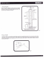
If the stove is to be installed on a combustible floor, it must be placed on an approved l/2" (13mm) non-combustible hearth
pad with k = 0.84 BTU/in ft2 hr'F. In the USA, the floor protecior must extend 8" beyond each side of the flue loading door
and 16" to the front. In Canada, the floor protector must extend 8" (200mm) beyond each side and the back of the appliance
and 18" (450mm) to the front. (See fig. 1)
16"-USA
18" (450mm) Canada
Fig.
1
. a rear vent installation the floor protection must also extend under the stovepipe a minimum of 2" (50mm) beyond either
side of the pipe.
How to determine if alternate floor protection materials are acceptable.
All floor protection must be non-combustible (i.e., metals, brick, stone, mineral fiber boards, etc.). Any organic-materials-(i.e.,
plastics, riirood paper products, etc) gre combustible and must not be used. The floor protection specified includes some form
bf thermal desigriatioh such as R-value (thermal resistance) or k-factor (thermal conductivity).
Procedure:
1. Convert specification to R-value:
i. R-value given -
no conversion needed.
ii. k-factor is given
with
a required thickness (T) in inches: n
a required thickness (T) in inches:n
iii. K-factor is given
with
iv. r-factor is given
with a required thickness
(T)
=f
x
f
=1fu
x
f
in inches: R = r x T
2. Determine the R-value of the proposed alternate floor protector.
i. Use the formula in step (1) to convert values not expressed as "R".
ii.
For multiple layers, add R-values of each layer to determine overall R-value.
If the overall R-value of the system is greater than the R-value of the specified floor protector, the alternate is acceptable.
Example: The specified floor protector should be 3/4-inch thick material with a k-factor of 0.84. The proposed alternate
4" bricit with an i-factor of 0.2 over 1/8" mineral board with a k-factor of 0.29.
is
Step (a): Use formula above to convert specification to R-value.
R= *"
t =*nx
0.75 = 0.8e3
Step (b): Calculate R of proposed system.
4" brick of r = 0.2, therefore:
-
Rbrick=0.2x4=0.431
1/8" mineral board of k = 0.29, therefore
Rmineralboard
0.125 = 0.431
=
"tnx
Rtotal = Rbrick+ Rmineralboard= 0.8 + 0.431
Step (c): Compare proposed system
the system is acceptable.
Rtotal
=
of 1.231 to specified
l'23I
R
of 0.893. Since proposed system Rtotal is greater than required,
Definitions
-K=
(ftz) (hr) ("F)
Btu
k=
(Ptu) (in)
(ftz) (hr) ('F)
= Kx
12
..
t\=
(Btu) (ft)
(ftz) (hr) ("F)
r
_ (ftl (hr) ("F)
(Btu) (in)
_1
k
Installation Clearances
It is extremely important that you respect required installation distances and that you respect local installation regulations.
This is for yorir safbty! The manufacturer is not iesponsible for the product, if it is not iristalled following these recommendations.
These clearances may only be reduced by means approved by the regulatory authority.
A combustible surface is anything that can burn (i.e. sheet rock, wallpaper, wood, fabrics etc.) These surfaces are not limited
to those that are visible anil also include materials that are behind non-combustible materials. If you are not sure of the
combustible nature of a material, consult your local fire o{Iicials.
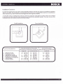
Parallel Installation
CLEARANCE REQUIREMENTS:
A.. SIDEWALL TO UNIT
B.- BACKWALTTO UNIT
C. CORNERWATLTO UNIT
D.- SIDEWALL TO CONNECTOR
E.. BACKWALLTOCONNECTOR
F. CORNERWALLTOCONNECTOR
G.- UNIT TO CEILING
H.- FLOORTO CEILING
Corner Installation
STANDARD RESIDENTIAT INSTATLATION
(SINGLEWAII & DOUBTEWALL CONNECTOR):
11.5" (292mm)
15"
19"
(381mm)
N/A
(483 mm)
17.5' (444 mm)
55"
84'
N/A
(1.397 mm)
(2.134 mm)
(292 mm)
(304 mm)
(152 mm)
6"
18.5', (470 mm)
r4" (356 mm)
t4 (356 mm)
55" (1.397 mm)
a4^ (2.134 mm)
l 1.5"
1z'*
ALCOVE INSTATTATION
WITH (DOUBIE WALL CONNECTOR):
11.5"
(292 mm)
(305 mm)
18.5"
14"
(470 mm)
(356 mm)
55"
84"
(1.397 mm)
(2.134 mm)
12'
N/A
N/A
'himney Connection
The chimney connector is a single walled pipe used to connect the stove to the chimney. For use with the appliance the
chimney connector MUST be 6" in diameter, with a minimum thickness of 24 gauge black steel or 26 gauge blued steel.
Aluminium and galvanized steel pipe is not acceptable for use with the appliance. These materials cannot withstand the
extreme temperatures of a wood fire and can give off toxic fumes when heated.
Do not use the connector pipe
as a chimney.
Each chimney connector or stovepipe section must be installed to the stove flue collar and to each other with the male
(crimped) end toward the stove. See fig 2.
,,J-,ffi,,"1"^,
"i'no*Too'
Fig.2
This prevents any amount of condensed or liquid creosote from running down the outside of the pipe or the stovetop. All
joints, including the flue collar connection must be secured with three sheet metal screws to ensure that the sections do not
separate.
For the best performance the chimney connector should be as short and direct as possible, with no more than two 90 elbows.
The maximum horizontal run is 36" and a recommended total length of stovepipe should not exceed 10 feet. Always slope
horizontal runs upward l+" per foot toward the chimney.
No part of the chimney connector may pass through an attic or roof space, closet or other concealed space, or through a
floor ceiling. All sections of the chimney connectors must be accessible for cleaning. Where passage through a wall or parti'tion
of combustible construction is desired, the installation must conform with NFPA 2Il or CAN/CSA-8365, and is also addressed
in this manual.
CHIMNEY
DO NOT CONNECT THIS UNIT TO A CHIMNEY
FLUE SERVING ANOTHER APPLIANCE. DO NOT
CONNECT TO ANY AIR DISTRIBUTION DUCT OR
SYSTEM.
{his room heater must be connected to a 6" factory built UL 103 HT chimney (ULC 5629, in Canada) or a code-approved
asonry chimney with a flue liner.
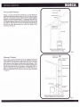
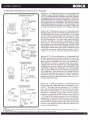
Factory Built Chimney
When a metal prefabricated chimney is used, BOSCA's
installation inshuctions must be followed. You must also purchase
(from an authorized retailer) and install the ceiling support
package or wall pass{hrough and'T" section package, firestops
(where needed), insulation shield, roof flashing, chimney cap,
etc. Maintain proper clearance to the strucflrre as recommended
bv BOSCA. The-chimne.y must be the required height above
tlie roof or other obstrlctions for safety and proper draft
operation. (See fig.3)
Sunoort Box
widh'built - in
starter section
One storv house installation with atlic
Chimriey is supported by celling
Fig.3
Masonry Chimney
Adjustable roof
Ensure that a masonry chimne.y meets the minimum standards
of the National Fire Piotection Association (NFPA) by having it
inspected by a professional. Make sure there are no cracks,
loose mortaror other signs of deterioration and blockage. Have
the chimney cleaned before the stove is installed and operated.
When conirecting the stove through a combustible wallto a
masonry chimnei, special methods are needed (See fig. 4).
Refer to-Combustible Wa-ll Chimney Connector Pass-Throughs
Flashing
Chimney Sections
Chase Enclosure
on page 9.
Wall Strap
WallThimble
Tee Support
Bracket
Tee Clean - Oul
Access Door
Chimney through outer wall with enclosed chase
Chimney is supported by tee support bracket
Iasonry Fireplace
There are listed kits available to connect a stove to a masonry
fireplace. The kit is an adapter that is installed at the location of
the'fireplace damper. Th'e existing damper may have to be
removed to allow installation. (See fig. 5)
Chimnev throueh ouler wall wilh enclosed chase
Chimirey is sripported by tee suppon bracket
Fig.5
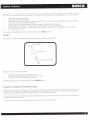
Chimney Height
A masonrv chimnev or a listed factory-build chimney must be the required height above the roof and any other nearby
p-oint wherg it pass^es through the roof and
;;;iil t;;t.'ift" .'trt"ir*v -rti U" ,i teast 3; (90 cni) higher than the'highest
10' (305 crir; of the chimney, measured
within
thalis
iootor
structure
the
;il";;ii;i6-0 ;i h[h;;l'hi" tn" nign"sipart'of
horizontally
(See
fig. 6).
Combustible Wall Chimney Connector Pass - Throughs
Minimum chimenev cleaance lo brick
and combustibles Z in. (50.8 mm)
Method 4.I2" (304.8 mm) Clearance to Combustible Wall
Member: Using a minimum thickness 3.5" (89 mm) brick and
a 5/8" (15.9 mm) minimum wall thickness clay liner, construct
a wall pass{hrough. The clay liner must conform to ASTM C31 5
(Standard Specification for Clay Fire linings) or its equivalent.
I(eep a minimum of 12" (304.8 mm) of brick masonry between
the clay liner and wall combustibles. The clay liner shall run
from the brick masonry outer surface to the inner surface of the
chimney flue liner buinot past the inner surface. Firmly grout
or cement the clay liner in place to the chimney flue liner.
rllll
tffi]
ffiEt
Tlffill
I lF:*r#
U-rT
E
O
ll
--11
Method 8.9" (228.6 mm) Clearance to Combustible Wall
Minimum 12 in. (304.8 mm)
to comhrrsiibles
Minimum clearance
9 in. (228.6 mm)
Chimnev
Conneclor
Use chimnev
mfrs. Darts td
Member: Using a 6" (L52.4 mm) inside diameter,listed, factorybuilt Solid-Pak chimney section with insulation of 1" (25.4 mm)
or more, build a wallpass-through with a minimum 9" (228.6
mm) air space between the outer wall of the chimney length
and wall combustibles. Use sheet metal supports fastened
securely to wallsurfaces on all sides, to maintain the 9" (228.6
mm) air space. When fastening supports to chimney length,
do not penehate the chimney liner (the inside wall of the SolidPak chimney). The inner end of the Solid-Pak chimney section
shallbe flush with the inside of the masonry chimney flue, and
sealed with a non-water soluble refractory cement. Use this
cement to also seal to the brick masonry penetration.
attach connector
securely
U
{-*
F7l' \ Solid-insulated
fn
Ulsted factorv buill
llqsoroy \ \ chimneylehght
Uhimney
Sheet steel
supports
Minimum chrmeney clearance to
sheet steel suDborts and
combustibles 2 in (50.8 mm)
Two air channels
each lin. (25.4mm)
Chimney
conneal6r
Minimum 6 in.
(152.4 mm)
fiber insuhtion
glass
Masonrv
Chimney
Method C. 6" (152.4 mm) Clearance to Combustible Wall
Member: Starting with a minimum 24 gage (.02a" [.61 mml)
6" (152.4 mm) metal chimney connector, and a minimum24
gage ventilated wall thimble which has two air channels of 1"
(25.4 mm) each, construct a wall pass-through. There shall be
a minimum 6" (152.4) mm separation area containing fiberglass
insulation, from the outer surface of the wall thimble to wall
combustibles. Support the wall thimble, and cover its opening
with a Z$-gage minimum sheet metal support. Maintain the 6'
(152.4 mm) space. There should also be a support sized to fit
and hold the metal chimney connector. See that the supports
are fastened securely to wall surfaces on all sides. Make sure
fasteners used to secure the metal chimney connector do not
penetrate chimney flue liner.
iheet steel
supports
Method D. 2" (50.8 mm) Clearance to Combustible Wall
Minimum chimenev clearance to
sheet steel suDborts and
combustibles 2 iri. (50.8 mm)
Minimum clearance
1 in. (25.4 mm)
Masonrv
Chimne'y
Member: Start with a solid-paklisted factory built chimney section
at least 12" (3O4 mm) long, with insulation of 1" (25.4 mm) or
more, and an inside diameter of 8" (2 inches [51 mm] larger
than the 6" 1152.4 mml chimney connector). Use this as a passthrough for a minimum Z\-gage single wall steel chimney
connector. Keep solid-pak section concentric with and spaced
1" (25.4 mm) offthe chimney connector by way of sheet metal
support plates at both ends of chimney section. Cover opening
with and support chimney section on both sides with 24 gage
minimum sheet metal supports. See that the supports are fastened
securely to wall surfaces on all sides. Make sure fasteners used
to secure chimney flue liner.
NOTES:
1. Connectors to a masonry chimney, excepting method B, shall extend in one continuous section through the wall pas{hrough system and the chimney wall, to but not past
the inner flue liner face.
2. A chimnev connector shall not
an attic or roof space, closet or similar concealed space. or a floor. or
MOBILE HOME INSTALLATION
Follow these special requirements for installing your stove in a
mobile home:
-
An outside air inlet must be provided for combustion and must
remain clear of leaves, debiis ice and/or snow. It must be
unrestricted while unit is in use to prevent room air starvation
which can cause smoke spillage andbn inability to maintain a fire.
Smoke spillage can also set off smoke alarms.
- Outside air inlet installation: Use a BOSCA connector (see
Reolacement Parts. ps. l6) which you can purchase from an
ofdcial BOSCA deaiel a 4" single invall aluminum flex pipe of
appropriate length for installation, a rain cap and two 4" clamps,
avaita6te at youilocal hardware retailer'
To install the outside air inlet, place the connector over through
the hole behind the heater, connect the flex pipe and altach it
securelv with one of the two clamps. The other side of the flex
pipe sfiould be connected on the outside to the rain cap'
-
Permanentlv attach the stove to your mobile home's floor. The
-urib" bolted to the flodr. Use /+" holes in the base to
bolt down the stove.
pedestal
-
Regulation requires that unit-must be grounded. Attach a piece
of #f,8 cooper wire, at least 18" in length from the stove to the
'hassis of the mobile home.
- Stove must be installed with an approved Ut103 HT ventilated
chimnev connector, Ut103 HT chimney and terminal cap with
spark airestor. Never use a single wall'connector in a mobile
home installation.
- See clearances to combustibles on page 5 of this Manual or in
the Serial Number Label on the back of the stove.
- Follow the floor protections requirements detailed o n page 3.
-
In Canada, this stove must be connected to a 6" factory-built
chimney conforming to CAN/ULC-629M.
-
Use slicone to create an effective vapor barrier at the location
where the chimney or other componenfs penetrates to the exterior
of the structure.
- Follow the chimney and chimney connector manufacturer's
instructions when installing the flu-e system for use in mobile
homes.
-
Burn wood only. Other fuels may generate poisonous gases.
Chimney must be removed when transporting mobile home.
CAUTION:
WARNING:
DO NOT INSTALL IN SLEEPING ROOM
THE STRUCTURAL INTEGRITY OF THE MOBILE
HOME FLOOR, WALL AND CEILING/ROOF MUST
BE MAINTAINED.
OPERATING AND LIGHTING INSTRUCTIONS
your GOLD 400's performance depends largely on how it
is
operated. Please read this section carefully before lighting your
first fire.
When vou lisht vour first fire, the stove will emit some smoke and the smell
vent th6
rooir attd eliminate the
smell
of
paint. This is normal. Open the windows to
.
Before lighting your stove, ensure that the baffle is correctly installed. For baffle installation instructions, see page 12
(Maintenance).
Before lighting your stove, ensure that the refractory bricks are correctly installed. For refractory bricks installation instructions,
see page 14 fMaintenance).
Lighting
I
t
t
!
I
I
t
!"
Place crushed sheets of paper or firelighters in the center of the firebox.
place some kindling on top of the paper and some small split logs, preferably in a vertical position.
Light the fire and close the door.
Open the door of the ashtray and leave it this way for approximately 3 minutes or until the split logs are alight.
Add the load of firewood, placing the lightest logs directly over the fire and the heavier ones on top of these.
Close the door of the firebox and maintain the door of the ashtray open for approximately 5 more minrrtes.
Once the logs are alight, close the door and place the Air Control on HIGH for 20 minutes.
When the stove reaches the operation temperatqle atq there is sufficient draft, graduate the Air Control to the
deslied position. lt is recommefidable to slowly adjust this command before graduating to the MEDIUM position
(prolonged combustion)'
you will find bv experience how to best manage your slove to your liking. You must not expect an immediate reaction
il; iilffi r.,Jn"ti1noui"g the Air Control. fhE flame willnot intensify n6r extinguish quickly as it would with liquid
or gas fuels. Solid fuels, like fnewood, react slowly'
lf the fire is initiated as instructed, a good base is established for an effective combustion that is smokeless and that
does not pollute.
WARNING
DO NOT OVERFIRE.IF THE STOVETOP OR
CHIMNEY CONNECTORPIPE GLOW RED,
YOU ARE OVERFIRING.
IMPORTANT
DO NOT OPERATE THE STOVE FOR
PROLONGED PERIODS WITH THE DOOR OF
THE ASHTRAY OPEN. DO SO ONLY UNTIL THE
WOOD LOAD IS ALIGHT.
Reloading
!
!
I
I
u
Place the Air Controlin the HIGH position.
Place the dry firewood on top of the live coals remaining'
Open the door of the ashtray for 5 minutes or until the load alights.
Never load the firewood when the flames are vigorous.
Graduate the Air Conhol to HIGH for a few minutes. Once the stove
place the Air Controlin the desired position.
is
maintaining stable combustion,
To obtain good combustion during the whole night, proceed as follows:
!
U
I
Form a base of live coals at the bottom of the firebox.
load the stove completely with dry firewood.
When flames begin to appi:ar on the logs move the Air Control to MEDIUM.
How do I load my stove after a prolonged combustion?
I
_[
!
U
At the end of a long combustion cycle, reestablish the fire adding a few small split logs and small
logs.
.pen the door of the ashtray for 5 minutes or until the split logs and small logs are alight.
o_f tlre stove to recuperat-e belore adding i-arger ldgs.
Reload the stove according to the description above.
O.
{llow- the temperature
MAINTENANCE
The Gold 400 requires little maintenance. However, there are parts of your stove that should be checked periodically.
Baffle
Your Gold 400 stove has a removeable baffle that needs to be replaced periodically, depending on the stove's use.
When the baffle needs to be removed, make sure that the stove i^s cold liefore putiing your ha"nds into the firebox.
To replace the baffle, you have to dismantle the rear panel of your stove (fig.7):
1)
\
Release the 4 bolts located on the sides of the rear panel, using a 10mm wrench.
Remove the rear panel, pulling it towards you.
3)
Remove the air pipe protector, sliding it upwards.
4)
Release the bolts that fix the baffle to the firebox, using a 10mm wrench.
5)
Once the bolts are loose, slide the baflle down as indicated in figure 8. Carefull.y, angle the baffle on one side
to make sure it doesn't accidentally fall, as this may result in serioirs injury (fig. 9f
6)
To place the new baffle in its proper position, insert it into the firebox,
in such a way that it rests on the support brackets installed specially for
the baffle. Make sure that the baffle air pipe is inserted completely-into
the hole in the back of the firebox (Fig 10) and the bolts have gone
through the holes to the outside of the-hxebox.
7)
Bolt the baffle to the rear wall of the firebox from the outside.
8)
Place the air pipe protector back in its normal position.
e)
Place the rear panel back in place, be sure that it is correctly set and
bolt it.
Fig. 10
Disposal of Ashes
your unit's fuebox has a qrooved base, through which the ashes from the wood burned automatically deposit intg th9 ashbin'
Wn"" the ashbin is full,"make sure that the s'iove and the ashes are cold (remember that the coals can remain hot tor up to
placed
S6 ho"iii and place the iihes in a metal container with a tight fitting lid. The closed container of ashes should be
ashes
If
the
disposal.
materials,.pending.final
coribustible
froir
all
away
ground,
well
." " "r*"*n[rtinr" nooi - on rhe
;;;;irp;il oi uy nrriai in soil or othe?wise locally dispeised they should be retained in the close-d container until all cinders
have thoroughly cooled.
NOTE: To open the ashbin door, you have to use the steel handle provided with your stove.
Glass Replacements
The front glass is a ceramic glass, especially made for use in wood stoves, and should therefore not be marred by normal
use of the stove.
If for any reason the glass does break, it will be necessary to replace
it.
Never operate your stove with broken glass'
Fig. 7
Replace the glass as follows:
-
Make sure that the fire is completely extinguished and the stove is cold.
Protect your hands with gloves thai are appropriate for this type of work.
Removti the front door, c-arefully pushing it upward (fig 7).
Place the door on a flat surface.
Unscrew the bolts that hold down the stainless-steel frame on the stove door.
i;fi;; th" aroi t*-" fto- the glass. The g.lass^should be loose on the door, once the frame has been removed'
pla'ce a new sfrllt of gtass on the door, resetThe frame in its original position, then screw the frame in place on the
door.
Reinstall the door, inserting the bottom part first, then the top part'
Before lighting a new fire, ensure that the door is seated in its conect position.
use only ceramic glass for use in wood stoves. Do not use other type of glass.
If the ceramic glass of your stove needs to be replaced, contact your Oflicial BOSCA Dealer.
Glass Cleaning
One of the more attractive features of your stove is that you can actually enjoy seeing the fire. However, your view may be
obscured when the glass becomes dirty.
In order to minimize this, we recommend the following advice:
-
The main cause of dirt spots on your glass is directly connected with the humidity^ content of the wood used, along
with maintaining the Aii Controi settiilg on "Low" Fosition. Use only dry wood. Store it adequately, and keep the
Air Control at the "Medium" position.
Clean the glass periodically ririttr a commercial stove glass cleaner, waiting until the glass is completely cold before
cleaning.
)oors Gasket Replacement
STAINLESS STEET FRAME
Your GOLD 400 uses rope{ype fiberglass gaskets at the interior of the front and ashtray doors to sealed it. After a time of
use, gaskets can become brittle and compressed, begin to lose their effectiveness and need to be replace.
To replace any gasket, be sure that the fire is out and the stove is cold and follow as is describe:
*
Use Fil-Tec
MD .500 G Black Fiberglass Rope or equivalent.
Remove the existing gasket.
Clean the stainless steel channel.
Measure the length of the rope by laying it out in the stainless steel channel.
Remove the rope from the channel and cut it to the appropriate length. Take care to ensure that the rope does not
unravel.
Place a bead of high-temperature adhesive in the clean stainless-steelchannel.
Beginning at one of the ends, press the gasket into the stainless-steel channel interior.
Before cutting, make sure the rope ends properly meet. Do not overlap rope ends.
Firmly press the rope en make sure it properly seats into the stainless-steel channel interior.
Clean any excess adhesive and allow to dry.
Refractory Bricks Installing and Replacement
Your GOID 400's firebox interior is covered with 16 refractory bricks (figure 13 a.). To avoid damages in your stove during
the transport, the refractory bricks are not installed and are st<ired in a'b"ox inside your stove firebox]
To install the refractory bricks, proceed as follow:
-
Use gloves to protect your hands
Install the refractory bricks as shown in figure 13 b.
-.b
,{
-,:t'
',,.,?
cr;n
fig.13
a.
-2
fig. 13 b.
Some bricks may brake due
ritniioicuis,
if
to the normai use of the appliance or from impact when loading wood.
proc'eea as follows. after making sure that any fire is extinguished and the appliance and brick are cold
Use gloves to Protecl Your hands
Clean anY ashes from the flrebox
js
boftom
Take hold of the brick to be replaced, and push it upwards. Th should leave you enough space to move the
of the brrck toward the center of the frrebox
Clean any pieces of brick remaining rn the space where lhe new brick wtll be-placed
To insert the new brick. place the upper end in the molding in the top part ol the flrebox
Cnce the uppJr p-rt oi in" brick is well seated, push it toilards the tnside surface of lhe firebox, until the brick ts
completely seated in Place
you need to replace Refractory
Bricks, check with
your Cffrcjal BOSCA Dealer
Handle
After some use, it may be necessary to replace the wood part of the front door handle
,
\5
STEFL HANDLE
fu
wooD
HANDLE
\uVn
T HLAD
cuP
sCRr
w
,,r,so'^l
\x
u
Replace the wooden handle as follows:
-
Be sure that the fire is out and the stove is cold
Remove the existing wood handie {use a N"4 Allan keyJ
Turn the screw as far as possible and remove
To replace the wood handle, check with your Official BOSCA Deaier
Creosote - Formation and need for removal
When wood js burned slowly. it produces tar and other organic vapors, which combine with expelled moisture to form
c[eosote The c[eosote uJpors'ion'aense in the relatively cool dhrmney flue of a slow burntng fire. As a resull creosote re-sidue
accumulates on the flue linrng. When ignited this creosole makes an extremely hot fire.
The chimney connector and chimney should be inspected at least every n^io months during the heatjng season to delermine
if creosole build up has occurred
lf creosote has accumulated it should be removed to reduce the risk of a chimney fire.
-now
Your GOLD 400 will operate with few problems, and most of those willoccur due to inconect operation, poor-quality wood,
improper installation, or failure to clean the flue piping.
The following lists solutions to the most common problems in the operation of the Gold 400:
-Reload.your stove when it has a good bed of embers
Set the"Air Control in "Mddium" o"r "Hish" oosition.
-Use seasoned wood
lt is normal for your stove to emit smoke during the first
few minutes of operation. The smoke will disip"ate when
the firebox reaches the normal operating temperature..
-
- Use seasoned wood
- I(eep the Air Controlat "Medium" or "High" position
- Make sure that the gasket is in good conclition.
- If
your heater
is
more than 2 years old, replace the baffle."
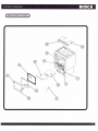
REPLACEMENT PARTS
N"
Code
Description
I
r2720055
Door (without ceramic glass)
2
10320008
Ceramic Glass (with gasket)
3
r0310290
Refractory Bricks (set)
4
10320095
Ashpan
5
12720056
Wood Handle Assembly
6
10320027
Baffle
7
10310320
Outside Air Connector
8
t2720058
Grate
I
12720059
Grate Plate
10
12720060
Ashlip
11
t272006r
Ash Door Rope
t2
103201 55
Ash Door Latch
13
t2720073
Ash Door Handle
T4
103 102
1
r
Glass Retainer (with brackets, screws and rope)
l5
302301
1
l
Owner's Manual
f RnprncEMENT pnnrs )
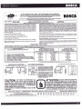
o**qffi",,,r*
o
DO NOT REMOVE THIS LABEL / NE PAS ENLEVER CETTE ETIQUETTE
RESTRICTIONS IN YOURAREA. / REINSEIGNEZCONTACT
-vous LOCAL BUILDING OR FIRE OFFICIALS ABOUT INSTALLATION AND
oE LA coNsrRUcTroN ET DE LA PREVENT|oN DEs lNcENDlEs Au sUJET DEs
euFnes oEs Auionnrs
RESTRICTIONS ET INSPECTIONS D1NSTALLATION DANS VOTRE REGION.
r-ocllrs
LISTEO SOLID FUEL BURNING APPLIANCE SUITABLE FOR USE IN RESIDENTIAL INSTALLATIONS. / APPAREIL DE CHAUFFAGE
A
BOgCfi
coMBusrtsLes Softoes HoMoLoGuE PouR lNsrALLATloNs RESIDENTIELLES.
TESTED T0 / TESTE AUX NORMES: UL '1482, ULC'S627
Room Heater, Solid Fuel Type. Also for use in mobile homes.
de Chauflaqe i Cbmbustibles Solides. Pour usage dans les maisons mobiles'
uooeuuooEu, GOLD 400
pneVgtlf
XOUSE FIRES - lnstall and use only in accordence with the manufaclurer's
installation and operating instructions. Contact your local building or fire officials
about restrictions and inltallation inspection in your area. Refer to local building
iodes and manufacturer's instructidns for precautions required for passing a
chimnev trouoh a combustible wall ceiling. Do not run a chimney connector
trouoh
comSustible wall ceilinq' Do notionnect this unit to a chimney flue
servinq another appliance. Clearances may be reduced by methods sp€cified in
NFPA
listed w-all shields, pipe shields, or other means approved by local
i
ill,
building or fire officials.
Do not use a grate to elevate
fire'
;;;i;;ii;;
bpprouv6s par les autoiit6s de
la construction et de la p16vention des Incendles.
Ne pas utiliser une grille suppl6mentaire pour 6lever le feu - faites le feu directement sur le foyer.
build fire directly on hearth.
Ne pas faire fonctonnier l'aappareil avec la porte cendrier ouverle.
i
Do not operate with the ash door open'
lf
luiei
Faites fonctionner l'appareil avec les portes de chargement ferm6es - ouvrir uniquement pour charger.
with feed door closed - open to feed fire only.
DO NOT OVERFIRE -
PREVENTION DES INCENDIES: lnstallez et utilisez conform6ment aux instructions du fabricant.
la pr6vention des incendies au
d6 restrictions'et insDections d'installation dans votre 169ion, Des m6thodes sp6ciales sont
re6uises lors du percaoe d'un mur ou plafond. Vdrifier les instructions du fabricant et les codes du
balimeiri.'[fpas Iaii6-p'aliei te tuvau de chemmin6e directament d travers une surface combustible.
Hlpil irjni'6ctiiietiirplreii a id chemin6e d un autre.alpareil. Les d6sasements minimaux des
i"it'eiiiiilorir-U'ristittlJiiuvent etie ia;ilii;aelo;; le; ;eili5des tpdcifi0e5 dins NFPA 211. avec des
ilffiGJhorfiotoqudes. oes protections de chimen6e hbmologu6es, ou d'autres moy€ns
itl""Liii.r'el-.viroiJupiaJaJsiutoiitas tocales de la construction et de
Pour usage uniquement avec du bois,
For use with solid wood fuel only (cord wood).
Operated
Serial Number
Numero de Serie
heater or chimney connectors glows, you are overfiring.
lnspect and clean chimney frequently ' under certain condictions of use, creosote
buildup may occur rapidly.
NE pAS SURCHAUFFER - Si une partie de I'appareil ou du reccordement de chemin6e commence
rougeoyer, vous etes en situation ile surchauffe.
lnspecter 6t nettoyer la chemin6e frdquentmment; dans certaines conditions de fonctionnemment (par
exdmple, mise ai ralenti sans attendre la combustions des volatiles) une formation de cr6osote
goudron puet se produire rapidement.
FREESTANDING / INSTALLATION
for use with solid fuels or masonry chimney. / pour les lnstallatlons resloenuelEs:
Msc
rrna chemin6e or6fabrioi6e homoioqu6e (tvpe UL103 HT ou ULC 5629) ou
'crs
rrs une chemin6e maconn6e,
STANDARD RESIDENTIAL INSTALLATION
(SINGLEWALL & DOUBLEWALL CONNECTOR):
'
INSTALLATION RESIDENTIELLE STANDARD
{TUYAU DE RACCORDEMENT A SIMPLE PAROI ET A DOUBLE PAROD:
CLEARANCE REQUIREMENTS;
D€GAGEMENTS MtN|MAUx 0Es MATERIAUX c0MBUsrlBLEs:
8..
c.D..
E.F..
G..
H.-
S|DEWALL TO UNlr / DU MUR DE COTE AU POELE
BACKWALL TO UNIT / DU MUR ARRIERE AU POELF
CORNERWALL TO UNIT / DU MUR DU COIN AU POELE
SIDEWALL TO CONNECTOR / DU MUR DE COTE AU RECCORD DE CHEMINEE
ahqifuLL io-c-oprecroi iDU MUR ARRIERE AU REccoRD DE cHEMINEE,
coriHinwarr TO CONNECTOR i DU MUR DE COIN AU RECCORO DE CHEMINEI
UNIT TO CEILING / DU POELE AU PLAFOND
FLOOR TO CEILING / DU SOL AU PLAFOND
MINIMUM CLEARANCES TO
N/A
18.5" (470 mm)
14" {356 mm)
N/A
55" (1397 mm)
84" (2134 mm)
FRONTISIDES/REAR
OTHER COMBUSTIBLE MATERIALS
A
INDICATED.
S.A.
Americo Vespucio Norte 2077 - Huechuraba
U.S. ENVIROMENTAL PROTECTION AGENCY
certified to comply with July 1990 particulate emission standards:
Certifi6 conforme aux normds'EPA de jdlliet 1900 puor les 6missions de particules solides
-E
+b
ao
:P
io
6e
6=
9x
=.'
a=
=o
;B
0
N
?i,' Y.l'J,?'lll;
: ft
ENTI
ER,: ff E
CONTACT PEU CAUSER DES BRULURES A LA PEAU. GARDEZ
LES ENFANTS, LES VETEMENTS, LES MEUBLES, ET TOUS LES
MATERIAUX COMBUSTIBLES LOIN DE L'ESPACE DESIGNE DE
L'APPAREIL. LIRE ATTENTIVEMENT LES ETIQUETTES ET LES
INSTRUCTIoNS, NE PAS SURCHAUFFER. Sl L'APPAREIL 0U LE
TUYAU DE CHEMINEE ROUGISSENT, VOUS SURCHAUFFEZ,
CONSIDERABLE
BO$CA CHILE
BACK WALL / MUR ARRIERE
ATT
DISTANCE AWAY FROM THE APPLIANCE.
DO NOT OVERFIRE.IF HEATER OR CHIMNEY GLOWS, YOU ARE
OVERFIRING.
par:
AS
LE PROTECTEUR DE PLANCI{ER DOIT ETRE
D.UNE EPAISSEUR MINIMUM DE %", D.UN
MAT€RIAL INCOMBUSTIBLE AVANT UNE
VALEUR DiSOLATION DE Kx.84. IL DOIT
s'ETENDRE EN DESSOUS DE L.APPAREN ET
ru oevanr lux coTEs ET A L ARRTERE DE
L'APPAREII. COMME INIDIQUE.
: il31 #ilt',: l[,?%'frfJl?il
Manufactured By: / Fabriqu6
ALCOVE INSTALLATION / INSTATLATION ALCOVE
FLOOR PROTECTOR MUST BE A %" MINIMUM
THICKNESS, NON.COMBUSTIBLE MATERIAL
HAVING AN EQUAL OR BETTER INSULATING
VALUE (LOWER K VALUE) OF kx.84. lT MUST
EXTEND BENEATH HEATER. AND TO THE
SEE
CLOTHING AWAY. CONTACT MAY CAUSE SKIN BURNS. ^RB
NAMEPLATE AND INSTRUCTIONS, KEEP FURNISHINGS AND
\-/
'12" (305 mm)
NoN - COMBUSTIBLE FLOOR PROTECTOR
COMBUSTIBLES: PROTECTEUR DE PLANcHER INCoMBUSTIBLE
*E@-qEE
N
(292 mm)
(304 mm)
(152 mm)
(470 mm)
(356 mm)
(356 mm)
55" (1397 mm)
84" {2134 mm)
COMBUSTIBLES:
lUx umennUX
BAcKWALL / MUR ARRIERE ADJACENT WALL / MUR ADJACENT
CAUTI 0
11.5" (292 mm)
'11.5"
12"
6"
18.5"
14"
14"
11.5" (292 mm)
15" (381 mm)
N/A
19" (483 mm)
17.5" (444mm)
N/A
55" (1397mm)
(2134mm)
84"
Pour d'autres modes d installation et degagoments suppl€montaires consultez votrgs manuel du proprietairo.
For additional types of installations and clearances consult your owners manual
DEGAGEMENia'Mt-tXlrteux
Doublewall
Corner Doublewall
Sinqlewall
A..
ALCOVE INSTALLATION
WITH {DOUBLE WALL CONNECTOR):
INSTALLATION DANS UN ALCOVE
IUYAU DE RACCORDEMENTAU DOUBLE PAROI)
'
Santiago
' Chile
ifi
MADE IN CHILE / FABRIQUE AU CHILI
nnnt]nn ntr nn!trntrnv
2006 2007 2008
Jan. Feb.
Mar
Apr.
May
June July Aug. Sep, Oct. Nov. Dec.
fi
LIFETIME LIMITED WARRANTY
Statement of Policy:
BOSCA warrants its products from component failure and defects in material or workmanship per the terms of the warranty
supplied with the product. All dealers and distributors shall honor BOSCA's wananties, regardless of whether they sold and
installed the product or not.
Installation and startup procedures are considered to be normal required activities not associated with warranty service. Issues
such as air shutter adjustments or venting should be included in startup. Such procedures are nor covered by warranty.
Warranty Period:
The warranty period for consumers begins at date of occupancy (new construction) or date of installation (remodel).
Limited Lifetime Warranty:
BOSCA's limited lifetime wananty guarantees that the following components will work as designed for the first 5 years on
all Wood Stoves to the original purchaser. This warranty covers: firebox, firebox panels, panels and door assembly. Certain
restrictions and exclusion may apply.
One Year Warranty:
Under this warranty, BOSCA covers all exterior surface finishes against defects in material and workmanship, for part repair
or replacements and limited for the first year to the original purchaser. Certain restriction and exclusions may apply.
CONDITIONS
This warranty is non-transferable and is made to the original retail purchaser only provided that the purchase was made
through an authorized dealer of BOSCA. It must be installed and operated at all times in accordance with the Installation
and Operating Instructions furnished with the product, as well as any applicable local and national codes. Any alteration,
willful abuse, accident, or misuse of the product shall nullify this wananty. This limited Lifetime Wananty does not extend to
or included surface finish on the appliance, door gasketing, glass gasketing, glass, firebricks. It does not cover installation or
operational-related problems such as overfiring, use of corrosive driftwood, downdrafts or spillage caused by environmental
conditions, nearby trees, buildings, hilttops, mountains, inadequate venting or ventilation, excessive offsets, or negative air
pressures caused by mechanicals systems such as fumaces, fans, clothes dryers, etc. Any installation, construction, transportation,
or other related costs or expenses arising from defective part(s), repair, replacement, etc., will not be covered by this warranty,
nor will BOSCA assume responsibility for them. Further, BOSCA will not be responsible for any incidental, indirect, or
consequential damages, except as results in damage to the interior or exterior of the building in which this appliance is
installed. This limited Lifetime Wananty does not apply to the venting components, hearth components or other accessories
used in conjunction with the installation of this product not manufactured by BOSCA.
This wananty is void if the stove has been over fired or operated in atmospheres contaminated by chlorine, fluorine, or other
damaging chemicals, the stove is subjected to prolonged periods of dampness or condensation, or there is any damage to
the stolebr other components due to water or weather damage which is the result ol but not limited to, improper chimney
or venting installation. BOSCA may, at its discretion, fully discharge all obligations with respect to this warranty by either
repairing br replacing the unit, or refunding the wholesale price of the defective part(s).
The wananty extended by BOSCA described above covers only the stoves appliances sold in the United States and Canada,
and will be considered null or avoid if the Serial Label is removed or altered.
The Dealer is not authorized to alter this wananty.
Wananty limitations may not apply
- - - in your area. This warranty gives you specific legal rights. You may also have other rights
which viry from state to state.
All other stove warranties, expressed or implied are excluded to the extent possible by law. In addition, consumers also may
have other rights under relevant State and Commonwealth [aws.
LIFETIME LIMITED WARRANTY
IMPORTANT INFORMATION
Model:
Style:
Serial Number:
Purchase Date:
Purchased From:
BOSCA CHITE S.A.
Av. Am6rico Vespucio 2077
Huechuraba
Santiago - Chile
Telephone: (56) 2 3288500
Fax: (56) 2 624 t89'
-
Made in Chile
www.boscastoves.com