1
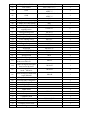
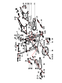
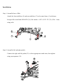
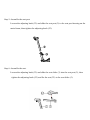
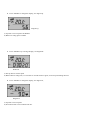
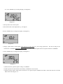
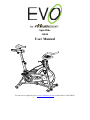
Spin Bike
300SB
User Manual
For all service enquiries go to www.evofitness.net.au or call toll free 1300796636
CONTENTS
SAFETY & MAINTENANCE INSTRUCTIONS……………….…….…….1
GENERAL KNOWLEDGE …………....………...……..………..…………..2
ASSEMBLY INSTRUCTIONS……..……………………….…….………….3-12
SAFETY & MAINTENANCE INSTRUCTIONS
1. Once assembled fully, please ensure that all parts such as bolts, nuts and washers are
positioned and tightened correctly.
2. Inspect the safety chain guard of the bike regularly to ensure that all screws and
bolts are tight.
3. Always inspect the seat post, seat slider, pedals and handlebar to make sure they are
in safe and stable position before using the bike.
4. Do not wear loose clothing
5. Running or aerobic shoes are required when using the bike. Do not wear bare feet.
6. Dry the bike after each use to remove sweat and moisture. Wipe your bike regularly
with a mild, non-abrasive cleaner and water solution. To avoid damaging the finish
on the bike, never use a petroleum-based solvent when cleaning.
7. Please keep children away from the bike while it is in use. Do not allow children to
use the bike. This bike is designed for adults, not children.
8. Do not dismount the bike until the pedals are at a complete STOP.
9. If you have any pain or tightness in your chest, an irregular heartbeat, shortness of
breath, feel faint or have any discomfort while you exercise, STOP!
10. Do not place fingers or any other objects into moving parts of the exercise
equipment.
11. Before starting any exercise program, consult with your physician first. He or she
can help establish the exercise frequency, time and intensity appropriate for your
particular age and condition.
12. After exercising, please turn the adjustment control knob clockwise (+) to increase
tension so the pedals will not rotate freely and possibly hurt someone.
GENERAL KNOWLEDGE
1. This cycle should always be placed on a level surface for use. You may raise or lower
the bike by adjusting the four leveling bolts (16).
2. Adjust Seat (22) to a suitable position by adjusting Seat Sliders (3) and Seat Post (2).
And please adjust height of Handlebar (4) according to your body size.
3. Set the correct resistance by Adjusting Knob (11) please set a right resistance
according to your requirement.
4. The drive mode of the equipment is bi-directive drive. Please press Brake Handle (9)
for braking when aggressive exercise is performed and it will stop immediately. Do
not leave the seat until all parts come to a complete stop.
Item
NO.
1
2
3
4
5
6
7
8
9
10
11
12
13
14
15
16
17
18
19
20
21
22
23
24
25
26
27
28
29
30
31
32
33
34
35
36
37
38
39
40
41
Description
Main Frame
Seat post
Seat Slider
Handlebar Post
Handlebar
Tension Bracket
Back Stabilizer
Front Stabilizer
Brake-handle
Felt Pad
Tension Knob
Cover (right)
Cover (Left)
Belt Cover A
Belt Cover B
Leveler
Plastic Sheath – inner
Pipe
Inner cover of iron tube
Inner tube plug
Front cover
Transportation wheel
Seat
Adjusting knob
Φ21 plug
Inner tube plug
Inner hexagon hollow
screw
Flat washer
Belt
Tension spring
Spline Shaft
Left and right crank
Crank cover
Flat washer
Inner hexagon round head
Screw
Left/ right pedal
Flywheel
Flywheel axle
PK belt wheel
Tube cover
Pulley, Flywheel
Friction brake pad
Specification
35*460*t2
35*280*t2
35*280*2T
Ø28*998*t2
Flat elliptical 30*70*2T*498L
Flat elliptical 30*70*2T*498L
Ø10xØ25xT5
M10*P1.25*60
M10
Match 45*45*2 square tube
38x38 square tube
30*70*2 use in elliptical tube
Match 35*35*2T square tube
Use in belt driven
D8*D71 5*W223
QTY
1
1
1
1
1
1
1
1
1
1
1
1
1
1
1
4
3
45*45*2T square tube
4
1
1
2
1
3
1
1
Φ8*M6*30
3
Φ12*Φ25*1.5T
5PK54"
Ø2.5*17 loop
Φ20*Φ10*1.5
1
1
1
1
1
2
4
M10x25
4
9/16"-20UNF-RH
1
1
1
1
1
1
2
M16*P1.5*35L
170
9/16"-20UNF
M12*P1.0*166
Ø205*19.8W
Ø18*Ø12*34L
φ37*φ30*24.5
42
43
Clamp Brake Holder
Flat washer
44
6001
45
6004
46
47
48
49
608
C shape axes snap spring
C shape axes snap spring
Spring nut
Cross big flat head
tapping screw
Hexagon flange nut
M12 nut cap
Hexagon flange nut
Cross sinking screw
Hexagon thin nut M12
Hexagon flange nut
Nylon nut
Nylon nut
Flat mat GB/T97.2 10
Flat mat GBT97.2 5
Hexagon nut
Braking rope
Inner hexagon flat round
head screw M6x12
Inner hexagon flat round
head screw M10x25
Inner hexagon flat round
head M10x16
Inner hexagon round head
screw M6x40
Clamp Brake Assembly
Friction flake fixing base
Pedal cage
Pedal rope
Bottle
Bottle shelf
Umbrella cross screw
Computer
Computer shelf
Flat washer
Handle
Computer sensor base
Magnet
50
51
52
53
54
55
56
57
58
59
60
61
62
63
64
65
66
67
68
69
70
71
72
73
74
75
76
77
78
79
T4.0*M10*P1.25
Ø10.2-Ø25*T1.5
6001 black plastic shuck
ABEC-5
6004 black plastic shuck
ABEC-5
608
Φ10
Φ20
Φ4.8*T0.8
1
1
2
2
4
1
2
1
ST4.8*15
17
M12x1.0
M12*p1.0
M10*P1.25
M5*12L
M12*1.0
M6
M10
M10*P1.25
Φ10*1.5
Φ5.2*1.0
M10
1
1
2
2
3
1
1
1
6
4
4
2
M6x12
3
M10x25
1
M10x16
4
M6x40
1
M5x12L
1
2
2
2
1
1
2
1
1
2
2
1
1
Φ30*10.5*4T
M10*25L
Small exploded diagram
Installation
Step 1: Assemble base of bike
Attach the front stabilizer (8) and rear stabilizer (7) to the main frame (1) with inner
hexagon flat round head M10x25L (34), flat washer φ20*φ10*1.5T (33) (4 Pcs / item)
using tools.
Step 2: Assemble left and right pedals.
Connect the right and left pedals (35) to their appropriate crank arms, then tighten
using open spanner 15#.
Step 3: Assemble the adjustable handlebar post
Loosen the adjusting knob (23), and slide the handlebar post (4) into the handlebar
post
housing on the main frame, then tighten the adjusting knob (23).
Step 4: Assemble the handlebar
Assemble the handlebar (5) onto the handlebar post and tighten it with adjusting handle
(77) and flat washer (76).
Step 5: Assemble the seat post
Loosen the adjusting knob (23) and slide the seat post (2) to the seat post housing on the
main frame, then tighten the adjusting knob (23).
Step 6: Assemble the seat.
Loosen the adjusting knob (23) and slide the seat slider (3) into the seat post (2), then
tighten the adjusting knob (23) and fix the seat (22) to the seat slider (3).
Step 7: Assemble water bottle cage and water bottle
Tighten the water bottle holder (72) to main frame (1) using enclosed tools and put in
the water bottle (71).
Step 8: Assemble the computer
Tighten the computer sensor base (78) under the water bottle holder, facing the flywheel.
Attach the computer shelf (75) and put in the computer (74).
Step 9: When installation is finished, please carefully re-tighten all the screws and nuts.
Note
1. Inspect all the nuts, nut caps and pedals regularly and inspect the equipment periodically. If
you find any defective parts, replace them immediately.
2. Please pay attention to the friction brake pad (41) as over time this part may wear or
become worn. If this occurs please replace the part. Use silicone spray to reduce friction.
3. Please inspect the pedals before use to ensure they are tight.
4. Please adjust the hexagon nut by using the open spanner if the seat (22) is loose.
5. If you need to transport the bike, please grasp the handlebar (5) and roll forward or
backwards using transport wheels (21)
Console instruction
1. MODE
Speed, time, distance, temperature, pulse, average speed, max speed, total distance and scan.
2. SET
a) RESTORATION: restoration of distance, time, average speed and max speed.
b) Data adjustment
Speed unit, wheel perimeter, time setup
1. Clear the data, KM/H will flash, enter speed unit.
2. Press SET to switch between KM/H and M/H, Press “MODE” to confirm and exit;
3. Wheel perimeter 2074 will appear the unit figure flashes; press “SET” to choose the numerical value and press “MODE” to
confirm.
Then set the tens digit, set-up approach is the same as before, then set-up hundreds, thousands and set-up is completed; press
“ MODE” to confirm and exit.
4. Time set-up, set-up of time mode is the same as speed.
Note: ● Wheel perimeter unit of product is in millimetres.
● In the time display mode, time is in 12 hour segments, PM represents afternoon, and NO PM represents AM.
Diagram M
Start the Spin Bike Computer
After installation is complete of every mode according to the instructions and all data is set-up, then you can use the spin bike
computer.
1. Before operation, clear all the previous data, this is when the degree is zero, press “SET” for two seconds, clear the data of
“DST”, “RTM”, “AVS”, “RES” and “ MAX” for zero, then enter “SCAN”.
2. Once you start to cycle the computer will immediately start. If there is no signal, the icon “
magnet to make sure it is installed correctly.
”will not flash. Check the
3. Press “MODE” to choose “DISPLAY MODE” or “SCAN (auto cycle) MODE”, the screen will display under “SCAN
MODE”; every function, every four seconds.
4. If there is no operation or signal for more than eight minutes, spin bike computer will turn off automatically and all data will
be saved. Under this mode, you can press any key to receive the signal again.
Read display data
1. See Diagram P:
Diagram P
a) Top data is current riding speed: 20.2KM/H.
b) Current speed is in: KM, you can change into MPH as per speed set-up on page 11.
c) The bottom data is time.
d) Symbol ▲/▼ expresses the current speed is over or below the average speed.
e) “
” symbol expresses that the bike can receive the signal.
2. Press “MODE” to change the display, see diagram Q
Diagram Q
a) Top data is current speed: 20.2KM/H
b) Bottom is riding speed: 5.6KM.
3. Press “MODE” key to change display, see diagram R.
Picture R
a) The top data is current speed
b) Bottom data is riding time, if it exceeds six seconds with no signal, it will stop calculating the time.
4. Press “MODE” to change the display, see diagram S,
Diagram S
a) Top data is current speed
b) The bottom data is current heart beat rate.
5. Press “MODE” key to change display, see diagram T,
Diagram T
a) The top data is the current speed
b) The bottom data is the temperature e.g.: 24 degrees.
6. Press “MODE” key to change the display, see diagram U,
Diagram U
a) Finger symbol shows current speed, AVS expresses average speed, e.g. the average speed from the start of riding to the
current time: 10.2KM/H. RES shows relative speed, e.g. this is your AVS speed and current speed combined: 10.0KM/H.
7. Press “MODE” key to change the display, see diagram V
Diagram V
a) MXS shows the quickest speed in riding is 30.5KM/H.
b) ODO expresses the total distance from battery installation to current time.
c) When you press “SET”, ODO value can not be set “0” again, but press “MODE” and “SET” at the same time for 2 seconds,
ODO value will change to “0”
Common malfunction solutions
Malfunction sign
Computer can not receive
information
Reason
Solution
Installation location is not
correct
Reinstall
according
requirement.
Sensor or computer battery
Installation error
Install battery correctly or
replace with new battery
Speed, distance display not
correct
Wheel
perimeter
incorrectly
set
Speed display confusion
Outer electromagnetism signal
interfering.
to
Reset wheel perimeter
Avoid the interfering source.
E.g.
other
electrical
interference.