1
Mobile Media Solutions
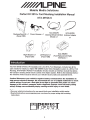
Perfect Fit 201 0+ Ford Mustang Installation Manual
KTX-MTG8-S
Mustang Dash Kit x 1
(Panel7295)
KCX-SWCFD
KCX-ANTB3
Steering Wheel Interface Antenna Adapter
Module x 1
x1
Power Harness x 1
Right Bracket x 1
(Panel 7297)
Left Bracket x 1
(Panel 7296)
KCX-RRMFD
(Ford Replacement Radio
Interface) x 1
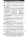
Introduction
This KTX-MTG8-S Perfect Fit installation kit is for 201 0+ Ford Mustang's. Included are all the
parts needed to install your Alpine INE-Z928HD Audio Video Navigation system in a 201 0+ Ford
Mustang. KTX-MTG8-S Perfect Fit installation kit also includes an interface module that allows
the Camaro's steering wheel remote control of the Alpine system. Refer to the individual instruction sections of this manual to remove your vehicle's factory radio and assemble the kit.
Caution! Disconnect your vehicle's negative battery terminel before the installation to
help prevent electrical damage. We recommend the use of a digital multimeter to check
vehicle wiring. Do not use a test light! A test light or grounded wire probe can cause
damage to the vehicle's computer and/or diagnostic systems. Avoid all factory airbag
wiring. Airbags can accidentally deploy causing serious injury or even death.
Notes:
• See your vehicle's instructions for any special tools your installation might require.
• Read all instructions accompanying your car stereo for proper wiring and mounting
instructions
1
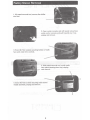
Factory Stereo Removal
1. With panel removal tool, remove the shifter
trim bezel.
2. Open center console and with panel removal tool,
unclip center console and pull towards rear of car,
unplug and remove.
3. Extract (2) 7mm screws securing bottom of radio
face panel under A/C controls.
4. With panel removal tool, unclip radio
face panel (starting from top), unplug
and remove.
5. Extract (4) 7mm screws securing radio motor/
chassis assembly, unplug and remove.
2
Mounting The Stereo
1. Attach panels 7296 and 7297 to the Alpine head unit
using the supplied screws (that come with the head unit).
Panel7296
2. Connect the supplied Plug-and-play wiring
harness.
3. Hook the Yellow/Blue wire to the Parking Brake
(-) in the center console. Hook the Yellow/Black
wire to the Foot Brake(+) at switch above pedal.
4. Connect and mount the stereo in the dash. (The
main kit panel mounts to the dash over the stereo.
5. Connect the HVAC controls. Panel7295 mounts
to the dash over the radio.
3
Climate & Convenience Controls
The Touch Screen Interface replaces the factory climate & convenience controls built into the OEM Ford
Radio/Dash panel. This solution provides improved ergonomics while adding touch screen capabilities
unique to this system. Read the following sections to familiarize yourself with the operating controls and
settings.
Figure 1
Control Panel Button Layout
2\--~r--
3>--+-++-- l)
---H-+----t 7
0
1. Fan Speed Up
2. Fan Speed Down
3. Air Conditioning On/Off
4. Climate Power On/Off
5.
6.
7.
8.
Defrost
Rear Defogger
Re-circulate •
SET {Settings)
Figure 2
Home TFT Color Touch Screen Layout
1. Air Temp Up
2. Air Temp Down
3. Max AIC On/Off
4. Driver's Heated Seat
5. Fan Speed Indicator
6. Pass Heated Seat
7. Vent Mode
Temp
Range
Power
Press the Power button {Fig.1, #4) to toggle the climate controls On or Off.
SET
Settings Menu Access
Press the SET button {Fig.1, #8) to access touch screen, vehicle features and other
settings. See "Display Screen" or "Vehicle Feature/Settings" sections for additional
information.
"Display Screen" or "Vehicle Feature/Settings" sections for additional information.
4
Climate & Convenience Controls (Continued)
Fan Speed Control
To increase fan speed, press the fan speed UP button on the control panel (pg. 4, Fig. 1, #1
). On the color TFT touch screen a graphic level indicator will move up indicating the current
fan speed (pg. 4, Fig. 2, #1 0). There are a total of 12 fan speed increments from completely
off to maximum.
,
-
To decrease fan speed, press the fan speed DOWN button on the control panel (pg. 4, Fig.
1, #2). On the color TFT touch screen a graphic level indicator will move down indicating
the current fan speed (pg. 4, Fig. 2, #1 0). Continue pressing the DOWN button to turn fan
completely off.
...
Temperature Control
Use the UP and DOWN arrows (pg. 4, Fig. 2, #1 & #2) on the color TFT touch screen to adjust vehicle air
temperature. Touch the Red <Up> arrow to increase air temp. Touch the Blue <Down> arrow to decrease
air temp. The temperature indicator will move up or down indicating the current temperature level. The
temperature range is color-coded: Red indicates warmer air and Blue indicates cooler air.
Air Flow I Vent Control
Touch the vent control mode (pg. 4,
Fig. 2, #9) on the color TFT touch
screen to toggle through the current
vent mode. Graphics are displayed
according to the selected vent and
airflow pattern.
e
-.~~
-. e
... II
Air is directed to
the instrument
Panel vent outlets
Air is directed to
the instrument
panel vent outlets
and the floor vent
outlets
e
\l~
~-
... ~
Air is directed
to tlthet floor vent
ou e s
Air will be
directed to the
windshield and
floor and/or side
vent outlets
Defog I Defrost Control
Touch the Defog (pg. 4, Fig. 1, #5) on the Color TFT touch screen to turn Defog On or Off.
This configuration clears windows of fog or moisture. Air will be directed to the windshield
and floor outlets.
·
Touch the Rear window defogger (pg. 4, Fig. 1, #6) on the Color TFT touch screen to turn the
rear window defogger on or off. The rear window defogger turns off automatically 12 minutes.
It can also be turned off by turning the ignition to ACC (ACCESSORY) or OFF position. If
turned on again it runs for 6 minutes before turning off. At higher vehicle speeds, the rear
defogger can stay on continuously.
Note: For best results clear the windows of snow or ice before defrost settings. DO NOT
OPERATE VEHICLE UNTIL WINDOWS ARE CLEAR!
Air Conditioning
To turn the air conditioning ON or OFF press AIC button on the control panel (pg. 4, Fig. 1,
#3). A Blue indicator light turns on. If the fan is turned off or the outside temperature falls
below freezing, the air conditioning will not work. The air conditioning might automatically
come on when Defrost mode is selected.
A
MAX¥
Touch the MAX A/C button (pg. 4, Fig. 2, #3) on the color TFT touch screen to turn on Max
A/C. Maximum cooling will occur with the temperature is adjusted to lowest cold setting and
the Fan speed is set at maximum. MAX A/Cis used to cool the car down as quickly as possible. Touct"l_the Max A/C button again to return to the previous Fan speed and temp setting.
Touch the Re-circulate button (pg. 4, Fig. 1, #7) on the color TFT touch screen to turn on
recirculation. Air will be re-circulated inside the vehicle. This mode helps to quickly cool the
air inside the vehicle or prevent outside air and odors from entering. Operating recirculation
mode while the A/C is off increases humidity and may cause the windows to fog. Recirculation is not available in the Defrost or Defog modes.
Heated Seats
Touch the driver's seat heater (pg. 4, Fig. 2, #4) button on the color TFT touch screen to turn
on the driver's seat heater. The engine must be running to use heated seats. A Button graphic
will show the level of heat selected: Two lights = high or one light = low). Press the button repeatedly to cycle through the temperature settings or to turn the heated seat OFF. Touch the
passenger's seat heater (pg. 4, Fig. 2, #6) button on the color TFT touch screen to turn on the
Passenger's seat heater. The engine must be running to use heated seats. A button graphic
will show the level of heat selected: Two lights high or one light low). Press the button
repeatedly to cycle through the temperature settings or to turn the heated seat OFF.
=
5
=
Display Screen Settings
Figure 3
Settings Home Screen Layout
...
-
\;/',.
Brightness
DAY
NIGHT
...
-
J
AUTO
Version Number
1. Display Settings
2. Back/Return
3. Day Theme Setting (Override)
4. Night Theme Setting (Override)
5. Auto Theme Setting (Vehicle-controlled)
6. Brightness Control (TFT Screen)
7. Overview Window
Other: Software version number appears
on lower left corner of set screen
SETTINGS MENU
Press the "Set" button (Fig. 1, #8) on the control panel to access the user controlled features and
settings. The "Settings" Home Screen will appear (Fig. 3) above.
DISPLAY TAB (Default Settings Screen)
Touch the "Display" Tab (Fig. 3, #1) to access various settings for the Touch Screen.
RETURN BUTTON
Touch the return button (Fig. 3, #2) to exit settings mode.
DAY THEME
Touch the "DAY" button (Fig. 3, #3) to assign Daytime color theme for the Color TFT touch screen.
This setting will keep the display with light colored background regardless of outside environment
(overrides Factory control).
NIGHT THEME
Touch the "NIGHT" button (Fig. 3, #4) to assign Nighttime color theme for the Color TFT touch
screen. This setting will keep the display with dark colored background regardless of outside
environment (overrides Factory control).
AUTO THEME (Default)
Touch the "AUTO" button (Fig. 3, #5) to assign Automatic (Factory) control of the TFT color theme.
This setting will keep Data-controlled switching color theme according to the outside environment.
(Light for Daytime I Dark for Nighttime).
BRIGHTNESS
Touch the"+"!"-" Brightness buttons (Fig. 3, #6) to adjust the Brightness of the Color TFT touch
screen.
PREVIEW WINDOW
Provides a quick preview of DAY/NIGHT setting changes (Fig. 3, #7).
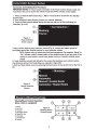
Initial HVAC Screen Setup
Connection And Initialization Procedure:
IMPORTANT NOTE! To ensure proper operation of the Touch-screen climate control, you
must first set the unit to match the vehicle model and HVAC climate control system!
1. Press and Hold the SET button (Fig. 1, #8) for 10 seconds to access the Car Selection
Screen (Fig. 4)
2. From the Vehicle Setup Screen choose your vehicle: Mustang.
3. Touch the White colored Model listing and the text will turn to Red indicating your
selection. (Fig. 4 #2)
Figure 4
Vehicle Selection
Screen·Layout
4. Next, from the Option group selection screen (Fig. 5), choose the feature group that
accurately matches the original options for your particular vehicle:
NOTE: Options vary by vehicle trim level and equipment. For example "Manual" or
"Auto" climate control. Heated seats or Non-heated seats. If you are unsure of the
options on your vehicle, consult your dealer invoice or vehicle's original owner's
..
manual.
5. Touch the White colored text listing for the screen that matches your vehicle's options.
The White text will turn Red indicating your selection. (Fig.5, #2).
6. Exit the Vehicle Setup screen by pressing the back arrow in the top left corner (See Fig. 5,
#1).
Figure 5
Options Selection
Screen
Steering Wheel Controls
Steering Wheel Control Operation
(when vehicle is equipped)
1.
2.
3.
4.
5.
6.
7.
8.
Mute
Not Used
Not Used
Seek/Track Down
Seek/Track Up
Volume Up
Volume Down
Source
Figure 6
Steering Wheel
Control Layout
7
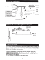
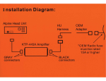
Wiring Harness Diagram
To Head Unit
Power Connector
I~
To Ford Vehicle Harness- [m~~~~~~
L~
INE-Z928HD
Audio
Video
Navigation
System
To foot Brake(+) at
switch above pedal
To aftermarket amplifier
remote turn on
To Steering Remote
Input (Pigtail)
F====fi
To Steering Wheel Remote
Module
HVAC/Touch Screen Wiring Harness Diagram
USB for Interface
firmware update
ONLY
w
.....
:;)
c
0
~
To Mustang
HVAC harness
Liability Disclaimer
Due to changes in design and manufacturing that may occur with your specific vehicle, it is important that
you do not rely solely on vehicle information contained in this installation manual, such as dash disassembly, wire harness, and codes. Such information should be confirmed with the vehicle manufacturer. Alpine
Electronics, Inc. and its affiliated companies is not responsible for damage that may occur to you or your
automobile during the installation of the Perfect Fit Kit.
If you have any further questions, feel free to contact Alpine Tech Support at 1-800-NAV-HELP.
ALPINE ELECTRONICS OF AMERICA, INC., 19145 Gramercy Place, Torrance, CA 90501, U.S.A
ALPINE ELECTRONICS OF CANADA, INC., 777 Supertest Road, Toronto, Ontario M3J 2M9, Canada
Do not send products to these addresses.
Call the toll free number or visit the website to locate ·a service center.
8
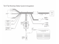
Tech Tip: Mustang Shaker System Integration
INE-XXXX
INE-XXXX
To Ford Vehicle
Harnesses
AVN
system
To aftermarket
amplifier remote
turn on
To Foot Brake
(+)at switch above
pedal
Blue/White
KCX-RRMFD
Yellow/Black
Ford Radio
Replacement
Module
~
I
Factory OEM AUX Port
(Below rad io)
~
To Parking Brake
(-)at the parking
brake in drivers kick
panel
Yellow/ Blue
To Steering Remote
Input (Pigtail)
KCX-SWCFD
Ford Steering
Wheel Control
Module
For Shaker systems add 200K n resistor
to all speaker leads
--1~... -~-
PER FEC T FIT™ INST ALL ATIO N KIT
PERFECT
I
~0'1:?
SOLU
•
T
ION
S
•
KIT D' INSTALLATION PERFECT FIT™
1 KTX-MTGS
2010-UP
FORD MUSTANG
INSTALLATION KIT
(NON-NAVIGATION)
KTX-MTGS
2010-UP
FORD MUSTANG
INSTALLATION KIT
(NON-NAVIGATION)
ALPINE ELECTRONICS OF AMERICA, INC.
www.alpine.c om
DRIVING MOBILE MEDIA SOLUTIONS
Mobile Media Solutions
o
o
o
o
PERFECT SHAPE AND COLOR MATCH TO OEM DASH FOR FACTORY FIT
INCLUDES ALPINE-TO-VEHICLE HARNESS FOR PLUG-AND-PLAY INSTALLATION
INCLUDES RETAINING CLIPS
INSTRUCTION MANUAL WITH STEP-BY-5TEP INSTALLATION OF ALL COMPONENTS
CORRESPONDANCE PARFAITE AVEC LA FORME ET COULEUR DU TABLEAU DE BORD DE L'EQUIPEMENTIER POUR UN
ASPECT SORTIE D'USINE
o COMPREND UN HARNAIS POUR CONNECTER L'UNITE ALPINE AU VEHICULE POUR UNE INSTALLATION PR~TE A L'EMPLOI
o COMPREND LES CLIPS DE MAINTIEN
o MANUEL D'INSTRUCTIONS DETAILLANT L'INSTALLATION PAS A PAS DE TOUS LES COMPOSANTS
o
~LPINE~
Mobile Media Solutions
Alpine, Alpine Mobile Media Solutions, Driving Mobile Media Solutions are registered trademarks of Alpine Electronics, Inc.
Alpine, Alpine Mobile Media Solutions, Driving Mobile Media Solutions sont des marques deposees d'Aipine Electronics, Inc.
MADE IN CHINA
FABRIOUE EN CHINE