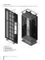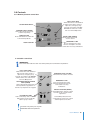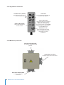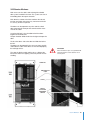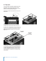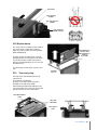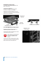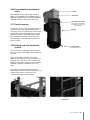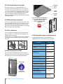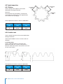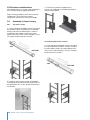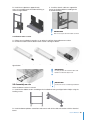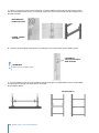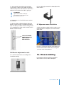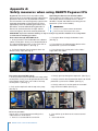
1
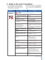
AVANTI SERVICE LIFT
User’s, Installation and Maintenance Manual
Model Service Lift Pegasus
Date of publication:
1st CE Edition: 05/2012
Revision 3: 15/11/12
Manufacturer:
Avanti Wind Systems SL
Poligono Industrial Centrovia
Calle Los Angeles n°88 Nave 1
50198 La Muela (Zaragoza)
Spain
P: (+34) 976 149 524
F: (+34) 976 149 508
E:[email protected]
I:www.avanti-online.com
Avanti Wind Systems, Inc.
5150 Towne Drive
New Berlin
Wisconsin 53151
USA
P: (+1) 262 641 9101
F: (+1) 262 641 9161
Avanti Wind Systems
Building 4, No, 518,
Gangde Road, XiaokunshanTown
Songjiang District, 201614 Shanghai
China
P: (+86) 21 5785 8811
F: (+86) 21 5785 8815
Sales & Service:
Australia
Avanti Wind Systems PTY LTD P: +61 (0) 7 3902 1445
China
Avanti Wind Systems P: +86 21 5785 8811
Denmark
Avanti Wind Systems A/S P: +45 4824 9024
Germany
Avanti Wind Systems GmbH P: +49 (0) 41 21-7 88 85 – 0
Spain
Avanti Wind Systems SL P: +34 976 149 524
UK
Avanti Wind Systems Limited P: +44 0 1706 356 442
USA
Avanti Wind Systems, Inc P: +1 (262) 641-9101
India
Avanti Wind Systems, PL P: +91 44 6455 5911
Only trained people may use this lift.
This manual must be available to staff at all times during installation, maintenance and operation.
Additional copies are available from the manufacturer upon request.
All measurements are indicative only and subject to change without notice.
Contents
Page
1 Limited Warranty . . . . . . . . . . . . . . . . . . . . . . . . . . . . . . . . . . . . . . . . . . . . . . . . . . . . . . . . . . . . . . . 6
2Cautions . . . . . . . . . . . . . . . . . . . . . . . . . . . . . . . . . . . . . . . . . . . . . . . . . . . . . . . . . . . . . . . . . . . . . . 7
2.1 Symbols used in this manual . . . . . . . . . . . . . . . . . . . . . . . . . . . . . . . . . . . . . . . . . . . . . . . . . . . 8
2.2 Cautions . . . . . . . . . . . . . . . . . . . . . . . . . . . . . . . . . . . . . . . . . . . . . . . . . . . . . . . . . . . . . . . . . . . 9
3Description . . . . . . . . . . . . . . . . . . . . . . . . . . . . . . . . . . . . . . . . . . . . . . . . . . . . . . . . . . . . . . . . . . . . 9
3.1 Purpose . . . . . . . . . . . . . . . . . . . . . . . . . . . . . . . . . . . . . . . . . . . . . . . . . . . . . . . . . . . . . . . . . . . . 9
3.2 Scope . . . . . . . . . . . . . . . . . . . . . . . . . . . . . . . . . . . . . . . . . . . . . . . . . . . . . . . . . . . . . . . . . . . . . 9
3.3 Exclusions . . . . . . . . . . . . . . . . . . . . . . . . . . . . . . . . . . . . . . . . . . . . . . . . . . . . . . . . . . . . . . . . . . 9
3.4 Technical specifications . . . . . . . . . . . . . . . . . . . . . . . . . . . . . . . . . . . . . . . . . . . . . . . . . . . . . . 10
3.4.1 General specifications service lift . . . . . . . . . . . . . . . . . . . . . . . . . . . . . . . . . . . . . . . . . 10
3.4.2 Traction system specifications . . . . . . . . . . . . . . . . . . . . . . . . . . . . . . . . . . . . . . . . . . . . 10
3.4.3 Cabin dimensions . . . . . . . . . . . . . . . . . . . . . . . . . . . . . . . . . . . . . . . . . . . . . . . . . . . . . . 10
3.4.4 Power and control cable . . . . . . . . . . . . . . . . . . . . . . . . . . . . . . . . . . . . . . . . . . . . . . . . . 10
3.4.5 Mast sections . . . . . . . . . . . . . . . . . . . . . . . . . . . . . . . . . . . . . . . . . . . . . . . . . . . . . . . . . 10
3.5 Service lift overview . . . . . . . . . . . . . . . . . . . . . . . . . . . . . . . . . . . . . . . . . . . . . . . . . . . . . . . . . . 11
3.6 General arrangement of Pegasus lift inside a generic wind turbine tower . . . . . . . . . . . . . . 12
3.7 Service lift dimensions . . . . . . . . . . . . . . . . . . . . . . . . . . . . . . . . . . . . . . . . . . . . . . . . . . . . . . . 13
3.8 Main frame . . . . . . . . . . . . . . . . . . . . . . . . . . . . . . . . . . . . . . . . . . . . . . . . . . . . . . . . . . . . . . . . . 14
3.9 Controls . . . . . . . . . . . . . . . . . . . . . . . . . . . . . . . . . . . . . . . . . . . . . . . . . . . . . . . . . . . . . . . . . . . 15
3.9.1 Bottom platform control box . . . . . . . . . . . . . . . . . . . . . . . . . . . . . . . . . . . . . . . . . . . . . . 15
3.9.2 Cabin control box . . . . . . . . . . . . . . . . . . . . . . . . . . . . . . . . . . . . . . . . . . . . . . . . . . . . . . 15
3.9.3 Top platform control box . . . . . . . . . . . . . . . . . . . . . . . . . . . . . . . . . . . . . . . . . . . . . . . . . 16
3.9.4 Mid tower junction box . . . . . . . . . . . . . . . . . . . . . . . . . . . . . . . . . . . . . . . . . . . . . . . . . . 16
3.10 Service lift doors . . . . . . . . . . . . . . . . . . . . . . . . . . . . . . . . . . . . . . . . . . . . . . . . . . . . . . . . . . . . 17
3.11 Top hatch . . . . . . . . . . . . . . . . . . . . . . . . . . . . . . . . . . . . . . . . . . . . . . . . . . . . . . . . . . . . . . . . . 18
3.12 Bottom hatch . . . . . . . . . . . . . . . . . . . . . . . . . . . . . . . . . . . . . . . . . . . . . . . . . . . . . . . . . . . . . . 19
3.13 Top safety stop . . . . . . . . . . . . . . . . . . . . . . . . . . . . . . . . . . . . . . . . . . . . . . . . . . . . . . . . . . . . 19
3.14 Bottom safety stop . . . . . . . . . . . . . . . . . . . . . . . . . . . . . . . . . . . . . . . . . . . . . . . . . . . . . . . . . 20
3.15 Emergency limit stop switch . . . . . . . . . . . . . . . . . . . . . . . . . . . . . . . . . . . . . . . . . . . . . . . . . 20
3.16 Top and bottom mechanical stops . . . . . . . . . . . . . . . . . . . . . . . . . . . . . . . . . . . . . . . . . . . . 21
3.17 Traction system . . . . . . . . . . . . . . . . . . . . . . . . . . . . . . . . . . . . . . . . . . . . . . . . . . . . . . . . . . . . 21
3.18 Guiding and anti-derailment system . . . . . . . . . . . . . . . . . . . . . . . . . . . . . . . . . . . . . . . . . . . 22
3.19 Overload detection system . . . . . . . . . . . . . . . . . . . . . . . . . . . . . . . . . . . . . . . . . . . . . . . . . . 22
3.20 Manual descent system . . . . . . . . . . . . . . . . . . . . . . . . . . . . . . . . . . . . . . . . . . . . . . . . . . . . . 22
3.21 Rest platforms . . . . . . . . . . . . . . . . . . . . . . . . . . . . . . . . . . . . . . . . . . . . . . . . . . . . . . . . . . . . 22
3.22 Anchor points for PPE . . . . . . . . . . . . . . . . . . . . . . . . . . . . . . . . . . . . . . . . . . . . . . . . . . . . . . 22
3.23 Information signs and documents . . . . . . . . . . . . . . . . . . . . . . . . . . . . . . . . . . . . . . . . . . . . . 22
4 Lift Operation . . . . . . . . . . . . . . . . . . . . . . . . . . . . . . . . . . . . . . . . . . . . . . . . . . . . . . . . . . . . . . . . . 23
4.1 Good use . . . . . . . . . . . . . . . . . . . . . . . . . . . . . . . . . . . . . . . . . . . . . . . . . . . . . . . . . . . . . . . . . . 23
4.2 Prohibited uses . . . . . . . . . . . . . . . . . . . . . . . . . . . . . . . . . . . . . . . . . . . . . . . . . . . . . . . . . . . . . 23
4.3 Operation from inside the cabin . . . . . . . . . . . . . . . . . . . . . . . . . . . . . . . . . . . . . . . . . . . . . . . 23
4.4 Operation from bottom platform . . . . . . . . . . . . . . . . . . . . . . . . . . . . . . . . . . . . . . . . . . . . . . . 23
4.5 Operation from top platform . . . . . . . . . . . . . . . . . . . . . . . . . . . . . . . . . . . . . . . . . . . . . . . . . . 23
4.6 Landing alignment . . . . . . . . . . . . . . . . . . . . . . . . . . . . . . . . . . . . . . . . . . . . . . . . . . . . . . . . . . 23
4.7 Enter and exit cabin . . . . . . . . . . . . . . . . . . . . . . . . . . . . . . . . . . . . . . . . . . . . . . . . . . . . . . . . . 23
4.7.1 Double door . . . . . . . . . . . . . . . . . . . . . . . . . . . . . . . . . . . . . . . . . . . . . . . . . . . . . . . . . . . 23
4.7.2 Top / Bottom hatch . . . . . . . . . . . . . . . . . . . . . . . . . . . . . . . . . . . . . . . . . . . . . . . . . . . . . 23
4.8 Emergency stop . . . . . . . . . . . . . . . . . . . . . . . . . . . . . . . . . . . . . . . . . . . . . . . . . . . . . . . . . . . . 24
4.9 Manual operation . . . . . . . . . . . . . . . . . . . . . . . . . . . . . . . . . . . . . . . . . . . . . . . . . . . . . . . . . . . 24
4.10 Rest platforms . . . . . . . . . . . . . . . . . . . . . . . . . . . . . . . . . . . . . . . . . . . . . . . . . . . . . . . . . . . . . 24
4.11 Service ladder . . . . . . . . . . . . . . . . . . . . . . . . . . . . . . . . . . . . . . . . . . . . . . . . . . . . . . . . . . . . . 24
5 Out Of Service . . . . . . . . . . . . . . . . . . . . . . . . . . . . . . . . . . . . . . . . . . . . . . . . . . . . . . . . . . . . . . . . 24
4
AVANTI Service Lift for Wind Turbines
6Maintenance . . . . . . . . . . . . . . . . . . . . . . . . . . . . . . . . . . . . . . . . . . . . . . . . . . . . . . . . . . . . . . . . . . 25
6.1 Maintenance planning . . . . . . . . . . . . . . . . . . . . . . . . . . . . . . . . . . . . . . . . . . . . . . . . . . . . . . . 26
6.2 Daily inspection by the supervisor . . . . . . . . . . . . . . . . . . . . . . . . . . . . . . . . . . . . . . . . . . . . . 26
6.3 Yearly inspection . . . . . . . . . . . . . . . . . . . . . . . . . . . . . . . . . . . . . . . . . . . . . . . . . . . . . . . . . . . 26
6.3.1 Pinions . . . . . . . . . . . . . . . . . . . . . . . . . . . . . . . . . . . . . . . . . . . . . . . . . . . . . . . . . . . . . . . 26
6.3.2 Ladder rack . . . . . . . . . . . . . . . . . . . . . . . . . . . . . . . . . . . . . . . . . . . . . . . . . . . . . . . . . . . 27
6.3.3 Counter guiding roller . . . . . . . . . . . . . . . . . . . . . . . . . . . . . . . . . . . . . . . . . . . . . . . . . . . 27
6.3.4 Guiding roller . . . . . . . . . . . . . . . . . . . . . . . . . . . . . . . . . . . . . . . . . . . . . . . . . . . . . . . . . . 27
6.3.5 Torques assurance . . . . . . . . . . . . . . . . . . . . . . . . . . . . . . . . . . . . . . . . . . . . . . . . . . . . . 28
6.3.6 Motor group . . . . . . . . . . . . . . . . . . . . . . . . . . . . . . . . . . . . . . . . . . . . . . . . . . . . . . . . . . . 28
6.3.6.1 Gear box . . . . . . . . . . . . . . . . . . . . . . . . . . . . . . . . . . . . . . . . . . . . . . . . . . . . . . . . 28
6.3.6.2 Centrifugal brake . . . . . . . . . . . . . . . . . . . . . . . . . . . . . . . . . . . . . . . . . . . . . . . . . 28
6.3.6.3 Motor brake . . . . . . . . . . . . . . . . . . . . . . . . . . . . . . . . . . . . . . . . . . . . . . . . . . . . . 28
6.4 Ordering spare parts . . . . . . . . . . . . . . . . . . . . . . . . . . . . . . . . . . . . . . . . . . . . . . . . . . . . . . . . 28
7 Repair in the event of breakdown . . . . . . . . . . . . . . . . . . . . . . . . . . . . . . . . . . . . . . . . . . . . . . . . 29
8 Transport and storage . . . . . . . . . . . . . . . . . . . . . . . . . . . . . . . . . . . . . . . . . . . . . . . . . . . . . . . . . 30
9Installation . . . . . . . . . . . . . . . . . . . . . . . . . . . . . . . . . . . . . . . . . . . . . . . . . . . . . . . . . . . . . . . . . . . 30
9.1 Interface requirements . . . . . . . . . . . . . . . . . . . . . . . . . . . . . . . . . . . . . . . . . . . . . . . . . . . . . . . 30
9.1.1 Heigth and angle . . . . . . . . . . . . . . . . . . . . . . . . . . . . . . . . . . . . . . . . . . . . . . . . . . . . . . . 30
9.1.2 Lifetime and frequency of operation . . . . . . . . . . . . . . . . . . . . . . . . . . . . . . . . . . . . . . . 30
9.1.3 Lift holes at platforms and air gap to tower parts . . . . . . . . . . . . . . . . . . . . . . . . . . . . 30
9.1.4 Tower support brackets . . . . . . . . . . . . . . . . . . . . . . . . . . . . . . . . . . . . . . . . . . . . . . . . . 31
9.1.5 Wind turbine electrical supply requirements . . . . . . . . . . . . . . . . . . . . . . . . . . . . . . . . 31
9.1.6 Other requirements . . . . . . . . . . . . . . . . . . . . . . . . . . . . . . . . . . . . . . . . . . . . . . . . . . . . . 31
9.2 Cautions . . . . . . . . . . . . . . . . . . . . . . . . . . . . . . . . . . . . . . . . . . . . . . . . . . . . . . . . . . . . . . . . . . 31
9.3 Previous considerations . . . . . . . . . . . . . . . . . . . . . . . . . . . . . . . . . . . . . . . . . . . . . . . . . . . . . . 32
9.4 Assembly in tower factory . . . . . . . . . . . . . . . . . . . . . . . . . . . . . . . . . . . . . . . . . . . . . . . . . . . . 32
9.4.1 Top tower section . . . . . . . . . . . . . . . . . . . . . . . . . . . . . . . . . . . . . . . . . . . . . . . . . . . . . . 32
9.4.2 Intermediate tower sections . . . . . . . . . . . . . . . . . . . . . . . . . . . . . . . . . . . . . . . . . . . . . 32
9.4.3 Bottom tower section . . . . . . . . . . . . . . . . . . . . . . . . . . . . . . . . . . . . . . . . . . . . . . . . . . . 33
9.5 Assembly on site . . . . . . . . . . . . . . . . . . . . . . . . . . . . . . . . . . . . . . . . . . . . . . . . . . . . . . . . . . . . 33
9.6 Electric adjustment on site . . . . . . . . . . . . . . . . . . . . . . . . . . . . . . . . . . . . . . . . . . . . . . . . . . . 35
9.7 Alignment labels installation . . . . . . . . . . . . . . . . . . . . . . . . . . . . . . . . . . . . . . . . . . . . . . . . . . 35
10Disassembling . . . . . . . . . . . . . . . . . . . . . . . . . . . . . . . . . . . . . . . . . . . . . . . . . . . . . . . . . . . . . . . . 35
Appendix A Safety measures when using AVANTI Pegasus lifts . . . . . . . . . . . . . . . . . . . . . . . . . . 36
Appendix B Final installation and maintenance check list . . . . . . . . . . . . . . . . . . . . . . . . . . . . . . . 37
Appendix C Maintenance record . . . . . . . . . . . . . . . . . . . . . . . . . . . . . . . . . . . . . . . . . . . . . . . . . . . . 39
User’s Manual
5
1. Limited Warranty
Avanti Wind Systems A/S warrants that commencing from the date of shipment to the
Customer and continuing for a period of the
longer of 365 days thereafter, or the period set
forth in the standard Avanti warranty, the Avanti
service lift (“Product”) described in this Manual
will be free from defects in material and workmanship under normal use and service when
installed and operated in accordance with the
provisions of this Manual.
This warranty is made only to the original user
of the Product. The sole and exclusive remedy
and the entire liability of Avanti under this
limited warranty, shall be, at the option of
Avanti, a replacement of the Product (including
incidental and freight charges paid by the
Customer) with a similar new or reconditioned
Product of equivalent value, or a refund of the
purchase price if the Product is returned to
Avanti, freight and insurance prepaid. The
obligations of Avanti are expressly conditioned
upon return of the Product in strict accordance
with the return procedures of Avanti.
This warranty does not apply if the Product (i)
has been altered without the authorization of
Avanti or its authorized representative; (ii) has
not been installed, operated, repaired, or
maintained in accordance with this Manual or
other instructions from Avanti; (iii) has been
subjected to abuse, neglect, casualty, or
negligence; (iv) has been furnished by Avanti to
Customer without charge; or (v) has been sold
on an “AS-IS” basis.
* Avanti service lift (“Product”)
6
AVANTI Service Lift for Wind Turbines
Except as specifically set forth in this Limited
Warranty,
ALL EXPRESS OR IMPLIED CONDITIONS,
REPRESENTATIONS AND WARRANTIES,
INCLUDING, BUT NOT LIMITED TO, ANY
IMPLIED WARRANTY OR CONDITION OF
MERCHANTABILITY, FITNESS FOR A
PARTICULAR PURPOSE, NON-INFRINGEMENT, SATISFACTORY QUALITY, COURSE OF
DEALING, LAW, USAGE OR TRADE PRACTICE
ARE HEREBY EXCLUDED TO THE MAXIMUM
EXTENT PERMITTED BY APPLICABLE LAW
AND ARE EXPRESSLY DISCLAIMED BY
AVANTI. IF, PURSUANT TO ANY APPLICABLE
LAW, TO THE EXTENT AN IMPLIED WARRANTY CANNOT BE EXCLUDED AS PROVIDED IN
THIS LIMITED WARRANTY, ANY IMPLIED
WARRANTY IS LIMITED IN TIME TO THE SAME
DURATION AS THE EXPRESS WARRANTY
PERIOD SET FORTH ABOVE. BECAUSE SOME
STATES DO NOT PERMIT LIMITATIONS ON
THE DURATION OF IMPLIED WARRANTIES,
THIS MAY NOT APPLY TO A GIVEN CUSTOMER. THIS LIMITED WARRANTY GIVES CUSTOMER SPECIFIC LEGAL RIGHTS, AND
CUSTOMER MAY HAVE OTHER LEGAL
RIGHTS UNDER APPLICABLE LAWS.
This disclaimer shall apply even if the express
warranty fails of its essential purpose.
In any cases of dispute the English original shall
be taken as authoritative.
2. Explanation of symbols used in this manual
2.1 Symbols used in this manual
Symbol
Signal word
Meaning
Possible injury if not observed
IMMEDIATE or
possibly imminent
danger:
Death or severe injury!
Safety instructions
STOP
DANGER!
DANGER!
CAUTION!
IMMEDIATE or
possibly imminent
danger of hazardous
voltage:
Death or severe injury!
Potentially hazardous
situation:
Light injury or material damage.
ATTENTION!
Potentially dangerous
situation:
Damage to equipment or workplace
IMPORTANT!
Useful tips for optimum
working procedure
None
Additional instructions
!
Order
Reference to written
specification/documentation
User’s Manual
7
2.2 Cautions
CAUTION!
Avoid injury – follow all instructions!
m)All tests/repairs of electrical installations may only
be performed by qualified electricians.
a) Installation and/or maintenance and/or operation of
the service lift and its suspension may be performed
only by qualified personnel hired by the employer for
the job at hand.
n) All repairs to the motor group: gear box, centrifugal
brake, motor brake and instead of supporting parts
may be performed only be qualified fitters.
b) The personnel must be at least 18 years of age. The
staff must be familiar with the relevant accident
prevention instructions and must have received proper
training in these.
c) Personnel are obliged to read and understand this
User’s Manual.
d) Access to cabin shall be done in pairs carrying
reliable communication equipment and each user shall
at all times wear PPE ( safety helmet, full body harness,
shock absorber, lanyard and slider).
e) A copy of the User’s Manual must be handed out to
the personnel and must always be available for
reference.
f) If more than one person is entrusted with one of the
above tasks, the employer shall appoint a supervisor in
charge of the operation.
o) If any supporting parts have been repaired or
replaced, the operational safety of the system must be
tested and verified by an expert.
p) Use of non-original parts will render the manufacturer’s warranty void and make the CE approval invalid.
This particulary applies to the motor group.
q) No modification, extension or reconstruction of the
service lift is allowed without the manufacturer’s prior
written consent.
r) No warranty is provided against damage resulting
from reconstruction or modification of equipment or
use of non-original parts which are not approved by
the manufacturer.
s) Before using the lift an inspection by the authorised
security organisation must be carried out.
g) Whenever installation, ascending, and/or descending involve a danger of falling, all personnel inside the
danger area must wear personal protective equipment
which will prevent them from falling by means of a
safety system secured to the building.
t) The lift must be inspected at least once a year by
an expert being trained by AVANTI. The Pegasus
service lift is designed for a lifetime of 20 years with a
operating frequency of approximately 12.5 h/year of
250 h during lift. In case of the operating frequency
is higher, service and inspections are required and
replacement of components might be necessary
according to the replacement criteria stated on the
maintenance manual.
h) Only pinions, ladder rack, motor groups, overload
detections system or original control system may be
used.
u) The service lift may not be used by persons who
are under the influence of alcohol or drugs which may
jeopardize working safety.
i) Electrical connection of the system must be made in
accordance with EN 60204-1 which shall include
necessary protection against indirect contacts according to the earthing system being used.
v) Do not use the service lift in case of more than 18
m / s wind speed.
STOP DANGER!
j) Prior to mounting all parts must be tested to ensure
their completeness and full functionality.
k) Self-locking nuts must be used at all times and the
following must always be observed:
a. The screw must extend from the nut by at least half
of the thread diameter.
b. The nut may not be used once it has become
possible to loosen by hand!
l) If any damage or faults are found during operation, or
if circumstances arise jeopardizing safety:
a. Immediately interrupt the work in progress and
notify the supervisor or employer!
8 AVANTI Service Lift for Wind Turbines
The tower owner must verify the need for third
party service lift inspections with the local
authority and comply with the
standards specified.
If the service lift is not in the platform, the
routes of entry and exit to the turbine ensuring compliance with the preventive measures
to avoid falls from the landings, must be
insured by the wind turbine manufacturer.
3. Description
3.1 Purpose
3.3 Exclusions
The Service Lift described in this User’s Manual
serves the following purposes:
- Transportation of staff and material inside wind
turbine systems.
- Transportation for mounting, inspection and
repairs.
The service lift may be used to transport persons
plus their tools and equipment to the most
convenient height for performing work on the
tower.
Please read Cautions section for limitations and
exclusions of the service lift operation of the
service lift.
3.2 Scope
The system consists on a rack and pinion service
lift guided along a metal ladder and the necessary
accessories allowing the connection to the tower
and providing the control and safety functions
described in the manual. The accessories include:
mast supports (ties to the tower brackets), rest
platforms, mechanical stops, safe zone plates,
control stations and other electrical equipment. It
also includes the hardware necessary to make the
connections, labels and warning signs.
The mast sections, their supports and related
accessories may be assembled to the tower in the
tower factory and supplied later on site for final
installation. The cabin is supplied pre-assembled
and may be supplied to the tower factory or on site
directly. Final assembly, adjustment, installation
and verification of the service lift shall be made on
site.
The installation of the service lift shall only be made
by the manufacturer or by a company trained and
authorised by the manufacturer.
The system, as defined on this scope, is part of
machinery falling under Annex IV, section 17 of the
European Machinery directive and meets the
essential health and safety requirements. A
declaration of conformity of the complete system
integrated in the wind tower can only be issued
after the system has been fully incorporated. In
case the necessary information for the evaluation is
not supplied to Avanti, a declaration of incorporation shall be issued. The wind tower manufacturer
is responsible for ensuring full compliance of the
system once integrated in the tower in such case.
To do so, the instructions and requirements stated
in this manual shall be observed.
The service lift must not be used outdoor or in
potentially explosive atmospheres.
The equipment listed below is specifically out of
the scope and is needed for the safe integration
and use of the service lift. It shall be evaluated on
the tower manufacturer’s risk assessment on its
integration study, designed and supplied as
necessary:
- Fences to protect users from falling through the
service lift hole at landings. They shall at least
comply with EN 14122-3, have non slipping rails or
steps facilitating access to the lift at landings and
have no doors.
- Interlock systems for landing doors or hatches
(when existing) preventing any movement of the lift
if the door or hatch are not closed and locked.
- Emergency lighting along the tower and user
portable light / helmet light as cabin uses perforated sheet to allow tower light inside.
The pictures and sketches in this manual may
not reflect the product aesthetics, colours and
arrangement precisely. This has no impact on
the function or safety.
User’s Manual
9
3.4 Technical specifications
3.4.1 General specifications service lift
3.4.3 Cabin dimensions
Service lift
Cabin
Cabin type
Bucket type, front fence
(1.1 m) with double door
Service lift speed
19.4 m/min ± 10 % (50 Hz)
Cabin weight
225 Kg
Outer dimensions (W x D x H)
1060 x 715 x 2540 mm
Inner dimensions (W x D x H)
990 x 525 (680) x 2200 mm
Door opening (full) (W x H)
980 x 1120 mm
Top hatch dimensions (W x D)
600 x 400 mm
Bottom hatch dimensions (W x D)
600 x 400 mm
17.4 m/min ± 10 % (60 Hz)
Working load limit /
Nº persons (max)
250 Kg / 2 Persons
Travelling height
150 m
Operating
temperature
Standard
-15ºC to +60ºC
Low temperature
-25ºC to +40ºC
Survival temperature
-30ºC to +80ºC
Traction system type
Rack and pinion
Max. noise level
80 dB (A)
Power supply
3 kW, 16 A
3.4.4 Power & control cable
Power & Control cable
Type
Bottom platform
to juction box
18 G 2.5
Top platform
to junction box
8 G 1.5
Travelling cable
1 x 8 G 2.5 + 1 x 10 G 1.5
3 Phase 400V, 50Hz / 60Hz
IP protection
min. IP 54
Control voltage
24 VAC
Note: for special working conditions, check with the manufacturer
3.4.2 Traction system specifications
Travelling cable weight
(approx.)
0.6 Kg/m
3.4.5 Mast sections
Ladder rack (Mast)
Traction system / Motor group
Power
Gear box ratio
Dimensions
530 x 30 x 1489 mm / 530 x 30 x 2978
mm
Weight (per piece)
15 Kg / 30 Kg
Attachment distance
1 per mast section, max. 3000 mm
2 x 1.5 kW
1 : 15 (50 Hz)
1 : 20 (60 Hz)
Rack / Pinion module
6
Centrifugal brake limiting speed
24 m/min
Dimensions
220 x 225 x 580 mm
Weight by motor group
30 Kg
Motor speed
1400 rpm (50 Hz) –
1680 rpm (60 Hz)
Nominal current
2x3A
Start current
2 x 15 A
10 AVANTI Service Lift for Wind Turbines
3.5 Service lift overview
1
2
3
4 7
5
6
8
9
1.
2.
3.
4.
5.
Top safety stop
Top hatch
Double door
Main frame
User control box
6.
7.
8.
9.
Fixed front
Anchor point for PPE
Bottom hatch
Bottom safety stop
User’s Manual 11
3.6 General arrangement of Pegasus lift inside a generic wind turbine tower
1
2
3
5
15
8
6
9
4
7
10
11
13
14
12
INTERMEDIATE ARM FOR ELECTRIC CABLE
This bracket is screwed to one of the anchorages
of the installation at a suitable height to allow the
proper reeving of the electrical cable.
12 AVANTI Service Lift for Wind Turbines
1. User control box in top platform
2. Top platform
3. Top mechanical stop
4. Rest platform
5. Pegasus service lift
6.Anchorages
7. Junction box
8. Intermediate arm for electric cable
9. Intermediate platform
10.Travelling cable
11.Bottom platform control box
12.Fence-railing
13.Bottom platform
14.Bottom mechanical stop
15.Ladder rack
3.7 Service lift dimensions
User’s Manual 13
3.8 Main frame
The main frame is a welded steel structure. The traction and guiding system are bolted to the main frame.
2
1
6
7
5
3
1. Main frame
2. Guiding rollers top
3. Guiding rollers bottom
4. Evacuation ladder
5. Traction system/ 2 Motor groups
6. Anti- derailment brackets
7.Pinions
14 AVANTI Service Lift for Wind Turbines
4
3.9 Controls
3.9.1 Bottom platform control box
FAULT LIGHT (RED)
Shines when there is an activated
switch on the safety circuit i.e:
Open door, emergency stop
pressed, open hatch or the ON/
OFF buttons of the user control
box is not in the ON position
ON/OFF MAIN SWITCH
UP/DOWN LIGHTS (GREEN)
Shines when the lift is going up
or down respectively.
NOK
DOWN BUTTON
Press down button to call the lift
to the bottom platform.
OK
READY LAMP (GREEN)
Shines when the box has
electric current.
EMERGENCY STOP
Press to interrupt any control
function. Turn/pull to reset the
control after necessary verifications
HOUR COUNTER
3.9.2 Cabin control box
IMPORTANT!
User control box inside the cabin has control priority over control boxes at platforms.
FAULT LIGHT (RED)
Shines when there is an activated
switch on the safety circuit i.e:
Open door, emergency stop
pressed, open hatch or the ON/OFF
buttons of the user control box is
not in the ON position.
OVERLOAD LIGHT (YELLOW)
Shines when the cabin is overload
NOK
TOP AND BOTTOM PLATFORM
LIGHT (GREEN)
Shines when the lift reaches the
bottom platform, top platform or
bottom / top stop bars are engaged.
EMERGENCY STOP
Press to interrupt any control
function. Turn/pull to reset the
control after necessary
verifications.
ON/OFF SELECTOR (GREEN)
Select ON position, then the control
box has electric current and the
light shines.
UP/DOWN BUTTONS
Push continuously “UP” or “DOWN”
button, when you are inside the
cabin to go up or down.
!
Select OFF position, then the
control box has not electric current
and the light does not shine.
This button has priority over any UP/
DOWN BUTTON at the platforms.
User’s Manual 15
3.9.3 Top platform control box
UP/DOWN LIGHTS (GREEN)
Shines when the lift is going up
or down respectively.
UP BUTTON
Press continuously UP button to
call cabin to top platform.
NOK
READY LAMP (GREEN)
Shines when the box has
electric current.
OK
FAULT LIGHT (RED)
Shines when there is an activated
switch on the safety circuit i.e:
Open door, emergency stop
pressed, open hatch or the ON/OFF
buttons of the user control box is
not in the ON position.
EMERGENCY STOP
Press to interrupt any control
function. Turn/pull to reset the
control after necessary
verifications.
3.9.4 Mid tower junction box
ELECTRICAL ROUND CABLE
to connect to control box in top
platform.
TRAVELLING FLAT CABLE
to supply electric power to the cabin.
ELECTRICAL ROUND CABLE
to connect to platform
control box.
16 AVANTI Service Lift for Wind Turbines
3.10 Service lift doors
Main access to the cabin is done through the double
door system installed in the front. The system consists of
two folding doors that open outwards.
Each door has a door switch that monitors the closed
function and stops or prevents any movement of the lift
in case any of them is opened.
The doors can be opened at any time and the switch
door automatically interrupts the control and the movement of the cabin.
A mechanical lock is also installed to lock the doors
together to the fixed front.
To open the door: Slide the lock to the right and open the
door.
To close the doors: Close the door and slide the lock to
the left.
The doors can be opened in the same way from outside
and inside the cabin. If the doors are not closed properly,
the fault light shines.
The steps inside the cabin and the fence- railing of the
tower have to be non-slipping surface to prevent the risk
of falling.
CAUTION!
When the door is open, user(s) MUST BE
attached with the shock absorber to an
anchor point.
HANDLES
MECHANICAL
LOCK
STEPS
SAFETY
ACTUATOR
AND DOOR
SWITCH
User’s Manual 17
3.11 Top hatch
The service lift has a top hatch made of two sheets
with hinges. This ensures that the hatch can be
opened in 2 steps minimizing the necessary space
over the service lift top to get it opened.
This hatch is used to evacuate the lift or access the
top platform.
TURN TO OPEN COMPLETELY
The dimensions of the hatch are 600 x 400 mm.
A switch with an independent actuator interrupts the
control of any movement of the cabin if the hatch is
open or not properly closed. In this case the fault
light shines.
TOP HATCH
SWITCH
TOP HATCH
SWITCH
ACTUATOR
The Top hatch is mounted over a top floating frame.
In case a person stands over the top floating frame,
a switch will be triggered and any movement of the
lift will be stopped. This will prevent misuse of the
service lift like for example persons riding on top or
overloading it.
18 AVANTI Service Lift for Wind Turbines
TOP HATCH
TOP FLOATING
FRAME
TOP STRUCTURAL
FRAME
TOP FLOATING
FRAME SWITCH
3.12 Bottom hatch
The service lift has a bottom hatch made of
one sheet which is opened inwards the
cabin. It can be used in case of evacuation.
(SEE APPENDIX A)
BOTTOM HATCH
SWITCH AND
BOTTOM HATCH
SWITCH
ACTUATOR
A switch ensures that the hatch is closed
during operation. It interrupts the control of
any movement of the cabin if the hatch is
open or not closed properly. In this case the
fault light shines.
The dimensions of the hatch are 600 x 400
mm.
3.13 Top safety stop
TO OPEN
PULL UP
The top safety stop will interrupt the up
movement if:
1) Encounters an obstacle.
2) Reaches the top mechanical stop is
installed on the top of the ladder.
Downward travel will be possible from any
user control box, for instance to remove the
obstacle after necessary verifications.
TOP MECHANICAL
STOP
TOP STOP
SWITCHES
TOP SAFETY
STOP
User’s Manual 19
3.14 Bottom safety stop
The bottom safety stop will interrupt the up/
down movement if:
1) Encounters an obstacle.
2) Reaches the bottom mechanical stop
installed on the bottom of the ladder.
Upward travel will be possible from any user
control box, for instance to remove the obstacle
after necessary verifications.
BOTTOM STOP
SWITCHES
BOTTOM
SAFETY STOP
BOTTOM
MECHANICAL STOP
3.15 Emergency limit stop switch
Emergency limit stop switch interrupts the
control if top stop limit switches fail.
To release the switch on the top plate: Perform
manual descent some meters.
STOP
LOOK THROUGH THE PERFORATED
FLOOR OF THE CABIN TO SEE IF
ANYONE IS STANDING ON THE
LADDER.
To release the switch on bottom plate: temporarily remove the switch lever and put the lever
back afterwards and verify adjustment.
20 AVANTI Service Lift for Wind Turbines
EMERGENCY LIMIT
STOP SWITCH
3.16 Top and bottom mechanical stops
Top and bottom mechanical stops including
buffers are installed on top and bottom of the
ladder to avoid derailment if the top stop/bottom
stop and emergency limit stop switches fail.
3.17 Traction system
The traction system is rack and pinion type. The
system has two motor groups working on the
same rack. They are installed on the main frame
of the cabin. Each motor groups has a centrifugal brake, gear box, pinion and a brake motor.
Each motor brake includes a manual release
lever allowing a manual descent in absence of
electric current.
3.18 Guiding and anti-derailment system
PINION
GEAR BOX
CENTRIFUGAL BRAKE
Allow to descend with a
controlled speed in case
of emergency.
MOTOR
HAND LEVER
For manual descent
The service lift has a guiding system based on
rollers. The stiles of the ladder are the guides for
the cabin.
There are ten rollers along the stiles of the
ladder and an inductive sensor that detects the
presence of the stile. If the stile is not detected
(bigger distance than setting), the machine does
not work. It avoids the derailment of the machine.
The cabin has two anti-derailment brackets
preventing the derailment of the machine in case
of failure of the rollers. This prevents the
machine from going out of the ladder.
GUIDING ROLLER
ANTI- DERAILMENT
BRACKETS
User’s Manual 21
3.19 Overload detection system
FLOATING
FLOOR
Electronic equipment is installed inside the user
control box. The overload detection system prevents
any movement of the lift in the event of an overload. In
case of an overload, the overload light (yellow) shines.
This system consists of a floating floor with four load
cells. The load cells send the load signal to the
electronic equipment. Remove the overload restriction
reducing the load.
3.20 Manual descent system
Two motors groups allow manual release of the motor
electromagnetic brake by means of hand levers. Once
the motor brakes are released, the service lift travels
down with a controlled speed limited by the centrifugal
brake installed in the motor group.
CELLS
FIXED
FLOOR
BOTTOM
HATCH
PUSH UPWARDS AND DOWNWARDS
AT THE SAME TIME TO PERFORM
MANUAL DESCENT AND
ALWAYS LOOK THROUGH
THE HOLE
STOP
3.21 Rest platforms
There must be a rest platform at least every 6 meters.
The rest platforms are attached to the ladder on the
ladder section connection.
Rest platforms are self folding using torsion springs so
they do not interfere with the cabin movement when
not used.
3.23 Information signs and documents
The following documents, signs and labels are
supplied with the lift and shall always be available.
Document
3.22 Anchor points for PPE
The service lift is equipped with two anchor points
inside the cabin. In case of evacuation, the evacuation
procedure must be observed. (SEE APPENDIX A)
TOP ANCHOR
POINT
Serial number plate
Cabin
Manual
Cabin
Quick guide
Cabin
Evacuation
& rescue guide
Cabin & Bottom
platform control
box
Use of PPE label
Cabin
Work load / Nº persons label
Cabin
Warning risk of falling
Cabin
Warning risk of crushing
Cabin
Label emergency descend
Cabin
Wiring diagram
BOTTOM
ANCHOR POINT
Electric warning
disconnection label
Alignment labels on landings
22 AVANTI Service Lift for Wind Turbines
Position
Bottom platform
control box
Cabin and
each landing
4. Lift Operation
4.1 Good use
Aspects to consider for a good use of the
service lift:
A. No person on the ladder when the lift is in operation.
B. The fall protection system is properly installed.
C. The elevator is free of objects.
D. No objects are located on the top of the cabin.
E. When the door is open user(s) MUST BE attached
with shock absorber to an anchor point.
F. Electrical system is properly insulated.
G. The manual, the evacuation procedure and quick
guide must be accessible in the cabin.
H. Manual operation is done in case it is strictly
necessary.
I. Before any maintenance operation check that the
service lift is out of service.
J. To facilitate manual operation use walkie-talkies
between operators.
Ladder and rest platforms must be used only for
evacuation or when the service lift is out of service.
4.2 Prohibited uses
The following prohibitions shall be observed when
using the service lift. The consequences of not
following them are extremely hazardous to the
physical integrity of the users.
It is prohibited to:
A. Use the service lift beyond its intended purpose.
B. Operate the lift without following the safety warnings and operating instructions.
C. Overload the service lift more than its rated load.
D. Try to repair machine components. Only personnel
from AVANTI or competent persons certified by
AVANTI are allowed to perform service on the
machine.
4.3 Operation from inside the cabin
A. Turn the ON/OFF on the bottom platform control
box to the ON position.
B. Open the door, climb the fence-railing and go inside
the cabin and close the door.
C. Turn the ON/OFF buttons on the user control box
to the ON position.
D. To go up or down, push and hold the UP or DOWN
button as needed.
4.4 Operation from Bottom platform
The cabin can be called from bottom platform. It is
necessary that the ON/OFF main control box is set to
the ON position and the lift is ready to use, no fault
light must be activated. To do so, push and hold the
DOWN button as needed.
4.5 Operation from Top platform
The cabin can be called from the top platform.
It is necessary that the ON/OFF main control box is set
to the ON position and the lift is ready to use,
no fault light must be activated. To do so, push and
hold the UP button as needed.
4.6 Landing alignment
The cabin can be landed at any platform totally aligned
to permit safe egress and ingress. To do so:
A. Travel to desired platform (bottom, intermediates
and top one).
B. Locate the cabin so that alignment label of inside
the cabin overlaps alignment label of the platform.
C. Proceed to egress or ingress the cabin.
4.7 Enter and exit cabin
4.7.1 Double door
To enter the cabin:
- Open the door and attach the shock absorber to
the cabin anchor point.
- Climb the fence-railing holding the handles.
- Climb down using the cabin steps.
To exit the cabin:
- Attach the shock absorber to the cabin anchor
point and open the door.
- Climb up the cabin using the cabin and holding the
handles.
- Climb down the fence-railing to the platform.
4.7.2 Top / Bottom hatch
To enter the cabin:
- Climb the ladder attached to the fall protection
system or attach the shock absorber to the tower
anchor.
- Open the hatch.
- Attach the shock absorber to the cabin anchor
point.
- Release the fall protection device or shock absorber from the tower anchor point to enter the cabin.
- Climb inside the cabin holding the handles and the
cabin main frame ladder as support.
- Close the hatch
To exit the cabin:
- Attach the shock absorber to the cabin anchor
point.
- Open the hatch.
- Climb out of the cabin using the handles and the
cabin main frame ladder as support.
- Attach to the fall protection system or attach the
shock absorber to a tower anchor point.
- Release the shock absorber on the cabin anchor
point.
- Close the hatch.
Wind turbine manufacturer ensures that access to
the upper platform or nacelle can be done safely
to avoid risk of falling.
The steps inside the cabin and the fencerailing of the tower have to be no- slip surface
to prevent the risk of falling.
User’s Manual 23
4.8 Emergency stop
Release the UP/DOWN buttons and the service lift
should stop. If it does not, push the emergency stop,
and all controls should be disabled.
Turn / pull the emergency stop button to reset the
control.
4.9 Manual operation
In case of power failure or an operation fault, a
controlled descent without power can be performed.
To do so:
Rest platforms must not be used unless necessary. For example if the service lift is out of service.
4.11 Service ladder
The service lift uses a ladder as support and guide. In
case of failure of the lift, this ladder is used to
evacuate people. (SEE APPENDIX A).
Service ladder may not be used, unless necessary. For example the service lift is out of service.
A. Remove the seals of the hand levers of the motor
brake.
B. Check that there are no obstacles or person on
the way.
C. Push upwards or downwards the two hand levers
at the same time. The service lift will start travelling
down.
D. To stop, simply loosen the hand lever.
Manual operation is done in case it is strictly
necessary.
STOP
STOP
Always look through the perforated floor of the
cabin to see if anyone is standing on the ladder.
5. Out of Service
a) Securing the service lift:
Bring the service lift all the way down, until the bottom
stop switch stops the cabin.
b) Turn off the main switch to prevent inadvertent
operation of the lift:
Turn the main switch to the OFF position. Power
supply is now interrupted. Mark the lift “OUT OF
SERVICE” and padlock as necessary. Contact the
service technician for repair.
Use walkie-talkie to report about the manual
descent.
4.10 Rest platforms
If use of rest platforms is needed:
A. Climb up on the ladder to be one step above the
rest platform.
B. With the safety of all your PPE, push down the rest
platform with your foot.
C. Once platform is properly supported on the rung,
stand over it with both feet.
D. The rest platform returns to its folded position
once it is not in use.
Always wear all the PPE and attach the fall
protection device in the fall protection rail
system of the ladder.
User(s) in a rest platform MUST ALWAYS BE
attached safely to the fall protection system.
24 AVANTI Service Lift for Wind Turbines
OUT OF SERVICE
6.Maintenance
Pegasus Service lift maintenance is required and
necessary:
• To avoid premature wear
• To prolong the lifetime of the machine
• To maintain the level of safety which Pegasus was designed and manufactured to.
6.1 Maintenance planning
Time (Performance) Component
Daily (Supervisor)
Cabin visual inspection
Safety circuit
Wires
Electrical cable
Annually (Expert)
Electrical cable
Annually (Expert)
Gear box, centrifugal brake,
motor brake, pinions, ladder
rack
Annually
Torques assurance, overload
At the end of this manual there is a final installation
check list (see APPENDIX B) and a maintenance
form (SEE APPENDIX C).
6.2 Daily inspection by the supervisor
Operating area:
Ensure that there are no obstacles within the
service lift’s operating area which may obstruct
the travel of the cabin or hit the cabin.
Ensure that the ladder rack is solidly and safely
fixed.
Service lift visual inspection:
A. Check that the service lift components are
mounted in accordance with the specifications
and without any noticeable defects or missing
components.
B. Check that the traction system (ladder rack &
pinion) is not damaged or jammed.
C. Check that the guided system is not damaged
or jammed.
D. Check that the two motor groups are in good
conditions and not damaged.
Service lift functional inspection:
Check that the safeties are in place and working:
STOP
!
WARNING!
Before any maintenance operation
check that the service lift is out of service.
ATTENTION!
Inspection may only be performed by AVANTI or
competent person certified and authorised by
AVANTI.
PLATFORM CONTROL BOX:
a) Main switch ON/OFF: Turn the ON/OFF electric
isolator on the bottom platform control box to the
OFF position. The green light shall be OFF. The
service lift shall not run. Turn it ON; the green light
shall be ON.
b) Emergency stop: The service lift shall not move
UP/DOWN. Release the emergency stop and drive
the lift UP approximately 1 meter.
c) Press UP/DOWN buttons on the control box.
The lift should travel upwards or downwards.
CABIN CONTROL BOX:
a) ON/OFF button: Turn the ON/OFF button on
the user control box to the OFF position. The
green light shall be OFF. The service lift shall not
run. Turn it ON; the green light shall be on.
The service lift shall run.
b) Emergency stop: Press the emergency stop
button. The service lift shall not move UP/DOWN.
Release the emergency stop and drive the lift UP
approximately 1 meter.
c) Fault light: Open the door or press the emergency stop, the red fault light on the control box
shall be on.
d) Top and bottom hatch: Open the hatch, the
fault light in red shall be ON and the lift shall not
move UP/DOWN.
e) Service lift door: Open the door, the fault light
in red shall be ON and the lift shall not move UP/
DOWN.
f) Drive the service lift down until the bottom
safety stop hits the bottom mechanical stop. The
lift shall stop.
g) Drive the service lift up until the top safety stop
hits with the top mechanical stop.
h) Pull down the top hatch handle until the roof
switch is activated, the fault light in red shall be ON
and the lift shall not move.
STOP
WARNING!
If any faults occur during work,
- Stop working,
- If required secure the workplace and
- Rectify the fault!
DANGER!
Make sure that nobody is exposed to danger
below the service lift, for instance from falling
parts.
User’s Manual 25
6.3 Yearly inspection
6.3.1 Pinions
Check carefully that the pinions are free from
deterioration, damage or abrasion.
A (nominal)
25.70
Wear limit:
To evaluate the wear of the pinion, “A” dimension
measured on the primitive line shall range between
24.41 and 25.7 mm (see figure)
Pinion replacement criteria is shown on table below:
DIMENSIONS
(mm)
NEW PINION
(mm)
CHANGE PINION
( mm)
A
25.70
< 24.41
6.3.2 Ladder rack
Check carefully that the rack is free from deterioration,
damage or abrasion.
Check that the ladder mast has no cracks, dents or
damages.
6.3.2.1 Wear limit:
Using a calibrated rod of Ø 12 and check that
dimension control “B”, as shown in the picture, is
between 32.69 and 34.59 mm. Measure the rack wear
on each mast section.
B
B
Rack replacement criteria is shown on table below:
DIMENSIONS
(mm)
NEW RACK
(mm)
CHANGE RACK
( mm)
B
34.59
< 32.69
26 AVANTI Service Lift for Wind Turbines
A (minimum)
24,41
PRIMITIVE
LINE
6.3.2.2 Looseness limit:
To evaluate the looseness, check of control
dimension “C” shall be between 57 and 59 mm.
C (loose)
C (nominal)
F. Apply lubricant to top pinion from inside the cabin
throughout ascend.
G. Repeat lubrication throughout descend.
H. If necessary clean excess of new lubricant off the
rack.
IMPORTANT!
Clean and lubricate the rack every time you
replace a section of the ladder.
If use is made more severe, it will be
necessary to lubricate more often.
Rack replacement criteria is shown on table below:
DIMENSIONS
(mm)
NEW RACK
(mm)
CHANGE RACK
( mm)
C
57
> 59
IMPORTANT!
Clean and lubricate the rack every time you
replace a section of the ladder.
6.3.2.3 Lubricate the rack
Check status of old lubricant on rack and pinions. If
maintenance required proceed as follows:
A. Locate lift at bottom platform and turn off power
supply.
B. Clean old lubricant off the rack and pinions.
C. Use a grease gun and a zipper sleeve to lubricate
low pinion through lubricating nipple.
The type of grease can be KRAFFT KGP 2M or
equivalent. For the low temperature use
LUBEKRAFTT KMG or equivalent.
D
6.3.3 Counter Guiding roller
Check that the outer surface of the rollers is uniform
and free from damage.
6.3.3.1 Looseness limit:
Wear of surface shall not be bigger than 1 mm.
Check on each roller guide that control dimension
“D” is between 48 and 50 mm.
NEW COUNTER
GUIDING ROLLER (mm)
CHANGE COUNTER
GUIDING ROLLER
(mm)
50
>48
D. Turn on the power supply and enter the lift.
E. Remove female adaptor from grease gun and
connect gun to lubricating hose.
E
User’s Manual 27
6.3.5 Torques Assurance
Check tightening torques of all screw connections
with approved and calibrated torque wrench in the
following cases:
A. In tower factory, during assembly of ladder section
to tower section.
B. On site, pre-commissioning, and in each yearly
inspection.
See joints to be checked and appropriate tightening
torques for each case in the list below:
Ladder:
TORQUE (N•m)
ASSEMBLY IN
ASSEMBLY
TOWER
ON SITE
JOINT
METRIC
FACTORY
Ladder sections
12
50
50
12
50
12
8
15
15
8
15
15
Ladder
anchorages –
Tower brackets
Ladder – Top
mechanical stop
Ladder – Bottom
mechanical stop
Traction system –
Double Motor group:
JOINT
METRIC
TORQUE (N•m)
ASSEMBLY IN
ASSEMBLY
TOWER
ON SITE
FACTORY
Gear box –
Centrifugal brake
Motor group – Main
structure
Motor – Centrifugal
brake
8
15
15
8
15
15
TORQUE (N•m)
METRIC
ASSEMBLY IN
ASSEMBLY
TOWER
ON SITE
FACTORY
Fall protection anchor point – Cabin
Roller shafts –
Main structure
Counter roller
guide shafts –
Main structure
12
50
50
12
50
50
12
50
50
IMPORTANT!
If the overload detection system fails, an expert
must verify the system.
28 AVANTI Service Lift for Wind Turbines
A. Overload detection system test: check that the
overload detection system works by applying a load
of 125% of working load limit to the lift floor. The
service lift shall not move UP and the overload light
on the control box shall be on.
B. Static test: apply a load of 125% of working load
limit to the lift floor. The service lift does shall not
show any damage or cracks.
C. Dynamic test: apply a load of 110% of working
load limit to the lift floor. The service lift shall be able
to move UP.
6.3.7 Motor group
6.3.7.1 Gear box
Visually check for oil leaks. In case oil leaks are found,
exchange the gasket on the gear box cover, and re-fill
with oil as needed. Close the cover and ensure that
the correct torque is applied.
6.3.7.2 Centrifugal brake
To check their operation, proceed as follows:
With cold centrifugal brake, perform a manual test in
power descent on approximately 2 meters. The
descent has to be done at maximum speed of 24 m/
min. If the speed is more than 24 m/min, put the lift
out of service and call service for replacement as the
centrifugal brake means are not in good conditions.
Review lining and hubs. The lining of the centrifugal
brake has a friction surface that is worn with use.
When the thickness is reduced to half the original,
linings and hubs should be replaced by new ones.
This operation will be done only by qualified
personnel according to centrifugal brake
manufacturer instructions.
15
8
Cabin:
JOINT
15
6.3.6 Overload, static and dynamic tests
6.3.7.3 Motor brake
After checking the correct operation of centrifugal
brakes, the motor brake operation must also be
checked. To check the operation of the motor brakes,
proceed as follows:
Load the service lift with a load of 1.1 times the
nominal load. Release one of the two motor brakes by
pulling its hand lever. While keeping the brake open,
push the UP button and stop after 0,5 m. The cabin
should stop and the brake must be able to hold the
cabin. Repeat this operation 3 times.
Repeat the operation with the other motor brake.
If any of the two motor brakes fail to stop and hold the
service lift in position, proceed as follows:
Measure the air gap. If the air gap is greater than
specified by the manufacturer and the brake disc
thickness is sufficient, readjust the air gap according
to the motor brake manufacturer’s specifications.
Check whether the brake discs and the springs have
irregularities or damages. If any damages or broken
parts are found, the motor brake must be replaced.
6.4 Ordering spare parts
Only original parts must be used. Spare part list are
available from AVANTI. Please indicate lift model
when requesting a spare part list.
7. Repair in the event of breakdown
1.All tests and repairs to the electronic components should be performed by an authorised
electrician only! The wiring diagram is placed
in the traction hoist’s power cabinet.
Breakdown
The service lift
will neither go up
nor down!
2.Repairs to the traction hoist, the safety gripping
device and to the system’s supporting components should be performed by qualified fitters
only!
Cause
STOP
Solution
DANGER!
Attempting to use the lift will jeopardize work safety
A1The fixed EMERGENCY STOP
button has been activated.
Reset the button in question by pulling or
turning it
A2TOP SWITCHES have been
activated.
Carefully remove the obstacle.
A3Damaged rack/pinions
a) Check the damage.
b) Evacuate the cabin.
A4The service lift is stuck on an
obstacle.
a) Remove the obstacle.
b) Test the operational safety of affected
tower sections. Inform the supervisor.
A5Power failure
a) Main switch is OFF
b) Grid voltage interrupted
c) Supply between grid connection
and control interrupted
a) Turn the main switch ON
b) Find the cause and wait for the power
to return.
c) Test and if necessary repair the supply
cable, guide wires, fuses, and/or wiring
from the control box
A6 Two phases changed in the
supply
Have an electrician switch the two phases
in the plug.
A7 TOP SWITCHES have been
opened.
a) Check the service doors.
b) Check the hatches.
A8 Motor thermal protection
a)Rearm.
b) If repeated, call AVANTI
A9 ELECTROMAGNETIC BRAKES
not open.
a) Check voltage to the electromagnetic
brakes.
b) Check the springs.
c) Check the brake disc.
d) Regulate the brake disc.
A10 MAGNETIC THERMAL
CONTROL.
a)Rearm.
b) If repeated, call AVANTI.
A11 CONTROL DIFFERENTIAL.
a) Rearm.
b) If repeated, call AVANTI.
A12 OVER VOLTAGE
PROTECTION.
a) Rearm.
b) If repeated, call AVANTI.
A13 EMERGENCY LIMIT STOP
SWITCH has been activated.
a) On top platform, manually take the lift down
until the switch is released.
b) On bottom platform, disassemble the
bottom plate until the switch is released.
c) Check the position of the plates.
d) Check the top and bottom mechanical stop
position.
A14 OVERLOAD
a) Test and possibly reduce the load.
b) If repeated, call to technical service.
User’s Manual 29
Breakdown
Service lift goes
down but not up
Lift can go both up
and down.
Cause
Solution
B1The service lift is stuck on
an obstacle.
Carefully move the service lift downwards and remove
the obstacle. Test the operational safety of the
affected platform components. Inform the supervisor.
B2 TOP SAFETY STOP has
been activated
a) Check the springs
b) Move the lift down until the top stop switches are
released.
B3 INDUCTIVE SENSOR has
been activated
a) Check section ladders.
b) Check the status LED:
D1 Motor hums loudly
Call AVANTI.
If these steps do not identify the cause and rectify the fault:
Consult a qualified electrician or contact the manufacturer.
8.Transport and Storage
Depending on agreed transport and storage
conditions with the customer, the following methods
are standard ways for the transport:
A)Cabin
- Land transport: rear support over pallet, non
stackable. Dimensions: 3000 x 800 x 1200 mm
- Sea transport: package using wooden box and
plastic shrink on a pallet. Dimensions are 3000 x 800 x
1200 mm.
B) Installation accesories
The installation accessories other than mast sections
(rest platforms, power cable, etc) are supplied on
European pallet.
C) Mast sections
Mast sections are supplied on pallet. Dimensions:
1500 x 800 x 1000. If special transport and storage
requirements are needed, customer must specify
them to AVANTI prior to delivery.
replacement of components might be necessary
according to the replacement criteria stated on the
maintenance manual.
9.1.3 Lift holes at platforms and air gap to tower parts
The Pegasus service lift must have an air gap of at
least 20 mm around it along the tower to avoid
collision with tower components.
The wind tower manufacturer must verify this as part
of the integration process not only in the static position
but also considering possible movement of components inside the tower as a consequence of the tower
sway. The components subjected to possible movement inside the tower may include, but are not limited
to, dampers, wire ropes, cables, doors, hatches, etc..
The Pegasus service lift needs a gap of 500mm below
the lowest landing area to accommodate the bottom
buffers and power cable.
9. Installation
9.1 Interface requirements
The following information is necessary for the correct
integration of Pegasus service lift inside a wind turbine
tower.
9.1.1 Height and angle
The Pegasus service lift can be installed on towers up
to 150 m high, and with a maximum inclination angle
to the tower axis of ±2º and of ±0,5º for every 3 m of
ladder.
9.1.2 Lifetime and frequency of operation
The Pegasus service lift is designed for a lifetime of 20
years with a time of operation of approximately 12.5 h/
year of 250 h during lift. In case time of operation is
more, service and inspections are required and
30 AVANTI Service Lift for Wind Turbines
!
ATTENTION!
Competent inspection may only be performed by
AVANTI or competent person certified by AVANTI.
9.1.4 Tower support brackets
The ladder rack is attached to the tower structure at a
distance of max 3000 mm. The tower support
brackets must be so designed that the ladder rack
anchorages can be mounted.
The connection between the tower support brackets
and the ladder rack anchorages is done with M12
bolts A2-70 tighten with a torque of 50 N•m in the
tower factory but with a torque of 12 N•m on site
once the tower has been erected and before the
cabin is going up.
Reaction forces on connection bolts must be
considered in the design of the tower brackets. This
information may vary with the installation
characteristics. Contact Avanti to get the information.
9.1.5 Wind turbine electrical supply requirements
Power Supply Type
3 Phase +PE + N
Voltage
400 V ± 5 %
Frequency
50 / 60 Hz
Fuses
16 A
Protection
Acc. To EN 60204 - 1
9.1.6 Other requirements
The wind turbine manufacturer must put in place any
other means necessary to ensure the safe use of the
Pegasus Service lift according to Avanti
recommendations and its own risk assessment for
the integration that shall include items which are not
under Avanti´s scope.
9.2 Cautions
Wear PPE for protection against falls if falling height
is higher than 2 m.
Before starting the installation make
sure that the elevator shaft is protected by fences.
Installation shall be performed by Avanti or
trained personnel by Avanti.
The customer must define the
maximum allowable wind speed
ensuring safe installation.
At the end of the workday security
measures must be taken to put the elevator out
of service and make the ladder accessible.
Place a warning sign: SERVICE LIFT OUT OF
SERVICE. DO NOT USE
User’s Manual 31
9.3 Previous considerations
All installation process must be made according to
the installation drawing supplied by AVANTI.
C. Install the rest platforms approximately
every 9 m according to the installation drawing as
shown on figure below:
Before starting installation, check the instructions
and drawings. Verify that all the needed
components and necessary tools are available.
9.4
Assembly in tower factory
9.4.1
Top tower section
A. Install and adjust top ladder section in the top of
the top tower section according to the installation
drawing and shown on below figures. Continue
installing the other ladder sections from top to
bottom with all the screws and anchorages. Use 15
N.m torque for M8 and 50 N.m for M12.
9.4.2 Intermediate tower sections
TOP
BOTTOM
A. Install and adjust top ladder section in the top of
the intermediate tower section. Continue installing
the other ladder sections from top to bottom with
all the screws and anchorages. Use 15 N.m torque
for M8 and 50 N.m for M12.
TOP
BOTTOM
B. Install the top mechanical stops and top plate
according to the installation drawing and shown on
the figure below. Use 15 N.m torque for M8 and 50
N.m for M12.
32 AVANTI Service Lift for Wind Turbines
B. Install the rest platforms approximately
every 9 m according to the installation drawing as
shown on figure below:
9.4.3 Bottom tower section
C. Install the electric cable arm support like
shown on the figure below according to the
installation drawing.
!
IMPORTANT!
Not necessary for all intermediate sections.
A. Follow same installation instructions as on points A and B for intermediate tower section.
B. Position the cabin inside the bottom tower section. See figures below:
C. Install the top mechanical stops and top plate according to the installation drawing and shown on the
figure below.
9.5 Assembly on site
!
!
IMPORTANT!
It is also possible to install the cabin and
bottom mechanical stop on site.
IMPORTANT!
Service lift can be used during installation.
When the bottom section is erected:
A. Install the first ladder section according to the installation drawing and figure below. Adjust using the
levelling screws.
B. Install the bottom platform control box and connect with all the cable connections with the electrical
boxes.
User’s Manual 33
C. Take the service lift up to the first tower flange. Install one ladder section to join the lower tower section
with the intermediate tower section. There will be a gap. Place the connection bolts but do not tighten them.
See figures below:
INTERMEDIATE
TOWER SECTION
LOWER TOWER
SECTION
D. Take the service lift down and loosen the anchorages screws to the tower of each ladder section.
!
LOOSEN ALL
THE ANCHORAGES
AND SCREWS
ATTENTION!
Loosen the screws above the lift.
E. Turn the levelling screws of the first ladder section to push up the complete bottom tower section ladder
until the gap at the flange connection joint is eliminated.
See the figures below:
TIGHTEN BOLTS
34 AVANTI Service Lift for Wind Turbines
F. Go up with the service lift to the next tower
section flange. Tighten all the ladder anchorage –
ladder bracket screws M12 above the cabin with a
torque of 12 N•m before the cabin is going up.
!
B. Use cable strips to attach the fixed cable to the
tower internal:
ATTENTION!
Tighten all the ladder anchorage tower bracket screws above the lift
with a torque of 12 N •m.
G. Repeat from C to F until all the tower sections
are installed.
H. With the cabin on bottom platform adjust the
bottom mechanical stop. It should be possible to
open the doors just above the fence railing. The lift
must stop before the cabin main structure hits the
bottom mechanical stop.
9.7 Alignment labels installation
A. Stick the alignment label inside the cabin next to
the grid of holes at a height of 1,5 m from the floor
of the cabin:
JOINTS BETWEEN
TOWER BRACKETS
AND LADDER
ANCHORAGES
B. There is an alignment label for each platform of
the tower. Stick label on ladder stile at a height of
1,5 m from each of the platforms.
9.6 Electric adjustment on site
A. Install the controls boxes according to the
installation drawing.
10.Disassembling
In accordance with local authority regulations
disassemble in reverse order and dispose.
User’s Manual 35
Appendix A:
Safety measures when using AVANTI Pegasus lifts
In general: The Service Lift is only to be used by
personnel who has received instructions about how to
operate the Service Lift in all predictable situations.
These instructions can only be given by a person with
the proper knowledge e.g Avanti Trainer or Trainer
approved by Avanti. The following precautions and
procedures are to be followed during operation of
Service Lift, and if the Service Lift stops and the
manual emergency descend cannot be performed.
Operating the Service Lift and the ladder:
Anyone going in the Cabin must at all times wear
PPE (Safety helmet, full body harness, Shock
absorber, lanyard and slider/runner fitting the fall
protection system on the ladder).
!
IMPORTANT!
User(s) in a rest platform MUST ALWAYS BE
attached safely with fall protection device.
EVACUATION of personnel from the Lift/Cage is only necessary in very extreme situations. If necessary Avanti
recommends the following procedures:
Evacuation through BOTTOM hatch:
1. User(s) attaches shock absorber to the bottom
yellow anchor point. User(s) must be positioned to
one side of the bottom hatch, in the same side as
the bottom anchor point is. (See Fig. 1)
3. User goes down through the bottom hatch.
(See Fig. 3)
2. Pull up the bottom hatch and push down the
bottom safety stop. (See Fig. 2)
5. User releases his anchor point in the Cabin/
Cage and in the ladder.
Fig.1
Fig.2
Fig.3
Evacuation through TOP hatch:
1. User(s) attaches shock absorber to the top yellow
anchor point. User(s) must be positioned to one side
of the bottom hatch, in the same side as the top
anchor point is. (See Fig. 1)
2. Push up the top hatch and the top safety stop.
(See Fig. 2)
Fig.1
Fig.2
Fig.3
4. User attaches the fall protection device to the
fall protection system on the ladder.
Fig.4
Fig.5
3. User(s) goes up through the top hatch. (See Fig. 3)
4. User(s) attaches the fall protection device to the fall
protection system on the ladder. (See Fig. 4)
5. User(s) releases his anchor point in the Cabin/
Cage and in the ladder. (See Fig. 5)
Fig.4
Fig.5
Lift rescue procedure:
How to act in case the person travelling in the
cabin becomes unconscious.
1. There is a user outside the service lift.
36 AVANTI Service Lift for Wind Turbines
2. User climbs up or down to the nearest control
station.
3. User calls the lift.
Australia
Avanti Wind Systems PTY LTD
Unit 15 / 160 Lytton Road
Morningside 4170 · Queensland
P: +61 (0) 7 3902 1445 · F: +61 (0)7 3902 1252
China
Avanti Wind Systems
Building 4, No, 518,
Gangde Road, XiaokunshanTown
Songjiang District, 201614 Shanghai
P: +86 21 5785 8811 · F: +86 21 5785 8815
Denmark
Avanti Wind Systems A/S
Høgevej 17-19 · 3400 Hillerød · Denmark
P: +45 4824 9024 · F: +45 4824 9124
Germany
Avanti Wind Systems GmbH
Max-Planck-Str. 10 25335 Elmshorn
P: +49 (0) 41 21-7 88 85 – 0 · F: +49 (0) 41 21- 7 88 85-20
Spain
Avanti Wind Systems SL · Poligono Industrial Centrovia
Calle Los Angeles No 88 nave 1 · 50198 La Muela
P: +34 976 149524 · F: +34 976 149508
45541272 – Pegasus Lift manual, EN
1st CE Edition: May 2012
Revision 3: 15/11/12
UK
Avanti Wind Systems Limited
Caldershaw Business Centre · Unit 29
Ings Lane · Rochdale · OL12 7LQ
P: +44 0 1706 356 442
USA
Avanti Wind Systems, Inc.
5150 S. Towne Drive · New Berlin · Wisconsin 53151
P: +1 (262) 641-9101 · F: +1 (262) 641-9161
India
Avanti Wind Systems India Private Ltd
Indus Valley’s Logistic Park · Unit 3 · Warehouse No. G-2
Ground Floor · Vellala Street · Mel Aiyanambakkam
Chennai 600095 · Tamil Nadu
P: +91 44 6455 5911
I: www.avanti-online.com · E: [email protected]