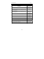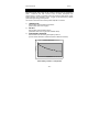
1
Instruction Manual
DO 6+ Dissolved Oxygen/Temp
68X243634
Rev 0 Mar 09
Technology Made Easy ...
Part of Thermo Fisher Scientific
Instruction Manual
DO 6+
Instruction Manual
DO 6+
Preface
This manual serves to explain the use of the DO 6+ hand held meter.
This manual functions in two ways: first as a step by step guide to help you
operate the meter; second, as a handy reference guide.
This manual is written to cover as many anticipated applications of the DO 6+
meter as possible. If there are doubts in the use of this meter, please do not
hesitate to contact the nearest Eutech Instruments Authorized Distributor.
Eutech Instruments will not accept any responsibility for damage or malfunction
to the meter caused by improper use of the instrument.
The information presented in this manual is subject to change without notice as
improvements are made, and does not represent a commitment on the part of
Eutech Instruments.
Copyright © 2009
Eutech Instruments Pte Ltd
All rights reserved.
Instruction Manual
DO 6+
Instruction Manual
DO 6+
Table of Contents
1. INTRODUCTION ...............................................................1
2. GETTING STARTED.........................................................2
2.1
2.2
2.3
2.4
2.5
2.6
2.7
2.8
2.9
Description of Keypad Functions ...................................................................2
Description of LCD Annunciators ...................................................................3
Inserting & removing the rubber armour / stand .............................................4
Inserting New Batteries.................................................................................4
Battery Replacement .....................................................................................5
Connecting the Electrode...............................................................................5
Electrode Information.....................................................................................6
Switching the Meter On .................................................................................7
Changing Mode .............................................................................................7
3. CALIBRATION..................................................................8
3.1
3.2
3.3
3.3.1
3.3.2
3.4
General Information .......................................................................................8
Temperature Calibration ................................................................................10
% Saturation Calibration ................................................................................11
100% Calibration ...............................................................................11
0% Calibration ...................................................................................12
mg/L or ppm Calibration ................................................................................13
4. MEASUREMENT ..............................................................14
4.1
4.2
4.3
4.4
Temperature Compensation ..........................................................................14
Taking Measurements ...................................................................................15
Pressure & Salinity Compensated Measurements .........................................16
Holding a Reading .........................................................................................16
5. SETUP...............................................................................17
5.1
5.2
5.3
5.4
5.5
5.6
5.7
5.8
5.9
Configuration Menu (COF.1)..........................................................................21
Automatic Temperature Compensation (A.ATC)............................................21
Selection of mg/L or ppm (b.DO) ...................................................................22
Calibration Data (CAL.2)................................................................................22
Electrode Data (ELE.3)..................................................................................23
Automatic Shut Off (AtO.4) ............................................................................24
Reset to Factory Default (rSt.5) .....................................................................25
% Saturation Offset Adjustment (OFS.6) .......................................................26
Pressure & Salinity Adjustment......................................................................27
6. PROBE MAINTENANCE ..................................................29
6.1
6.2
Cap and Electrolyte Replacement..................................................................30
Electrolyte Solution ........................................................................................31
7. TROUBLESHOOTING ......................................................31
8. ERROR MESSAGES ........................................................32
Instruction Manual
DO 6+
9. FACTORY DEFAULT SETTINGS ....................................33
10. SPECIFICATIONS ............................................................34
11. REPLACEMENTS AND ACCESSORIES.........................36
12. DISSOLVED OXYGEN THEORY .....................................37
Measurement Units.....................................................................................................38
What Is Being Measured?...........................................................................................38
Air Calibration .............................................................................................................39
Applications ................................................................................................................39
13. WARRANTY......................................................................40
14. RETURN OF ITEMS..........................................................40
Instruction Manual
DO 6+
1. INTRODUCTION
Thank you for purchasing the DO 6+. This microprocessor-based handheld
meter is economical and easy to use. It has a large custom LCD (Liquid Crystal
Display) for clear and easy reading.
The DO 6+ offers measurement of dissolved oxygen (DO) as percentage
saturation or concentration. Temperature measurement is also available in
degrees Celsius. The meter ensures accurate measurement of the dissolved
oxygen values through its temperature, barometric pressure and salinity
compensation features.
Meter kits include a dissolved oxygen probe, refill solution, a rubber armour /
stand, 4 alkaline “AAA” batteries, instruction manual, and warranty card. For
additional information, see Section 11 — REPLACEMENTS AND
ACCESSORIES.
Please read this manual thoroughly before operating your meter.
-1-
Instruction Manual
DO 6+
2. GETTING STARTED
2.1
Description of Keypad Functions
Your meter has 6 keys on its splash-proof keypad.
Some buttons have multiple functions depending
on the mode of operation.
ON/OFF Powers meter on and off. Meter starts
up in the measurement mode that you
last switched off from.
CAL
Enters into calibration mode. Pressing
while in calibration mode will abort
calibration without confirming value.
MODE
Selects desired measurement mode.
When pressed simultaneously with
ON/OFF, it will take you into the SETUP mode.
For more information see Section 5 — SETUP.
HOLD
Freezes measured reading. Press again to resume live reading.
ENTER
Confirms calibration value in calibration mode and confirm selections
in SETUP mode.
Increment/decrement values during calibration mode or scroll through
SETUP menus. Set offset adjustments and configuration settings.
-2-
Instruction Manual
2.2
DO 6+
Description of LCD Annunciators
Your meter has a large custom LCD that consists of 4-digit segments plus
annunciators for percentage saturation (%), concentration (mg/L or ppm) and
Temperature in degrees Celsius (T).
Other annunciators include “A” (when the ATC function is activated), “CAL”
(when meter is in calibration mode) and low battery condition.
Low Battery annunciator
Calibration Mode
Annunciator
CAL
Temperature Mode
TA
A T C annunciator
mg/l
milligram per litre
(Concentration Mode)
ppm
%
parts per million
Percentage
14-segment Liquid Crystal Display (Percentage Saturation
Mode)
Active LCD display for DO 6+
-3-
Instruction Manual
2.3
DO 6+
Inserting & removing the rubber armour / stand
1. To remove meter from rubber armour, push out from the bottom edges of
meter until it is completely out of boot. Ensure that your electrode cables
are not connected. See Figure 1.
2. To insert meter into armour, slide in from the top of meter before pushing
the bottom edges of meter down to set it into position. Lift up the stand at
the back of meter for bench top applications if necessary. See Figure 2.
Figure 1Ing New Batteries
Figure 2
2
2.4
Inserting New Batteries
The battery compartment is found at the back of instrument. To open the battery
compartment, push in the direction of arrow and lift up the cover. Note the
polarity of battery before inserting into position. After replacement, place cover
back and press down until it locks.
-4-
Instruction Manual
2.5
DO 6+
Battery Replacement
A low battery annunciator in the LCD alerts you when battery power is running
low. Caution: Power off the meter before replacing battery.
%
Low Battery Condition
2.6
Connecting the Electrode
1)
To connect the electrode, align the connector slots with the posts of
meter’s socket and rotate connector clockwise until it locks.
2)
To remove, rotate the connector in anti-clockwise direction until it
unlocks, and slide the connector off the socket.
3)
Insert the mini phono jack of temperature sensor into the socket on the
meter as shown below.
2.5 mm mini phono
for temperature
BNC connector
-5-
Instruction Manual
2.7
DO 6+
Electrode Information
The DO 6+ includes a galvanic DO electrode
(93X233912) which doesn’t require warm-up. It
generates a millivolt signal proportional to the
amount of oxygen in the solution.
The electrode has a dual cable; a BNC connector
for DO measurement and a phono jack plug for
temperature. The sensor utilizes a cathode,
anode, and electrolyte that are separated from
the sample by an oxygen permeable membrane.
The membrane is pre-assembled for you and
fixed to a detachable cap. The pre-assembled
cap design allows simple replacement and fast
conditioning.
The probe is light weight and includes a built-in
temperature sensor. The epoxy body of the probe
is 12mm diameter while the detachable Noryl cap
is 16mm diameter. The compact sensing area
reduces air entrapment resulting in quick,
accurate, and stable readings.
12 mm
Detachable
Pre-membraned Cap
(Probe Sensing Area)
The pre-assembled cap must be completely
submersed to obtain an accurate reading in
solutions. Provide simple stirring for best
results—ideally achieve a minimum water flow
rate of 2 inch/second on the membrane. The
probe is not recommended beyond 0 to 50 °C.
Shaking will aid to remove bubbles if needed
before taking a reading. When calibrating in air,
shake to remove water from the membrane.
The membrane is thin and can not be repaired if
damaged. Use care to protect from scratches,
abrasion, or contact with solids. For best results
keep membrane clean by rinsing after daily use.
See Section 6 – PROBE MAINTENANCE.
-6-
16 mm
Galvanic DO probe
(93X233912)
Instruction Manual
2.8
DO 6+
ON
OFF
Switching the Meter On
CAL 13 CAL 24
Press ON/OFF to power up your meter. Your meter will
cycle through various setup parameters when switched on.
1)
All LCD segments will briefly illuminate.
2)
The model [DO 6+] will display next along with mg/l,
ppm, and % annunciators.
3)
Next, the meter revision number [r #.##] is shown
briefly before beginning measurement.
4)
The meter begins with the measurement mode that
was in use when it was previously powered off⎯%,
mg/l, ppm, or T.
2.9
TAvg
mg/l
NTU
ppm
%pH
mg/l
ppm
%
A
%
Changing Mode
Press MODE to switch between percentage saturation (%), concentration
(mg/L)(ppm), and temperature (T) measurement.
A
Automatic Temperature
Compensation
%
Percentage Saturation
MODE
A
mg/l
Concentration Mode
MODE
Temperature Mode
TA
MODE
-7-
Instruction Manual
DO 6+
3. CALIBRATION
3.1
General Information
The DO 6+ has three measurement modes; DO as % saturation, DO as mg/L
(or ppm) concentration, and temperature.
Dissolved oxygen levels vary with temperature, barometric pressure, and
salinity, so calibration must be performed with consideration of these factors. It
is necessary to set the proper temperature, barometric pressure and
salinity values prior to performing any DO calibration or measurement.
See Section 3.2 — Temperature Calibration
See Section 5.2 — Automatic Temperature Compensation.
See Section 5.9 — Pressure & Salinity Adjustment.
The DO 6+ will accept two % saturation calibration points; 100% using
saturated air or air-saturated water, and 0% using zero oxygen solution. When
100% calibration is performed, the corresponding concentration is adjusted
simultaneously. Therefore, it is not necessary to calibrate the concentration
mode. If calibrating for 0% oxygen, note that the meter will take several minutes
to reach 0% saturation value and constant stirring is not required.
The following table lists calibration values in % saturation calibration mode with
two different barometric pressures. Note that the saturation value (92.1%) has
decreased due to the lower barometric pressure entered.
% Saturation (per
factory default value)
Calibration Value
(760mmHg)
Calibration Value
(700mmHg)
less than 10%
0%
0%
10.1% to 49.9%
Err.1 (error 1)
Err.1 (error 1)
50% to 200%
100%
92.1%
If calibration is attempted from 10.1% to 49.9%, the “Err.1” message is shown—
calibration is rejected and the display will return to measurement mode.
-8-
Instruction Manual
DO 6+
The DO 6+ will accept one calibration point in concentration mode. The
minimum value is 2 mg/L (ppm), and the calibration window is +/- 40% of the
factory default value.
Temperature and % saturation calibration should take place before attempting
to perform mg/L (ppm) concentration calibration.
Calibration of the concentration mode will only replace the previous
concentration calibration and does not affect the % saturation calibration.
To offset your % saturation reading to match another instrument, see Section
5.8 — % Saturation Offset Adjustment.
New calibration values will automatically override the existing data. Perform
daily calibration for best results. To completely recalibrate the meter and when
installing a replacement electrode, it is best to clear all calibration data. See
Section 5.7Reset to Factory Default.
-9-
Instruction Manual
3.2
DO 6+
TA
Temperature Calibration
For best DO accuracy, ensure that the
temperature is accurate. The temperature
sensor of the DO 6+ probe has been
factory calibrated, however if it changes
over time or if the probe is replaced,
calibration may be necessary. To protect
from erroneous calibrations, the allowable
tolerance is limited to ±5°C adjustment of
the factory default value.
Most users utilize automatic temperature
compensation using the sensor that is built
into the probe. However, manual
temperature compensation can be used to
input a fixed, known temperature.
1)
Press MODE to select temperature
mode. The display should show “T”
for temperature and “A” for automatic
temperature compensation.
2)
Dip the probe into a solution with a
known, accurate temperature (i.e. a
temperature bath). Allow enough time
for the temperature reading to
stabilize.
CAL
TA
CAL
Factory default
Temperature
Measurement
TA
CAL
HOLD
ENTER
“CO” will display for
1.5 seconds
TA
3)
Press CAL. The CAL indicator will
blink above the display. The
temperature value shown is the value based on the factory default.
4)
Press ▲ ▼ to adjust the reading to match the correct temperature value
(i.e. of the temperature bath).
5)
Press HOLD/ENTER to confirm the calibration and return to measurement
mode.
Press CAL as needed to exit calibration without confirmation at any time.
- 10 -
Instruction Manual
3.3
DO 6+
% Saturation Calibration
The DO6+ can be easily calibrated in air. For best DO accuracy, ensure that the
barometric pressure value is accurate.
The barometric pressure factory default is
760 mm Hg, which results in a theoretical
calibration value of 100% saturation in air.
If the barometric pressure setting has been
changed from 760 mm Hg, the meter will
automatically adjust to a new % saturation
calibration value instead of 100%. This new
value is correct for the adjusted barometric
pressure.
3.3.1
A
%
CAL
CAL
%
100% Calibration
1)
Rinse the probe well with DI water or
rinse solution.
2)
Press MODE to select % saturation.
3)
Hold the probe in the air with the tip
facing downwards. Wait for the
reading to stabilize.
4)
Press CAL. The CAL indicator and
intended percentage calibration point
(100%) display briefly, before CAL
flashes. The % value based on the
factory default calibration is shown.
5)
Press HOLD/ENTER to confirm the
calibration. The meter displays “CO”,
automatically calibrates to 100.0% air
saturation,
then
returns
to
measurement mode.
- 11 -
Calibration point will be
displayed for 1.5 seconds
CAL
%
HOLD
ENTER
A value with respect to the
factory default calibration
will be displayed
“CO” will displayed for
1.5 seconds
A
%
Instruction Manual
3.3.2
DO 6+
0% Calibration
1)
Rinse the probe well with DI water or
rinse solution.
2)
Press MODE to select % saturation.
3)
Dip the probe into zero oxygen
solution. Wait for the reading to
stabilize.
4)
5)
A
%
CAL
CAL
Press CAL. The CAL indicator and
intended percentage calibration point
(0%) display briefly, before CAL
flashes. The % value based on the
factory default calibration is shown.
Press HOLD/ENTER to confirm the
calibration. The meter displays “CO”,
automatically calibrates to 0.0%
saturation,
then
returns
to
measurement mode.
%
Calibration point will be
displayed for 1.5 seconds
CAL
%
HOLD
ENTER
A value with respect to the
factory default calibration
will be displayed
“CO” will displayed for
1.5 seconds
A
%
- 12 -
Instruction Manual
3.4
DO 6+
mg/L or ppm Calibration
A
mg/l
Performing a 100% saturation calibration will
simultaneously calibrate the corresponding
mg/L (ppm) concentration value. Therefore,
additional mg/L (ppm) calibration isn’t
required in most circumstances.
If desired, you can perform a calibration
adjustment in mg/L (ppm) without affecting
your % saturation calibration value.
1)
Perform 100% saturation calibration.
See Section 3.3.1 — 100% Calibration.
2)
Rinse the probe well with DI water or
rinse solution.
3)
Dip the probe into a sample of known
oxygen concentration (i.e. determined
by titration or another instrument). Wait
for the reading to stabilize.
4)
Press MODE to select the mg/L (ppm).
5)
Press CAL. The CAL indicator and
current concentration display briefly,
before CAL flashes. The concentration
value based on the factory default
calibration is shown.
CAL
CAL
mg/l
A value with respect to the
factory default calibration
will be displayed
CAL
mg/l
HOLD
ENTER
“CO” will display
for 1.5 seconds
A
mg/l
6)
Press ▲ ▼ to adjust the reading to
match the known oxygen concentration
value.
7)
Press HOLD/ENTER to confirm the
calibration. The meter displays “CO”, automatically calibrates to the
entered value, then returns to measurement mode.
NOTE: The minimum calibration value is 2 mg/L. To prevent erroneous
calibrations, the calibration is limited to ±40% adjustment of the factory default
value.
- 13 -
Instruction Manual
DO 6+
4. MEASUREMENT
The DO 6+ offers automatic or manual temperature
See Section 5.2 — Automatic Temperature Compensation.
compensation.
A
Automatic Temperature
Compensation activated
%
4.1
Temperature Compensation
Insert the phono plug of the probe for Automatic Temperature Compensation
(ATC). The “A” annunciator will display normally when active, or blink if the
phono plug is disconnected.
T
Deactivate “A.ATC” for manual temperature
compensation. The “A” annunciator is not
displayed when the meter is in manual
temperature compensation mode.
For manual temperature compensation, manually
enter the desired process temperature into the
meter from 0 and 50 °C. Default is 25 °C.
1)
Press MODE to select temperature.
2)
Press CAL. The “CAL” indicator will start
blinking and the display will show the last
manually set temperature value.
3)
Check the temperature of your sample using
an accurate reference thermometer. Wait for
the value to stabilize. Press ▲ ▼ to manually
set the temperature value.
4)
Press HOLD/ENTER to confirm the
calibration. The meter displays “CO”,
automatically sets the entered value, then
returns to measurement mode.
- 14 -
CAL
CAL
T
Last set manual
temperature setting
CAL
T
HOLD
ENTER
“CO” will display for 1.5
seconds
T
Instruction Manual
4.2
DO 6+
Taking Measurements
Follow these general rules when taking measurements: keep the membrane
free from contact with solid objects, provide stirring of your solution⎯this helps
to overcome the oxygen consumption of the probe and prevents air bubble
entrapment, do not strike against hard surfaces, and do not submerge the cable
for extended periods.
1)
Rinse the probe well with DI water or
rinse solution.
2)
Select the appropriate measurement
mode. Press MODE to toggle
between modes:
a. Percentage Saturation (%)
A
%
MODE
A
b. Concentration (mg/L) or (ppm)
mg/l
c. Temperature (T)
3)
Dip the probe into the sample.
4)
Allow reading to stabilize and observe
reading.
To change the concentration units see
Section 5.3—Selection of mg/L or ppm.
- 15 -
MODE
TA
Instruction Manual
4.3
DO 6+
Pressure & Salinity Compensated Measurements
During measurement the dissolved oxygen reading is automatically
compensated for salinity and pressure based on values entered in the setup
menu. For best DO accuracy, ensure pressure and salinity are adjusted
accordingly from the setup menu. The factory default values are 760 mm Hg
(101.3 kPa) barometric pressure (sea level) and 0.0 ppt salinity (no salinity).
See Section 5.9 — Pressure & Salinity Adjustment.
4.4
Holding a Reading
To hold the displayed reading momentarily, press HOLD/ENTER during any
measurement. The %, mg/L, ppm or T annunciator will blink, indicating that the
value is held.
A
%
Annunciator Blinks when
meter is in “HOLD” mode
Press HOLD/ENTER again to deactivate the HOLD function. The meter reverts
to the current active measurement and the annunciator will stop blinking.
If the auto-off feature is activated, the meter will turn off automatically after 20
minutes of non use The HOLD value is not retained when the meter is shut off
automatically or manually.
- 16 -
Instruction Manual
DO 6+
5. SETUP
There are two setup menus. One menu is derived from the % saturation and
temperature modes, the other menu is derived from the mg/L (or ppm)
concentration mode.
1)
Press MODE to display % or temperature. Press ON/OFF to power off.
OR
Press MODE to display mg/L (or ppm). Press ON/OFF to power off.
2)
With the meter off, keep the MODE key pressed. Press and release
ON/OFF, then release MODE. The meter should display “SEt.P” after
ON/OFF is released and “COF.1” after MODE is released.
Press CAL one or more times as needed during setup mode to exit and return
to measurement mode at any time.
- 17 -
Instruction Manual
DO 6+
Setup Menu
Configuration Menu
A.ATC Automatic Temperature Compensation
b.DO Select mg/L or ppm units for concentration mode
(available from concentration setup only)
View the latest calibration data according to the respective setup
menu.
View the electrode properties
FACT View the slope factor
OFS View the % saturation offset adjustment.
(available from % saturation concentration setup only)
HI.mV View the mV value at 100% saturation
LO.mV View the mV value at 0% saturation
Selection of automatic power-off (20 min from the last key press)
Reset Menu
A.CAL Calibration only reset to factory default
b.USR User settings reset to factory default
% saturation offset adjustment
(available from % saturation concentration setup only)
Dissolved Oxygen Parameters
A.HG Barometric pressure adjustment in mmHg
A.PA Barometric pressure adjustment in kilopascal
b.SAL Salinity adjustment
(available from concentration setup only)
- 18 -
Instruction Manual
MODE
ON
OFF
DO 6+
Switch off from % Saturation
or Temperature measurement
mode. Press and hold MODE
key and then switch on.
SEt.P will display for
1 second
% or Temperature Setup Menu
- 19 -
Instruction Manual
MODE
ON
OFF
DO 6+
Switch off from Concentration
measurement mode. Press
and hold MODE key and then
switch on.
SEt.P will display for
1 second
mg/L (ppm) Concentration Setup Menu
- 20 -
Instruction Manual
DO 6+
5.1
Configuration Menu (COF.1)
5.2
Automatic Temperature Compensation (A.ATC)
Use this menu to change automatic temperature compensation (A) or units of
concentration (mg/L or ppm). ATC is recommended for most applications.
1)
From “COF.1” of either setup menu, press
HOLD/ENTER to display “A.ATC”.
2)
Press HOLD/ENTER to enter the selection
menu.
3)
Use ▲▼ to select YES (activate ATC) or NO
(deactivate ATC and activate manual
temperature compensation).
4)
Press HOLD/ENTER to confirm.
5)
Press CAL to return to measurement mode.
HOLD
ENTER
HOLD
ENTER
Selection of Automatic or
Manual Temperature
Compensation
- 21 -
Instruction Manual
5.3
1)
DO 6+
Selection of mg/L or ppm (b.DO)
From “COF.1” of the mg/L (ppm) setup
menu, press HOLD/ENTER three times to
display “b.DO”.
2)
Use ▲▼ to select the desired units of
measurement.
3)
Press HOLD/ENTER to confirm.
4)
Press CAL to return to measurement mode.
5.4
mg/l
ppm
Calibration Data (CAL.2)
To view the % saturation or mg/L (ppm) concentration calibration data, proceed
from the corresponding setup menu.
1)
From the setup menu, press ▲▼ to select
“CAL.2” for the most recent calibration data.
2)
Press HOLD/ENTER to view calibration data.
3)
Press HOLD/ENTER or CAL to exit.
4)
Press CAL to return to measurement mode.
Note: “ -- -- -- -- ” indicates no calibration data exists
for the selected mode.
HOLD
ENTER
CAL
%
Display will show the latest % saturation
calibration if set up menu is selected from the
DO % Saturation Mode
CAL
mg/l
Display will show the latest mg/l or ppm
calibration if set up menu is selected from the
DO mg/l (ppm) Concentration Mode
- 22 -
Instruction Manual
5.5
DO 6+
Electrode Data (ELE.3)
Use this menu to view electrode data for diagnostic purposes. Data includes;
slope factor (FACT), % saturation offset (OFS), 100% saturation mV value
(HI.mV), and 0% saturation mV value (LO.mV). To view electrode data for %
saturation or mg/L (ppm) modes, enter from the corresponding setup menu.
The electrode slope factor gives an indication of the probe’s efficiency. It is the
ratio of the actual mV produced by the probe to the theoretical mV value. The
ratio displays from 0.5 to 1.999.
The % saturation offset allows you to view the electrode offset adjustment made
in Section 5.8 — % Saturation Offset Adjustment.
1)
From the setup menu, press ▲▼ to select “ELE.3”.
2)
Press HOLD/ENTER to enter the menu. “FACT” is momentarily shown
before displaying the slope factor.
3)
Press HOLD/ENTER again. “OFS” is momentarily shown before displaying
% saturation offset. Note: this is not available from the mg/L (ppm)
concentration setup menu.
4)
Press HOLD/ENTER again. “HI.mV” is momentarily shown before
displaying the electrodes mV output at 100%.
5)
Press HOLD/ENTER again. “LO.mV” is momentarily shown before
displaying the electrodes mV output at 0%.
Press CAL to exit the setup mode and return to measurement mode at any
time.
- 23 -
Instruction Manual
DO 6+
HOLD
ENT ER
“FACT” displays for
1.5 seconds
Viewing of the offset
percentage adjustment will be
available only if set up menu is
selected from the DO %
Saturation or the Temperature
Mode. Otherwise, this menu
will be skipped.
“OFS” displays for
1.5 seconds
HOLD
ENT ER
%
“HI.mV” displays
for 1.5 seconds
HOLD
ENT ER
HOLD
ENT ER
“LO.mV” displays
for 1.5 seconds
5.6
Automatic Shut Off (AtO.4)
Use this feature to conserve batteries. When active, the
meter will automatically shut off 20 minutes after the last
key press.
1)
From the setup menu, press ▲▼ to select “AtO.4”.
2)
Press HOLD/ENTER to enter the menu.
3)
Use ▲▼ to select YES (activate automatic off) or
NO (activate automatic off).
4)
Press HOLD/ENTER to confirm.
5)
Press CAL to return to measurement mode.
- 24 -
HOLD
ENTER
Instruction Manual
5.7
DO 6+
Reset to Factory Default (rSt.5)
Use this mode to reset the meter to factory default settings. There are two
levels of reset.
Calibration (A.CAL) resets calibration values only.
User (b.USR) resets all data, calibration, and other customized setup functions.
1)
From the setup menu, press ▲▼ to select
“rSt.5”.
2)
Press HOLD/ENTER to enter the menu.
3)
Press HOLD/ENTER to enter calibration reset
“A.CAL”.
4)
Use ▲▼ to select YES (reset calibration) or NO
(do not reset calibration).
HOLD
ENTER
HOLD
ENTER
5)
Press HOLD/ENTER to confirm. If “YES”, the
meter returns to measurement mode after
resetting.
Note: Both % and concentration calibrations are
reset when from the % saturation setup.
However, when calibration reset occurs from
the concentration setup, only concentration is
reset.
6)
If “NO”, the User Reset menu “b.USR” is
displayed.
7)
Press HOLD/ENTER to enter the menu.
8)
Use ▲▼ to select YES (reset user) or NO (do not reset user).
9)
Press HOLD/ENTER to confirm.
Calibration
Reset
10) If “YES”, the meter returns to measurement mode after resetting.
11) Press CAL to return to measurement mode.
- 25 -
Instruction Manual
5.8
DO 6+
% Saturation Offset Adjustment (OFS.6)
Use this feature to offset the meter’s value
when cross referenced to another DO
meter. The DO 6+ allows +/- 10.0% offset
adjustment. View the offset value from the
Electrode Data menu “ELE.3”.
1)
2)
HOLD
ENTER
Using the % saturation mode of your
DO6+, observe the reading a sample
solution after it has stabilized.
%
Measured reading based on last
percentage saturation calibration
is displayed momentarily
Similarly, observe the reading of the
same sample using another DO meter
as a reference. The probe of the
reference meter should be immersed
in the same sample at the same depth.
3)
Switch off the DO6+ and enter the %
saturation setup menu.
4)
Press ▲▼ to select “OFS.6”.
5)
Press HOLD/ENTER to enter the
menu. The display will momentarily
show the measured reading based on
the last calibration before displaying
the last offset adjusted value.
6)
Use ▲▼ to enter the value of the
reference DO meter.
%
Last offset adjusted
value will be displayed
%
HOLD
ENTER
“CO” will display for
1.5 seconds
Display will return to “OFS.6” subgroup menu
7)
Press HOLD/ENTER to confirm.
8)
Press CAL to return to measurement mode.
Note: User calibrations will reset the offset adjustment to 0.0 %.
- 26 -
Instruction Manual
5.9
DO 6+
Pressure & Salinity Adjustment
Use this menu to set barometric pressure and salinity values of the sample to
be measured. Use mmHg (A.HG) or kilopascal (A.PA) barometric pressure
units, and ppt salinity units (bSAL) from concentration setup menu. For best
accuracy, enter the actual salinity value if your samples are at least 0.1 ppt (100
ppm). Maximum adjustment is 50 ppt (50,000 ppm or 5% salt).
1)
Press MODE to display mg/L concentration. Press ON/OFF to power off.
2)
With the meter off, keep the MODE key pressed. Press and release
ON/OFF, then release MODE. The meter should display “SEt.P” after
ON/OFF is released and “COF.1” after MODE is released.
3)
Press ▲▼ until the display shows “DPr.7”.
4)
Press HOLD/ENTER. The display will show the current setting, either
“A.HG” (millimeters of mercury or mm Hg) or “A.PA” (kilopascal or kPa).
5)
Use ▲▼ to select the desired barometric pressure units, then press
HOLD/ENTER to confirm.
6)
Use ▲▼ to set the actual pressure value and press HOLD/ENTER to
confirm. If values were changed, the confirmation indicator “CO” will
display briefly.
7)
Next, “b.SAL” (salinity adjustment) will display. “DPr.7” (main group menu)
will display if mg/L was not used in step 1). Note: if the concentration setup
was not used in step 1) the meter will return to “DPr.7” as salinity is only
accessable thru concentration setup.
8)
Press CAL to return to measurement mode or HOLD/ENTER for salinity
setting adjustment.
9)
Use ▲▼ to enter the salinity of your solution in parts per thousand (ppt).
10) Press HOLD/ENTER to confirm. If values were changed, a confirmation
indicator “CO” will display briefly.
11) Press CAL to return to measurement mode.
- 27 -
Instruction Manual
DO 6+
HOLD
ENTER
HOLD
ENTER
HOLD
ENTER
HOLD
ENTER
HOLD
ENTER
HOLD
ENTER
“CO” will display
for 1.5 seconds
Display will continue to
Salinity setting menu
“b.SAL” if Set Up menu is
entered from mg/l (ppm)
mode. Otherwise display will
return back to “DPr.7”
HOLD
ENTER
“CO” will display
for 1.5 seconds
Display will continue to
“CO” will display for
Salinity setting menu
1.5 seconds
“b.SAL” if Set Up menu is
entered from mg/l (ppm)
Display will return back to “DPr.7”
mode. Otherwise display will
subgroup menu
return back to “DPr.7”
Pressure & Salinity Adjustment Sequences
- 28 -
Instruction Manual
DO 6+
6. PROBE MAINTENANCE
The DO 6+ probe is a galvanic measuring element which produces an output
proportional to the oxygen present in the medium in which it is placed. The
galvanic probe design lets you take measurements immediately – without the
typical 15 minute wait of polargraphic dissolved oxygen probes.
The probe consists of two parts. The upper part consists of the anode, cathode,
and dual cable. The lower part consists of a pre-assembled cap, and electrolyte
solution.
Oxygen diffuses through the membrane onto the cathode, where it is
consumed. This process produces an electrical current which flows through the
cable to the meter. The electric current produced is proportional to the oxygen
that passes through the membrane and the layer of electrolyte. This makes it
possible to measure the partial pressure of oxygen in the sample at a given
temperature.
Since the DO in the sample is consumed by the cathode it is essential to have
flow past the membrane of the probe to prevent the occurrence of false
readings. The probe uses very little oxygen for its measurement. This enables it
to function correctly with liquid movement as low as 2 inch/sec across
membrane.
The permeability of the membrane to oxygen varies greatly with temperature.
Therefore compensation is needed for this variation. The DO 6+ probe comes
with built-in temperature compensation for the membrane variation.
Proper maintenance will help you maximize probe life and accurate readings.
Deposits on the membrane surface act as a barrier to oxygen diffusing through
the membrane, so clean the membrane to assure maximum reliability.
After each use, rinse the probe with clean water to avoid any hardening of
deposits. If growth develops on the probe, use a disinfecting chemical to clean.
NOTE: Although the membrane is strong and not easily damaged, wipe it gently
while cleaning it. If the membrane is punctured, damaged, or torn, the probe will
not function properly.
There are no special probe storage requirements.
- 29 -
Instruction Manual
6.1
DO 6+
Cap and Electrolyte Replacement
Replacement of the pre-assembled cap is required only when you cannot
calibrate the probe, or if the membrane is damaged. Typical membrane
damages are punctures or wrinkles caused during measurements or cleaning.
For part numbers, see Section 11 – REPLACEMENTS AND ACCESSORIES.
1)
Unscrew the cap counter clockwise from the probe sensing tip.
2)
Rinse the probe under running water.
3)
Mount the nozzle tip onto the syringe provided. Fill the syringe with the
refill solution through the tip of the plastic bottle.
4)
Hold the probe upside down. Insert the nozzle tip into one of the 4 holes
surrounding the silver cathode. Inject the fill solution into the probe body
until solution leaks out from the fill hole (approximately 5 mL).
5)
Replace pre-assembled cap by tightening clockwise until hand tightened.
6)
Allow at least 1 hour for the electrode to equilibrate before usage.
1
4
2
3
5
6
- 30 -
Instruction Manual
6.2
DO 6+
Electrolyte Solution
The electrolyte solution in your probe’s cap will deplete on usage and will need
to be replaced periodically. The replacement electrolyte solution included with
your probe comes premixed and ready to use. To order more electrolyte
solution, Section 11 – REPLACEMENTS AND ACCESSORIES.
7. TROUBLESHOOTING
Problem
Cause
Solution
No display
when
turned on
a)
Batteries not in place
a)
b)
Batteries not in correct
polarity (+ / – position)
Ensure batteries are in place and
making good contact
b)
Re-insert batteries with correct
polarity
c)
Replace batteries
Unstable
readings
c)
Weak batteries
a)
Insufficient electrolyte in
probe
a)
Fill probe with electrolyte & / or
replace pre-assembled cap
b)
Air bubbles trapped around
the probe
b)
Stir or tap probe to remove
bubbles
c)
Dirty or damaged probe
c)
d)
Probe not deep enough in
sample
Clean the probe and recalibrate
d)
e)
External noise pickup or
induction caused by
nearby electric motor
Make sure sample entirely
covers the probe sensors
e)
Move or switch off interfering
motor
Broken probe
f)
Replace probe
f)
Slow
response
a)
Dirty / Oily probe
a)
Clean probe
b)
Temperature is changing
b)
Allow temperature to stabilize
No
response
to key
press
a)
HOLD in use- indicated
by flashing display
a)
Press HOLD/ENTER
b)
Return to dealer
c)
Reset by reinserting batteries
b)
Damaged pad
c)
Internal program error
- 31 -
Instruction Manual
DO 6+
8. ERROR MESSAGES
LCD Display
Indicates
Cause
Solution
Low battery
Need new batteries or
battery connection is
bad.
Clean battery contacts.
Replace batteries,
noting polarity.
“Err 1” in %
Saturation
Mode
% Saturation
calibration
error
Calibration is attempted
when the factory
calibrated absolute
value is within
10.1% to 49.9%
Check the value of the
calibration solution. If
zero calibration is done,
make sure the limit of
10% is not exceeded
Recondition your probe
“Err. 1” in mg/L
(ppm)
Concentration
Mode
Concentration
calibration
error
Calibration is attempted
when the factory
calibrated absolute
value is below 2.00
Verify the solution is
above 2.00
Verify the temperature
and salinity settings
Recondition your probe
“UR”/”OR” with
blinking “A”
annunciator in
Temperature
Mode
ATC probe
error,
Under Range,
Over Range
ATC probe is
disconnected or broken
with the ATC feature
activated.
Temperature is out of
range
Connect the ATC plug
to the meter. Verify the
temperature accuracy.
Ensure probe is not
broken or punctured.
“----“with
blinking “A”
annunciator in
% Saturation
and
Concentration
Mode
ATC probe
error
ATC probe is
disconnected or broken
with the ATC feature
activated.
Temperature is out of
range
Connect the ATC plug
to the meter. Verify the
temperature accuracy.
Ensure probe is not
broken or punctured.
- 32 -
Instruction Manual
DO 6+
9. FACTORY DEFAULT SETTINGS
MENU
DESCRIPTION
COF.1
Configuration Setup Menu
A.ATC
Automatic Temperature Compensation
OPTIONS
DEFAULT
YES / NO
YES
b.DO
DO Concentration Units
mg/L or ppm
mg/L
CAL.2
Calibration Data
View only
____
ELE.3
Electrode Data Menu
FACT
Electrode Slope Factor
View only
1.000
OFS
Viewing the % Saturation offset
adjustment.
View only
0.0%
HI.mV
View mV Value at 100% Saturation
View only
50 mV
LO.mV
View mV Value at 0% Saturation
View only
0 mV
AtO.4
Automatic Power Off
YES / NO
YES
rSt.5
Reset to Factory Default Menu
A.CAL
Selection of Calibration Reset
NO / YES
NO
b.USR
Selection of User Reset
NO / YES
NO
OFS.6
% Saturation Offset Adjustment
+/- 10.0%
0.0%
DPr.7
Dissolved Oxygen Parameters Menu
A.HG
Pressure Adjustment in mm Hg
500 – 1499
760
A.PA
Pressure Adjustment in kPa
66.6 - 199.9
101.3
Salinity Adjustment in ppt
0.0 - 50.0
0.0
Manual Temperature Compensation
0.0 - 50.0 °C
25.0°C
b.SAL
- 33 -
Instruction Manual
DO 6+
10. SPECIFICATIONS
% Saturation Mode
Range
Resolution
Relative accuracy
0.00 – 200.0 %
0.1 %
± 1.5% of Full Scale
mg/L (ppm) Concentration Mode
Range
Resolution
Relative accuracy
0.00 – 20.00 mg/L or ppm
0.01 mg/L; 0.01 ppm
± 1.5% of Full Scale
Temperature
Range
Resolution
Relative accuracy
-5.0 – 105.0 °C (meter only)*
0.1 °C
± 0.5 °C
*Probe measures 0.0 – 50.0 °C
Salinity Correction
Range
Resolution
Method
0.0 – 50.0 ppt
0.1 ppt
Automatic correction after manual input
Barometric Pressure Correction (mm Hg)
Range
Resolution
Method
500 to 1499 mm Hg or 66.6 to 199.9 kPA
1 mm Hg or 0.1 kPA
Automatic correction after manual input
Automatic Temperature Compensation
0.0 to 50.0°C
Manual Temperature Compensation
0.0 to 50.0°C
Probe (DO / Temp)
Galvanic / Thermistor
Probe Diameter
Body 12 mm, Cap 16 mm
Response Time
60 seconds to achieve 95% of the reading
% Saturation Calibration Points
100% in saturated air or air-saturated
water.
0% in zero oxygen solution
- 34 -
Instruction Manual
DO 6+
% Saturation Calibration Limits
Factory calibrated absolute value of 10.0%
and below for 0% point & 50% to 200% for
100% point.
Concentration Calibration Window
+/- 40% from the factory default
measurement value. Minimum reading
allowed is 2.00 mg/L (ppm).
Temperature Calibration Window
+/- 5°C from factory default measurement
Offset Adjustments (% Saturation)
+/- 10.0 of reading in Saturation mode
HOLD function
Yes
Auto-Off function
Selectable Auto Off function. (20 minutes
after last press)
Display
Custom Single 4 Digit LCD
Inputs
BNC for DO & 2.5 mm Phono for
temperature
Operating Range
0 to 50 °C
Power Requirements
4 AAA-sized batteries (included)
Battery Life
> 700 hours (Alkaline Batteries)
Dimensions
Meter: 15.7 x 8.5 x 4.2 cm / 255 g
Probe: 115 mm x 12 mm (Dia), 3-ft cable
Membrane housing: 16 mm (Dia)
- 35 -
Instruction Manual
DO 6+
11. REPLACEMENTS AND ACCESSORIES
Order Code
Part Number
Description
DO 6+ Dissolved Oxygen Meter in Hard Plastic Carry Case
ECDO600PLUSK
01X370112
DO 6+ Dissolved Oxygen Meter with 3 m Cable Electrode, (2)
Assembled Membrane Cap Housing, Refilling Electrolyte (10mL) & Carrying Kit Set
ECDO602PLUSK
01X370113
DO 6+ Dissolved Oxygen Meter with 1 m Cable Electrode, 2
Assembled Membrane Cap Housing, Refilling Electrolyte (10mL) & Carrying Kit Set
ECDO601PLUSK
01X370114
DO probe, 10-mL electrolyte and plastic syringe, 3 m Cable
ECDO6HANDY3M
01X233916
DO probe, 10 mL electrolyte and plastic syringe, 1 m Cable
ECDO6HANDY
01X233913
Hard Plastic Carry Case with (4) sample Bottles (60 mL)
ECECODRYKIT
01X266903
Replacement Rubber Armour / Stand
15X410401
Assembled Membrane Cap
01X241608
Assembled Membrane Cap, 10-mL electrolyte, plastic syringe
01X241609
DO probe electrolyte refilling solution
01X211226 (50 mL)
Replacement Alkaline AAA batteries
60X023200
- 36 -
Instruction Manual
DO 6+
12. DISSOLVED OXYGEN THEORY
Dissolved Oxygen (DO) refers to the volume of oxygen that is contained in
water. There are two main sources of DO in water; atmosphere and
photosynthesis. Waves and tumbling water mix air into the water where oxygen
readily dissolves until saturation occurs. Oxygen is also produced by aquatic
plants and algae during photosynthesis.
The amount of DO that can be held by water depends on 3 factors:
1)
TEMPERATURE:
DO increases with decreasing temperature
(colder water holds more oxygen)
2)
SALINITY:
DO increases with decreasing salinity
(freshwater holds more oxygen than saltwater does)
3)
ATMOSPHERIC PRESSURE:
DO decreases with decreasing atmospheric pressure
(amount of DO absorbed in water decreases as altitude increases)
Solubility of oxygen in water contact with water saturated air at
standard atmospheric pressure
16
14
Solubility mg/L
12
10
8
6
4
2
0
0
5
10
15
20
25
30
35
40
45
50
Temperature °C
DO Solubility in Water vs Temperature
- 37 -
Instruction Manual
DO 6+
Measurement Units
One measure of DO in water is parts per million (ppm) which is the number of
oxygen molecules (O2) per million total molecules in a sample. Calculating the
% Saturation is another way to analyze DO levels. % Saturation is the
measured DO level divided by the greatest amount of oxygen that the water
could hold under various temperature and atmospheric pressure conditions
multiplied by 100.
What Is Being Measured?
DO probes respond to the partial pressure of oxygen in liquid or gas being
measured – they measure the “pressure” of oxygen rather than concentration.
All of the oxygen entering the probe is consumed at the cathode where it is
electrochemically reduced to hydroxyl ions producing an electrical current within
the probe:
-
O2 + 2 H2O + 4 e Æ 4 OH
–
Since all oxygen entering the probe is chemically consumed, the partial
pressure of oxygen in the electrolyte is zero. Therefore, a partial pressure
gradient exists across the membrane and the rate at which oxygen enters the
probe is a function of the partial pressure of oxygen in the gas or in liquid being
measured.
When a probe is placed in air saturated water, the current it produces will not be
affected by the temperature or salinity of the water. The DO concentration in
the water, however, will vary with temperature and salinity. Because it is
convenient to report DO concentration in mg/L or ppm, it is necessary to adjust
for temperature and salinity of the water to get correct readings in these units.
If DO were to be reported in terms of partial pressure or % Saturation, then
temperature and/or salinity compensation for oxygen solubility would not be
necessary. Most probes are temperature compensated – i.e. they convert the
“partial pressure measurement” to mg/L of DO at whatever temperature the
water happens to be at for a given salinity and barometric pressure.
- 38 -
Instruction Manual
DO 6+
Air Calibration
Understanding the principle of air calibration is easy, once you know that it is
partial pressure that the probe is responding to. When the probe is in air, it is
measuring the partial pressure of oxygen in air. If water is air saturated, then
the partial pressure of oxygen in the water will be the same as it is in air.
Therefore, all you need to know is the temperature of the air in which the probe
is placed. By consulting solubility tables for oxygen at the particular barometric
pressure and salinity of the water being measured, the corresponding
concentration (mg/L or ppm) can be found for air saturated water at the air
calibration temperature, and the meter can be set accordingly. Because most
meters are temperature compensated, they will still give correct readings in
mg/L even though the actual water temperature may be different to the air
calibration temperature. Note: The closer the air calibration temperature is to
the water temperature, the more accurate the calibration.
Applications
Oxygen is essential for fish, invertebrate, plant, and aerobic bacteria respiration.
DO levels below 3 ppm are stressful to most aquatic organisms. Levels below 2
or 1 ppm will not support fish. Fish growth and activity usually require 5 to 6
ppm of DO, an important consideration for Aqua-culture industry.
Low DO indicates a demand on the oxygen of the system. Natural organic
material such as leaves accumulate in the stream and create an oxygen
demand as it is decomposed. Organic materials from human activities also
create an oxygen demand in the system. Micro-organisms consume oxygen as
they decompose sewage, urban and agricultural run-off, and discharge from
food-processing plants, meat-packing plants and diaries. There is an optimum
DO level for this process and if DO level falls too low, the micro-organisms die
and the decomposition ceases. If DO level is too high, more power is used than
necessary for aeration and the process becomes costly.
In boiler water application, presence of oxygen in the water will increase
corrosion and helps build up boiler scale that inhibits heat transfer. In such
instance it is critical to keep DO concentration to a minimum.
Some pollutants such as acid mine drainage produce direct chemical demands
on oxygen in the water. DO is consumed in the oxidation-reduction reactions of
- 39 -
Instruction Manual
DO 6+
1-
1+
introduced chemical compounds such as nitrate (NO3 ) and ammonia (NH4 ),
22+
+
sulfate (SO4 ), and sulfite (SO3 ) and ferrous (Fe2 ) and ferric (Fe3 ) ions.
These are important consideration for water and wastewater treatment industry.
13. WARRANTY
This meter is supplied with a three-year warranty, six-month warranty for
electrode against significant deviations in material and workmanship.
If repair or adjustment is necessary and has not been the result of abuse or
misuse within the designated period, please return – freight pre-paid – and
correction will be made without charge. Eutech Instruments will determine if the
product problem is due to deviations or customer misuse.
Out of warranty products will be repaired on a charged basis.
Exclusions
The warranty on your instrument shall not apply to defects resulting from:
•
Improper or inadequate maintenance by customer
•
Unauthorized modification or misuse
•
Operation outside of the environment specifications of the products
14. RETURN OF ITEMS
Authorization must be obtained from our Customer Service Department or
authorized distributor before returning items for any reason. A “Return Goods
Authorization” (RGA) form is available through our Authorized Distributor.
Please include data regarding the reason the items are to be returned. For your
protection, items must be carefully packed to prevent damage in shipment and
insured against possible damage or loss. Eutech Instruments will not be
responsible for damage resulting from careless or insufficient packing. A
restocking charge will be made on all unauthorized returns.
Eutech Instruments Pte Ltd reserve the right to make improvements in
design, construction, and appearance of products without notice.
- 40 -
For more information on Eutech Instruments products, contact your
nearest distributor or visit our website listed below:
Eutech Instruments Pte Ltd.
Blk 55, Ayer Rajah Crescent,
#04-16/24 Singapore 139949
Tel: (65) 6778 6876
Fax: (65) 6773 0836
E-mail: [email protected]
Web-site: www.eutechinst.com
Distributed by: