1
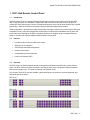
DENSITÉ series
RCP-10x0 Remote Control Panel
Guide to Installation and Operation
M823-9900-100
17 Apr 2007
Miranda
Technologies Inc.
3499 Douglas-B.-Floreani
St-Laurent, Québec, Canada H4S 1Y6
Tel. 514-333-1772
Fax. 514-333-9828
www.miranda.com
© 2007 Miranda Technologies Inc..
GUIDE TO INSTALLATION AND OPERATION
Safety Compliance Information
Safety Compliance
This equipment complies with:
-
CSA C22.2 No. 60950-1-03 / Safety of Information Technology Equipment, Including Electrical Business Equipment.
UL 60950-1 (1st Edition) / Safety of Information Technology Equipment, Including Electrical Business Equipment.
st
IEC 60950-1 (1 Edition) / Safety of Information Technology Equipment, Including Electrical Business Equipment.
CAUTION
These servicing instructions are for use by qualified service personnel only. To reduce the risk of electric shock, do not
perform any servicing other than that contained in the operating instructions unless you are qualified to do so. Refer all
servicing to qualified service personnel. Servicing should be done in a static-free environment.
Electromagnetic Compatibility
-
This equipment has been tested for verification of compliance with FCC Part 15, Subpart B, class A requirements for
Digital Devices.
This equipment complies with the requirements of:
EN 55022 Class A, Electromagnetic Emissions,
EN 61000-3-2 & -3-3, Disturbance in Supply Systems
EN 61000-4-2, -3, -4, -5, -6, -8 & -11 Electromagnetic Immunity
How to contact us:
For technical assistance, please contact the Miranda Technical support centre nearest you:
Americas
Telephone:
+1-800-224-7882
e-mail:
[email protected]
Asia
Telephone:
+81-3-5730-2987
e-mail:
[email protected]
Visit our web site at www.miranda.com
RCP-10x0
Europe, Middle East,
Africa, UK
Telephone:
+44 (0) 1491 820222
e-mail:
[email protected]
France (only)
Telephone:
+33 (0) 1 55 86 87 88
e-mail:
[email protected]
GUIDE TO INSTALLATION AND OPERATION
Table of Contents
1
RCP-10x0 Remote Control Panel ..............................................................................................1
1.1
1.2
1.3
2
Installation ..................................................................................................................................3
2.1
2.2
2.3
2.4
3
3.3
3.4
3.5
3.6
3.7
Operating Modes................................................................................................................................. 4
Network considerations....................................................................................................................... 5
3.2.1 Network traffic overload ......................................................................................................... 6
Response to a Connection Failure...................................................................................................... 6
Configure the RCP-10x0 using the IP Interface.................................................................................. 6
3.4.1 Panel Mode ............................................................................................................................ 7
3.4.2 Ethernet Interface................................................................................................................... 8
3.4.3 Densité Chassis ..................................................................................................................... 8
3.4.4 Appearance............................................................................................................................ 9
3.4.5 Disabled buttons .................................................................................................................... 9
3.4.6 Factory Values ..................................................................................................................... 10
3.4.7 Apply .................................................................................................................................... 10
Upgrade the RCP-10x0..................................................................................................................... 11
Review the event log for the RCP-10x0............................................................................................ 11
Button Labels .................................................................................................................................... 12
Operation ..................................................................................................................................13
4.1
4.2
4.3
4.4
4.5
4.6
4.7
5
Unpacking ........................................................................................................................................... 3
Installation ........................................................................................................................................... 3
Connection .......................................................................................................................................... 3
PoE Power Supply .............................................................................................................................. 3
Configuration ..............................................................................................................................4
3.1
3.2
4
Introduction ......................................................................................................................................... 1
Features .............................................................................................................................................. 1
Overview ............................................................................................................................................. 1
Operating Modes............................................................................................................................... 14
4.1.1 XY without preset mode....................................................................................................... 14
4.1.2 XY- with preset mode........................................................................................................... 14
4.1.3 Single Bus mode .................................................................................................................. 14
4.1.4 Dual Bus mode..................................................................................................................... 14
4.1.5 Quad Bus Mode ................................................................................................................... 14
Label strip illumination:...................................................................................................................... 15
Configuration persistency.................................................................................................................. 15
Source buttons .................................................................................................................................. 15
Destination buttons (XY modes) ....................................................................................................... 16
Function buttons................................................................................................................................ 16
4.6.1 PANEL ENABLE button ....................................................................................................... 17
4.6.2 TAKE Button ........................................................................................................................ 18
4.6.3 LOCK button ........................................................................................................................ 19
4.6.4 PROTECT button ................................................................................................................. 20
Dual and Quad Bus Operation.......................................................................................................... 20
Troubleshooting Guide ............................................................................................................22
5.1
Initial setup ........................................................................................................................................ 22
RCP-10x0
GUIDE TO INSTALLATION AND OPERATION
5.2
5.3
5.4
6
Panel configuration ............................................................................................................................24
Testing the connection to the HRS-1801… .......................................................................................26
5.3.1 …when using fixed IP parameters........................................................................................26
5.3.2 …when using DHCP.............................................................................................................26
Troubleshooting .................................................................................................................................27
Specifications........................................................................................................................... 29
RCP-10x0
GUIDE TO INSTALLATION AND OPERATION
1 RCP-10x0 Remote Control Panel
1.1
Introduction
The RCP-10x0 is a series of panels providing fast and easy operator remote control of the Densité HRS1801 routing switchers. It is available in multiple sizes and can control routers with sizes up to 40x4. All
models offer easy and ergonomic control via backlit push-buttons, which can be easily labeled using a backlit
legend strip. Labels for the strip can be printed using a template provided with the product.
Panel configuration is provided via a simple user-friendly web page, hosted in every control panel, and easily
accessible from any computer equipped with an Ethernet port. Advanced functionalities such as locks and
protects are fully supported by the RCP-10x0 panels and power is supplied using a compatible Ethernet
switch, or a Power over ethernet adapter supplied with the control panel.
1.2
1.3
Features
•
Provides control for Densité HRS-1801 routers
•
Single bus or XY operation
•
User-friendly web-based configuration
•
Preset or direct mode
•
Configurable locks and protections
•
Power over Ethernet (PoE)
Overview
The RCP-10x0 is an Ethernet-based remote control panel for Miranda’s new HRS-1801 routing switcher
series. The RCP-10x0 control panel connects to the Densite frame via a 10/100 BaseT Ethernet network,
and controls a single router. The panel is powered over Ethernet (PoE).
Four versions of the RCP-10x0 are available, named according to the number of sources supported, and
with panel layouts as shown:
RCP-1010
RCP-1020
RCP-1030
RCP-10x0 | 1
GUIDE TO INSTALLATION AND OPERATION
RCP-1040
In these diagrams, the upper and lower rows of elements are pushbuttons, while the center row represents
LED backlights for an inserted label strip.
•
All pushbuttons are unlabelled, and the client should insert a label strip to properly identify them in
the current operating configuration.
The RCP-10x0 can be set to OPERATE mode or CONFIG mode using a rear-panel DIP switch
2 | RCP-10x0
GUIDE TO INSTALLATION AND OPERATION
2 Installation
2.1
Unpacking
The following items should be included in the RCP-10x0 package:
•
•
•
•
•
•
•
•
2.2
RCP-10x0 control panel
User manual
Power over Ethernet adapter (to inject power to the RCP-10x0 via the ethernet port)
Power cord
Ethernet cross cable to help with configuration (when in CONFIG mode)
A straight ethernet cable for standard operation
Clear lexan (to protect an eventual paper strip or the identification lexan)
Identification lexan (identifies the leftmost function buttons and allows users to write on it using a
marker to identify the sources and destinations)
Installation
Install the RCP-10x0 in a standard 19” rack frame using four mounting screws (not supplied)
•
2.3
The RCP-10x0 occupies 1 RU in height
Connection
The RCP-10x0 communicates with a router through an IP connection. The unit also receives its power
through the same connector (PoE). Connection of the RCP-10x0 is therefore a simple, one-step process:
•
•
Connect the RCP-10x0 to a 10/100 BaseT Ethernet network, using a connecting cable that supplies
power using the PoE protocol (compliant with IEEE 802.3af). See section 2.4 for information about
the power source.
The controlled router must be installed in a Densité frame that is accessible from the same LAN
The RCP-10x0 is delivered from the factory with the following default settings
Default IP address
Default Subnet Mask
Default Gateway
DHCP
Default DENSITE Frame IP address
2.4
192.168.100.100
255.255.255.0
192.168.100.1
Disabled
192.168.100.101
PoE Power Supply
PoE (Power over Ethernet) technology supplies DC power for the device over conductors in the ethernet
cable. The power can be inserted on the data conductors, or on spare conductors in the cable. The RCP10x0 supports both options. Two sources of power are possible.
•
Power-sourcing ethernet switch: the power is supplied to the cable directly at the ethernet switch
•
Power injector: the cable from a standard, non-power-sourcing ethernet switch plugs into a power
injector, whose output combines the input signals with power.
IEEE 802.3af specifies a nominal 48 volt supply, and the system specification includes provision for detection
by the power sourcing equipment that the powered device is PoE-compatible.
RCP-10x0 | 3
GUIDE TO INSTALLATION AND OPERATION
3 Configuration
The RCP-10x0 remote control panel is configured with the use of an on-board web server.
Access to the web server requires the user to enter the RCP-10x0’s IP address in the browser’s address
window. This IP address will vary with the current operating mode of the RCP-10x0.
3.1
Operating Modes
The RCP-10x0 can be placed in one of two modes, using rear-panel DIP switches. The web server
configuration pages are available in both modes, but the modes differ in several respects:
•
Configuration mode – the web interface has a fixed IP address and the panel cannot be used to
control a router.
•
Operation mode – the panel can be used to operate a router. The web interface IP address may be
variable, and a system log of information, warning and errors is maintained as a troubleshooting tool.
See section 4 for information about the OPERATION mode, and instructions for operating the
RCP-10x0.
A bank of 4 DIP switches is accessible on the back panel.
ON
1
2
Switch
3
4
Description
Function
SW1
Operation/Config
OPERATION panel is in normal operation mode
CONFIG: panel is in configuration mode
SW2
Router/Client
ROUTER: operate an HRS-1801 Densité router
CLIENT: (future use)
SW3
Spare
SW4
Spare
In order to configure the router, the user must access its web server using a browser.
•
•
In CONFIG mode, the router’s IP address is fixed to a factory-defined value
In OPERATION mode, the IP address may be fixed or dynamic, and the fixed address is usersettable
Exiting the factory, the panel will be in CONFIG mode with the following IP parameters.
4 | RCP-10x0
GUIDE TO INSTALLATION AND OPERATION
Factory Default IP parameters
Configuration
Mode
(fixed)
Operation
Mode
(configurable)
IP address
192.168.100.100
Subnet mask
255.255.255.0
Gateway
192.168.100.1
DHCP
Disabled
IP address
192.168.100.100
Subnet mask
255.255.255.0
Gateway
192.168.100.1
DHCP
Disabled
To restore factory defaults and all IP parameters to the values given in the table:
•
•
3.2
Push and hold the reset button for at least 10 seconds.
The reset button is recessed into the rear panel beside the DIP switches
Network considerations
The control panel controls Miranda HRS-1801 routers through its Ethernet connection. It supports 10BaseT
and 100BaseT in half or full duplex. The Ethernet negotiation is completely automatic and there is no way to
manually force a speed and duplex mode. However, forcing the Ethernet switch on the other end to a
specific speed and duplex setting will be reported as the preferred way to communicate on the link and this
setting should be used.
A single control panel can communicate with a single router in one frame.
The panel supports the following protocols:
o
o
o
TCP (Berkeley style sockets)
DHCP client
HTTP server
The TCP protocol is used to connect to a remote Densité frame. The panel connects as a client to the frame
using a TCP/IP socket.
•
If connecting to a DENSITE-CPU-ETH controller, the user must make sure that no one else is
connected to the Densité frame, or the panel will not be able to use it (since only one connection is
available at a time on this type of controller)
•
If connecting to a DENSITE-CPU-ETH2 controller, there is no restriction as this controller supports
multiple connections. You can then use multiple panels or controlling devices (such as iControl or
RCP-100) at the same time to control the router
The DHCP client can be enabled or disabled using the web interface. If the panel is configured to use DHCP,
it will acquire its IP parameters from the DHCP server at boot up and on lease expiration.
•
If a DHCP server cannot be found, the panel will default to the fixed IP parameters set for operation
mode.
RCP-10x0 | 5
GUIDE TO INSTALLATION AND OPERATION
Several network configuration options are available to IT personal to automate the process of finding the
panel in the network. The DHCP server could be configured to always assign the same IP parameters to the
panel by matching a MAC address to a specific IP address. Also, the DNS server could have a static entry
resolving a panel name to the IP address.
A web server, described in detail in Section 3.4 below, allows the user to configure the panel. However, this
web server does not act as a panel control point. To change cross points using the panel, the user must be
in front of it, pressing buttons. The panel does not receive control commands from its Ethernet port.
The panel does not permit daisy chaining or slave/master configuration.
3.2.1
Network traffic overload
When the RCP-10x0 is connected to a network that sends a lot of broadcast packets that are not directed to
the RCP-10x0, the panel might not be able to handle the unnecessary large network load. This could cause
communication discontinuity between the controller and the panel.
•
3.3
To lower the network load on the RCP-10x0, you can use dedicated network segments or create
virtual LANs to offload the traffic received by the panel. Consult your IT specialist if necessary.
Response to a Connection Failure
When the panel is initializing, all button actions are ignored and all LEDs are off except for the PANEL
ENABLE button that will be slowly flashing green to identify initialization sequence.
Once the panel has acquired its IP parameters, it will load its configuration parameters from non-volatile
memory and begin its work. It will first establish a connection to the frame, check the slot where the router to
control is, determine how to control the router and initialize its status tables to determine each source’s state.
If something fails during initialization, the panel enters a timed loop to retry the initialization sequence
indefinitely until it gets to a point where it can communicate with the router. When a general error of this sort
happens, the user can connect to the web server of the panel and get more information on what is
happening. The panel will maintain a small system log in non-volatile memory that is available to the user.
The panel will not be available until it has been able to communicate with the router. The user will know
something is wrong if the panel never comes up.
When the panel is already running and its connection is lost to the router, it will go back to its power-up
sequence (flashing PANEL ENABLE, all buttons off).
3.4
Configure the RCP-10x0 using the IP Interface
The RCP-10x0 can be configured while it is set to either CONFIG mode or OPERATE mode. The only
practical differences between the two are:
IP address:
•
•
In CONFIG mode, the IP address of the Router is fixed (see the table above)
In OPERATE mode, the IP address may be difficult to determine, especially if DHCP is enabled
6 | RCP-10x0
GUIDE TO INSTALLATION AND OPERATION
Functionality:
•
•
In CONFIG mode, the panel cannot be used to operate a
router
In OPERATE mode, the panel is functional and can control a
router
Enter the IP address of the router in your browser’s Address window to
open the web page generated by the RCP-10x0’s on-board web
server.
Click on the Setup tab to open the configuration window.
The window is shown on the right, and includes a number of distinct
sections, which will be discussed individually
3.4.1
Panel Mode
Select the panel operating mode using the Panel Mode pulldown.
The available options are shown in the table below, and will be discussed in detail in section 4.
RCP-1010
RCP-1020
RCP-1030
RCP-1040
Single Bus
Single Bus
Single Bus
Single Bus
XY – Without Preset
Dual 10x1 Bus
XY – Without Preset
Dual 20x1 bus
XY – With Preset
XY – Without Preset
XY – With Preset
Quad 10x1 bus
XY – With Preset
XY – Without Preset
XY – With Preset
RCP-10x0 | 7
GUIDE TO INSTALLATION AND OPERATION
Bus number (1-4) – enter the following data, depending on the mode selected in the pulldown
•
Single bus mode – the number of the bus that is to be controlled
•
Dual bus mode – enter the number of the first bus to be controlled (possible values 1, 2 or 3)
o
•
3.4.2
the RCP-10x0 will control that bus and the next one
The default value is 1
Ethernet Interface
Select the IP addressing mode using the pulldown.
The available choices are:
•
DHCP
use dynamic network addressing. When selected, it allows a server to dynamically attribute an IP
address and configuration information to the RCP-10x0. Normally the DHCP server provides at least
the following basic information: IP address, subnet mask and default gateway. When "DHCP" is
chosen, the fixed network parameters are not used unless a DHCP server cannot be found. DNS
servers are usually also reported by the DHCP server (2 are reported but only the primary server is
displayed in the web page)
•
Fixed
forces the RCP-10x0 to use the attributes entered in the Fixed IP Mode data boxes. The user should
consult the network manager if unfamiliar with the requirements for this data.
o Enter data for the four listed Fixed IP Mode network parameters
The MAC address is a unique identifier for this specific device, and is not user-configurable.
3.4.3
Densité Chassis
Enter the information that identifies the router that the RCP-10x0 will control.
8 | RCP-10x0
GUIDE TO INSTALLATION AND OPERATION
You must enter:
•
•
•
•
3.4.4
The IP address of the Densité frame in which the router is installed
The slot number of the router output card in that frame
The control panel ID
o Enter a unique number to identify this control panel (range 1-250)
The first source to control (pulldown listing all available sources)
o If the control panel is able to control fewer sources than are attached to the router, select
which source is the first to control
o For example, an RCP-1020 is operating a 40-input router. The RCP will control 20 consecutive
sources beginning with the number entered, so if 18 is entered, the control panel will operate
the router as if it is a 20-input router with sources 18 to 37 as its inputs
o In Dual or Quad bus mode, this identifies the first source in the controlled range (see sect.4.7)
Appearance
Use the three pulldowns to select the brightness of the LEDs that illuminate the control panel buttons and the
slide-in label strip between the rows of pushbuttons.
Choices are:
•
•
•
HIGH intensity
LOW intensity
LEGEND intensity
- set the level of brightness that corresponds to High intensity in operation
- set the level of brightness that corresponds to Low intensity in operation
- set the level of illumination for the slide-in label strip (see Section 3.7)
All three pulldowns allow the level to be set from 0% to 100% in steps of 5%
3.4.5
Disabled buttons
Click in the box for any control panel button to disable it
•
•
The button will be OFF and non-functional when disabled
This only affects the RCP-10x0; the router itself is not affected
RCP-10x0 | 9
GUIDE TO INSTALLATION AND OPERATION
Click the Clear All button to empty all the checkboxes
3.4.6
Factory Values
Click the Factory Values button to restore all settings on this panel to a set of factory-defined values
3.4.7
Apply
Click the Apply button when the contents of this panel have been set to the desired values. The RCP-10x0
will be rebooted, and will resume operation with the modified settings. The Results screen will be shown
while the panel is rebooting.
Note that if you have enabled DHCP during this change, the panel’s IP address will be set by the DHCP
server, and the default values will no longer apply. See the note on the Results page as shown above.
10 | RCP-10x0
GUIDE TO INSTALLATION AND OPERATION
The same comment applies if you have modified the IP address. The webpage will not automatically bring
you back to the setup page. You will have to enter the IP address in the address bar of Internet Explorer.
3.5
Upgrade the RCP-10x0
Enter the IP address of the router in your browser’s Address window to open the web page generated by the
RCP-10x0’s on-board web server, and click on the Upgrade tab.
Specify the upgrade file:
•
•
If you know its coordinates, enter them in the data box
If you don’t know the coordinates, click the browse button and find the file by navigating in the
Choose File window
Once the file location has been entered, click Upgrade, and follow the on-screen instructions.
NOTE – it is very important to:
•
•
press on Upgrade once
wait for at least 4 minutes before doing anything else.
Instructions on the screen will provide more information but this is a MUST DO.
3.6
Review the event log for the RCP-10x0
Enter the IP address of the router in your browser’s Address window to open the web page generated by the
RCP-10x0’s on-board web server, and click on the Log tab.
You will see a listing of all recent events, which may be of use when troubleshooting.
RCP-10x0 | 11
GUIDE TO INSTALLATION AND OPERATION
3.7
Button Labels
All control panel buttons on the RCP-10x0 are unlabelled.
•
•
A space is left for a label strip between the two rows of buttons, and slots are provided to slide a strip
of labels into place.
Each button is provided with a dedicated LED to illuminate its label space
The RCP-10x0 is shipped with several items related to button labels:
•
•
A white plastic strip of the correct size, with the function button labels (see Section 4.6) printed on
the plastic, that could be written on with a marker to label the buttons
A clear plastic strip pf the correct size that will protect the above strip or a paper strip.
A template for printing paper label strips is available from Miranda.
12 | RCP-10x0
GUIDE TO INSTALLATION AND OPERATION
4 Operation
The operations supported by the RCP-10x0 panel are straightforward in nature, but vary with the operational
configuration,
•
To operate the RCP-10x0, make sure the rear panel CONFIG/OPERATION DIP switch is in the
OPERATION position
To switch an output to a different source:
Select the output bus to be switched using the Destination buttons (XY mode only).
•
•
Only one destination at a time can be selected
Not required in the single bus, dual bus or quad bus mode
If the Preset mode is OFF (TAKE button is OFF):
•
•
Push the Source button for the source to be routed to the selected output
The output will be switched immediately
If Preset Mode is ON (Take button is ON and dim – available in XY with Preset mode only)
•
•
•
Push the Source button for the source to be routed to the selected output
New source button and TAKE buttons flash at high intensity
Push the TAKE button to switch the output
o If TAKE is not pushed within 30 seconds, the new source selection is cancelled
See section 4.7 for a description of the panel button assignments in Dual and Quad Bus modes.
When the user selects a crosspoint that is inhibited, the panel will report the failure to engage the crosspoint
on the source button (see source button description in Section 4.4). There is no way to inhibit or uninhibit a
crosspoint from the panel; the user must use iControl or the front panel of the router to do this.
The functionality of the control panel buttons varies, depending on the operating mode.
•
A detailed chart of the status/functionality reporting of each button is given in sections 4.4 to 4.6.
The status and functionality of the various buttons is reported by:
•
•
•
•
•
Color
(Red, Green, Amber)
Intensity
(Off, Low, High)
Flash rate
(None, Slow, Fast).
If a button is not used in a given configuration, the button’s backlight is off.
The color, intensity and flashing properties of a given button are not configurable.
Note: If you are connected to a Densité frame with a DENSITE-CPU-ETH2 controller, other users may
connect to the same frame and operate the router at the same time.
•
If you notice the button display changing when you have done nothing, it is probably another user
who has made the changes
RCP-10x0 | 13
GUIDE TO INSTALLATION AND OPERATION
4.1
Operating Modes
The panel may be configured in any of the following operating modes:
RCP-1010
RCP-1020
RCP-1030
RCP-1040
Single Bus
Single Bus
Single Bus
Single Bus
XY – Without Preset
Dual 10x1 Bus
XY – Without Preset
Dual 20x1 bus
XY – With Preset
XY – Without Preset
XY – With Preset
Quad 10x1 bus
XY – With Preset
XY – Without Preset
XY – With Preset
4.1.1
•
•
4.1.2
•
•
•
4.1.3
•
•
4.1.4
•
•
•
•
•
•
4.1.5
•
•
XY without preset mode
Operates as an Nx4 router, with N being the number of sources supported (e.g. RCP-1020 supports
20 sources)
Select the destination, then push the source button to activate the crosspoint
XY- with preset mode
Operates as an Nx4 router, with N being the number of sources supported (e.g. RCP-1040 supports
40 sources)
Select the destination, then push the source button to preset a switch
Push TAKE to activate the crosspoint
Single Bus mode
The destination bus is pre-selected in the configuration and the panel operates only that bus on the
router
Push the source button to activate the crosspoint
Dual Bus mode
The panel is configured to control two consecutive destination buses on the router (e.g. 1 & 2, 2 & 3
or 3 & 4)
The upper row of source buttons is assigned to the first controlled bus
The lower row of source buttons is assigned to the second controlled bus
The source buttons are assigned to M consecutive sources, where M is the scale of the Dual Bus
mode (e.g. 20x1 can control 20 consecutive sources)
The first controlled source is specified in the configuration.
Push the source button to activate the crosspoint
Quad Bus Mode
The panel is configured to control all four output busses of the router (only available with RCP-1040)
The panel source buttons are assigned to the buses in groups of 10, each being half of the upper or
lower row
14 | RCP-10x0
GUIDE TO INSTALLATION AND OPERATION
•
•
4.2
The source buttons are assigned to 10 consecutive sources, beginning with a source that is specified
in the configuration
Push the source button to activate the crosspoint
Label strip illumination:
The label for each active button is backlit by a white LED
•
•
The label illumination for an inactive button is OFF
The intensity of all active label illumination LEDs is the same, and is set in the Setup tab of the
configuration web page (see section 3.4.4)
4.3 Configuration persistency
All configuration parameters are saved in non-volatile memory. Upon a power failure, brownout or reset, the
saved configuration parameters are reloaded. If the DIP switch is changed while the power is on, the panel
will switch to the appropriate mode immediately.
4.4 Source buttons
The source selection buttons control N consecutive sources, where N is the number of source buttons
available on the panel.
Green
Colors
Red
Amber
Any
SOURCE
button
Intensities
Flashing
If the Clean Switch option is available AND activated on the
HRS-1801, green means that the signal is within the timing
window to perform a clean switch.
No signal is present at this position
If the Clean Switch option is available AND activated on the
HRS-1801, amber means that the signal is outside the timing
window to perform a clean switch.
Off
Button is not used in the current configuration
Low
The source is not selected for the bus (single, dual or quad bus
mode) or the selected destination (XY modes)
High
This source is routed to the output bus (single, dual or quad
bus mode) or to the selected destination (XY modes)
None
Normal operation
Slow
The source is preset for a pending take (XY modes)
Fast
The user asked for a cross point that cannot be activated
(may be inhibited, locked, etc.).
RCP-10x0 | 15
GUIDE TO INSTALLATION AND OPERATION
4.5 Destination buttons (XY modes)
In XY mode, the destination buttons are positioned as pictured here (numbers are for reference only, they
are not printed on the buttons).
1
2
3
4
Destination #1 corresponds to output #1 on the router and so forth.
Green
Colors
Red
This button is always amber.
Amber
Any
DEST
Button
(XY mode
only)
Intensities
Flashing
Off
Panel is in single, dual or quad bus mode, this button is
unused, or panel is disabled.
Low
The specific destination is not selected for review
High
The specific destination is selected for review
None
Normal operation
Slow
Unused
Fast
Unused
In Single Bus mode, the button for the selected bus will be on at HIGH intensity, and the others will be OFF
In Dual Bus mode, the four destination buttons will be OFF
In Quad Bus mode, the four destination buttons will be OFF
4.6 Function buttons
The function buttons are positioned as pictured here (numbers refer to the descriptive text here; they are not
printed on the buttons).
16 | RCP-10x0
GUIDE TO INSTALLATION AND OPERATION
1
2
3
4
4.6.1
1.
2.
3.
4.
PANEL ENABLE
DESTINATION (or BUS) LOCK
TAKE
DESTINATION (or BUS) PROTECT
PANEL ENABLE button
The PANEL ENABLE button has three primary functions:
1. To correctly disconnect the RCP-10x0 from the Densité controller in the frame containing the router
:
• To disable and disconnect the RCP-10x0 from the router, push and hold the PANEL ENABLE button
for 5 seconds while the panel is enabled. This will properly disconnect the panel from the Densité
controller. The ethernet cable can then be unplugged from the RCP-10x0
•
Failure to do so when disconnecting a panel from a DENSITE-CPU-ETH could lead the controller in
thinking the connection to the panel is still valid. This would render the only connection on this
controller unusable and require a reset of the controller.
2. The Panel Enable button is used to temporarily disable the other control panel buttons, protecting
against accidental crosspoint selections. The status of the inputs is still shown by the source buttons.
3. The button is used to announce that the panel is initializing.
•
When the panel is initializing, all button actions are ignored and all LEDs are off except for the
PANEL ENABLE button, which is slowly flashing.
Green
Colors
Red
This button is always amber.
Amber
PANEL
ENABLE
button
Intensities
Flashing
Off
The panel is unpowered.
Low
Panel is disabled.
• If source buttons are dimmed low, their colors represent
the state of the specific source.
• If the source buttons are off, the panel is disabled AND
properly disconnected from the Densité controller and the
HRS-1801.
All other buttons are off.
High
The panel is enabled and initialized.
None
Normal operation
Slow
The panel is initializing. If this button is always flashing,
check the error log on the web interface.
Fast
If the panel is disabled and any other button is pressed, this
button flashes for 1 second.
RCP-10x0 | 17
GUIDE TO INSTALLATION AND OPERATION
4.6.2
TAKE Button
The TAKE button has two applications:
1. PRESET – TAKE
When the panel is in XY-With Preset mode, selecting a destination and a new source will NOT
activate the crosspoint. Instead:
• The new source button and the TAKE button will flash together
• Pushing the TAKE button will activate the crosspoint
• The pending TAKE will time-out after 30 seconds, and the TAKE and source buttons will
stop flashing
2. Salvo Firing
When the RCP-10x0 is in any state except {XY With Preset and a pending TAKE}, the TAKE button
is used to enable the Salvo Firing mode.
The HRS-1801 can be programmed with up to 10 Salvos (i.e. presets). These salvos cannot be set
from the RCP-10x0, but they can be fired.
•
Push and hold the TAKE button, and all buttons except the rightmost ten buttons in the top
row of source buttons, plus the ENABLE and TAKE buttons, will be extinguished.
The ten source buttons will be amber at low intensity
The ten source buttons control the ten Salvos, counting from left to right.
Push the appropriate source button to fire the salvo
Release the TAKE button to view the normal button display
•
•
•
•
Note that if you disable the TAKE button in the Setup panel, and place the RCP-10x0 in XY with Preset
mode, the panel will function as a Read-only panel
• The source buttons will display the crosspoint status by color, and show which is selected for each
destination by intensity, but the crosspoints cannot be activated by pushing the buttons.
Green
Colors
Red
This button is always amber.
Amber
TAKE
button
Intensities
Flashing
18 | RCP-10x0
Off
The panel is in XY-without preset, single, dual or quad bus
mode, button is unused or panel is disabled.
Low
Panel is in XY –With Preset mode. Selecting a source only
presets this source.
High
A TAKE operation is pending. If the take operation is not
completed after a 30 second timeout, the preset will be
cleared and intensity of this button will return to LOW.
None
Normal operation
Slow
A TAKE operation is pending. Used with “High”
Fast
Unused
GUIDE TO INSTALLATION AND OPERATION
4.6.3
LOCK button
The LOCK button freezes the status of a router output bus:
• Single bus mode – the output bus is frozen
• Dual and Quad bus mode – LOCK is not used
• XY mode – the selected destination is frozen
When a bus/destination is locked, its source selection cannot be changed.
When a LOCK has been established, the LOCK button intensity will be HIGH
• Single bus mode – always
• XY mode – when a locked destination is selected
Green
Colors
Red
This button is always amber.
Amber
LOCK
button
Off
The panel is unpowered or the LOCK button was disabled on
the web configuration page.
Low
The bus (single bus mode) or selected destination (XY mode)
is NOT locked
High
The bus (single bus mode) or the selected destination (XY
mode) is locked. Pressing the lock button will unlock the bus
or the selected destination unless it was locked by another
panel. Pressing and holding the LOCK button for 5 seconds
will force it to unlock.
None
Normal operation
Slow
Unused
Fast
User tried to change a source when the bus or destination
was locked or attempted to unlock the bus or a destination
locked by another panel.
Intensities
Flashing
The LOCK is applied to the router itself, not to the RCP-10x0. Since multiple control panels can have
simultaneous control of the router, an output bus or destination can be locked from any panel. The LOCK
button will indicate the lock on all panels connected to the router.
To UNLOCK a locked destination, push the LOCK button while it is indicating the lock (i.e. high intensity).
• If the LOCK was initiated at this panel, the destination will be unlocked
• If the LOCK was initiated at another panel, the LOCK button will flash but remain bright, and the
LOCK will remain in effect
To UNLOCK a destination that was locked from another panel:
• Push and hold the LOCK button for 5 seconds
• This may be necessary if the panel that initiated the lock is no longer connected to the router.
The LOCK button flashes in two situations:
1. When the user attempts to change the source selection on a locked bus/destination
• LOCK button is BRIGHT because a LOCK is in place
• Both the LOCK button and the SOURCE button flash
2. When the user attempts to select an inhibited crosspoint for the selected destination.
• LOCK button is DIM, but flashes BRIGHT
RCP-10x0 | 19
GUIDE TO INSTALLATION AND OPERATION
•
Both the LOCK button and the SOURCE button flash
Crosspoints can only be inhibited at the router, and not through the use of the RCP-10x0 control panel.
4.6.4
PROTECT button
The PROTECT button behaves similarly to the LOCK button except:
• A PROTECTED output is still controllable from this panel
• To other users, the protected output will behave exactly as if it has been LOCKED by another panel:
o The LOCK button will be BRIGHT, and will flash if an attempt is made to change the source
o It can be overridden just like a locked output, by holding the LOCK button for 5 seconds.
Green
Colors
Red
This button is always amber.
Amber
PROTECT
button
Intensities
Flashing
4.7
Off
The panel is unpowered or the PROTECT button was disabled
on the web configuration page.
Low
The bus (single bus mode) or the selected destination (XY
mode) is NOT protected. Other panels can change cross
points.
High
The bus (single bus mode) or the selected destination (XY
mode) is protected. Only this panel can change cross points
for this bus or destination.
None
Normal operation
Slow
Unused
Fast
Unused
Dual and Quad Bus Operation
The following diagrams illustrate the button and bus assignments when the panel is operated in Dual and
Quad Bus modes. In each case:
•
Bus number is the bus selected in the Panel Mode section of the configuration panel
(see Section 3.4.1)
•
First Source to control is the Source # selected in the Densité Chassis section of the configuration
panel (see section 3.4.3)
20 | RCP-10x0
GUIDE TO INSTALLATION AND OPERATION
RCP-1020 – Dual 10x1
First source to control
First source to control + 10
Bus number
Bus number + 1
First source to control
First source to control + 10
RCP-1040 – Dual 20x1
First source to control
First source to control + 20
Bus number
Bus number + 1
First source to control
First source to control + 20
RCP-1040 – Quad 10x1
First source to control
First source to control + 10
Bus 1
First source to control
First source to control + 10
Bus 2
Bus 3
Bus 4
First source to control
First source to control + 10
First source to control
First source to control + 10
RCP-10x0 | 21
GUIDE TO INSTALLATION AND OPERATION
5 Troubleshooting Guide
Here is what to do when you have a problem communicating between an HRS-1801 and an RCP-10x0.
Please follow ALL the steps in order.
5.1
Initial setup
1. Connect the RCP-10x0 as depicted below:
Computer
AC
PoE Power
Injector
IN
OUT
IP parameters of this computer:
IP Address : 192.168.100.200
Subnet mask : 255.255.255.0
Gateway : 192.168.100.1
CROSSOVER Ethernet cable
Straight Ethernet cable
DIP Switch settings:
CONFIG mode
ROUTER mode
Make sure the Ethernet cable between the PoE Power Injector and the computer is a crossover cable.
2. Set the IP parameters of the computer as follow (Windows XP shown):
22 | RCP-10x0
GUIDE TO INSTALLATION AND OPERATION
3. Set the DIP Switches on the panel to match the following image:
ON
1
2
3
4
4. Push the reset button of the panel using a paper clip.
5. Look at the “LINK/ACTIVITY” LED under the Ethernet connector
• it should be green and it might flash amber once in a while
6. Look at the LINK LED on the computer (usually located just beside the Ethernet connector). It should be
indicating a good link (green on most computers).
RCP-10x0 | 23
GUIDE TO INSTALLATION AND OPERATION
5.2
Panel configuration
1. From the computer, open a console (Start – Programs – Accessories – Command Prompt)
and type “arp –d”:
This clears the ARP table and makes sure no MAC address is linked to the IP address of the panel.
2. Open Internet Explorer on the PC and type “http://192.168.100.100/” in the Address window. You should
get the setup page of the panel. Depending on the version of your panel, it should look something like
this:
3. In the Ethernet Interface section, enter the IP parameters for the panel that will be used when the panel
is put in OPERATION mode. If you are using DHCP mode, the Fixed Values are not normally used, but
they will be used if a DHCP server is not available. If you use fixed parameters and want to specify a
24 | RCP-10x0
GUIDE TO INSTALLATION AND OPERATION
Densité Chassis to connect to using a hostname, you must specify a valid DNS server. If you are using
an IP address to specify the Densité Chassis to connect to, the DNS doesn’t need to be valid; it is
ignored by the panel.
4. In the Densité Chassis section, enter the IP address or hostname of the Densité Chassis where the
HRS-1801 you want to control is located, and specify the slot number in which the OUTPUT card of the
HRS-1801 is installed.
For more information on the setup page, see Section 3.4 beginning on page 6.
5. Click the Apply button at the bottom of the web page. The panel should display a confirmation screen:
If some parameters are invalid, the confirmation screen will report an error:
While this message is being displayed on the browser, the panel is rebooting. After the timeout, the setup
page should come back up on the browser (even if you set up the panel to use DHCP in OPERATION mode
because we are now in CONFIGURATION mode, therefore the IP parameters are fixed).
RCP-10x0 | 25
GUIDE TO INSTALLATION AND OPERATION
5.3
Testing the connection to the HRS-1801…
5.3.1
…when using fixed IP parameters
1. Connect the Densité frame and the RCP-10x0 as shown here:
AC
5.3.2
PoE Power
Injector
IN
OUT
CROSSOVER Ethernet cable
DIP Switch settings:
OPERATION mode
ROUTER mode
Straight Ethernet cable
…when using DHCP
1. Connect the Densité frame and the RCP-10x0 as shown here:
DHCP and
DNS server
ETH
Network
All cables shown are straight
Ethernet cables
DIP Switch settings:
OPERATION mode
ROUTER mode
OUT
IN
PoE Power
Injector
AC
Try to limit the ETH network to be as small as possible for a first-time test (an ETH switch or hub would do).
If it is not possible, it will only be harder to pin-point the source of the problem in case there is one.
26 | RCP-10x0
GUIDE TO INSTALLATION AND OPERATION
2. Set the DIP Switches on the panel to match the following image:
ON
1
2
3
4
3. If your Densité frame controller is a DENSITE-CPU-ETH2 v103 or higher, jump to step #6
4. If your Densité frame controller is a DENSITE-CPU, a DENSITE-CPU-ETH or a DENSITE-CPU-ETH2
with v102 or lower, it does not support multiple connections. Therefore, you must make sure there are no
other remote control applications trying to connect to the frame (i.e. iControl, iControl Solo, RCP-100,
etc.). If another remote control application is connected to the frame, the panel will not be able to reach
the HRS-1801
5. Reset the frame controller to make sure its connection is free. This is to make sure the frame controller
has an available connection for the panel. In case previous remote control applications did not
disconnect properly from the frame, this will ensure the frame controller is ready for a connection.
6. The panel should connect to the HRS-1801 and it should light some LEDs on the front. If it doesn’t,
check the Troubleshooting section of this document.
5.4
Troubleshooting
Problem: Panel is not connecting to the HRS-1801 and its PANEL ENABLE LED is always flashing green.
Cause
Solution
Cabling between the panel and the Ethernet switch
is wrong
OR
Cabling between the frame controller and the
Ethernet switch is wrong
Check for the LINK LEDs on both the switch and
the panel or frame controller. They should both
indicate a good link. If not, change the cable
making sure it is of the right type (Cat5e minimum,
crossover or not).
IP parameters of the panel do not match the subnet
Make sure the IP address of the panel, subnet
mask and gateway are set correctly to reach the
frame controller.
IP parameters of the frame controller do not match
the subnet
Make sure the IP address of the frame controller,
subnet mask and gateway are set correctly to
reach the panel.
The IP address of the frame controller where the
HRS-1801 sits was not set correctly in the panel
web interface
For the panel to communicate with the HRS-1801,
you must provide the panel with the IP address of
the frame controller where this HRS-1801 is using
the web interface of the panel. Change the “IP
Address or Hostname” argument in the web
interface to match the IP address of the frame
controller.
RCP-10x0 | 27
GUIDE TO INSTALLATION AND OPERATION
The slot number stating where the HRS-1801 sits
in the frame in wrong
The panel might be able to communicate with the
frame but unable to reach an HRS-1801 in the slot
specified in the web interface. Change the “Slot
Number (1-20)” argument in the web interface to
match the position of the HRS-1801-OUT card you
want to control.
Another remote control application is connected to
the frame controller and frame controller is a
DENSITE-CPU, a DENSITE-CPU-ETH or a
DENSITE-CPU-ETH2 with v102 or lower.
These controllers do not allow more than one
connection at a time. Either deny the remote
control application from connecting to the frame or
use a DENSITE-CPU-ETH2 with v.103 or greater.
The ARP table in the controller or the panel is
erroneous because of recent network
reconfiguration. This could happen if you swap one
panel with another one that has the same IP
address.
Reset the panel and the frame controller.
The frame controller is a DENSITE-CPU, a
DENSITE-CPU-ETH or a DENSITE-CPU-ETH2
with v102 or lower and the last connection was not
properly closed by the last remote control
application.
If you do not close the connection properly (see
section 4.6.1), the frame controller can think a
connection is still valid. Because these controllers
only support one connection, they will not allow for
another remote control to connect to the frame.
Reset the frame controller.
The frame controller is so busy that the panel is not
able to reach the card under its timeout period.
Either remove cards in the frame or disable some
of the streaming functions on the cards (CC, ALM,
etc.)
If none of this works, try to ping both the frame controller and the panel from the same subnet. You should be
able to reach both devices. If not, the network configuration might not be right.
28 | RCP-10x0
GUIDE TO INSTALLATION AND OPERATION
6 Specifications
ETHERNET:
10/100 Base-T
RJ-45 connector
POWER SUPPLY
TOTAL POWER
Power over Ethernet
Class 0 PoE Device (0.44 – 12.95W)
PHYSICAL DIMENSIONS
1 RU X 23.6 mm (0.93’’) deep
RCP-10x0 | 29