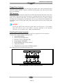
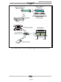
1
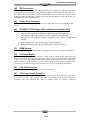
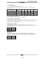
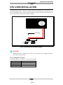
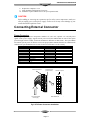
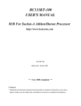
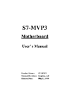
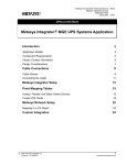
HANDLING PRECAUTIONS CAUTION High potential static charge may cause damage to the integrated circuits on the board. Before handling any mainboard outside of its protective packaging, ensure that there is no static electric charge in your body. Danger of explosion if battery is incorrectly replaced. Replace only with the same or equivalent type recommended by the manufacturer. There are some basic precautions when handling the motherboard or other computer components: ♦ Keep the board in its anti-static bag until you are ready to install it. ♦ Protect your board from static electricity by well grounding of your body and the equipment during the installation, such as wearing a grounded wrist strap. ♦ Always handle the board by its edges. ♦ Do not touch with the components on the boards, add-on cards and modules and with the “gold finger” connectors plugged into the expansion slot. It is best to handle system components by their mounting bracket. ♦ Ensure the system power is completely turn-off before doing any installation work. TRADEMARKS Intel, Pentium, Pentium II are registered trademark of Intel Corporation. IBM, IBM PC, IBM PC/AT, PC-DOS, OS/2 and OS/2 WARP are registered trademarks of International Business Machines Corporation. MS-DOS, Windows, Windows NT and Windows 95 are registered trademarks of Microsoft Corporation. AMI BIOS is a product of American Megatrends Inc. Third-party brands and names mentions in this User’s Guide are the property of their respective owners. NOTICE TO CUSTOMERS The information contains in this User’s Guide with no liability whatsoever, and disclaims any express or implied warranty, relating to sale and/or use of products including liability or warranties relating to fitness for a particular purpose, merchantability, or infringement of any patent, copyright or other intellectual property right. We shall not be liable for any loss or profits, loss of business, loss of use or data, interruption of business, or for indirect, special, incidental, or consequential damages arising from any defect or error in this User’s Guide or product. We retains the right to make changes on this User’s Guide and product descriptions at any time, without notice. User’s Guide Revision : 1.1 Release Date : March 1998 Copyright 1997,1998 All rights reserved. Table of Contents Table of Contents CHAPTER 1................................................................................................................................................... 1 FEATURES OF THE BOARD .............................................................................................................................. 1 Overview .................................................................................................................................................. 1 Features Summary.................................................................................................................................... 1 Quick Reference of Your Motherboard ..................................................................................................... 3 Motherboard Installation ......................................................................................................................... 7 CPU Card Installation ............................................................................................................................. 9 Installing System Memory (RAM) ........................................................................................................... 10 Expansion Cards Installation ................................................................................................................. 10 Connecting External Connector ............................................................................................................. 11 Page ii Motherboard Installation Chapter 1 Features of the Board OVERVIEW Congratulations on purchasing the highest performance 6ABX/LX PENTIUM II® motherboard. With the advanced technologies available today, this motherboard is designed to optimize for Intel’s PENTIUM II® processors at speeds of 100 Mhz/ 66 Mhz bus clock. Three unbuffered, 3.3 Volts, 168pin DIMM sockets are included for supporting 16MB to 512M SDRAM. A Slot 1 connector allows an easy upgrade path for the future PENTIUM II® processors. This motherboard maximum utilizes Intel's 82440BX / LX PCI chipset. The Intel 82371AB PCI/ISA IDE Xccelerator (PIIX4) provides an integrated Bus Mastering IDE controller with two high performances IDE interfaces for up to four IDE devices (such as hard drives or CD-ROM). The integrated super I/O controller integrates the standard PC I/O functions: floppy interface, two FIFO serial ports, one EPP/ECP capable parallel port, and support for an IrDA and Consumer Infra Red compatible interface. The 6ABX is designed to support the new graphic interface standard, Accelerated Graphic Port (AGP), The AGP interface can reach a theoretical ~532Mbytes/sec transfer rate for 3D graphics data. The on-board 32-bit PCI local bus slots allows a higher bandwidth data path, which serves as a super highway, for intensive data-movement such as video or networking. The BIOS support PCI bridge user configuration, which allows for further expansion of the system with PCI peripherals. Up to three 16-bit ISA slots allow this board backward hardware compatible with the older expansion card. A total of seven expansion slots may be populated with full length add-in cards, since one PCI and ISA slot share the same chassis I/O panel. FEATURES SUMMARY This motherboard comes with following features: Supports Intel PENTIUM II® Processor 233-400 or higher Mhz with automatically voltage adjustment. 100 Mhz bus for 6ABX and 66 Mhz for 6ALX. þ þ Intel 440BX for 6ABX/ LX for 6ALX PCIset, including a 82443BX PCI/Memory controller (PMC), 82371AB PCI ISA IDE Accelerator (PIIX4). þ AMI PnP BIOS with support for power management, enhanced IDE/SCSI features and desktop management interface (DMI) which allows higher level of hardware compatibility. þ Flash BIOS for a more easy upgrade path. þ Up to 3 each 168-pin DIMM sockets, supports up to 512MB SDRAM. þ One Accelerated graphic port (AGP) for AGP card. þ Three 16-bit ISA expansion slots and five 32-bit PCI expansion slots. þ Integrated two PCI bus master Ultra IDE controller with two on-board connectors supports up to four IDE devices such as Hard Disk, CD-ROM or Tape Backup drives. þ Integrated super I/O chipset featuring one floppy disk controller, two 16550 UART compatible serial ports, one high speed EPP/ECP capable parallel port, one Infra Red port. þ ATX form factor board with size 305 x 190mm Page 1 PCI 3 PCI 5 ISA 1 TB-LINK ISA 2 Fig.1 Parts Location on the Motherboard Page 2 IDE LED 1 1 1 AGP TB_LED RESET PWR ON SB-LINK JP12 JP4 F SMI POWER LED WAKEUP LINK REV. 1.00 TA-LINK JP1 4 G FLOPPY SECONDARY IDE PRIMARY IDE DIMM 3 DIMM 2 DIMM 1 JP2 440BX / LX CPU SLOT BOTTOM: KEYBOARD POWER SOCKET 6ABX / LX D SPEAKER I USB J3 82371 H COM 1 C PARALLEL B BIOS COM 2 A TOP: MOUSE Motherboard Installation J2 CPU FAN S R Q P O N E M PCI 1 L PCI 2 JP7 JP8 JP9 JP10 PCI 4 K J Motherboard Installation QUICK REFERENCE OF YOUR MOTHERBOARD A PS/2 Keyboard / Mouse Connectors K. Intel SB82371AB Chipset B Universal Serial Bus (USB) Connectors L. Infra-Red (IR) Connector C External I/O Connectors M. IDE device connector D PENTIUM II CPU Card Slot N. Floppy Drive Connector E Accelerated Graphic Port (AGP) O. Intel SB82443BX Chipset F Integrated I/O Controller P. G Flash BIOS Q. 3V Lithium Battery H PCI Add-in Board Connectors R. CPU FAN Connector I ISA Add-in Board Connectors S. J Front Panel Function Connectors 3.3v DIMM Sockets ATX Power Supply Connector ATX Form Factor Motherboard ATX is an evolution of the popular Baby-AT form-factor defined to address four major areas of improvement over today’s predominant form factors: enhanced ease-of-use, better support for current and future I/O and better support for current and future processor technology. This motherboard is designed to fit into a standard ATX form factor chassis in that the outer dimensions are 12" x 9.6" (30.48 cm x 24.38 cm). The location of I/O connectors, CPU socket, PCI and ISA slots, and mounting holes are also strictly based on the ATX specification. By simply rotating the board through 90 degrees (with respect to baby -AT form factor) within the chassis, the end-user gains a great deal in ease-of-use and improved functionality. • • • • • • • With the processor relocated, all expansion slots can be full-length. Since the processor is not located between or under the add-in cards, a processor upgrade can now be performed without removing the installed cards. The SIMM connectors can be relocated away from the expansion bays and slots, increasing ease-of-use by giving easy access to the user for memory upgrades, and increasing the total number of available full length slots. The use of only one fan within the system reduces noise levels. More I/O is integrated onto the baseboard, improving reliability and reducing the number of cables. Disk I/O connectors are located closer to the peripheral bays, reducing cable lengths. This reduces the clutter in the chassis and allows the use of faster hard disk drives. With increased ease of use, and a reduction in cable complexity, the technical support burden is lowered. Page 3 Motherboard Installation [A] PS/2 Keyboard / Mouse Connectors PS/2 device, likes some PS/2 keyboard and mouse, are all have a standard 6-pin round shape connector. The benefit of PS/2 device is one of the serial port may be free for other serial device such as writing table. On this motherboard, there are two on-board PS/2 connectors, one for keyboard and one for mouse, which saves your money to buy any optional PS/2 connector module. If you are using a PS/2 mouse or keyboard, you can simply plug into the corresponding connector without any jumper setting. [B] USB Connectors Universal Serial Bus (USB) is new interface standard for any I/O device “Outside the Box”. USB makes your peripherals have a real plug and play (PnP) capabilities with up to 12Mb/sec data speed In the coming soon, any external device connected to your computer will be standardized into USB standard which are all have a special 4-pin rectangle shape connector. Therefore, with the Intel chipset, this motherboard builds two USB connectors on-board for you future investment. [C] External I/O Connectors Based on the ATX standard, two 9-pin serial ports and one 25-pin parallel port are now built on the motherboard back panel, too! This design makes your motherboard’s installation more easily. The parallel port can be BIOS configured into standard (SPP) mode, Enhanced Parallel Port (EPP) mode, and a high speed Extended Capabilities Port (ECP) compatible mode. EPP Mode requires a driver provided by the peripheral manufacturer in order to operate correctly. [D] PENTIUM II® CPU CARD Slot The CPU card slot, slot 1, is a 242-pin slot design for PENTIUM II, single edge contact cartridge, along with a programmable voltage regulator for the CPU core. It provides users with a performance upgrade path to PENTIUM II® OverDrive technology. The motherboard built-in a switching voltage regulator which supports from 2.1V to 3.5V PENTIUM II processors. The regulator makes use of the VID capabilities to automatically adjust its voltage output to match that of the installed processor, which eliminated the traditional jumper settings. PENTIUM II PROCESSOR CARD The PENTIUM II processor integrates second level cache and cache controller that was previously implemented on the motherboard. The internal non-blocking L2 cache on the processors card is 512k KB cache. The PENTIUM II® processor card maintains full backward compatibility with the 8086, 80286, Intel386TM, Intel486TM and Pentium® processors. It also has a numeric coprocessor that significantly increases the speed of floating point operations, while maintaining backward compatibility with the i486DX math coprocessor and complying with ANSI/IEEE standard 754-1985. [E] Accelerated Graphic Port (AGP) The AGP is compatible with the Accelerated graphics port specification. The AGP offers a much higher throughput over the PCI bus does. PCI currently only supports 33Mhz can transport 133MB/s at peak rates over its 32bit data bus. AGP is clocked with 66Mhz, which enables a peak rate of 266 MB/s at the classic so called ‘X1’ mode. If using the ‘X2’ mode, it can transport up to 532MB/s at peak rate. Page 4 Motherboard Installation [F] Integrated I/O Controller On the motherboard, serial ports, parallel port and floppy drive is integrated into a single chip. The I/O port allows you to configure through the BIOS setup. This integrated I/O chip provides: • • • • • • Plug-and-Play, Version 1.0a compatible. Built In RTC devices Supports two 360K, 720K, 1.2M, 1.44, 2.88M floppy disk drives One multi-mode parallel port, which can be configured as standard (SPP) mode, enhanced (EPP) mode, high speed (ECP) mode. Supports two 16C550 compatible enhanced serial ports. Supports IrDA or ASKIR infrared interface. [G] Flash BIOS The flash BIOS allows user have more flexibility to upgrade their motherboard. The flash BIOS can be programmed by software easily. For the latest BIOS upgrade information, please feel free to visit our web site: http://www.zida.com [H] PCI Add-in Board Connectors This motherboard provides four 32-bit PCI slots with up to 133MB/sec burst data transfer rate. [I] ISA Add-in Board Connectors This motherboard provides three 16 bit ISA slots, which allows backward hardware compatibility. [J] Front Panel Function Connectors All the front panel indicator, speaker, and switch functions are grouped into an on-board 26-pin panel function connector. [K] 82371AB PCI/ISA IDE Accelerator (PIIX4) The Intel 82371AB is a 392-pin BGA package IC which provides the following features: • • • • • [L] Interface between the PCI local bus and ISA bus. Supports for 2 Universal Serial Bus (USB) ports. Integrated fast IDE interface, which supports up to 4 devices. With separated Master/Slave mode support, it provides data transfer rate up to 33 MB/sec in UltraDMA mode. In addition, it also integrated an 8 x 32-bit buffer for Bus Master IDE PCI burst transfers, which further enhanced the system performance. Ultra-DMA controller with Fast Type-F DMA Counters/Timers, which provides advanced power management with programmable system management interrupt (SMI). Infra-Red (IR) Support A 5-pin interface on the front panel I/O connector is provided to allow connection to a Hewlett Packard HSDSL-1000 compatible Infrared (IrDA) transmitter/receiver. Once the module is connected to the front panel I/O header, Serial port 2 can be re-directed to the IrDA module. When configured for IrDA, the user can transfer files to or from portable devices such as laptops, PDA’s and printers using application software such as LapLink. The IrDA specification provides for data transfers at 115kbps from a distance of 1 meter. Support for Consumer infrared (ASK-IR) is also included, please refer to your IR equipment for more detailed information. Page 5 Motherboard Installation [M] IDE Connectors This motherboard have two independent high performance bus-mastering PCI IDE interfaces capable of supporting up to Mode 4 devices. The system BIOS supports automatic detection of the IDE device data transfer rate and translation between different kinds of device mode such as Logical Block Addressing (LBA) and Extended Cylinder Sector Head (ECSH) translation modes and ATAPI (e.g., CD-ROM) devices on both IDE interfaces. [N] Floppy Drive Connector A 34-pin connector on-board allows connection to two 360K, 720K, 1.2M, 1.44, 2.88M floppy disk drives. [O] 82443BX / LX PCI Bridge, AGP and Memory Controller (PAC) The 82443BX/LX comes in a 492 pin BGA package and provides the following features: • • • • • [P] CPU interface control up to 100Mhz for 6ABX with true 32-bit addressing. CPU interface control up to 66Mhz for 6ALX with true 32-bit addressing Integrated 64/72-bit DRAM controller, supporting from 8 MB to 512MB main memory. Fully synchronous PCI bus interface with 33 MHz bandwidth. Write data Buffering and supports PENTIUM II -to-PCI burst writes. DIMM Sockets Four 168 pins standard DIMM socket allows your system using either for 3.3V unbuffered SDRAM. [Q] 3V Lithium Battery An on-board battery holder is used to hold a 3 Volts CR-2032 Lithium battery which makes the battery’s replacement more convenient. This battery is used to supply power for the RTC CMOS RAM in order to save your system setting and date/time counting during system power-off. In general, the battery’s lifetime is about 5 years. If you see a “BIOS checksum error” message happened while system turn-on, the battery low may cause it. You can try to fix it by simply replaced the battery. [R] CPU FAN Connector The CPU FAN connector allows you attach your CPU card fan here. [S] ATX Power Supply Connector Based on the ATX specification, one 20-pin power connector covers all the required power sources, ±5V, ±12V and ±3.3V, with soft-touch button power on/off features. This connector reduces the installation time and minimizes the chance of defects caused by incorrect connection Page 6 Motherboard Installation MOTHERBOARD INSTALLATION Installation Precautions During installation and initial test, use caution to avoid personal injury and damage to wiring due to sharp pins on connectors and printed circuit assemblies, rough chassis edges and corners, and hot components. Adhere to warnings and limitations regarding accessibility into areas designated only for authorized technical personnel. A Quick Introduction To Install and operate your the new motherboard, you must follow the steps below: 1. 2. 3. 4. 5. Set Jumpers on the motherboard Install the CPU with cooling fan Install RAM modules Connect cables, wires and power connector Install expansion cards Jumpers Setting There are several user-adjustable jumpers on the board, which allow you to configure your system to match your requirements. This chapter contains the information on the various jumpers settings and connector on your motherboard. Jumpers Jumpers are used to make several hardware settings on the motherboard. From the “Map of the Motherboard” shown above, you can identify the location of the jumpers. There are two kinds of ”, “ ” jumper on-board, 2-pin jumper and 3-pin jumper. On the symbol of jumper likes “ inside stands for pin 1. To set a jumper, a black cap containing metal contacts is placed across the jumper pin/s according to your required configuration. The jumper settings will also be described numerically such as [open] for open, [short] for short, [1-2] for connect pins 1&2, [2-3] for connects pins 2&3 respectively. Pin 1 symbol on the silk screen Black cap Onboard jumper Pin 1 Pin 2 Pin 3 CAUTION Users are not recommended to change any jumpers in it’s default setting listed on this User’s Guide. Changing the jumper settings improperly may affect the system performance. Page 7 Motherboard Installation CPU Speed Selection • JP7-JP10 for frequency ratio setting The table below shows the jumper setting for the Pentium II and Celeron. CPU and it based on its internal clock speed. Internal CPU speed (Mhz) 100 / 66 Mhz bus speed 350 / 233 400 / 266 450 / 300 500 / 333 External Bus 6ABX / 6ALX 100 / 66 Mhz 100 / 66 Mhz 100 / 66 Mhz 100 / 66 Mhz JP10 JP9 JP8 JP7 [close] [close] [close] [close] [close] [open] [open] [open] [open] [close] [close] [open] [open] [close] [open] [close] Frequency Ratio 3.5x 4x 4.5x 5x *Celeron is running at 66Mhz bus only *Please refers to your CPU specification for proper jumper setting. Voltage Regulator Output Selection As mentioned before, the on-board regulator makes use of the VID capabilities to automatically adjust its voltage output to match that of the installed processor. Therefore, jumper setting is no longer required for this item on PENTIUM II CPU. 66 Mhz support on 6ABX The 6ABX main board is optimal for 100 Mhz bus design, 66Mhz bus on this board is not recommended. However, if you want to use a 66Mhz CPU, we provide a jumper for you to slow down the bus for this option. Jumper 66Mhz 100Mhz JP3 CLOSE OPEN CMOS Reset If you want to reset the CMOS data, you need to turn off the main power switch of the system power supply and remove the jumper and reinstall it. After the CMOS reset, all the system BIOS configuration will lose at all and please re-enter the CMOS setup screen to setup the system again. Jumper Normal Reset JP2 1-2 2-3 Page 8 Motherboard Installation CPU CARD INSTALLATION The motherboard provides a 242-pin CPU card slot. The CPU card should have a fan attached to it to prevent overheating. If this is not the case then purchase a fan before you turn-on the system. There are two CPU fan power connector, JP2 and JP3, on-board. CPU COOLING FAN +12V (Red) Ground (Black) J3 J4 Fig. 3 CPU Cooling Fan Installation Diagram CAUTION Without an effective cooling fan, the CPU can overheat and cause damage to both the CPU and the motherboard. CPU Cooling fan Connector J3 and J4 provide the +12 Volts D.C. for your CPU cooling fan J3 and J4 Pin 1 2 3 Signal Name Ground +12V Ground Page 9 Motherboard Installation INSTALLING SYSTEM MEMORY (RAM) The motherboard supports three 168-pin DIMM. The three 168-pin DIMM sockets are divided into six banks for single or double side SDRAM DIMM. Vertically insert for installation 64 Bit 168 PIN DIMM Module Push to remove DIMM module 3.3V Key Unbuffered DRAM Key Push to remove DIMM module Fig. 4 168-Pin DIMM Module Installation Diagram Expansion Cards Installation At the most of beginning, you must read your expansion card documentation on any hardware and software settings that may be required. The installation procedures are summarized as below: 1. Read the User’s Guide/Manual of your expansion card. 2. If necessary, set any jumpers on your expansion card. 3. Power-off the system and then disconnected the power cord. 4. Remove your computer’s cover. 5. Remove the metal bracket from one of the empty slot, ISA or PCI, corresponding to the type of expansion card. 6. Carefully align the card’s connectors and press firmly, make sure at the connection is good. 7. Secure the card on the slot. Page 10 Motherboard Installation 8. Replace the computer’s cover. 9. Setup the BIOS configuration if necessary. 10. Install the required software drivers for your expansion card. CAUTION Before adding or removing any expansion card or other system components, make sure that you unplug your system power supply. Failure to do so may cause damage of your motherboard and expansion cards. Connecting External Connector Power Connector PW1, single 20-pin connector incorporates standard ±5V and ±12V, optional 3.3V and soft-power signals. With a power supply, supports remote power on/off, the motherboard can turn off the system power through software control, such as the shutdown in Windows 95 Start menu. The system BIOS will turn the system power off when it receives the proper APM command from the OS. APM must be enabled in the system BIOS and OS in order for the soft-off feature to work correctly. Pin 1 2 3 4 5 6 7 8 9 10 Signal Name +3.3V +3.3V Ground +5V Ground +5V Ground PWRGOOD +5VSB +12V ATX Power Connector Pin 11 12 13 14 15 16 17 18 19 20 Signal Name +3.3V -12V Ground PW_ON Ground Ground Ground -5V +5V +5V Connector's Lock (push to release) Onboard receptacle PW1 From ATX Regulated 6DXP Motherboard Power Supply Fig.5 ATX Power Connector Installation Page 11 Motherboard Installation Floppy Drive Connector This 34-pin connector supports the provided floppy drive ribbon cable. After connecting the single end to the on-board “FLOPPY” connector, connect the remaining plugs on the other end to the floppy drives correspondingly. IDE Connector The two on-board IDE connectors support the provided 40-pin IDE hard disk ribbon cable. After connecting the single end to the board, connect the two remaining plugs at the other end of your hard disk(s). If you install two hard disks, you must configure the two drives by setting its jumpers according to the documentation of your hard disk. Also, you may connect the two hard disks to be both Masters using one ribbon cable on the primary IDE connector and one on the secondary IDE connector. NOTICE For the flat ribbon cable connection, please make sure that the pin 1 of the ribbon cable (the red wire side of the cable) is correctly connected to the on-board connector’s pin 1 as shown on the “Map of the Motherboard”. Front Panel Function Connector All the front panel indicator, speaker, and switch functions are grouped into an on-board 26-pin connector, JP9. Front panel features supported include: • • • • • • • System Reset, RESET Power LED, form KEYLOCK Hard Drive activity LED, IDE LED System Speaker, SPEAKER Soft-touch button power on/off, SW ON Turbo LED, TBLED External power saving control, EXTSMI (optional) The connector pin out are described as the figure below: SPEAKER EXTSMI SPKR GND VCC GND KEYLOCK GND EXT SMI GND KEY LOCK PW LED 13 26 14 GND GND GV VR VCC RST PUSH ON TBLED RESET SW ON GND IDE LED IDE LED Fig.6 The Onboard Function Connector Pin Out Page 12 Motherboard Installation About Soft Touch Power Button For the ATX system case, the new soft touch power button replaces the main power switch to switch ON / OFF your system. You can switch the system ON by pressing the button. If you want to switch OFF your system, press the button and hold it for 4 seconds. You can also change the functions of the power button in the CMOS setup at power management section. Infra-Red connector Serial port 2 can be configured to support an IrDA module via a 5-pin header connector. Once configured for IrDA, the user can transfer files to or from portable devices such as laptops, PDA’s and printers using application software such as LapLink. The IrDA specification provides for data transfers at 115 Kbps from a distance of 1 meter. Consumer IR is also supported by the same connector. JP5 Pin 1 2 3 4 5 Signal Name VCC, power source N/C IRRX, infra-red receive N/C IRTX, infra-red transmit I/O Back Panel Connectors The I/O back panel allows external access to PS/2 keyboard and mouse connectors as well as two serial ports, and one parallel port, which are integrated on the motherboard. The following figure showed the location of the I/O connectors. PS/2 MOUSE PRINTER KEYBOARD PARALLEL SERiAL SERiAL COM 1 COM 2 USB CONNECTOR (FRONT VIEW) PS/2 MOUSE KEYBOARD PS/2 Plug USB CONNECTOR 1 USB CONNECTOR 2 USB Plug Fig.7 I/O Back Panel Connector Installation Diagram for PS/2 and USB Page 13 Motherboard Installation 26-pin (Female) Connector 26-pin Parallel Port (Male) connector SERIAL SERIAL Onboard Back I/O Connector PRINTER EXTERNAL MODEM Onboard Back I/O Connector PARALLEL 9-pin Seriall Port (Female) connector 9-pin (Male) Connector COM 1 COM 2 SERIAL MOUSE Fig. 8 I/O Back Panel Connector Installation Diagram for Serial and Parallel Ports Page 14 Manual Revision History REVISION HISTORY v v Revision 1.0 Revision 1.1 First release. Add Celeron CPU settings Page 15