1
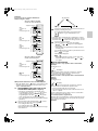
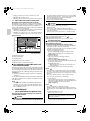
00_CV_3P034927-5J.fm Page 1 Saturday, November 19, 2005 4:42 PM OPERATION MANUAL Total Heat Exchanger HRV (Heat Reclaim Ventilation) English Español MODELS (Ceiling mounted duct type) VAM 150GJVE VAM 250GJVE VAM 350GJVE VAM 500GJVE VAM 650GJVE VAM 800GJVE VAM 1000GJVE VAM 1500GJVE VAM 2000GJVE Portugues Ðóññêèé 00_CV_3P034927-5J.fm Page 2 Saturday, November 19, 2005 4:42 PM HRV HRV; Heat Reclaim Ventilation Before using the DAIKIN HRV, be sure to read this operation manual thoroughly. If you have any problems or there is a malfunction, please refer to this operation manual. Please keep this manual for your future reference whenever you do not understand how to use it when something is wrong with the unit during the operation. HRV;Ventilación con recuperación de calor Antes de utilizar el HRV de DAIKIN, lea cuidadosamente este manual de funcionamiento. Si tiene algún problema o hay un mal funcionamiento, consulte este manual de funcionamiento. Por favor conserve este manual para poder consultarlo cuando no entienda cómo utilizar la unidad o cuando algo falle durante su funcionamiento. HRV;Ventilação de Recuperação Térmica Antes de utilizar o DAIKIN HRV, leia atentamente este manual. Caso tenha algum problema ou se existe alguma falha no funcionamento, consulte este manual. Guarde este manual para futuras consultas sempre que não souber como utilizar ou se existir algum problema com a unidade durante a operação. HRV; Вентиляция с реãенерацией тепла До начала работы с DAIKIN HRV внимательно изóчите данное рóêоводство по эêсплóатации. При возниêновении любых нарóшений работы или проблем обращайтесь ê данномó рóêоводствó по эêсплóатации. Сохраняйте данное рóêоводство для бóдóщих обращений при любых сложностях в работе с блоêом или нарóшениях еãо фóнêционирования. HRV; Isý Geri Kazaným Vantilasyonu DAIKIN HRV’yi kullanmadan önce, bu kullaným kýlavuzunu tamamýyla okuduðunuzdan emin olun. Herhangi bir problemle karþýlaþmanýz veya bir arýza olmasý durumunda, lütfen bu kullaným kýlavuzuna baþvurun. Ýþletme sýrasýnda ünitede bir sorun olduðunda nasýl kullanýlacaðýný anlamadýðýnýz ileriki zamanlarda baþvurmak üzere lütfen bu kýlavuzu saklayýn. 00_CV_3P034927-5J_Illust.fm Page 1 Thursday, November 24, 2005 3:46 PM MODELS VAM150GJVE VAM250GJVE VAM350GJVE VAM500GJVE VAM650GJVE VAM800GJVE VAM1000GJVE 1 [1] 00_CV_3P034927-5J_Illust.fm Page 2 Thursday, November 24, 2005 3:46 PM MODELS VAM1500GJVE (3) Exhaust fan VAM2000GJVE (1) Hanger bracket (7) Maintenance cover (2)Duct connecting flange (6) Control box (10) Air supply fan (5) Damper (4) Air filter (Long life filter) (8) Heat exchange elements It exchanges the heat (temperature and humidity) from indoors with the air taken in from outdoors, changes the outside air to the same condition as indoors and then brings it indoors. (11) Remote controller (Optional accessory) Important Sometimes when first using the unit, the smell of the heat exchanging element may be noticeable, but it is not harmful. The smell will gradually go away as the unit is used. (15) Maintenance space for the air filters, the heat exchange elements and control box (14) OA (Outdoor air) [Fresh air from outdoors] (17) SA (Supply air) [Supply air to room] (13) EA (Exhaust air) [Exhaust air to outdoors] (16) RA (Retun air) [Return air from room] 1 [2] (12) Damper motor 00_CV_3P034927-5J_Illust.fm Page 3 Thursday, November 24, 2005 3:46 PM • Independent system HRV unit • Centralized system HRV unit Centralized controller Remote controller for HRV unit (BRC301B61) Remote controller for HRV unit (BRC301B61) Remote controller for indoor unit • Combined operation system with VRV systems and Sky-air series Indoor unit Indoor unit HRV unit HRV unit Remote controller Remote controller for indoor unit for HRV unit (BRC301B61) Remote controller for indoor unit 2 25 NOT AVAILABLE 27 Remote controller for VRV BRC1A61, 62 Remote controller for HRV BRC301B61 NOT AVAILABLE Remote controller for VRV BRC1C61 3 [3] 00_CV_3P034927-5J_Illust.fm Page 4 Thursday, November 24, 2005 3:46 PM 1·4 1·4 1·4 2 3 2 3 Remote controller for HRV BRC301B61 Remote controller for VRV BRC1C61 Remote controller for VRV BRC1A61, 62 4 1 1 1 3 2 Remote controller for HRV BRC301B61 3 3 2 Remote controller for VRV BRC1C61 2 Remote controller for VRV BRC1A61,62 5 MODELS VAM150GJVE - 1000GJVE MODELS VAM1500GJVE VAM2000GJVE 6 MODELS VAM150GJVE - 1000GJVE 7 [4] MODELS VAM1500GJVE VAM2000GJVE 00_CV_3P034927-5J_Illust.fm Page 5 Thursday, November 24, 2005 3:46 PM 8 9 10 [5] 3P034927-5_En.fm Page 1 Sunday, October 30, 2005 3:24 PM VAM150GJVE VAM250GJVE VAM350GJVE VAM500GJVE VAM650GJVE VAM800GJVE VAM1000GJVE VAM1500GJVE VAM2000GJVE Total Heat Exchanger HRV (Heat Reclaim Ventilation) CONTENTS 1. 2. 3. 4. 5. 6. 1. ILLUSTRATIONS .................................................... [1]~[5] SAFETY CAUTIONS .......................................................1 WHAT TO DO BEFORE OPERATION ...........................2 OPERATION PROCEDURE ...........................................4 MAINTENANCE (for a qualified service person only) .....7 TROUBLE SHOOTING ...................................................8 AFTER-SALES SERVICE .............................................10 SAFETY CAUTIONS Read the following cautions carefully and use your equipment properly. This unit comes under the term “appliances not accessible to the genetic public.” There are two kinds of safety cautions and tips listed here as follows: WARNING ............... Improper handling can lead to such serious consequences as death or severe injury. CAUTION ................Improper handling can lead to injury or damage. It could also have serious consequences under certain conditions. NOTE • These instructions will ensure proper use of the equipment. Be sure to follow these important safety cautions. Keep these warning sheets handy so that you can refer to them if needed. Also, if this equipment is transferred to a new user, make sure to hand over this user’s manual to the new user. WARNING (During Operation) • When the unit is in abnormal conditions (smell of something burning, etc.), cut off the power, and contact your dealer. Continued operation under such circumstances may result in a failure, electric shock, and fire. • It is not good for your health to expose your body to the air flow for a long time. • Do not operate the unit with a wet hand. An electric shock may result. • Open the windows and ventilate the room if flammable gas is leaked. Insufficient ventilation when the unit is turned on or off may cause an explosion from sparks at the electrical connection. • Do not wash the HRV unit with water. Electric shock or fire may result. (Not including air filters, etc.) • Be sure to stop the unit and turn off the power when cleaning or inspecting it. As the fan is rotating at high speed, it will cause injury. • Never inspect or service the unit by yourself. Ask a qualified service person to perform this work. (The qualified service person) CAUTION (During Operation) • Do not use the HRV unit for other purposes. In order to avoid any quality deterioration, do not use the unit for cooling precision instruments, food, plants, animals or works of art. • Do not use burning appliances directly in the path of the air from the unit. Incomplete combustion of the burning appliances may occur. 1 Operation manual • Never expose little children, plants or animals directly to the air flow. Adverse influence to little children, animals and plants may result. • Neither place a flammable spray bottle near the HRV unit or indoor intake and outlet grills nor perform spraying. Doing so may result in a fire. • Turn off the power when the unit is not to be used for long periods of time. Otherwise, the unit may get hot or catch on fire due to dust accumulation. • Do not block the intake or outlet grills. If the fan does not blow air throughout the entire room it may cause machine trouble. • Use gloves when cleaning. Cleaning without gloves may cause injury. • Do not operate the remote controller with wet hands. This may cause electric shock. • Never touch the internal parts of the controller. Do not remove the front panel. Some parts inside are dangerous to touch, and a machine trouble may happen. For checking and adjusting the internal parts, contact your dealer. • Do not let any kind of sprays get on the remote controller (insecticides, cleaning materials, etc.) This may cause breakage, deformation, or malfunction. • Do not wipe the controller operation panel with benzine, thinner, chemical dustcloth, etc. The panel may get discolored or the coating peeled off. If it is heavily dirty, soak a cloth in water-diluted neutral detergent, squeeze it well and wipe the panel clean. And wipe it with another dry cloth. • The appliance is not intended for use by young children or infirm persons without supervision. • Young children should be supervised to ensure that they do not play with the appliance. • Consult with installation contractor for cleaning the inside of the air conditioner. Wrong cleaning may make the plastics parts broken or cause failure of water leakage or electric shock. • Do not place objects in direct proximity of the outdoor unit and do not let leaves and other debris accumulate around the unit. Leaves are a hotbed for small animals which can enter the unit. Once in the unit, such animals can cause malfunctions, smoke or fire when making contact with electrical parts. WARNING (For installation) • Do not attempt to install the unit yourself. Ask your dealer for installation of the unit. Incomplete installation performed by yourself may result in a water leakage, electric shock, and fire. • Installation should be done following the installation manual. Incorrect installation may cause leaking, electric shock, or fire. Injuries may result if the unit falls. • Do not allow exhaust air to enter the outside air intake vent. This may cause the interior of the room to become contaminated and harming the health. • Locate the outside air intake vent so that it does not take in exhaust air which contains combustion air, etc. Incorrect installation may cause a loss of oxygen in the room, leading to serious accidents. English 3P034927-5_En.fm Page 2 Sunday, October 30, 2005 3:24 PM • All wiring must be performed by an authorized electrician. To do wiring, ask your dealer. Never do it yourself. • Make sure that a separate power supply circuit is provided for this unit and that all electrical work is carried out by qualified personnel according to local lows and regulations. Insufficient power circuit capacity or incorrect work may cause electric shock or fires. • Install the unit on a foundation strong enough to withstand the weight of the unit. A foundation of in sufficient strongth may result in the unit falling and causing injuries. • Connect the remote controller to the correct model. This may cause electric shock or fire. • Do not connect additional electric wirings. This may cause fire. • Do not install the HRV unit at any place where flammable gas may leak out. If the gas leaks out and stays around the unit, a fire may break out. • Be sure to establish an earth. Do not earth the unit to a utility pipe, arrester, or telephone earth. Incomplete earth may cause electrical shock, or fire. A high surge current from lightning or other sources may cause damage to the air conditioner. • Be sure to install an earth leakage breaker. Failure to install an earth leakage breaker may result in electric shocks, or fire. CAUTION (For installation) • Do not use the HRV unit or an air suction/discharge grille in the following places. a. Place subjected to high temperature or direct flame. Avoid a place where the temperature near the HRV unit and the air suction/discharge air grille exceeds 40°C. If the unit is used at high temperature, deformed air filter and heat exchange element or burned motor result. b. Place such as kitchens or other places where oil fumes are present. This may cause fire. c. Place such as machinery plant and chemical plant where gas, which contains noxius gas or corrosive components of materials such as acid, alkali, organic solvent and paint, is generated. Place where combustible gas leakage is likely. This may cause gas poisoning or fires. d. Place such as bathroom subjected to moisture. Electric leak or electric shock and other failure can be caused. e. Locations below freezing point. f. Near machinery emitting electromagnetic waves. Electromagnetic waves may disturb the operation of the control system and result in a malfunction of the equipment. g. Place subjected to much carbon black. Carbon black attaches to air filter and heat exchange element, marking them unable to use. • Is a snow protection measure taken? For detail, consult your dealer. • Make sure the temperature and the humidity of the installation location is within the usage range, not exceed the limit. Do not install in cold storage or other locations with low temperatures or near heated pools. This may cause fires or short circuits. English • Install the two outdoor ducts with down slope to prevent rainwater from entering the unit. If this is not done completely, water may enter the building, damaging furniture, and cause electric shock and fire. • Insulate the two outdoor ducts to prevent dew condensation (and the indoor duct as well if needed). If this is not done completely, water may enter the building, damaging furniture, etc. • Use electric insulation between the duct and the wall when using metal ducts to pass metal or wire laths or metal plating into wooden buildings. This may cause electric shock, short circuits, or fire. • Arrange the drain hose to ensure smooth drainage. Incomplete drainage may cause wetting of the building, furniture etc. • Avoid placing the controller in a spot splashed with water. Water coming inside the controller may cause an electric leak or may damage the internal electronic parts. • Never pull or twist the electric wire of a remote controller. It may cause the unit to malfunction. (For moving and reinstalling/ WARNING repairing) • Do not modify the unit. This may cause electric shock or fire. • Ask your dealer to move and reinstall the unit. Incomplete installation may result in electric shock, and fire. • Do not disassemble or repair the unit yourself. This may cause electric shock or fire. Contact your dealer to have such work done. • When removing the unit, be sure not to tip it. The water inside the unit may drip or leak out, and get on furniture, etc. • Do not move or attempt to re-install the remote controller yourself. Incorrect installation, may cause electric shock or fire. Contact your dealer to have such work done. 2. WHAT TO DO BEFORE OPERATION This operation manual is for the following systems with standard control. Before initiating operation, contact your Daikin dealer for the operation that corresponds to your system type and mark. If your installation has a customized control system, ask your dealer for the operation that corresponds to your system. 2-1 NAMES OF PARTS (Refer to figure 1) (1) Hanger bracket (2) Duct connecting flange (3) Exhaust fan (4) Air filter (Long life filter) (5) Damper (6) Electric parts box (7) Maintenance cover (8) Heat exchanger elements (9) Name plate (10)Air supply fan (11)Remote controller (Optional accessory) (12)Damper motor (13)EA Exhaust air to outdoors (14)OA Fresh air from outdoors (15)Maintenance space for the air filters, the heat exchange elements and control box. (16)RA Return air from room (17)SA Supply air to room 2 3P034927-5_En.fm Page 3 Sunday, October 30, 2005 3:24 PM 2-2 REMOTE CONTROLLER AND CHANGEOVER SWITCH: NAME AND FUNCTION OF EACH SWITCH AND DISPLAY (Refer to figure 3) • Only the items marked with an asterisk (∗ mark) are explanation relating to the functions and display of the unit. Unmarked items are functions of the combined air conditioners. When using buttons for functions which are not available (buttons which are not described in the text) will cause “NOT AVAILABLE” to be displayed. Contact your dealer for more detailed descriptions of those functions (buttons). ∗1 On/off button Press the button and the system will start. Press the button again and the system will stop. ∗2 Operation lamp (red) The lamp lights up during operation. ∗3 Display “ ” (changeover under control) May be displayed when combined with a VRV-system air conditioner. While the indication is shown, the ON/OFF of HRVs cannot be operated by the HRV remote controller. It is impossible to changeover heat/cool with the remote controller when this icon is displayed. 4 Display “ ” (air flow flap) This displays the direction and mode of the air flow flap of the combined air conditioner. 5 Display “ ” (ventilation/air cleaning) This display shows that the total heat exchange and the air cleaning unit are in operation. (These are optional accessories.) 6 Display “ C ” (set temperature) This displays the set temperature of the combined air conditioner. It is not displayed when the unit is used as an independent system. 7 Display “ ”“ ”“ ”“ ”“ ” (operation mode) This displays the operating status of the combined air conditioner. • There is no “heating” for the VRVII system (Cooling only type). • “ ” is only available for systems operating in cooling and heating at the same time. ∗8 Display “ ” (programmed time) This display shows the programmed time of the system start or stop. 9 Display “ TEST ” (inspection/test operation) When the inspection/test operation button is pressed, the display shows the mode in which the system actually is. • Do not use under usual use (service person/installer only). 10 Display “ ” (under centralized control) When this display shows, the system is under centralized control. (This is not a standard specification.) During this indication appears on the display, the ON/ OFF and timer operation may not be possible with the HRV remote controllers. ∗11 Display “ ” (fan speed) This display shows the fan speed you have selected. This is always displayed when you use the remote controller BRC301B61. But, this is only displayed when the fan speed selection button is pressed. It normally displays the set fan strength of the combined air conditioner. (only to use BRC1C61, BRC1A61, A62) ” (time to clean air filter) ∗12 Display “ Refer to “4-1 HOW TO CLEAN THE AIR FILTER”. 3 13 Display “ ” (defrost/hot start) It may be displayed when the combined air conditioner is in heating mode. ∗14 Timer mode start/stop button Refer to the chapter “Operation procedure Programming start and stop of the system with timer.” (3-2) ∗15 Timer on/off button Refer to the chapter “Operation procedure Programming start and stop of the system with timer.” (3-2) ∗16 Inspection/test operation button Pressed during inspection or “test run.” • Do not use under usual use. (service person/installer only) ∗17 Programming time button Use this button for programming start and/or stop time. 18 Temperature setting button Use this button for setting the desired temperature of air conditioner combined with this unit. ∗19 Filter sign reset button Refer to “4-1 HOW TO CLEAN THE AIR FILTER”. 20 Fan speed control button Press this button to select the fan speed of air conditioner combined with this unit. ∗21 Operation mode selector button Press this button to select the operation mode of air conditioner combined with this unit. 22 Air flow direction adjust button Press this button to select the air flow direction of air conditioner combined with this unit. 23 Fan only/air conditioning selector switch Set the switch to “ ” for fan only operation or to “ ” for heating or cooling operation. 24 Cool/heat changeover switch Set the switch to “ ” for cooling or to “ ” for heating operation. 25 Remote controller thermo This detects the temperature around the remote controller. This is not the same as the temperature of return air from room (RA) by heat exchanger unit. ∗26 Display “ ”“ ”“ ” This displays the ventilation mode. (BRC301B61, BRC1C61 and so on.) (This is not displayed on the controller BRC1A61, 1A62) ∗27 Display “NOT AVAILABLE” • “NOT AVAILABLE” may be displayed for a few seconds if the function for the button pressed is not available for the unit or the air conditioner. • “NOT AVAILABLE” is only displayed when none of the indoor units is equipped with the function in question when running several units simultaneously. It is not displayed if the function is available on even one of the units. ∗28 Ventilation fan mode selector button (available only connecting the HRV unit) This is pressed to switch the fan mode of the HRV unit. ∗29 Ventilation fan speed control button (available only connecting the HRV unit) This is pressed to control the fan speed of the HRV unit. (Refer to item 11) ∗30 Display “ ” (operation standby) It indicates the pre-cooling/pre-heating operation. This unit is at stop and will start operation after the pre-cooling/pre-heating operation is over. Pre-cooling/pre-heating operation means the operation of HRVs is delayed during the startup operation of linked air conditioners such a before the office hours. During this period the cooling or heating load is reduced to bring the room temperature to the set temperature in a short time. English 3P034927-5_En.fm Page 4 Sunday, October 30, 2005 3:24 PM 31 Display “FRESH UP” This displays the status of two fans. Refer to “OPERATION PROCEDURE” NOTE • In contradistinction to actual operating situations, the display on figure 3 shows all possible indications. • If the filter sign lamp lights up, clean the air filter as explained in the chapter “MAINTENANCE”. After cleaning and reinstalling the air filter: press the filter sign reset button on the remote controller. The filter sign lamp on the display will go out. 2-3 Explanation for SYSTEMS This unit can be made a part of two different systems: as part of the combined operation system used together with VRVII SYSTEM Air Conditioners or Sky-air series and as the independent system using only the HRV. An operating remote controller is required when using the unit as an independent system. Ask your dealer what kind of system your system is set up for before operation. For the operation of the remote controller for indoor unit and centralized controller, refer to the instruction manual provided with each unit. See the included operating manuals for details on how to operate each remote control. OPERATION for EACH SYSTEM Sample system (Refer to figure 2) Independent system [Operation] The HRV unit can be started and stopped using the remote controller. You can also select the ventilation amount and the ventilation mode. Sample system (Refer to figure 2) Combined operation system with VRV systems and Skyair series [Operation] The air conditioner remote controller starts and stops the air conditioner and the HRV unit. You can also select the ventilation amount and the ventilation mode. During intermediate periods when only the HRV unit is used without the air conditioner, select “ventilation” with the operation selection button. [Operation method] The ON/OFF and timer operation can be performed using the HRV remote controllers. (The indication of centralized control “ ” appears on the display.) Other operations can be performed using the HRV remote controllers. Starting and stopping operations of the indoor unit and the HRV unit can be performed using the indoor remote controllers. (Refer to the section 3-2) Centralized system [Operation method] When the HRV remote controllers is not connected, the Centralized controller controls the operation of the HRV unit. (Refer to the section 3-3) When the HRV remote controllers is connected, operation can be started and stopped using the Cetralized controller or the indoor and the HRV remote controllers. During the indication of centralized control “ ” appears on the display, the ON/OFF and timer operation may not be possible with the HRV remote controllers. Other operations can be performed using the HRV remote controllers. (Refer to the section 3-2, 3-3) English 3. OPERATION PROCEDURE 3-1 INDEPENDENT, COMBINED OPERATION (Refer to figure 4) For non-independent systems, starting/stopping operation and timer operation may not be possible. Use the air conditioner remote control or the Centralized controller in such cases. Press the on/off button. Operation lamp lights up and the 1 system will start operation. Press ventilation mode button if you wish to change the 2 mode. The display rotates through the following selections every time the button is pressed. Automatic mode 3 Heat exchange mode Bypass mode Press ventilation fan speed button if you wish to change the fan speed. The display rotates through the following selections every time the button is pressed. <In case of the remote controller “BRC301B61”> Low High L Low Fresh up L FRESH UP H High Fresh up H FRESH UP The display doesn’t disapper. <In case of the remote controller “BRC1C61, BRC1A61, BRC1A62”> High Low L H After the selection, the ventilation fan speed display disappears. And the fan speed of the combined air conditioner regulary displays. Stopping the system Press start/stop one more time. The operation lamp will go off. The unit will stop. • After stopping operation, the fan may continue operating for up to a minute. • The fan may stop, but this is not a malfunction. NOTE • Do not change operations sunddenly. It can result not only in malfunction but also failure of switches or relays in the remote controller. • Never press the button of the remote controller with a hard, pointed object. The remote controller may be damaged. EXPLANATION OF FRESH UP • If it is set to “Fresh up air supply” : The volume of outdoor air supplied into the room is larger than that of room air exhausted outdoors. (This operation prevents the odor and moisture from kitchens and toilets from flowing into the rooms.) • If it is set to “Fresh up air exhaust” :The volume of room air exhausted outdoors is larger than that of outdoor air supplied into the room. (This operation prevents the hospital odor and floating bacteria from flowing out to the corridors.) NOTE • This does not be changed with the button of the remote controller BRC1C61. Ask your dealer for the set up of FRESH UP. 4 3P034927-5_En.fm Page 5 Sunday, October 30, 2005 3:24 PM EXPLANATION OF VENTILATION MODE :When combined with a VRVΙΙ ΙΙ-system ΙΙ air conditioner The unit automatically switches between “ ” and “ ” based on information from the VRVΙΙ ΙΙ system air conditioner (heating, cooling, fan, and set temperature) and information from the HRV unit (indoor and outdoor temperatures). The unit automatically switches between “ ” and “ ” when it is combined with an air conditioner (Not producted by Daikin) and based on only the information from the HRV unit (indoor and outdoor temperatures) when the HRV unit is operating alone. Total heat exchange mode :Outdoor air passes through the heat exchange element and heat exchanged air is sent into the room. Bypass mode :In this mode outdoor air does not through the heat exchange element, but rather sent into the room as is. Automatic mode ABOUT DIRECT DUCT CONNECTION SYSTEM Installation Examples Direct duct connection system Example 1: In case of the remote controller “BRC1C61” and as equivalent. Display changes as below. When air conditioner and HRV unit are not connected via duct <Operation mode> VRV: Cooling mode HRV: Heat exchange mode VRV: Fan mode HRV: Heat exchange mode VRV: Stopping HRV: Heat exchange mode When air conditioner and HRV unit are connected via duct (HC0007) Independent duct system VRV: Cooling mode HRV: Heat exchange mode (HC0008) The HRV unit cannot be operated independently when the air conditioner is connected to the HRV unit via a duct. When using the HRV unit, set the air conditioner to “fan” mode on weak fan strength. Operation mode display “Ventilation” is displayed. hr VRV: Fan mode HRV: Heat exchange mode NOTE) Current Ventilation mode can be visible and selected on the remote controller. Operation mode selector button hr TEST <Operation mode> NOT AVAILABLE TEST Remote controller for indoor unit • Each time you press the operation selection button, the operation mode display will change as shown in the figure below. 5 English 3P034927-5_En.fm Page 6 Sunday, October 30, 2005 3:24 PM Example 2: In case of the remote controller “BRC1A61,62” Display changes as below. “No indication” When air conditioner and HRV unit are not connected via duct <Operation mode> “ VRV: Cooling mode HRV: Heat exchange mode VRV: Fan mode HRV: Heat exchange mode VRV: Stopping HRV: Heat exchange mode VRV: Cooling mode HRV: Heat exchange mode NOTE) Current Ventilation mode doesn’t be displayed. • When the display shows “ ” (time to clean air filter), ask a qualified service person to clean the filters (Refer to the chapter “MAINTENANCE”). 3-2 PROGRAMMING START AND STOP OF THE SYSTEM WITH TIMER (Refer to figure 5) • The timer is operated in the following two ways. Programming the stop time “ ”. The system stops operating after the set time has elapsed. Programming the start time “ ”. The system starts operating after the set time has elapsed. • The start and the stop time can be simultaneously programmed. 1 Press the timer mode start/stop button “ ” several times and select the mode on the display. ” • For setting the timer stop “ • For setting the timer start “ ” Each time the button is pushed, the indication changes as shown below. English ” Each time this button is pressed, the time advances or goes backward by 1 hour. • The timer can be programmed for a maximum of 72 hours. • Each time when “ ” is pushed, the time advances one hour. Each time when “ ” is pushed, the time goes back one hour. Press the timer on/off button. 3 The timer setting procedure ends. The display “ ” or “ ” changes from flashing light to constant light. • After the timer is programmed, the display shows the remaining time. For cancelling the timer operation, push the timer on/off button “ ” once again. The indication disappears. NOTE • When setting the timer off and on at the same time, repeat the above procedure (from “ 1 ” to “ 3 ”) once again. DETAIL EXPLANATION When you want to stop operation after a desired time, Example: Set the time to “8”. ↓ “ VRV: Fan mode HRV: Heat exchange mode “ Press the programming time button and set the time for stopping or starting the system. 2 When air conditioner and HRV unit are connected via duct <Operation mode> ” 8hr ” will display. Stops operation 8 hours after the reservation is complete. The program will be cleared after the operation stops. • Set the stop time during operation. When you want to start operation after a desired time has elapsed Example: Set the time to “8”. ↓ “ 8hr ” will display. Starts operation 8 hours after the reservation is complete. The reservation is cancelled after operation starts. • Set the start time while the unit is stopped. • The remaining time will count at the same time after reservation is complete. See the example below if you want to reserve “off after time” and “on after time” at the same time. For example: (Refer to figure below) When the timer is programmed to stop the system after 3 hours and start the system after 4 hours, the system will stop after 3 hours and start 1 hour later. Example: hr hr 6 3P034927-5_En.fm Page 7 Sunday, October 30, 2005 3:24 PM • Setting “off after 3 hours” and “on after 4 hours” will ↓ • Operation will stop after 3 hours. Operation will then start in 1 hour from the time it stopped. 3-3 NIGHTTIME FREE COOLING OPERATION 〈AUTOMATIC HEAT PORGE FUNCTION AT NIGHT〉〉 The nighttime free cooling is an energy-conserving function which works at night when the air conditioners is off, reducing the cooling load in the morning when the air conditioner is turned on by ventilating rooms which contain office equipment which raises the room temperature. • Nighttime free cooling only works during cooling and when connected to Building Multi or VRV systems. • Nighttime free cooling is set to “off” in the factory settings; so request your dealer to turn it on if you intend to use it. (c) (b) OFF ON OFF Nighttime free cooling operation (e) (d) Operating state Temperature (˚C) (a) OFF 22:00 24:00 (time) Following morning (a) Outside temperature (b) Indoor temperature (c) Set temperature (d) Operating state of Air conditioner (e) Operating state of Total heat exchanger EXPLANATION OF NIGHTTIME FREE COOLING OPERATION IMAGE The unit compares the indoor and outdoor temperatures after the air conditioning operation stops for the night. If the following conditions are satisfied, the operation starts, and when the indoor temperature reaches the air conditioning setting, the operation stops. <Conditions> (1) the indoor temperature is higher than the air conditioning setting and (2) the outdoor temperature is lower than the indoor temperature, If the above conditions are not satisfied, reevaluation is made every 60 minutes. NOTE • The night purge operation works when the HRV unit is off. Therefore, it is not possible to stop the night purge operation, though the forced off is input from the optional controllers for centralized control. 4. MAINTENANCE (for a qualified service person only) ONLY A QUALIFIED SERVICE PERSON IS ALLOWED TO PERFORM MAINTENANCE WARNING • BEFORE OBTAINING ACCESS TO TERMINAL DEVICES, ALL POWER SUPPLY CIRCUITS MUST BE INTERRUPTED. 7 • Use gloves when cleaning. Cleaning without gloves may cause injury. • Watch your step. Use caution, as this requires working in high places. • Do not use benzene or thinner to clean the outside surfaces of the air conditioner. This may cause cracks, discoloration, or machine trouble. HOW TO CLEAN THE AIR FILTER Clean the air filter when the display shows “ ” (TIME TO CLEAN AIR FILTER). It will display that it will operate for a set amount of time. 30 20 CAUTION 4-1 Operation image 40 • To clean the HRV, or maintenance be sure to stop operation, and turn the power switch off. It may cause electrical shock and it is very dangerous to touch the rotating part. • Do not wash the HRV with water. Doing so may result in an electric shock. CLEANING FREQUENCY AT LEAST ONCE EVERY YEARS (FOR GENERAL OFFICE USE) (CLEAN THE MORE FREQUENTLY IF NECESSARY.) • Increase the frequency of cleaning if the unit is installed in a room where the air is etermely contaminated. • If the dirt becomes impossible to clean, change the air filter (Air filter for exchange is optional). 1. Detach the maintenance cover. Go into ceiling through the inspection hatch, remove binding metal of maintenance cover and take it off. (Refer to figure 7) 2. Detach the air filter. Take out from the heat exchange elements. (Refer to figure 7) 3. Clean the air filter. (Refer to figure 8) Use vacuum cleaner A) or wash the air filter with water B). A) Using a vacuum cleaner B) Washing with water When the air filter is very dirty, use soft brush and neutral detergent. After cleaning, remove water and dry in the shade. NOTE • Do not wash the air filter with hot water of more than 50°C, as doing so may result in discoloration and/or deformation. • Do not expose the air filter to fire, as doing so may result in burning. • Do not use gasoline, thinner, or other organic solvents. This may cause discoloration or deformation. 4. Fix the air filter. If the air filter is washed, remove water completely and allow to dry for 20 to 30 minutes in the shade. When dried completely, install the air filter back in place. (Refer to figure 9) NOTE • Be sure to install the air filter after servicing. (Missing air filter causes clogged heat exchange element.) The air filter is an optional item and the replacement is available. 5. Install the maintenance cover. Refer to the section (4-1, 1). For remote controllers which display the filter sign, turn on the power after maintenance, and press the filter sign reset button. ∗ Consult your dealer if you want to change the time setting for when the filter sign goes on. English 3P034927-5_En.fm Page 8 Sunday, October 30, 2005 3:24 PM • Lightly contact the brush on the surface of the heat exchange element when cleaning. (Do not crush the heat exchange element while cleaning.) NOTE • Do not remove the air filter except when cleaning. Breakdown may occur. 4-2 OPTIMUM OPERATION Observe the following precautions to ensure the system operates. • When the display shows “ ”, ask a qualified service person to clean the filters (Refer to MAINTENANCE). • Do not operate the HRV unit in Bypass mode when the room air is under heating in winter or when the outside temperature is 30°C or higher. This may cause condensation to form on the main unit or on discharge grill, or around air supply opening. • Keep the indoor unit and the remote controller at least 1 m away from televisions, radios, stereos, and other similar equipments. This may cause distorted picture or noise. • Turn off the main power supply switch when it is not used for long periods of time. When the main power switch is turned on, some watts of electricity is being used even if the system is not operating. • Do not install the remote controller where the indoor temperature and humidity, respectively, are out of the range of 0-35°C and RH 40-80%. This may cause malfunction. • Do not install the remote controller where direct sunlight may fall on it. This may cause discoloration or deformation. NOTE • When the fan motor fails, the remote controller does not display any error code. Usage under that status will lead to insufficient ventilation. The air supply and exhaust fans should be checked once every one or two months. You can make a simple check such as below way. To check the wind flow, hold a bar of which the end has a string or other similar lightweight item over the supply grille and exhaust grille. 4-3 HOW TO CLEAN THE HEAT EXCHANGE ELEMENT CLEANING FREQUENCY AT LEAST ONCE EVERY TWO YEARS (FOR GENERAL OFFICE USE) (CLEAN THE ELEMENT MORE FREQUENTLY IF NECESSARY.) WARNING • Please exchange the heat exchange element if you find that the knob of the heat exchange element is damaged or is deteriorated when cleaning it. There is falling danger. 1. Detach the maintenance cover. Refer to the section (4-1, 1). 2. Detach the air filter. Refer to the section (4-1, 2). 3. Take out the heat exchange elements. Pull out the air filter and then pull out the two heat exchanger elements. (Refer to figure 7) 4. Use a vacuum cleaner to remove dust and foreign objects on the surface of the heat exchange element. (Refer to figure 10) • Use the vacuum cleaner equipped with a brush on the tip of the suction nozzle. English CAUTION (During Operation) • Do not clean touching strongly with a vacuum cleaner. This may crush the mesh of the heat exchange elements. • Never wash the heat exchange element with water. • Have your dealer professionally clean the filter if it is very dirty. 5. Put the heat exchange element on the rail and insert it securely in place. 6. Install the air filter securely in place. (Refer to the section (4-1, 4)) 7. Install the maintenance cover securely in place. (Refer to the section (4-1, 5)) CAUTION • Always use the air filter. If the air filter is not used, heat exchange elements will be clogged, possibly causing poor performance and subsequent failure. 4-4 INSPECTION OF THE FAN MOTER NOTE • When the fan motor fails, the remote controller does not display any error code. Usage under that status will lead to insufficient ventilation. The air supply and exhaust fans should be checked once every one or two months. You can make a simple check such as below way. To check the wind flow, hold a bar of which the end has a string or other similar lightweight item over the supply grille and exhaust grille. 5. TROUBLE SHOOTING 5-1 THE FOLLOWING SITUATIONS ARE NOT MALFUNCTIONS • Operation does not start. <Symptom> The icon “ ” (under centralized control) is displayed on the remote controller and pressing the on/off button causes the display to blink for a few seconds. <Cause> This indicates that the central device is controlling the unit. The blinking display indicates that the remote controller cannot be used. <Symptom> The fans rotates after 1 minutes when pressing on on/off button. <Cause> This indicates that the operation is in preparation. Wait for about 1 minute. • Operation stops sometimes. <Symptom> “U5” is displayed on the remote controller and the operation stops but then restarts after a few minutes. <Cause> This indicates that the remote controller is intercepting noise from electrical appliances other than the HRV unit, and this prevents communication between the units, causing them to stop. Operation automatically restarts when the noise goes away. 8 3P034927-5_En.fm Page 9 Sunday, October 30, 2005 3:24 PM • “ ” is displayed on the remote controller. <Symptom> It displays immediately after the power is turned on, and disappears after several seconds. <Cause> This indicates that the unit is checking whether or not the remote controller is normal. It is only displayed temporarily. 5-2 IF ONE OF THE FOLLOWING MALFUNCTIONS OCCURS, TAKE THE MEASURES SHOWN BELOW AND CONTACT YOUR DAIKIN DEALER The system must be repaired by a qualified service person. DO NOT CHECK AND REPAIR OPENING INSIDE THE UNIT BY YOURSELF. WARNING When the HRV is in abnormal conditions (smell of something burning, etc), cut off the power, and contact your dealer. Continued operation under such circumstances may result in a failure, electric shock, and fire. • The unit does not operate at all. a. Check if there is a power failure. Measure: After power has been restored, start operation again. b. Check if the fuse has blown. Measure: Turn the power off. c. Check if breaker has worked. Measure: ON Turn the power on with the Switch breaker switch in the off position. Trip position Do not turn the power on Breaker OFF with the breaker switch in the trip position. (Contact your dealer.) • If a safety device such as a fuse, a breaker, or an earth leakage breaker frequency actuates, or ON/OFF switch does not properly work. Measure: Do not turn the power on. • The remote control buttons do not work well. Measure: Turn off the main power switch. • If the display “ T” (INSPECTION), “UNIT No.” and the OPERATION lamp flash and the “MALFUNCTION CODE” appears. OPERATION lamp UNIT No. INSPECTION display INDOOR UNIT No. in which a malfunction occurs MALFUNCTION CODE Measure: Notify and inform the model name and what the malfunction code indicates to your Daikin dealer. • There are other malfunctions. Measure: Stop the unit. 9 List of malfunction codes of Remote controller of the HRV-system Operation lamp Inspection indicator Unit No. Malfunction code Description On Off Blinking 64 Indoor air thermistor malfunction On Off Blinking 65 Outdoor air thermistor malfunction On Off Blinking 6A Dumper-related malfunction Blinking Blinking Blinking 6A Dumper-related malfunction + thermistor malfunction Blinking Blinking Blinking U5 Transmission error between the unit and remote controller Off Blinking Off U5 Setting error of remote controller Off Blinking Off U8 Transmission error between main remote controller and sub remote controller Off Blinking Blinking UA Incorrect combination with indoor unit and remote controller. On Blinking UC Central control address over lapping UE Transmission error between the unit and centralized controller On Blinking Blinking Blinking In case of the malfunction with the code in white letters on the black background in the unit still operates. However, be sure to have it inspected and repaired and as soon as possible. If other than the above error codes are displayed, there is a possibility that the problem in question has occurred with a combined air conditioner or outdoor unit. See the operation manuals included with the air conditioners or outdoor units for details. 5-3 IF THE SYSTEM DOES NOT PROPERLY OPERATE EXCEPT FOR THE ABOVE MENTIONED CASE, AND NONE OF THE ABOVE MENTIONED MALFUNCTIONS IS EVIDENT, INVESTIGATE THE SYSTEM ACCORDING TO THE FOLLOWING PROCEDURES. 1. The unit does not operate at all. • Check if there is a power failure. After power has been restored, start operation again. • Check if the fuse has blown or breaker has worked. Change the fuse or set the breaker. 2. Amount of discharged air is small and the discharging sound is high. • Check if the air filter and heat exchange element are clogged. Clean tha air filter and heat exchange element. 3. Amount of discharged air is large and so is the sound. • Check if the air filter and heat exchange element are not installed. Install the air filter and heat exchange element. 5-4 The following malfunctions must be cheched by a qualified service person 1. Do not operate • Are there any problems with the power or wiring? Inspect the power and wiring. • Are there any problems with the fan unit? Inspect the fan motor and fan. English 3P034927-5_En.fm Page 10 Sunday, October 30, 2005 3:24 PM 5-5 IF THE SYSTEM DOES NOT PROPERLY OPERATE EXCEPT FOR THE ABOVE MENTIONED CASE, AND NONE OF THE ABOVE MENTIONED MALFUNCTIONS IS EVIDENT, CONTACT YOUR DEALER, AND REQUEST FOR INVESTIGATION THE SYSTEM ACCORDING TO THE FOLLOWING PROCEDURES BY A QUALIFIED SERVICE PERSON The following malfunctions must be cheched by a qualified service person. Do not check by yourself. • The unit does not operate at all. a. Check if there is a power failure. After power has been restored, start operation again. b. Check if the fuse has blown. Change the fuse. c. Check if breaker has worked. Contact your dealer. d. Are there any problems with the power or wiring? Inspect the power and wiring. e. Are there any problems with the fan unit? Inspect the fan motor and fan. • Amount of discharged air is small and the discharging sound is high. a. Check if the air filter and heat exchange element are clogged. (Check both SA and RA air filter. Check both sides of elements.) Clean the air filter and heat exchange element. • Amount of discharged air is large and so is the sound. a. Check if the air filter and heat exchange element are not installed. Install the air filter and heat exchange element. 6. Recommendations for maintenance and inspection Since dust collects after using the unit for several years, the performance will be deteriorated to some extent. Taking apart and cleaning inside require technical expertise, so we recommend entering a maintenance and inspection contract (at a cost) separate from normal maintenance. Recommended inspection and maintenance cycles [Note: The maintenance cycle is not the same as the warranty period.] Table 1 assumes the following usage conditions. • Normal use without frequent starting and stopping of the machine. (Although it varies with the model, we recommend not starting and stopping the machine more than 6 times/hour for normal use.) • Operation of the product is assumed to be 10 hours/day, 2500 hours/year. AFTER-SALES SERVICE After-sales service: WARNING • Do not modify the unit. This may cause electric shock or fire. • Do not disassemble or repair the unit. This may cause electric shock or fire. Contact your dealer. • Do not remove or reinstall the unit by yourself. Incomplete installation may cause a water leakage electric shock and fire. Contact your dealer. When asking your dealer to repair, inform related staff of the details as follows: • Shipping date and installation date: • Malfunction: Inform the staff of the defective details. (Malfunction code being displayed on the remote controller.) • Name, address, telephone number Repair where the warranty term is expired Contact your dealer. If necessary to repair, pay service is available. Minimum storage period of important parts Even after a certain type of the HRV unit is discontinued, we have the related important parts in stock for 6 years at least. The important parts indicate parts essential to operate the HRV unit. English 10 00_CV_3P034927-5J.fm Page 4 Saturday, November 19, 2005 4:42 PM 3P034927-5J EM03A029 (0511) FS HT