1
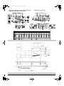
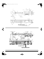
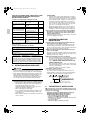
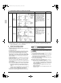
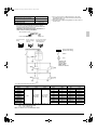
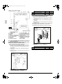
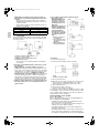
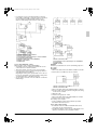
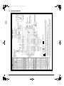
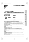
00_CV_3P034928-5P_1.fm Page 1 Wednesday, February 4, 2009 3:02 PM INSTALLATION MANUAL Total Heat Exchanger HRV (Heat Reclaim Ventilation) English Español MODELS (Ceiling mounted duct type) VAM150GJVE VAM250GJVE VAM350GJVE VAM500GJVE VAM650GJVE VAM800GJVE VAM1000GJVE VAM1500GJVE VAM2000GJVE Portugues Ðóññêèé HRV HRV;Heat Reclaim Ventilation Please read this installation manual carefully and install the unit properly to keep it at full capacity for a long time. Please provide some necessary parts, for example round hoods, air suction/discharge grilles etc., before the installation of the unit. HRV;Ventilación con recuperación de calor Por favor lea cuidadosamente el manual de instalacion e instale correctamente la unided para que pueda conservar su plena capacidad durante un largo periodo. Por favor, antes de proceder a la instalacion de la unidad, proporcione las piezas necesarias, por ejemple tapas redondas, rejillas de aspiracion y de impulsion de aire, etc. HRV;Ventilação de Recuperação Térmica Leia atentamente este manual e instale correctamente esta unidade para que esta funcione inteiramente durante um longo período de tempo. Adquira algumas peças necessárias, por exemplo, tampas redondas, grelhas de aspiração/exaustão, etc., antes da instalação da unidade. HRV;Вентиляция с реãенерацией тепла Внимательно ознаêомьтесь с данным рóêоводством и óстановите блоê надлежащим образом, чтобы он работал на полнóю мощность в течение долãоãо времени. Перед óстановêой блоêа подãотовьте необходимые детали, например êолпаê оêрóãлой формы, решетêи всасывания/выпóсêа воздóха и т.п HRV; Isý Geri Kazaným Vantilasyonu Uzun süreyle tam kapasitede muhafaza etmek için lütfen bu montaj kýlavuzunu dikkatle okuyun ve üniteyi doðru bir þekilde monte edin. Ünitenin montajýndan önce yuvarlak külahlar, hava emiþ/boþaltma ýzgaralarý vs. gibi bazý gerekli parçalarý lütfen temin edin. . 00_CV_3P034928-5P_2.fm Page 1 Wednesday, July 9, 2008 1:45 PM • VAM150GJVE, VAM250GJVE, VAM350GJVE, VAM500GJVE, VAM650GJVE, VAM800GJVE, VAM1000GJVE 1 1 4 2 5 9 7 10 2 200-300 3 650 or more 150-250 4 600 or more • VAM1500GJVE, VAM2000GJVE 3 5 7 10 8 11 8 11 6 9 12 6 13 2 12 4 2 15 16 13 14 4 14 Model name GJVE GJVE GJVE GJVE GJVE GJVE GJVE GJVE GJVE 1 2 [1] [mm] 00_CV_3P034928-5P_2.fm Page 2 Wednesday, July 9, 2008 1:45 PM 3 1 3 18 8 7 18 4 (φ350) 2 11 VAM2000GJVE 17 6 9 4 (φ250) 1 1 18 1 18 18 10 18 18 1 1 12 5 (φ250) 13 14 15 15 15 15 9 11 16 2500 or higher from the floor For installation in high places 16 2 Floor 4 [2] 01_En_3P034928-5P.fm Page 1 Thursday, February 5, 2009 2:43 PM VAM150GJVE VAM500GJVE VAM1000GJVE VAM250GJVE VAM650GJVE VAM1500GJVE VAM350GJVE VAM800GJVE VAM2000GJVE CONTENTS 1. 2. 3. 4. 5. 6. 7. 8. 9. 10. SAFETY PRECAUTIONS ............................................ 1 BEFORE INSTALLATION ............................................ 2 SELECTING INSTALLATION SITE ............................. 3 PREPARATIONS BEFORE INSTALLATION ............... 3 THE METHOD OF INSTALLATION ............................. 3 DUCT CONNECTION .................................................. 4 SYSTEM ...................................................................... 6 ELECTRIC WIRING WORK ......................................... 7 FIELD SETTING AND TEST RUN ............................. 12 DESCRIPTION OF SYSTEM AND APPLICABLE PATTERNS ................................ 14 11. WIRING DIAGRAM .................................................... 19 1. SAFETY PRECAUTIONS Please read these “SAFETY PRECAUTIONS” carefully before installing HRV and be sure to install it correctly. After completing installation, conduct a trial operation to check for faults and explain to the customer how to operate the air conditioner and take care of it with the aid of the operation manual. Ask the customer to store the installation manual along with the operation manual for future reference. This HRV comes under the term “appliances not accessible to the general public”. Meaning of WARNING and CAUTION notices. WARNING ..............Failure to follow these instructions properly may result in personal injury or loss of life. CAUTION ...............Failure to observe these instructions properly may result in property damage or personal injury, which may be serious depending on the circumstances. WARNING • Ask your dealer or qualified personnel to carry out installation work. Do not attempt to install the air conditioner yourself. Improper installation may result in water leakage, electric shocks or fire. • Installation should be done following the installation manual and no changes should be made to the unit. Improper installation may result in water leakage, electric shocks or fire. Injuries may result if the HRV falls. • Install the unit on a foundation strong enough to withstand the weight of the unit. A foundation of insufficient strength may result in the equipment falling and causing injuries. • Do not allow exhaust air to enter the outside air intake vent. This may cause the air of the room to become contaminated, harming the health. • Locate the outside air intake vent so that it does not take in exhaust air which contains combustion air, etc. Incorrect installation may cause a loss of oxygen in the room, leading to serious accidents. • Make sure that a separate power supply circuit is provided for this unit and that all electrical work is carried out by qualified personnel according to local laws and regulations and this installation manual. An insufficient power supply capacity or improper electrical construction may lead to electric shocks or fire. Insufficient power supply capacity or incorrect wiring may cause electrical shocks or fire. 1 Total Heat Exchanger HRV (Heat Reclaim Ventilation) Installation manual • Be sure to use only the specified accessories and parts for installation work. Failure to use the specified parts may result in the unit falling, water leakage, electric shocks or fire. • Carry out the specified installation work after taking into account strong winds, typhoons or earthquakes. Failure to do so during installation work may result in the unit falling and causing accidents. • Make sure that all wiring is secured, the specified wires are used, and that there is no strain on the terminal connections or wires. Improper connections or securing of wires may result in abnormal heat build-up or fire. • When wiring the power supply and connecting the remote controller wiring and transmission wiring, position the wires so that the control box lid can be securely fastened. Improper positioning of the control box lid may result in electric shocks, fire or the terminals overheating. • Be sure to switch off the unit before touching any electrical parts. • Be sure to earth the HRV. Do not earth the unit to a utility pipe, lightning conductor or telephone earth lead. Imperfect earthing may result in electric shocks or fire. A high surge current from lightning or other sources may cause damage to the air conditioner. • Be sure to install an earth leakage breaker. Failure to install an earth leakage breaker may result in electric shocks or fire. CAUTION • Install the indoor and outdoor units, power cord and connecting wires at least 1 meter away from televisions or radios to prevent picture interference and noise. (Depending on the incoming signal strength, a distance of 1 meter may not be sufficient to eliminate noise.) • Install the two outdoor ducts with down slope to prevent rainwater from entering the unit. If this is not done completely, water may enter the building, may damage furniture, and cause electric shocks and fire. • Insulate the two outdoor ducts and the supply air duct to prevent condensation. If this is not done completely, water may enter the building, may damage furniture, etc. • Insulate the duct and the wall electrically when a metal duct is to be penetrated through the metal lattice and wire lattice or metal lining of a wooden structure wall. Improper duct work may cause electric shocks or fire. • Do not install the unit in the following locations: 1. Place subjected to high temperature or direct flame. May result in fire or overheating. 2. Where there is a high concentration of mineral oil spray or vapour (e.g. a kitchen). This may cause fire. 3. Place such as machinery plant and chemical plant where gas, which contains noxious gas or corrosive components of materials such as acid, alkali organic solvent and paint, is generated. Place where combustible gas leakage is likely. Copper piping and brazed joints may corrode, causing refrigerant to leak or poisoning and fire due to leaked gas. 4. Near machinery emitting electromagnetic radiation. Electromagnetic radiation may disturb the operation of the control system and result in a malfunction of the unit. English 01_En_3P034928-5P.fm Page 2 Thursday, February 5, 2009 2:43 PM • • • • 2. 5. Where flammable gas may leak, where there is carbon fibre or ignitable dust suspensions in the air, or where volatile flammables such as paint thinner or gasoline are handled. Operating the unit in such conditions may result in fire. The HRV is not intended for use in a potentially explosive atmosphere. Make sure the temperature and humidity near the unit and the air suction/discharge air grille is within limit dictated by the usage conditions. 1. Refrigerated truck or other locations with low temperatures. 2. Place such as bathroom or heated pools subjected to moisture. This may cause fires or electric leak or electric shocks. Make sure that a snow protection measure is taken. If no protection snow may enter through the outdoor ducts, and cause damaging furniture and electric shock and fire. In areas where insects are easily attracted to a light, such as where there is a window or light near a ventilation opening, extremely small insects can sometimes infiltrate the room by passing through the ventilation opening. Since totally preventing against infiltration by extremely small insects is difficult, it is important to consider a serious solution like a filter box (field supply) during the design process to protect against insect infiltration. BEFORE INSTALLATION The accessories needed for installation must be retained in your custody until the installation work is completed. Do not discard them! 1. Decide upon a line of transport. 2. Leave the unit inside its packaging while moving, until reaching the installation site. Where unpacking is unavoidable, use a sling of soft material or protective plates together with a rope when lifting, to avoid damage or scratches to the unit. Hold the unit by the hanger brackets (4) when opening the crate and moving it, and do not lift it holding on to any other part (especially the duct connecting flange). 2-1 PRECAUTIONS • Be sure to instruct customers how to properly operate the unit (especially maintenance of air filter, and operation procedure) by having them carry out operations themselves while looking at the manual. • Where the air contains high levels of salt such as that near the ocean and where voltage fluctuates greatly such as that in factories. Also in vehicles or vessels. 2-2 DIMENSIONS • See figure 1 1. Maintenance space for the heat exchange elements, the air filters, control box, and fans 2. Maintenance cover 3. Inspection hatch ( 450 mm) 4. Control box 5. Hanger bracket (14×40 mm oval hole) 6. Exhaust air fan 7. OA (Outdoor air) Fresh air from outdoors 8. EA (Exhaust air) Exhaust air to outdoors 9. Supply air fan 10. SA (Supply air) Supply air to room 11. RA (Return air) Return air from room 12. Damper 13. Heat exchange elements 14. Air filters 15. Applicable duct 16. Nominal diameter à English [mm] Model name Weight (kg) Applicable nominal diameters of ducts VAM150GJVE 24 φ100 VAM250GJVE 24 φ150 VAM350GJVE 32 φ150 VAM500GJVE 32 φ200 VAM650GJVE 45 φ200 VAM800GJVE 55 φ250 VAM1000GJVE 67 φ250 VAM1500GJVE 129 φ350 VAM2000GJVE 157 φ350 2-3 ACCESSORIES Check the following accessories are included with your unit. Name Duct connecting flange Quantity 4 pcs. M4 tapping screw Harness for (For connecting external damper duct) operation Refer to Table 1 1 pc. Shape Name Clamp Quantity 3 pcs. Shape • • • (Other) Installation manual Operation manual Warranty Table 1 Quantity of tapping screw Model name Quantity VAM150GJVE, 250GJVE, 350GJVE, 500GJVE 16 pcs. VAM650GJVE, 800GJVE, 1000GJVE, 1500GJVE, 24 pcs. 2000GJVE 2-4 OPTIONAL ACCESSORIES • This unit can be made a part of different systems: as part of the combined operation system used together with VRV SYSTEM Air Conditioners, and as the independent system using only the HRV. An operating remote controller is required for this unit when using the unit as an independent system. Select a suitable remote controller from below table according to customer request and technical materials. Table 2 Remote controller type Combined operation system BRC1A61, 62, BRC1C61 Independent system BRC301B61 NOTE) 1 If you use the remote controller which is not listed in above table, please consult your dealer. NOTE) 2 We recommend the remote controller “BRC1C61” or “BRC301B61”. Because it displays the ventilation mode and can be selected ventilation fan mode with the button. NOTE) 3 The remote controller “BRC301B61” can be used by sub remote controller when using the unit as combined operation system. • When installing the unit, have ready the round shape hood, the air discharge grille and the air suction grille, and other parts needed for the installation. Consult your Daikin dealer when selecting optional accessories. 2 01_En_3P034928-5P.fm Page 3 Thursday, February 5, 2009 2:43 PM FOR THE FOLLOWING ITEMS, TAKE SPECIAL CARE DURING CONSTRUCTION AND CHECK AFTER INSTALLATION IS FINISHED. a. Items to be checked after completion of work Items to be checked If not properly done, what is likely to occur Check Is the outdoor duct installed Penetration of rain water to outside with down may drip. slope? Is the unit fully insulated? Condensate water may drip. Dose the power supply voltage correspond to that shown on the name plate? The unit may malfunction or the components burn out. Are wiring correct? The unit may malfunction or the components burn out. Is the unit safely grounded? Dangerous at electric leakage. Is wiring size according to specifications? The unit may malfunction or the components burn out. 4. It may result in insufficient Is something blocking the ventilation or unusual operair outlet or inlet of the unit? ating noise. Please check all items listed in the “SAFETY PRECAUTIONS” above once again. b. Items to be checked at time of delivery Items to be checked Check Did you explain about operations while showing the operation manual to your customer? Did you hand the operation manual and warranty over to your customer? c. Points for explanation about operations The items with WARNING and CAUTION marks in the operation manual are the items pertaining to possibillties for bodily injury and material damage in addition to the general usage of the product. Accordingly, it is necessary that you make a full explanation about the described contents and also ask your customers to read the operation manual. 3. SELECTING INSTALLATION SITE CAUTION • When moving the unit during or after unpacking, make sure to lift it by holding its hanger brackets. Do not exert any pressure on other parts, especially duct connecting flange. • Please attach additional thermal insulation material to the unit body when it is believed that the temperature and the relative humidity in the ceiling exceed 30°C and 80%. Use glass wool, polyethylene foam, or similar with a thickness of 10 mm or more as thermal insulation material. (1)Select an installation site where the following conditions are fulfilled and that meets with your customer’s approval. • Install in a place which has sufficient strength and stability. (Beams, ceiling, and other locations capable of fully supporting the weight of the unit.) Insufficient strength is dangerous. It may also cause vibration and unusual operating noise. • Where nothing blocks air passage. • Do not install the unit directly against a ceiling or wall. (If the unit is in contact with the ceiling or wall, it can cause vibration.) • Where sufficient clearance for maintenance and service can be ensured. 3 [PRECAUTION] • Install the units, power supply wiring and connecting wires at least 1 meter away from televisions or radios in order to prevent image interference or noise. (Depending on the radio waves, a distance of 1 meter may not be sufficient enough to eliminate the electric noise.) • The bellows may not be able to be used in some disctricts, so exercise caution. (Contact your local government office or fire department for details.) • When discharging exhaust air to a common duct, the Building Standard Law requires the use of fire-proof materials, so attach a 2m copper plate standing duct. (2)Use suspension bolts for installation. Check whether the ceiling is strong enough to support the weight of the unit or not. If there is a risk, reinforce the ceiling before installing the unit. (Installation pitch is mentioned as follow. Refer to it to check for points requiring reinforcing.) PREPARATIONS BEFORE INSTALLATION (1)Confirm the positional relationship between the unit and suspension bolts. (Refer to Fig. 1) Leave space for servicing the unit and include inspection hatches. (Always open a hole on the side of the electric parts box so that the air filters, heat exchange elements and fans can be easily inspected and serviced.) (2)Make sure the range of the unit’s external static pressure is not exceeded. (See the fan-strength and static performance characteristic drawings as well as the general catalog for the range of the external static pressure setting.) (3)Open the installation hole. (Pre-set ceilings) • Once the installation hole is opened in the ceiling where the unit is to be installed, pass transmission wiring, and remote controller wiring to the unit’s wiring holes. See “8. WIRING EXAMPLE AND HOW TO SET THE REMOTE CONTROLLER”. • After opening the ceiling hole, make sure ceiling is level if needed. It might be necessary to reinforce the ceiling frame to prevent shaking. Consult an architect or carpenter for details. (4)Install the suspension bolts. (Use M10 to M12 suspension bolts.) Use a hole-in-anchor, sunken insert, sunken anchor for existing ceilings, or other part to be procured in the field to reinforce the ceiling to bearing the weight of the unit. Ceiling slab Anchor bolt Long nut or turn-buckle Suspension bolt Unit Note: All the above parts are locally procured. 5. THE METHOD OF INSTALLATION 〈〈As for the parts to be used for installation work, be sure to use the provided accessories and specified parts designated by our company.〉〉 • Example of Installation, VAM500GJVE (See figure 2), VAM800GJVE (VAM1000GJVE) (See figure 3), VAM1500GJVE, VAM2000GJVE (See figure 4) 1. Air suction/discharge grille (field supply) 2. Inspection hatch ( 450 mm) (field supply) 3. Maintenance space for the heat exchange elements, air filters, control box and fans 4. Duct (field supply) 5. Duct (field supply) or flexible duct (option) à English 01_En_3P034928-5P.fm Page 4 Thursday, February 5, 2009 2:43 PM 6. Branch duct (field supply) or (only for VAM800GJVE~2000GJVE) 7. Flexible duct (option) 8. Silencer (option) 9. EA (Exhaust air to outdoors) 10. Heat insulator (field supply) 11. OA (Outdoor air) fresh air from outdoors 12. Metal suspension bracket for absorbing vibration (field supply) 13. Suspension bolt (field supply) 14. Gradient of down to outdoor ≥ 1/30 15. SA (Supply air to room) 16. RA (Return air from room) 17. Round hood (field supply) 18. Suspension bolt position <Cautions on installing the ducts> • The parts marked with* are effective in reducing blowing noise. • When using the unit at a quiet place, use the optional silencer box and flexible duct at the part of the air discharge outlet on the indoor side “SA” (supply air to room) of the unit, to counter the noise. • When selecting installation materials, consider the required volume of air flow and noise level in that particular installation. • When the outdoor air infiltrates into the ceiling and the temperature and humidity in the ceiling become high, insulate the metal portions of the unit. (1)Attach duct connecting flange <VAM150GJVE, VAM250GJVE, VAM350GJVE, VAM500GJVE> Attach the 4 included duct connecting flanges using the included screws. Match the symbol on the duct joints (the triangle on the flange) to the position marking on the unit when attaching. (2)Installing the main unit Pass hanger bracket over the bolts and secure with commercially available washers and nuts. (When installing the main unit, make sure there are no foreign objects (plastic, paper, etc.) inside the fan housing by looking inside through the duct hole before connecting the duct.) • When reversing the hanger brackets in order to install the unit upside down, be sure to secure them with the removed screws. • Attach the indoor (SA, RA) and outdoor (EA, OA) ducts by referring to the duct diagram on the name plate. <VAM150GJVE, VAM250GJVE, VAM350GJVE, VAM500GJVE, VAM650GJVE, VAM800GJVE, VAM1000GJVE> 1 2 3 4 <VAM1500GJVE, VAM2000GJVE> 1 2 3 4 1 1. Hanger bracket 2. Nut 3. Washer 4. Double nuts 2 3 3 6. DUCT CONNECTION <Perform duct work keeping the following things in mind> 1. Do not connect the ducts as shown below. 4 <VAM650GJVE, VAM800GJVE, VAM1000GJVE, VAM1500GJVE, VAM2000GJVE> Attach the 4 included duct joints using the included screws. (1) Exterme bend (Do not bend the duct over 90˚) (2) Multi bend (3) Reduce the diameter of the duct to be connected. (4) a bend right next to the outlet 1 (Do not reduce the duct diameter halfway.) 3 3 1. Screw 2. Duct joint symbol 3. Duct connecting flange 4. Unit position marking (RA has a φ3 indentation) Model Number of screw Model Number of screw VAM150GJVE 16 VAM800GJVE 24 VAM250GJVE 16 VAM1000GJVE 24 VAM350GJVE 16 VAM1500GJVE 24 VAM500GJVE 16 VAM2000GJVE 24 VAM650GJVE 24 English 2. The minimal radius of bends for flexible ducts are as follows. 100 mm diameter duct : 100 mm 150 mm diameter duct : 150 mm 200 mm diameter duct : 300 mm 250 mm diameter duct : 375 mm 3. To prevent air leakage, wind aluminum tape round the section after the duct connecting flange and the duct are connected. (Refer to Fig. below) 4. To prevent air leakage install the opening of the indoor air intake as far as from the opening of the exhaust suction. 5. Use the duct applicable to the model of unit used (Refer to the outline drawing.) 6. Install the two outdoor ducts with down slope (slope of 1/30 or more) to prevent entry of rain water. Also, provide insulation for both ducts to prevent dew formation. (Material : Glass wool of 25mm thick) If the unit is going to be used in cold places where the outside temperature reaches –10°C or below, insulate the indoor ducts as well. 4 01_En_3P034928-5P.fm Page 5 Thursday, February 5, 2009 2:43 PM 7. If the level of temperature and humidity inside the ceiling is always high, install a ventilation equipment inside the ceiling. 8. Insulate the duct and the wall electrically when a metal duct is to be penetrated through the metal lattice and wire lattice or metal lining of a wooden structure wall. 9. Using flexible or silent ducts can be effective in reducing the air discharge sound of the supply air to room (SA). Select materials keeping in mind the fan strength and operating sound of the unit. Consult your Daikin dealer for selection. 10. Set the pitch between the exhaust air outlet (EA) and the outside air intake (OA) to at least 3 times the duct diameter. 11. Do not use a bent cap or a round hood as the outdoor hood if they might get rained on directly. (We recommend using a deep hood (optional accessory).) 12. When using a deep hood, make sure the duct from the deep hood (outer wall) to the unit is at least 1m long. (3) When attaching muffling boxes (Option), attach them to the upper and lower SA (Supply air). 3 5 6 6 4 3 1. Connection chamber 2. Wind direction slats 3. Duct adapter (Option) 4. Silencer (Option) 5. SA (Supply air) 6. RA (Return air) • Attachment of the ducts should be done after the unit has been transported (i.e. using a lifter, etc.). (Do not transport the machine by holding the duct joints or duct adapters.) • This product has a very strong fan strength, so we recommend using a muffling box (Option), flexible duct (Option), thin intake/outlet grille (Option), or other items in order to reduce the noise of the air being blown. • See our general catalog (for designers and engineers) for items which are options. Select the proper materials taking fan strength and noise levels into consideration before installation. 1. Aluminium tape (field supply) 2. Insulation material (field supply) 3. Duct connecting flange (option) 4. Slope over 1/30 5. OA (Outdoor air) Fresh air from outdoors 6. EA (Exhaust air to outdoors) 7. Suspension bolt (field supply) 8. Metal suspension bracket for absorbing vibration (field supply) WHEN USING ROUND φ250 DUCTS FOR SA (SUPPLY AIR) AND RA (RETURN AIR) (φ350 → φ250 × 2) (1) Remove the 4 installation screws and then the indoor connection chamber.Remove the 4 installation screws and then the wind direction slats. INTRODUCING THE SILENCERS AND OTHER OPTIONS. This model handles a high air flow rate. To reduce the blow-out noise, some optional attachments are available silencer, flexible duct, thin air intake/exhaust grille, etc. Remove the connection chamber off the SA (Supply air) side and attach the upper and lower silencers. Fix the duct connecting flanges (Option) and connect the 250 mm dia. flexible ducts. USING A HIGH-EFFICIENCY FILTER (OPTION) • Replace the high-efficiency filter around once a year. • Replace more often when used in heavily polluted locations. (The high-efficiency filter is option.) (1)Remove the maintenance cover. 1 2 (2)Attach the high-efficiency filter. Make sure it is attached in the correct location. 2 4 1 3 1 (2) Attach the duct adapter (Option) depending on the included screws. 3 5 5 6 6 6 6 Attach along the inside of the rails. 2 3 5 1. Maintenance cover 2. High-efficiency filter 3. Control box 4. Heat exchanger element 5. Air filter 6. Rails (3)Attach the maintenance cover. English 01_En_3P034928-5P.fm Page 6 Thursday, February 5, 2009 2:43 PM 7. SYSTEM 7-1 Independent system Air conditioner linked operation system SYSTEM Independent system 1-group linked operation system Standard method Related items in Electric wiring • Up to 16 units can be controlled with the remote controller for HRV. (A system with two remote controls can be created in the master/slave switching.) • All HRV operations can be used and indicated. • Operation monitor output and humidifier operation are possible using Adapter PCB. • Remote control cord should be procured locally. (Maximum cord length : 500 m) 9-2-1 • A combined total of up to 16 air conditioners and the HRV can be controlled. • The HRV ventilation mode can be operated independently when air conditioners are not being used. • Using the local setting of the remote controller for air conditioners, various settings such as pre-cool/pre-heat reservation on/off, ventilation flow rate, ventilation mode, etc. 9-3-1 • Since all VRV units are connected to a single line in view of installation, all VRV units are subjects for operation. • If there are problems operating all VRV units, do not use this system. Combined operation system with VRV systems and Sky-air series Multi-group (2 or more) linked operation system 9-3-3 NOTES (1) Adapter PCB : KPR50-2 ; Distant control adapter : KRP2A62 : Installation box for adapter PCB : KRP50-2A90 (2) Operation of two or more group is not possible with direct duct connection. (3) With VAM types, the direct duct connection shown can also be selected for 1-group operation systems. SYSTEM Direct duct connection system English Standard method • The HRV will operate only when the air conditioner fan is on. • When the air conditioner is not being used, the HRV can be operated in circulation or ventilation modes. • Other specifications are the same as those of the standard system. Related items in Electric wiring 9-3-2 6 01_En_3P034928-5P.fm Page 7 Thursday, February 5, 2009 2:43 PM 7-2 CENTRALIZED CONTROL SYSTEM (VRV SYSTEM) SYSTEM “All”/individual control system Centralized control system Zone control system Standard method • Use of the on/off controller, Adapter PCB for remote control or schedule timer enables centralized control of the entire system. (maximum of 64 groups) • The on/off controller can turn on or off the individual units. • The schedule timer and on/off controller can be used together. However, the Adapter PCB for remote control cannot be used with another centralized control device. • Use of the centralized controller enables zone control via the centralized control line. (maximum of 64 zones) • The central controller displays the “Filter” indication and abnormality warnings, and enables resetting. • The centralized controller allows ventilation operation for each zone independently. Related items in Electric wiring 9-4-2 9-4-3 [Caution] (1) Wiring adapter for remote contact : KRP50-2, Adapter PCB for remote control KRP2A62, schedule timer DST30B61, on/off controller. DCS301B61, controller: DCS302B61 8. ELECTRIC WIRING WORK • Shut off the power before doing any work. • All field supplied parts and materials, electric works must conform to local codes. • Use copper wire only. • All wiring must be performed by an authorized electrician. • See also the “Electrical Wiring Diagram label” attached to the electric parts box lid when laying electrical wiring. • Wire the remote controller as shown in the electric wiring diagram label. See the “Remote Controller Installation Manual” for details on how to install and lay the wiring for the remote controller. • Install a wiring interrupter or ground-fault circuit interrupter for the power wiring. • Make sure the ground resistance is no greater than 100Ω . This value can be as high as 500Ω when using a ground fault circuit interrupter since the protective ground resistance can be applied. • Do no let the ground wire should come in contact with gas pipes, water pipes, lighting rods, or telephone ground wires. • Gas pipes: gas leaks can cause explosions and fire. • Water pipes: cannot be grounded if hard vinyl pipes are used. • Telephone ground and lightning rods: the ground potential when struck by lightning gets extremely high. • Do not turn on the power supply (wiring interrupter or ground-fault circuit interrupter) until all other work is done. 7 CAUTION Before obtaining access to terminal devices, all power supply circuits must be interrupted. 8-1 PRECAUTIONS WHEN LAYING POWER SUPPLY WIRING [PRECAUTION] 1. A circuit breaker capable of shutting down power supply to the entire system must be installed. 2. A single switch can be used to supply power to units on the same system. However, branch switches and branch circuit breakers must be selected carefully. 3. Fit the power supply wiring of each unit with a switch and fuse as shown in the drawing. 4. Be sure to give the electric grounding (earth) connection. 5. Tightening torque for the terminal screws. • Use the correct screwdriver for tightening the terminal screws. If the blade of screwdriver is too small, the head of the screw might be damaged, and the screw will not be properly tightened. • If the terminal screws are tightened too hard, screws might be damaged. • Refer to the table below for the tightening torque of the terminal screws. English 01_En_3P034928-5P.fm Page 8 Thursday, February 5, 2009 2:43 PM Tightening torque (N·m) Treminal block for remote controller/ Transmission wiring (X2M) 0.79 – 0.97 Power supply terminal block (X1M) 1.18 – 1.44 Ground terminal (M4) 1.44 – 1.94 7. Do not connect wires of different gauge to the same grounding terminal. Looseness in the connection may deteriorate protection. 8. Keep the power supply wiring distant from other wires to prevent noise. 6. Connect round crimp-style terminals provided with insulation sleeves to the terminal block for power supply. Be sure to follow the instructions provided below if the specified terminals cannot be used. Otherwise, abnormal heat may be generated as a result of the loosening of the wires. Attach insulation sleeve Round crimp-style terminal Connect the wires evenly. Electric wire Do not connect a wire to the single side only. Do not connect wires different from each other in diameter. Power supply wiring Transmission wiring Switch Fuse 1. Outdoor unit 2. Indoor unit 3. Power supply 4. Main switch 5. Remote controller 1. Component electrical specifications Units Model Power supply MFA KW FLA VAM150G 0.9 15 0.03 × 2 0.4 × 2 VAM250G 0.9 15 0.03 × 2 0.4 × 2 VAM350G 1.35 15 0.09 × 2 0.6 × 2 VAM500G 1.35 15 0.09 × 2 0.6 × 2 2.3 15 0.14 × 2 1.0 × 2 3.4 15 0.28 × 2 1.5 × 2 VAM800G JVE 50Hz Power supply Max.264V Min.198V 60Hz Fan motor MCA VAM650G Type Power supply Max.242V Min.198V VAM1000G 3.4 15 0.28 × 2 1.5 × 2 VAM1500G 6.75 15 0.28 × 4 1.5 × 4 VAM2000G 6.75 15 0.28 × 4 1.5 × 4 Symbol) MCA: Min. Circuit Amps (A) MFA: Max. Fuse Amps (A) KW: Motor Rated Output (kW) FLA: Full Load Amps (A) NOTE: For details, refer to ELECTRICAL DATA. English 8 01_En_3P034928-5P.fm Page 9 Thursday, February 5, 2009 2:43 PM 2. Specifications for field supplied fuses and wire Model Type Power supply Transmission wiring Field supplied fuses Wire Size Wire Size 15A H05VV-U3G Wire size must comply with local codes Shield wire (2 wire) 0.75-1.25 mm2 VAM150G VAM250G VAM350G VAM500G VAM650G JVE VAM800G VAM1000G VAM1500G VAM2000G NOTES 1. If the wiring is in a place where people it can be easily touched by people, install a leak interrupter to prevent electric shock. 2. When using a ground-fault circuit interrupter, make sure to select one useful also to protection against overcurrent and short-circuit. If you use a leak interrupter which is designed for protecting again ground faults, be sure to combine it with a wiring interrupter or an load switch that has a fuse. 3. The length of the transmission wiring and remote controller wiring are as follows. • Length of outdoor-indoor transmission wiring … max 1000m (total wiring length 2000m) • Length of remote controller wiring between indoor unit and remote controller … max 500m 8-2 WIRING EXAMPLE CAUTION Before opening the cover, be sure to turn off the power switches of the main units and other devices connected with the main units. 1. Remove the screw securing the cover and open the control box. 2. Secure the power cord control wires with the clamp, as shown in 8-2.2.(3) • Opening and shutting the control box and connecting the wiring (1) Always shut off the power before opening the control box lid. (2) Remove the 2 attachment screws on the control box lid as shown below and then open the lid. <VAM150GJVE, VAM250GJVE, VAM350GJVE, VAM500GJVE, VAM800GJVE, VAM1000GJVE> Control box Installation screws Power wiring Wiring through-hole CAUTION If, after doing the wiring, there is a gap between the wiring and the wiring through-hole, fill it in to avoid insects and small animals crawling in. <VAM1500GJVE, VAM2000GJVE> Move Open Installation screws Close Wiring through-hole Control box lid CAUTION If, after doing the wiring, there is a gap between the wiring and the wiring through-hole, fill it in to avoid insects and small animals crawling in. (3) Pass all power, ground, and branch wiring (the signaler and the remote control wiring) through the hole in the control box, connect all the wires to the appropriate terminals, and secure them with the clamping material. NOTES If you are installing the adapter circuit board, the adapter circuit board installation box (sold separately) is needed. See the manual that came with the adapter circuit board installation box on how to install it. <VAM150GJVE, VAM250GJVE, VAM350GJVE, VAM500GJVE, VAM800GJVE, VAM1000GJVE> Power terminal block Ground terminal (M4 screw + spring lock washer + flat washer + cup washer) • This is for connecting the power wiring. Control box Power wiring Ground wire Terminal block (X2M) For branch wiring (signaler, remote control cord, and connection terminal block) Clamping material (included) Clamping material (included) (For power and ground wiring) Power wiring through-hole Clamping material (included) For branch wiring (signaler and remote control cord) Clamping material (included) Wiring 9 Circuit board L N Remote Centralized No-volt external input control LCD remote control (sold separately) Condition when shipped from factory Do not change the switch settings. SS1 is the switch for setting the remote control. Changing the settings will prevent normal functioning. English 01_En_3P034928-5P.fm Page 10 Thursday, February 5, 2009 2:43 PM <VAM1500GJVE, VAM2000GJVE> Round crimp-style terminal Condition when shipped from factory Cup washer Spring washer, flat washer Terminal block (X2M) For branch wiring (signaler, remote control cord, and connection terminal block) Do not change the switch settings. SS1 is the switch for setting the remote control. Changing the settings will prevent normal functioning. Remote Centralized No-volt external input control LCD remote control (sold separately) Power terminal block • This is for connecting the power wiring. L N Terminal block (X2M) For branch wiring (signaler, remote control cord, and connection terminal block) Branch wiring Ground terminal (M4 screw + spring lock washer + flat washer + cup washer) Clamping material (included) Power and ground wiring Clamping material (included) Power wiring Ground wire Clampingmaterial (included) (4) When closing the control box lid CAUTION • Use an appropriate screwdriver for tightening the terminal screws. A screwdriver with a small head will strip the head and make proper tightening impossible. Over-tightening the terminal screws may break them. See the following table for the tightening torque of the terminal screws. • X2M terminal block (M3.5): 0.79~0.97 N · m • Ground terminal (M4): 1.18~1.44N · m • X1M terminal block (M4): 1.44~1.94 N · m Ground screw Cut out section 4. Be sure to connect the remote control wiring and the transmission wiring to the terminals on the X2M terminal block. [PRECAUTIONS] • Refer to the “Remote Controller Installation Manual” on how to install and lay the wiring for the remote controller. • Do not, under any circumstances, connect the power wiring to the remote controller or transmission wiring terminal block. Doing so can destroy the entire system. • Connect the remote controller and transmission wiring their respective terminal blocks. • All transmission wiring except for the remote controller wires is polarized and must match the terminal symbol. • Use shield wire in transmission wiring. Ground the shield of the shield wire to “ ”, at the grounding screw, with the Ccup washer. • Sheathed wire materials may be used for transmission wiring, but they are not suitable for EMC (Electromagnetic Compatibility) (European Directive). When using sheathed wire, electromagnetic Compatibility must conform to Japanese standards stipulated in the Electric Appliance Regulatory Act. Transmission wiring need not be grounded when using sheathed wire. 8-3 Power cord connection, control wire terminals and switches on the electronic control unit (Printed circuit board) • Connect the power cord to the L and N terminals. • Secure the power cord with the power cord clamp. • Be sure to give the electric grounding (earth) connection. <VAM150GJVE, VAM250GJVE, VAM350GJVE, VAM500GJVE, VAM650GJVE, VAM800GJVE, VAM1000GJVE> CAUTION • Be sure to attach the sealing material or putty (locally procured) to hole of wiring to prevent the infiltration of water as well as any insects and other small creatures from outside. Otherwise a short-circuit may occur inside the electric parts box. • When clamping the wires, be sure no pressure is applied to the wire connections by using the included clamping material to make appropriate clamps. Also, when wiring, make sure the lid on the electric parts box fits snugly by arranging the wires neatly and attaching the electric parts box lid firmly. When attaching the electric parts box lid, make sure no wires get caught in the edges. Pass wiring through the wiring through holes to prevent damage to them. • Make sure the remote controller wiring, the wiring between the units, and other electrical wiring do not pass through the same locations outside of the unit, separating them by at least 50mm, otherwise electrical noise (external static) could cause mistaken operation or breakage. L N 3. Be sure to connect the ground wire. 〈Precautions when connecting the ground〉 When pulling the ground wire out, wire it so that it comes through the cut out section of the cup washer. (An improper ground connection may prevent a good ground from being achieved.) English 10 01_En_3P034928-5P.fm Page 11 Thursday, February 5, 2009 2:43 PM <VAM1500GJVE, VAM2000GJVE> Applicable adapter name Kit name Fixing box A Adapter PCB for Humidifier KRP50-2 KRP50-2A90 B Adapter PCB Remore controller KRP2A62 KRP50-2A90 <VAM1500GJVE, VAM2000GJVE> • When install the optional adaptor circuit board, it is necessary to prepare the fixing box (KRP50-2A90) 1. Open the electrical compartment cover by following the procedure described in the “8-2 Opening the control box” section. 2. Remove the securing screw, and install the adapter circuit board. 3. After the wires are connected, fasten the electrical compartment cover. • The adapter circuit board (KRP50-2) can be installed on the inner right-hand side of the electric component box. The attachment box (optional accessory) is not required. L N 1. Tranformer 2. Secondary 3. Primary 4. Connector for supply air fan 5. Connector for exhaust air fan 6. Connector for damper 7. Power supply 8. Terminals 9. Connector for KPR50-2 10. Connector for damper 11. Connector for indoor air thermistor 12. Connector for outdoor air thermistor 13. Selector switch 14. Terminal port for remote controller 15. Terminal port for centralized control 16. Terminal port for no-voltage external input 17. Factory setting 1 3 A 2 B 2 5 8-4 How to install the optional adapter circuit board (KRP2A62, KRP50-2) <VAM150GJVE, VAM250GJVE, VAM350GJVE, VAM500GJVE, VAM650GJVE, VAM800GJVE, VAM1000GJVE> • When install the optional adaptor circuit board, it is necessary to prepare the fixing box (KRP50-2A90) 1. Open the electrical compartment cover by following the procedure described in the “8-2 Opening the control box” section. 2. Remove the securing screw, and install the adapter circuit board. 3. After the wires are connected, fasten the electrical compartment cover. 1. Fixing board 2. PCB support (Attached to adapter PCB) 11 3 4 1. Fixing board 2. PCB support (Attached to adapter PCB) 3. Fixing screw 4. Lid 5. Control box Applicable adapter name Kit name A Adapter PCB for Humidifier KRP50-2 B Adapter PCB Remore controller KRP2A62 Fixing box KRP50-2A90 3. Fixing screw 4. Lid 5. Control box English 01_En_3P034928-5P.fm Page 12 Thursday, February 5, 2009 2:43 PM 9. FIELD SETTING AND TEST RUN 9-1 Make sure the electric parts box lids are closed on the indoor and outdoor units. 9-2 Depending on the type of installation, make the field settings from the remote controller after the power is turned on, following the “Field Settings” manual which came with the remote controller. Lastly, make sure the customer keeps the “Field Settings” manual, along with the operating manual, in a safe place. SECOND CODE NO. FIRST CODE NO. Mode No. SETTING FIELD SET MODE Local setting Using the remote controller of the VRV-system air conditioner to make HRV unit settings (1) Initial setting (1) Mode nos. 17,18 and 19: Group control of HRV units. (2) Mode nos. 27, 28 and 29: individual control Operating procedure The following describes the operating procedure and settings. (1) Press the INSPECTION/TRIAL button for more than four seconds with the unit in the normal mode to enter the local setting mode. (2) Use the TEMPERATURE ADJUSTMENT button to select the desired “mode number.” (The code display will blink.) (3) To make settings for individual units under group control (when mode No. 27, 28 or 29 is selected), press the TIMER SETTING ON/OFF button to select the “unit No.” for which the settings are to be made. (This process is not necessary when settings are made for the entire group.) (4) Press the top section of the TIMER button to select the “setting switch No.” (5) Press the lower section of the TIMER button to select “setting position No.” (6) Press the PROGRAM/CANCEL button once to enter the settings. (The code display will stop blinking and light up.) (7) Press the INSPECTION/TRIAL button to return to normal mode. <Example> When adjusting the ventilation air flow to low setting in the group setting mode, enter the mode No., “19” setting switch No., “0” and setting position No., “01”. SETTING Remote controller for HRV BRC301B61 English 12 01_En_3P034928-5P.fm Page 13 Thursday, February 5, 2009 2:43 PM List of Settings Mode No. Group settings 17 Setting Individual switch No. settings 19 29 Approx. Approx. 2500 hours 1250 hours 03 04 05 06 No counting – – – 4 hours 6 hours 8 hours – – 1 Nighttime free cooling operation start time (after other air conditioners operating together with the unit have been stopped) 2 Pre-cool/pre-heat on/off setting Off On – – – 3 Pre-cool/pre-heat time setting 30 min 45 min 60 min – – – 4 Fan speed initial setting Normal Ultra high – – – – Yes/No setting for direct duct connection with VRV system No duct (Air flow setting) With duct (fan off) – – – – Setting for cold areas (Fan operation selection for heater thermo OFF) – – Fan off Fan L Fan off Fan L Centralized Individual – – – – No Yes Priority on operation – – – 0 min 30 min 60 min 90 min – – – – – – 7 Centralized/individual setting 8 Centralized zone interlock setting 9 Pre-heat time extension setting Off 2 hours Last Priority on command external input No duct With duct 0 External signal JC/J2 1 Setting for direct Power ON Off On – – – – 2 Auto restart setting Off On – – – – 3 External damper operation – – On – – – 4 Indication of ventilation mode/Not indication Indication No Indication – – – – 7 Fresh up air supply/exhaust setting 8 No Indication No Indication Indication Supply Exhaust External input terminal fanction selection (between J1 and JC) Fresh-up Overall alarm 9 KRP50-2 output switching selection (between 1 and 3) Fan on/off Abnormal 0 Ventilation air flow setting Low 2 Ventilation mode setting Automatic 3 “Fresh Up” on/off setting Off 8 Electric heater setting No delay NOTE) 1. The setting positions within the bolded cells “ ” are factory default. The settings can be done either from the unit or from the HRV remote controller. 2. The settings are applied to the entire group, but if the mode no. inside the parentheses is selected, the settings can be applied to individual indoor units. However, it is only possible to check any changes made to the settings inside the parentheses in individual mode. (For group batch operation, the changes are made but the display remains as it was when shipped from the factory.) 3. Do not set anything not shown above. If the applicable functions are not available, they will not be displayed. 4. When returning to normal mode, the remote controller is initialized, so the display might show “88.” 5. Group number setting for centralized controller (1) Mode No. 00: Group controller (2) Mode No. 30: Individual controller * Regarding the setting procedure, refer to the section “Group number setting for centralized control” in the operating manual of either the on/off controller or the central controller. 13 02 Filter cleaning time setting 27 28 01 0 5 18 Setting position No. (NOTE 1) Description of Setting Supply Indication – – Exhaust – – Overall Fan forced Forced off malfunction off Air flow increase – – – – Low Low Low High High Exchange By pass – – – On – – – – Exchange On, off delay On, off delay – – 9-3 Perform a test run. (1) Before turn on the power supply, be sure to check it that the control box lid is closed. (2) Please perform a test run according to “OPERATION MANUAL”. • The operation lamp of the remote controller will flash when an malfunction occurs. Check the malfunction code on the liquid crystal display to identify the point of trouble. An explanation of malfunction codes and the corresponding trouble is provided in “OPERATION MANUAL”. If the display shows any of the following, there is a possibility that the wiring was done incorrectly or that the power is not on, so check again. Remote control display Content “ ” is display No display • Incorrect setting the MAIN/SUB switch of the remote controller. • The power on the indoor unit is off. • The indoor unit and HRV has not been wired for power supply. • Incorrect wiring for the remote controller wiring, the transmission wiring and / or the FORCED OFF wiring. • The remote controller wiring is cut. • Incorrect setting the “SS1” switch of PC board. English 01_En_3P034928-5P.fm Page 14 Thursday, February 5, 2009 2:43 PM 10. DESCRIPTION OF SYSTEM AND APPLICABLE PATTERNS 10-1 INDEPENDENT SYSTEM 10-1-1 When connecting to Remote controller for HRV (Refer to “Initial setting” under item “9-2 Local setting”.) Check the switches on the printed circuit board to the factory setting. SS1 Factory Setting NOR H M Do not change the switch settings. SS1 is a setting switch for special purposes. Changing the settings will stop the unit from operating normally. (2) Set the mode No. to “17” for group control, or “27” for individual control, the setting switch No. to “3” and the setting position No. to “03” Example 2: To switch the ventilation air flow to ultra high setting. (The units are set at the high air flow setting at the factory) Set the mode No. to “17” for group control, or “27” for individual control, the setting switch No. to “4” and the setting position No. to “02” Example 3: To switch the ventilation air flow to low setting. Set the mode No. to “19” for group control, or “29” for individual control, the setting switch No. to “0” and the setting position No. to “01” • Connecting the remote controller for HRV The remote controller for HRV cannot be used for starting/stopping operation or for timer operation. (The centralized control indication will be lit.) To set pre-cool/pre-heat function settings, change the remote control air flow rate setting from medium (M) to high (H), etc., perform initial settings from the remote controller for HRV. Since it will become a two-remote-control system, perform master/slave setting as shown below. Remote control 1. Master unit 4. Switch position : Master 2. Slave unit 5. Remote controller for HRV 3. Switch position : Slave 6. Maximum connection line length : 500m 10-2 Wiring and connections in combination with “VRV-SYSTEM” 10-2-1 Standard 1-group linked-control system • The remote control of the air conditioner can be used to control up to 16 air conditioner indoor units and HRV units. • Initial settings can be made for the functions of the HRV units (pre-cool/pre-heat, ventilation air flow, ventilation mode and “Fresh-Up”). Use the remote controller of the air conditioner to make the initial settings for the HRV units. Refer to “Initial setting” under Item “9-2 Local setting.” Master/slave setting Remote controller for air conditioner Slave Remote controller for HRV Master Refer to “preforming initial settings” in the remote control instruction manual. Example 4: To set the pre-cool/pre-heat reservation function to on and have the HRV start operating 60 minutes after the air conditioner has started, set the same numbers as shown in example 1 using the remote controller for HRV. Example 5: To increase the remote control air ventilation rate setting from Medium to High, set the same numbers as shown in example 2 using the remote controller for HRV. Air ventilation rate setting using remote control Default factory settings When set as in example 5 Low Low (L) air flow rate Low (L) air flow rate High Medium (M) air flow rate High (H) air flow rate 1. Remote controller for air conditioner 2. Remote controller for HRV 3. Connecting line can be extended up to 500m maximum English Default factory Setting SS1 Pre-cool/pre-heat function When the pre-cool/pre-heat function is set, the HRV unit switches on at the preset time (30, 45 or 60 minutes) after the VRV-system air conditioner begins cooling or heating operation. The function is set OFF at the factory. Therefore, to use this function, the initial setting must be made using the remote controller of the air conditioner. If the air conditioner is re-started within two hours after the operation was stopped, this function does not operate. Example 1: To switch on the pre-cool/pre-heat function, and turn on the HRV unit 60 minutes after the air conditioner is turned on. (1) Set the mode No. to “17” for group control, or “27” for individual control, the setting switch No. to “2” and the setting position No. to “02” NOR H M 1. Remote controller for air conditioner 2. Remote controller for HRV 3. Maximum connection line length : 500m 4. Medium (M) air flow rate 5. When the remote controller for HRV is connected, check the switches on the HRV unit PCB to the default factory settings. 14 01_En_3P034928-5P.fm Page 15 Thursday, February 5, 2009 2:43 PM • Determination of heating/cooling selection rights for VRV-systems is performed using the remote controller for HRV. The heating/cooling selection rights can be enabled or disabled using the ventilation mode button of the remote controller for HRV. This operation cannot be performed with the remote controller for air conditioner. Heating/cooling selection rights Operation switchover control display Enabled Not lit Disabled Lit Not set Blinking 10-2-2 Direct duct connection system for 1-group operation system Line connections and the settings of the switches on the HRV unit PCB should be the same as for “10-2-1 Standard system for 1-group system”. 1.Remote controller for air conditioner 2.Remote controller for HRV 3.Maximum connection line length : 500m 4.Medium (M) air flow rate Set the switches of the HRV unit PCB to the default factory settings. 1. Be sure to set the initial settings to Direct duct connection: Enabled. • When the remote contoroller for HRV is not yet connected, initial settings can be performed using the air conditioner remote control. Set the mode number to “17”, the setting switch number to “5”, and the setting position number to “02” according to the procedure in “1: Making local settings”. • When the remote contoroller for HRV, initial settings should be performed using the remote controller for HRV. Set the same numbers as described above when using the remote controller for air conditioner according to the procedure “Making initial settings” in the remote control instruction manual. 2. Settings for other HRV functions should be made using the same method as in “10-2-1 Standard system for 1group system”. 10-2-3 Linked control with more than two groups • Mount the optional KRP2A62 Adapter PCB for remote control on the electric component mounting base of one HRV unit. • A maximum of 64 air conditioners and HRV units can be connected to the F1 and F2 terminals. • Use the remote controller of the air conditioner to make the initial settings. 1. Remote controller for air conditioner 2. Connecting line can be extended up to 1000 m maximum 3. Optional distant control adapter KRP2A62 <Procedure> 1. Turn off the main power. 2. Connect the air-conditioner remote controller. 1. Remote controller for air conditioner 2. Remote controller for HRV 3. Turn on the main power. 4. Make the remote controller settings on site; Set the collective zone interlock to ON. Mode number “17”, setting switch number “8” and setting position number “02”. 5. Turn off the main power. 6. Disconnect the remote controller. Now the on-site settings are complete. For raising the remote-controlled ventilation air flow rate “High” to “Ultra-High”, connect the remote controller for the air conditioner to HRV and make settings on site. (Refer to “Initial setting” under item “9-2 Local setting”.) 10-3 Centralized control system 10-3-1 “All” control When using Adapter PCB for remote control (KRP2A61, 62, 63) or schedule timer (DST301B61) • A maximum of 64 air conditioners and HRV units can be connected to the F1 and F2 terminals. • This system does not required group number setting for centralized control. (auto-address system) • The Adapter PCB for remote control and schedule timer cannot be used together. • The Adapter PCB for remote control can be mounted on the electric component mounting base of either the HRV unit or air conditioner. (The HRV unit can accept only the KRP2A62.) 15 English 01_En_3P034928-5P.fm Page 16 Thursday, February 5, 2009 2:43 PM • For raising the remote-controlled ventilation air flow rate from “High” to “Ultra-High”, connect the remote controller for the air-conditioner to HRV and make settings on site. (Refer to “Initial setting” under item “9-2 Local setting”.) 1. Remote controller for air conditioner 2. Remote controller for HRV 3. Connecting line can be extended up to 1000 m maximum 4. Schedule timer (DST301B61) 5. Adapter PCB for remote control (KRP2A62) 6. Distant control adapter 7. On/Off signal 10-3-2 “All”/“individual” control When using the on/off controller (DCS301B61) • A maximum of 64 air conditioners and HRV units can be connected to the F1 and F2 terminals. • This system allows connection of four on/off controllers. • It is necessary to assign a central control group number to each HRV unit and air conditioner. Regarding the setting of the group number, refer to the section on “the centralized control group number setting” in the operating instructions of the On/off controller. • Use the remote controller of the air conditioner to make the initial settings. 1. Remote controller for air conditioner 2. Remote controller for HRV 3. Connecting line can be extended up to 1000 m maximum 4. Schedule timer 5. On/Off controller Example: Follow the procedure below to set the centralized group No. 205 to HRV 1. Procedure 1. Turn off the main switch of the HRV-1 and On/off controller. 2. Connect the air conditioner’s remote controller. 1. Remote controller for air conditioner 2. Remote controller for HRV 3. Turn on the main switch of the HRV-l and On/off controller. 4. Set the central control group number using the local setting on the remote controller. 5. Mode No.: “00” 6. Central control group No.: “2-05” 7. Turn off the main switch of the HRV and On/off controller. 8. Disconnect the remote controller. The setting is now complete. • For the ventilation air flow setting, follow the procedure described in the 10-3-1 section. 10-3-3 Zone control system • A maximum of 64 air conditioners and HRV units can be connected to the F1 and F2 terminals. • The HRV units will turn on and off in according with the zone operation command from the centralized controller. English 16 01_En_3P034928-5P.fm Page 17 Thursday, February 5, 2009 2:43 PM Zone 2 The HRV units operate in the zone-linked mode, as described in the section, “10-2-3 Linked control with more than two groups.” For the initial setting, follow the procedure described in the 10-2-3 section. • It is necessary to assign a central control group number to each HRV unit and air conditioner. Regarding the setting of the group number, refer to the section on “the centralized control group number setting” in the operating instructions of the Centralized controller. Refer to the “10-3-2 “All”/individual control” section for the setting procedure. • For the ventilation air flow setting, follow the procedure described in the 10-3-1 section. • For the zone setting from the centralized controller, refer to the operating instructions of the centralized controller. • The centralized controller can be used to control the individual units in the zone for ventilation operation. 1. Operation lamp 2. Power source 3. Power source 4. P connecter 5. 3P connecter 6. Printed circuit board Wiring adapter for remote contact KRP50-2 (option) (To be placed in the switch box of the HRV) 10-4-2 Fresh-up operation <Purposes> When Combined with a local ventilating fan (such as the one in toilet and kitchen), the air flow rate of HRV is balanced by either fan operation or exhaust operation. However, a circuit with voltaged and low current (16V, 10 mA) is formed between the JC and J1, so a relay with low-load contact point must be used. <Functions> The unit performs overcharged operation to prevent back flow of odor. <Necessary parts> Operation contact of exhaust ventilating fan (Field supply) <Example of control wiring> 1. Connecting line can be extended up to 50 m maximum 2. (Field supply) 3. Printed circuit board <System description> 1. Local ventilating fan 2. Power supply The local setting by the remote controller for the air conditioner (9-1-5 Local setting) “J1”, “JC” normal open “J1”, “JC” normal close Freah-up “OFF” (Factory setting) Normal Fresh-up Fresh-up “ON” Fresh-up Fresh-up 10-4-3 External Damper Operation (FIELD SUPPLY) • Explanation of Functions Intake of outdoor air can be prevented when HRV is switched OFF if this damper is incorporated in the system. 1. The total heat exchanger’s main unit print board supplies power for external damper. 1. Zone 1 4. Connecting line can be 2. Zone 2 extended up to 1000m 3. Remote controller for HRV maximum 5. Centralized controller (DCS302B61) 10-4 REMOTE CONTROL 10-4-1 Monitor of operation The operation of the HRV can be monitored from the outside by the connection of the adaptor PCB for remote control KRP50-2 (option) Be sure to connect the terminal strip on the adaptor PCB for remote control KRP50-2 (option). 1. Air suction/discharge grille 2. External damper (field supply) 3. 450 Inspection hole 4. Switch box 5. Heat insulator à 17 English 01_En_3P034928-5P.fm Page 18 Thursday, February 5, 2009 2:43 PM Connected load capacity 220V 230V 240V 0.5A or less Required setting changes for switchover to X15A output (see below for details) • Essential Wiring 1. Connect one end of the harness to the X15A on the print board and the other end to the harness leading to the damper via a connector such as a closed connector. 1 2 3 4 1. Electric equipment cover 2. Opens this way 3. Securing screws 4. To External damper 40 (a) 30 20 (c) (b) ON OFF OFF Nighttime free cooling operation (e) Supply voltage (d) • Power supply turn ON when total heat exchanger starts operating. Power supply turn OFF when total heat exchanger is switched OFF. 10-4-4 Nighttime free cooling operation 〈AUTOMATIC HEAT PORGE FUNCTION AT NIGHT〉 The nighttime free cooling is an energy-conserving function which works at night when the air conditioners is off, reducing the cooling load in the morning when the air conditioner is turned on by ventilating rooms which contain office equipment which raises the room temperature. • Nighttime free cooling only works during cooling and when connected to Building Multi or VRV systems. • Nighttime free cooling is set to “off” in the factory settings; so request your dealer to turn it on if you intend to use it. Operation image Operating state Temperature (˚C) 6. OA (Fresh air from outdoors) 7. EA (Exhaust air to outdoors) 8. Round shape hood 9. Print circuit board 10. Total heat exchanger main unit OFF 22:00 24:00 (time) Following morning (a) Outside temperature (b) Indoor temperature (c) Set temperature (d) Operating state of Air conditioner (e) Operating state of Total heat exchanger L N 1. Switch Box Interior 2. Electric Component mounting base 3. Harness (0.5mm2: Supplied) 4. Closed connector (field supply) 5. Printed circuit board 6. Rubber bush EXPLANATION OF NIGHTTIME FREE COOLING OPERATION IMAGE The unit compares the indoor and outdoor temperatures after the air conditioning operation stops for the night. If the following conditions are satisfied, the operation starts, and when the indoor temperature reaches the air conditioning setting, the operation stops. <Conditions> (1) the indoor temperature is higher than the air conditioning setting and (2) the outdoor temperature is lower than the indoor temperature, If the above conditions are not satisfied, reevaluation is made every 60 minutes. NOTES • The Nighttime free cooling operation works when the HRV unit is off. Therefore, it is not possible to stop the night purge operation, though the forced off is input from the optional controllers for centralized control. With regard to closed connector, select one that suits wire diameter. • Essential Setting Changes The X15A output is at the default setting and is not in operation, so the output setting should be changed at the LCD of the remote controller. • Setting changes should be made in the following way. Mode No.: 18 (group tie up) or 28 (per each unit) Setting switch No.: 3 Setting position No.: 03 English 18 19 PRINTED CIRCUIT BOARD N-BLU FUSE (250V, 10A, B ) TRANSFORMER (220-240V/22V) TERMINAL (POWER SUPPLY) TERMINAL (CONTROL) SS1 T1R X1M X2M CONNECTOR (FOR EXTERNAL DAMPER) OPTIONAL ACCESSORIES TERMINAL BLOCK (FOR EXTERNAL OUTPUT) Tes10 CONNECTOR (ADAPTOR POWER SUPPLY) OPTIONAL CONNECTOR SELECTOR SWITCH (MAIN / SUB) 3D041839-1A X11A SS1 MAGNETIC RELAY (HUMIDIFIER OPERATION) REMOTE CONTROLLER MAGNETIC RELAY (ON / OFF) Ry1 Ry2 ADAPTER FOR WIRING (KRP50-2) X15A X9A·X10A CONNECTOR (FOR KRP50-2) LIMIT SWITCH (DAMPER MOTOR) SELECTOR SWITCH (FOR ESPECIALLY USE) S1Q THERMISTOR (INDOOR AIR) MOTOR (EXHAUST FAN MOTOR) M2F THERMISTOR (OUTDOOR AIR) MOTOR (AIR SUPPLY FAN MOTOR) M1F R2T MOTOR (DAMPER MOTOR) M1D R1T MAGNETIC RELAY (M1D) K7R K4R~K6R MAGNETIC RELAY (M2F) K1R~K3R MAGNETIC RELAY (M1F) F1UT·F2UT THERMAL FUSE (MIF·M2F BUILT-IN) F1U C1·C2 CAPACITOR (M1F·M2F) A1P L-RED : TERMINAL, : CONNECTOR, : TERMINAL BLOCK WIRED REMOTE CONTROLLER (OPTIONAL ACCESSORIES) NOTE)3 TO CONNECTION WIRING AND CENTRAL REMOTE CONTROLLER UNIT 4. WHEN CONNECTING THE INPUT WIRES FROM OUTSIDE, FRESH UP OR ON/OFF CONTROL OPERATION CAN BE SELECTED. VAM 150 · 250 · 350 · 500 · 650 · 800 · 1000 GJVE 7. SYMBOLS SHOW AS FOLLOWS; BLK: BLACK, RED: RED, BLU: BLUE, WHT: WHITE, YLW: YELLOW, ORG: ORANGE, GRN: GREEN. 6. SS1 (A1P) HAS BEEN ALREADY BEEN SET TO “NOR.” AT FACTORY SET. THE UNIT WILL NOT RUN IF THE SETTING ARE CHANGED. 5. IN CASE USING WIRING ADAPTER, CONNECT IT TO THE UNIT IN ACCORDANCE WITH THE ATTACHED MANUAL. (CONTACT THAT CAN ENSURE THE MINIMUM APPLICABLE LOAD OF 12 V DC, 1mA) CONTROL BOX NOTE)4 INPUT FROM OUTSIDE EXTERNAL OUTPUT TERMINALS CONTACT CAPACITY AC200~240V 0.01~1.6A ADAPTER PC BOARD FOR WIRING (OPTIONAL ACCESSORIES) (KRP50-2) Note)5 WIRING DIAGRAM : FIELD WIRING 3. IN CASE USING CENTRAL REMOTE CONTROLLER, CONNECT IT TO THE UNIT IN ACCORDANCE WITH THE ATTACHED MANUAL. 2. 1. NOTE) POWER SUPPLY SINGLE PHASE 220-240/220V 50/60Hz 01_En_3P034928-5P.fm Page 19 Thursday, February 5, 2009 2:43 PM 11. WIRING DIAGRAM English English R2T TRANSFORMER (220-240V/22V) T1R OPTIONAL ACCESSORIES CONNECTOR (FOR EXTERNAL DAMPER) REMOTE CONTROLLER SELECTOR SWITCH (MAIN / SUB) CONNECTOR (ADAPTOR POWER SUPPLY) 3D051412-1 X11A CONNECTOR FOR OPTIONAL PARTS SS1 MAGNETIC RELAY (HUMIDIFIER OPERATION) TERMINAL BLOCK (FOR EXTERNAL OUTPUT) Ry2 MAGNETIC RELAY (ON / OFF) TeS10 Ry1 ADAPTER FOR WIRING (KRP50-2) X15A X1M TERMINAL (POWER SUPPLY) X2M TERMINAL (CONTROL) X9A·X10A CONNECTOR (FOR KRP50-2) SELECTOR SWITCH (FOR ESPECIALLY USE) SS1 S1Q·S2Q LIMIT SWITCH (DAMPER) Ry4~6 MAGNETIC RELAY (M4F) Ry1~3 MAGNETIC RELAY (M3F) THERMISTOR (INDOOR AIR) TERMINAL (OUTDOOR AIR) R1T M2F·M4F MOTOR (EXHAUST FAN MOTOR) M1F·M3F MOTOR (AIR SUPPLY FAN MOTOR) M1D·M2D MOTOR (DAMPER MOTOR) K7R·K8R MAGNETIC RELAY (M1D·M2D) K4R~K6R MAGNETIC RELAY (M2F) K1R~K3R MAGNETIC RELAY (M1F) F1UT~F4UT THERMAL FUSE (MIF~M4F BUILT-IN) F1U·F2U FUSE (250V, 10A, B ) (A1P, A2P) C1~C4 CAPACITOR (M1F~M4F) PRINTED CIRCUIT BOARD (INTERFACE) A2P N-BLU PRINTED CIRCUIT BOARD (CONTROL) L-RED A1P : TERMINAL, : CONNECTOR, ADAPTER PC BOARD FOR WIRING (OPTIONAL ACCESSORIES) (KRP50-2) Note)5 : TERMINAL BLOCK CONTACT CAPACITY AC200~240V 0.01~1.6A WIRED REMOTE CONTROLLER (OPTIONAL ACCESSORIES) NOTE)4 INPUT FROM OUTSIDE NOTE)3 TO CONNECTION WIRING AND CENTRAL REMOTE CONTROLLER UNIT EXTERNAL OUTPUT TERMINALS CONTROL BOX 7. SYMBOLS SHOW AS FOLLOWS; BLK: BLACK, RED: RED, BLU: BLUE, WHT: WHITE, YLW: YELLOW, ORG: ORANGE, GRN: GREEN. VAM 1500 · 2000 GJVE 6. SS1 (A1P) HAS BEEN ALREADY BEEN SET TO “NOR.” AT FACTORY SET. THE UNIT WILL NOT RUN IF THE SETTING ARE CHANGED. 5. IN CASE USING WIRING ADAPTER, CONNECT IT TO THE UNIT IN ACCORDANCE WITH THE ATTACHED MANUAL. (CONTACT THAT CAN ENSURE THE MINIMUM APPLICABLE LOAD OF 12 V DC, 1mA) 4. WHEN CONNECTING THE INPUT WIRES FROM OUTSIDE, FRESH UP OR ON/OFF CONTROL OPERATION CAN BE SELECTED. : FIELD WIRING 3. IN CASE USING CENTRAL REMOTE CONTROLLER, CONNECT IT TO THE UNIT IN ACCORDANCE WITH THE ATTACHED MANUAL. 2. 1. NOTE) POWER SUPPLY SINGLE PHASE 220-240/220V 50/60Hz WIRING DIAGRAM 01_En_3P034928-5P.fm Page 20 Thursday, February 5, 2009 2:43 PM 20 00_CV_3P034928-5P_1.fm Page 2 Wednesday, February 4, 2009 3:02 PM 3P034928-5P EM03A030B (0903) HT