1
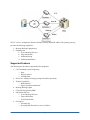
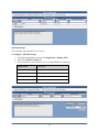
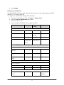
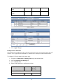
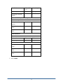
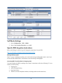
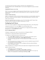
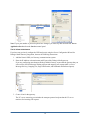
NetVanta Unified Communications Technical Note ___________________________________________________________________________________ Configuring the Dialogic Media Gateway Introduction The Dialogic 1000 and 2000 Media Gateway series allow integration with an existing PBX and the NetVanta UC server. The Media Gateway supports PBX systems from many different manufacturers including Alcatel, Avaya, Ericsson, Fujitsu, Hitachi, Intercom, Mitel, NEC, Nortel, Rohm, Siemens, and Toshiba, which allow you to bridge unified communications capability with your existing telephony system. This guide will assist you in configuring your media gateway and provide guidance on integrating your existing PBX system for IP telephony. The following Dialogic part numbers are available through the Dialogic distribution channel. Dialogic® 1000 Media Gateway Series Dialogic Part Number Description DMG1008LSW Analog Media gateway DMG1008DNIW Digital Station Emulation Gateway DMG1008MTLDNIW Digital Station Emulation Gateway for Mitel PBXs DMG1008RLMDNIW Digital Station Emulation Gateway for Rolm PBXs 1 Dialogic® 2000 Media Gateway Series Dialogic Part Number Description DMG2030DTI Single span T1/E1/Q.SIG Media gateway to support up to 30 channels DMG2060DTI Dual span T1/E1/Q.SIG Media gateway to support up to 60 channels DMG2120DTI Quad span T1/E1/Q.SIG Media gateway to support up to 120 channels Integration Topology The Dialogic Media Gateways use the SIP protocol to communicate with the UC server and proprietary techniques to integrate with traditional PBXs. The UC server can support multiple gateways simultaneously to increase the number of channels to integrate with the PBX. The type of integration and the methods of integration can be found on the Dialogic web site: http://www.dialogic.com/support/helpweb/mg/integration.htm If you require more than one gateway to support the number of simultaneous calls for your application, you must take into consideration the PBX hunting type. “Hunting type” refers to the ordering technique the PBX uses to present incoming calls to the UC server – linear, circular – and the specific sequence that the PBX uses to send calls to the UC server. Best practices: 1. Configure the incoming and outgoing ports to arrive in reverse order. As an example, incoming calls originate on the first gateway (non-prime) and if all the ports are busy, use the last gateway (prime). When originating calls, the UC server uses the last gateway and the PBX presents calls starting on the first gateway. This is done to reduce „glare‟ or the possibility of collisions with incoming and outgoing calls. 2. Configure as many ports on the primary gateway as possible. For example, if the application requires an uneven number of gateways (for example, the application requires 12 ports but you have enough ports to configure 16) make sure that the last gateway (prime) is provisioned with as many ports as possible. The primary gateway, the SIP media gateway configured in the UC server, is used for all outbound calls and activating/deactivating message waiting lights. If you have more than one gateway, you must configure the PBX to terminate on the other gateways first. It is a best practice, to arrange the incoming and outgoing calls to originate in opposite directions from each other. If you are using more than one gateway, make sure that the majority of your incoming calls do not originally get offered on the primary gateway. 2 The UC server is configured to have the Primary Gateway domain/IP address. The primary gateway provides the following capabilities: 1. Message Waiting Light gateway 2. Outgoing calls a. Active Message Delivery b. Pager notification c. Outbound faxing d. Outbound notification Supported Features The following are the features supported by the integration: Call forwarding to personal greeting o Busy o Ring-no-answer o Unconditional Direct call – Manage messages (prompt for mailbox password) Transfer Capabilities o Blind transfers1 o Supervised/Assisted transfers1 Message Waiting Lights2 Caller ID (If supplied by PBX) Notification Services o Active Message Delivery o Pager Notification o E-mail Notification Fax support o Incoming Fax o Incoming DID Fax (direct to user‟s mailbox) 3 o Outgoing Fax (desktop fax) o Fax-on-demand Outbound notification (database integration with outbound notification) 1. The media gateway attempts to use the same channel/port for performing transfers if it is a supported capability of the PBX. This minimizes the number of ports required for transfer applications like automated attendants. 2. Some PBX integrations require the same ports to turn on and off Message Waiting Light. The Dialogic Gateways remember which port turned on a message waiting light for an extension. However, this information is lost if the gateway is reset. 4 PBX Compatibility The Dialogic Media Gateways support a number of protocols, which allows for compatibility with a wide variety of PBX systems. These protocols include: Analog DTMF o A method of inter-switch signaling that uses dual-tone multi-frequency (DTMF) tones for signaling call reason and calling/called party information. Serial (RS-232) o Standard for serial binary data signals connecting between a DTE (Data terminal equipment) and a DCE (Data Circuit-terminating Equipment). o There are a number of serial protocols (SMDI, MCI, MD110 formats). Ensure that the Media Gateway supports the specific format for your PBX. CAS o CAS (Channel-associated signaling) is a signaling protocol that control signals, such as those for synchronizing and bounding frames, in the same channels as voice and data signals. QSIG o QSIG is a common channel signaling protocol based on ISDN Q.931 standards and is used by many digital PBXs. QSIG is used for the establishment and release of calls and for the control of a large number of features. The Dialogic Media Gateways are compatible with over 20 PBX systems from several manufacturers. Specific configuration of these PBX systems is provided by Dialogic. Refer to the Dialogic web site for compatibility and PBX configuration guides. http://www.dialogic.com/support/helpweb/mg/integration.htm Initial Configuration There are two methods of configuration: Serial Port or via HTTP. The detailed instructions can be found in the Dialogic Media Gateway Getting Started Guide. A summary is provided for convenience. Serial Interface: Using the serial port, you can run the basic configuration and set the parameters for both the gateway and PBX. Refer to section Error! Reference source not found. for the 1000 series or section Error! Reference source not found. for the 2000 series. Web configuration: The default IP address of the Dialogic Media Gateway is 10.12.13.74. To access the configuration screen, configure the local computer with an IP address on the same subnet (for example, 10.12.13.75) and, using a web browser, navigate to http://10.12.13.74. 5 DMG 1000 Series Configuration - Serial Interface 1. Connect the serial cable to the serial connector on the back of the unit labeled diagnostics, and connect the other end to the serial connector on your PC. 2. Using a terminal interface program such as HyperTerminal, create a connection using the following parameters: Baud rate: 38400 Parity: None Data Bits: 8 Stop Bits: 1 Hardware Flow Control: Off 3. Select connect. 4. Press the Enter key until the following prompt appears: PIMG> 5. At the prompt, type pwd and press Enter. 6. When prompted, type the password for the admin user (the default is IpodAdmin) and press Enter. 7. At the prompt, type quickcfg and press Enter. 8. You are prompted to enter the following parameters: Client IP Address: Type the IP Address that you want to assign to the media gateway. Client Subnet Mask: Type the subnet mask that you want to assign to the media gateway. Default Network Address: Type the IP Address of the default network router. Select Operating Mode: Type SIP. PBX Type: Type the value that corresponds to your PBX. 9. Type Restart at the PIMG> prompt. 6 DMG 2000 Series Configuration – Serial Interface 1. Connect the serial cable to the COM 2 connector on the gateway, and connect the other end to the serial connector on your PC. 2. Using a terminal interface program such as HyperTerminal, create a connection using the following parameters: Baud rate: 115200 Parity: None Data Bits: 8 Stop Bits: 1 Hardware Flow Control: Off 3. Select connect. 4. Press the Enter key until the following prompt appears: PIMG> 5. At the prompt, type pwd and press Enter. 6. When prompted, type the password for the admin user (the default is IpodAdmin) and press Enter. 7. At the prompt, type quickcfg and press Enter. 8. You are prompted to enter the following parameters: Client IP Address: Type the IP Address that you want to assign to the media gateway. Client Subnet Mask: Type the subnet mask that you want to assign to the media gateway. Default Network Address: Type the IP Address of the default network router. Select Operating Mode: Type SIP. Line Mode: Type T1 for a T1 digital link and E1 for an E1 digital link. Signaling Mode: You can type either CAS or ISDN depending on the type of digital link. If you select T1 CAS, you are prompted to select the Loop Start protocol. If you select ISDN, you are prompted to specify the T1 protocol to be used. 9. Type Restart at the PIMG> prompt. 7 Configuring the Media Gateway The last steps required in configuring the media gateway is to configure the dial plan, adjust the advanced settings, configure the serial protocol (if required), and set up integration with the UC server. Dialogic has PBX specific configuration files that can be imported into the Media Gateway to ensure that the custom PBX settings are configured correctly. The Dialogic Media Gateway software available from Dialogic contains the latest versions of configuration files for the PBXs that they support. The following configuration steps are required to integrate with the UC server: 1. 2. 3. 4. 5. 6. SIP Parameters CPID Manipulation Inbound VoIP Call Routing Inbound TDM Routing Call Connect Mode for answer supervision Specific PBX Integration instructions available from Dialogic The PBX integration configuration settings vary depending on the PBX manufacturer, PBX model and version and integration type. For specific instructions, see the specific Dialogic configuration guide for the PBX model and integration type. To manage the media gateway 1. Open your web browser and enter the IP Address of your media gateway. 2. When the login prompt appears, enter the following: Username: admin Password: IpodAdmin SIP The SIP parameters ensure that the Media Gateway uses the appropriate configuration parameters to integrate with the UC server SIP PBX (via Gateway) Communications System. Any parameters not listed below must be set as the default configuration or as recommended by the relative PBX Integration guide provided by Dialogic. Navigate to Configure > VoIP > General and ensure the following parameters are configured: User-Agent Host and Domain Name: IP Address or FQDN of the UC server Transport Type: UDP (Match the transport type of UC Port) Call as Domain Name: No SIP URI Scheme Enabled: No Invite Expiration (sec): 120 Server DNS Server Address: As appropriate for network Registration Server Address: <Blank> 8 TCP/UDP UDP/TCP Transport enabled: Yes TCP/UDP Server Port: 5060 TCP Inactivity Timer (sec): 30 TLS TLS Transport Enabled: No Proxy Primary Proxy Server Address: <Blank> Backup Proxy Server Address: <Blank> Monitoring Monitor Call Connections: No Routing Table The routing table describes a set of rules used to define the characteristics of a call routed through the gateway. The primary characteristics include the destination address and the CPID (call party identification) information. The dial plan affects calls originating from the VoIP side, and calls originating from the TDM (T1, E1, analog, and so on) side. TDM Trunk Group The TDM Trunk group will be used to route calls between the attached PBX and the UC server. Using regular expressions or wildcard characters you can define the range of ports that you will use. To configure the TDM trunk group, follow these steps: 1. Using the left-hand menu navigate to Configure > Routing Table. 2. Select the TDM Trunk Groups radio button. 3. Ensure that entries for both voice and message waiting ports are included. The following table shows some possible values. 4. Select Submit. Option Name Voice Message Waiting Name Any TdmMwis Selection Direction Ascending Descending Selection Mode Linear Linear Port/Channel Content * * Note: The Port/Channel content can also include a restricted range of ports. The default configuration is the * character (for all channels) 9 VoIP Host Groups The VoIP Host group identifies the UC server. To configure VoIP Host Groups 1. Using the left-hand menu navigate to Configuration > Routing Table. 2. Select the VoIP Host Groups tab. 3. Ensure that there is an entry for the UC server that includes the following. Option Name UC Server Name UC Server Load-Balanced Ascending Fault-Tolerant Linear Host List <IP Address of UC Server>:5080 10 4. Select Submit Routing Inbound TDM Calls The Inbound TDM Call Routing table is the main table used to route calls originating from the TDM interface (T1, E1, analog, and so on). To configure the inbound TDM routing, follow these steps: 1. 2. 3. 4. Using the left-hand menu navigate to Configure > Routing Table. Select the Inbound TDM Routing radio button. Modify or add a new rule. Ensure the Inbound TDM Rules are configured as follow: Option Name Voice Message Waiting Anonymous Enabled Yes Yes Yes Rule Label To/From PBX Message Waiting Anonymous Request Type Call Message Call Trunk Group Any (As defined from above) TdmMwis (as defined above) Any Inbound TDM Rules Inbound TDM Request Matching CPID Matching Calling name and number * * * Called Number and Name * * * Redirect Number and name * * * Outbound Destination VoIP VoIP VoIP Host Group UC Server UC Server UC Server S S “Unknown Number” Outbound Routes Device Selection CPID Manipulation Calling Number, Calling Name 11 Called Number, Called name D D D Redirect Number and Name R R R 5. Select Apply Changes. Routing Inbound VoIP Calls The Inbound VoIP Call Routing table is the main table used to route calls originating from the VoIP interface. This is applicable for outbound fax, outbound IVR, and Supervised (assisted) transfers. To configure VoIP call routing, follow these steps: 1. 2. 3. 4. Navigate to Configuration > Routing Table using the left-hand menu. Select the Inbound VoIP Routing tab. Select Add Rule Row. Ensure the dial plan rule is configured as follows: Option Name Voice Message Waiting Yes Yes Inbound VoIP Rules Enabled 12 Rule Label To/From UC Server InboundVoipMwi Request Type Call Message Originating VoIP Host Address * * Inbound VoIP Request Matching CPID Matching Calling name and number * * Called Number and Name * * Redirect Number and name * * Outbound Destination TDM TDM Host Group Any TdmMwis Calling Number, Calling Name S S Called Number, Called name D D Redirect Number and Name R R Outbound Routes Device Selection CPID Manipulation 5. Select Submit. 13 VoIP Media Settings 1. Select Configuration > VoIP > Media 2. Ensure Voice Activity Detection is set to Off. Specific PBX Integration Instructions Refer to the Dialogic website for specific integration instructions for your PBX. http://www.dialogic.com/support/helpweb/mg/integration.htm Message Waiting Lights The UC server is replacing an existing voice mail so the message waiting lights status is out of sync. Follow the PBX manufacturer‟s instructions to reset the message waiting lights. Accessing PBX Trunk Facilities for Outgoing Calls You must configure the PBX according to the vendor‟s instructions to allow the following UC server features to work correctly. Outgoing Fax Active Message Delivery Pager Notification Transfer to external telephone numbers (including trunk-to-trunk connections) 14 You must also ensure best practices to reduce or eliminate issues with fraudulent use of telecommunications services. The PBX and the UC server must be configured as a system to eliminate Toll Fraud. Outgoing PBX Feature Access Codes The UC server must be configured with the appropriate dialing plan feature access codes to dial external telephone numbers. Most PBXs require an external dialing access code (for example, 9) for accessing outgoing lines. Trunk-to-Trunk Connectivity If there is a requirement to be able to transfer incoming external calls to an external telephone number, the PBX must be configured to allow this capability. Consult the PBX Manufacturer‟s directions to allow trunk-to-trunk connections. Integrations using digital trunk based facilities, such as T1/E1 CAS, PRI or Q.SIG, Trunk to Trunk Connectivity MUST be enabled on the PBX for outgoing calls to succeed. Configuring the UC Server The UC server must be configured to integrate with the Dialogic Media Gateway. The media gateway communicates with the UC server on port 5080 for voice mail and related services. You can create the Dialogic Gateway either through the Server Configuration Wizard or manually through the the UC client Administrator interface. Server Configuration Wizard Configuring a communications system is a step in the Server Configuration Wizard. Consult the Server Configuration Wizard for detailed information. To configure the Communications System, follow these steps: 1. Select Generic PBX (via Gateway) from the list of supported communications systems. 2. Configure the name (the default name is Generic PBX (via Gateway)). 3. Specify the answering group number. This is the number that a user dials to retrieve voice messages. 4. Select the appropriate network adapter. Generally, you need to consider this step only if the UC server has more than one network adapter. 5. Choose whether or not you want the Server Configuration Wizard to modify the Windows Firewall. The default is enabled. After you finish the Server Configuration Wizard, ensure that the Port Configuration has the correct SIP options by doing the following: 1. Launch the the UC server client application. 2. In the Administration tab, select Ports > Generic PBX (via Gateway). 3. Ensure the gateway is configured to match the transport protocol and the UC server port. By default, it is recommended to use UDP transport and UDP port 5080. 15 Note: If your port number or protocol options have changed, you must stop and restart the UC Server Application Services from the Services control panel. The UC Client Administrator If you have not previously configured a PBX and port(s) using the Server Configuration Wizard for Dialogic Media Gateway integration, then use the following instructions. 1. Add the Generic PBX (via Gateway) communications system. 2. Enter the IP Address or domain name and IP port of the Dialogic Media gateway. If you are configuring more than one Dialogic Media Gateway, ensure that the gateway that you select will be used for Message Waiting requests and outgoing call requests (that is, Active Message Delivery, Outgoing Fax, Pager Notification, and Outbound notification requests). 3. Create a Port for that gateway. The UC server answering port includes the transport protocol and port that the UC server monitors for incoming call requests. 16 Transport Port and protocol: The transport protocol can be one of TCP, UDP or TCP and UDP. Port Number: By default, it is recommended to use IP port 5080. Ensure the gateway is configured to match the transport protocol and the UC server port. 4. Add the users in the UC client to the generic PBX communication system. Testing the Configuration To make sure that the Dialogic Media Gateway configuration is working, you must run the following tests. Pre-Testing Setup To ensure you can properly test the gateway 1. Create a couple of users on the PBX and the UC server. 2. Create an identity for those users. 3. Create an auto-attendant identity to test incoming calls. Testing Procedures 1. Internal Direct – Call to voicemail Place a call to the voice mail access number and set the voice mail password for that user. 2. Forwarded Call Place a call from one user to another, and then transfer the call to an external number. 17 3. Leave a voice mail Place a call from one user to another and wait for the call to be transferred to voice mail. Leave a message and check that the message waiting indicator is turned on. 4. Listen to voice mail Place a call to voice mail from the user you left a message for. Listen to the message and delete it when prompted. Check that the message waiting indicator is turned off. 5. Transfer from auto-attendant Call into the auto-attendant and transfer to an extension. Make sure the call is transferred and the destination is ringing. Check that you verify all the possible failure conditions: a. Transfer to valid extension b. Transfer to invalid number c. Transfer to busy number 18