1
Dialogic® 1000 and 2000
Media Gateway Series
User’s Guide
November 2009
64-0346-07
Copyright and Legal Notice
Copyright © 2007-2009 Dialogic Corporation. All Rights Reserved. You may not reproduce this document in whole or in part without permission in writing from
Dialogic Corporation at the address provided below.
All contents of this document are furnished for informational use only and are subject to change without notice and do not represent a commitment on the part of
Dialogic Corporation or its subsidiaries (“Dialogic”). Reasonable effort is made to ensure the accuracy of the information contained in the document. However,
Dialogic does not warrant the accuracy of this information and cannot accept responsibility for errors, inaccuracies or omissions that may be contained in this
document.
INFORMATION IN THIS DOCUMENT IS PROVIDED IN CONNECTION WITH DIALOGIC® PRODUCTS. NO LICENSE, EXPRESS OR IMPLIED, BY ESTOPPEL
OR OTHERWISE, TO ANY INTELLECTUAL PROPERTY RIGHTS IS GRANTED BY THIS DOCUMENT. EXCEPT AS PROVIDED IN A SIGNED AGREEMENT
BETWEEN YOU AND DIALOGIC, DIALOGIC ASSUMES NO LIABILITY WHATSOEVER, AND DIALOGIC DISCLAIMS ANY EXPRESS OR IMPLIED
WARRANTY, RELATING TO SALE AND/OR USE OF DIALOGIC PRODUCTS INCLUDING LIABILITY OR WARRANTIES RELATING TO FITNESS FOR A
PARTICULAR PURPOSE, MERCHANTABILITY, OR INFRINGEMENT OF ANY INTELLECTUAL PROPERTY RIGHT OF A THIRD PARTY.
Dialogic products are not intended for use in medical, life saving, life sustaining, critical control or safety systems, or in nuclear facility applications.
Due to differing national regulations and approval requirements, certain Dialogic products may be suitable for use only in specific countries, and thus may not
function properly in other countries. You are responsible for ensuring that your use of such products occurs only in the countries where such use is suitable. For
information on specific products, contact Dialogic Corporation at the address indicated below or on the web at www.dialogic.com.
It is possible that the use or implementation of any one of the concepts, applications, or ideas described in this document, in marketing collateral produced by or
on web pages maintained by Dialogic may infringe one or more patents or other intellectual property rights owned by third parties. Dialogic does not provide any
intellectual property licenses with the sale of Dialogic products other than a license to use such product in accordance with intellectual property owned or validly
licensed by Dialogic and no such licenses are provided except pursuant to a signed agreement with Dialogic. More detailed information about such intellectual
property is available from Dialogic’s legal department at 9800 Cavendish Blvd., 5th Floor, Montreal, Quebec, Canada H4M 2V9. Dialogic encourages all users
of its products to procure all necessary intellectual property licenses required to implement any concepts or applications and does not condone or
encourage any intellectual property infringement and disclaims any responsibility related thereto. These intellectual property licenses may differ from
country to country and it is the responsibility of those who develop the concepts or applications to be aware of and comply with different national
license requirements.
Dialogic, Dialogic Pro, Brooktrout, Diva, Cantata, SnowShore, Eicon, Eicon Networks, NMS Communications, NMS (stylized), Eiconcard, SIPcontrol, Diva ISDN,
TruFax, Exnet, EXS, SwitchKit, N20, Making Innovation Thrive, Connecting to Growth, Video is the New Voice, Fusion, Vision, PacketMedia, NaturalAccess,
NaturalCallControl, NaturalConference, NaturalFax and Shiva, among others as well as related logos, are either registered trademarks or trademarks of Dialogic
Corporation or its subsidiaries. Dialogic’s trademarks may be used publicly only with permission from Dialogic. Such permission may only be granted by Dialogic’s
legal department at 9800 Cavendish Blvd., 5th Floor, Montreal, Quebec, Canada H4M 2V9. Any authorized use of Dialogic’s trademarks will be subject to full
respect of the trademark guidelines published by Dialogic from time to time and any use of Dialogic’s trademarks requires proper acknowledgement.
Windows is a registered trademark of Microsoft Corporation in the United States and/or other countries. Other names of actual companies and product mentioned
herein are the trademarks of their respective owners.
Publication Date: November 2009
Document Number: 64-0346-07
Dialogic® 1000 and 2000 Media Gateway Series User’s Guide
Software License Agreement
This is a Software License Agreement ("Agreement") between you the
Company and your Affiliates and all your Authorized Users (collectively
referred to hereinafter as "You" or "Your") and Dialogic Corporation
("Dialogic").
Do not use any Dialogic Corporation software and any associated materials
(collectively, the "Software") which are loaded on the Dialogic® Media
Gateway hardware product ("Product") until You have carefully read the
following terms and conditions. By using the Software, You agree to the terms
of this Agreement. If You do not wish to so agree, Dialogic is unwilling to
license the Software to You. In such event, You may not use or copy the
Software, and You should promptly contact Dialogic for instructions on return
of the unused Product(s) in accordance with Dialogic's standard return
policies. Using the Product constitutes Your acceptance of the terms and
conditions contained in this Agreement. You assume responsibility for the
selection of the Software to achieve Your intended results, and for the
installation, use, and results obtained from the Software.
LICENSE. You may use the Software solely in connection with Your
organization's use of the Product, subject to these conditions:
You may not copy any part of the Software or its documentation, except as
authorized in (a) - (d) below, and You agree to prevent unauthorized copying
of the Software
(a) You may install and use one copy of the Software on a single-user
computer, file server, or on a workstation of a local area network, and only in
conjunction with a legally acquired Product;
(b) The primary Authorized User on the computer on which the Software is
installed may make a second copy for his/her exclusive use on either a home
or portable computer;
(c) You may copy the Software into any machine readable or printed form for
backup purposes in support of your use of one copy of the Software; and
(d) You may make one copy of Dialogic's documentation pertaining to the
Software, provided that all copyright notices contained within the
documentation are retained;
You may not modify the Software and/or merge it into another program.
You may transfer the Software, its documentation and its license to another
eligible party within Your Company if the other party agrees to accept the
terms and conditions of this Software License Agreement. If You transfer the
Software and documentation You must at the same time either transfer all
copies whether in printed or machine readable form to the same party or
destroy any copies not transferred; this includes all modifications and portions
of the Software contained in or merged into other Software.
You may not reverse engineer, decompile, disassemble, rent, lease or
sublicense the Software.
You may not use, copy, modify or transfer the Software and documentation, or
any copy in whole or in part, except as expressly provided for in this
Agreement.
If You transfer possession of any copy of the Software or documentation to
another party in any way other than as expressly permitted in this Agreement,
this license is automatically terminated.
The Software may include portions offered on terms in addition to those set
forth herein, as set out in a license accompanying those portions.
OWNERSHIP OF SOFTWARE AND COPYRIGHTS. Title to all copies
of the Software remains with Dialogic, its subsidiaries, or its suppliers. The
Software is copyrighted and protected by the laws of Canada, the United
States and other countries, and by international treaty provisions. You may not
remove any copyright notices from the Software, which you must treat like
any other copyrighted material except as expressly permitted in this
Agreement. Dialogic may make changes to the Software, and/or to items
referenced therein, at any time and without notice, but Dialogic is not
obligated to support or update the Software. Except as otherwise expressly
provided, Dialogic grants no express or implied right under Dialogic patents,
copyrights, trademarks, trade secrets or other intellectual property rights in
connection with the Software. You may transfer the Software only if the
recipient agrees to be fully bound by these terms and provided that You retain
no copies of the Software.
UPGRADES OF ADDED FEATURES: If the Software is provided as an
upgrade or added feature and the upgrade or added feature is an upgrade or
added feature from another software product licensed to You and Your
Authorized Users by Dialogic, the upgrade or added feature is governed by the
License Agreement earlier provided with that software product package and
the present Agreement does not grant you additional license(s).
THIRD PARTY SOFTWARE: Third party software (e.g. - drivers, utilities,
operating system components, etc.) which may be distributed with the
Software or Product hereunder is provided "AS IS" without warranty of any
kind, whether express or implied, including warranties of merchantability,
non-infringement or fitness for a particular purpose, and your use and
installation thereof is also subject to the terms and conditions of any third
party licenses which may be supplied with such software. Some Software
components may be subject to open source license provisions and Your use
and further distribution of such Software is subject to the respective open
source license under which it is provided. Please see below for additional third
party license information related to certain third party software. Dialogic
expressly disclaims liability of any kind with respect to your installation or
use of third party software.
TERM: This Agreement is effective until terminated. You may terminate it at
any time. It will also terminate upon conditions set forth elsewhere in this
Agreement or immediately if you fail to comply with any terms or conditions
of this Agreement. You agree upon such termination to destroy the Software
and documentation together with all copies thereof.
LIMITATION OF LIABILITY. TO THE MAXIMUM EXTENT
PERMITTED BY APPLICABLE LAW, IN NO EVENT WILL DIALOGIC
CORPORATION, ITS SUBSIDIARIES, ITS SUPPLIERS OR ITS
RESELLERS OR THEIR RESPECTIVE DIRECTORS, OFFICERS OR
EMPLOYEES
BE LIABLE FOR ANY INDIRECT, SPECIAL,
INCIDENTAL OR CONSEQUENTIAL DAMAGES ARISING OUT OF
YOUR USE OF OR INABILITY TO USE THE SOFTWARE, INCLUDING,
WITHOUT LIMITATION, DAMAGES FOR LOSS OF GOODWILL, LOST
PROFITS, BUSINESS INTERRUPTION, LOSS OF INFORMATION,
WORK STOPPAGE, COMPUTER FAILURE OR MALFUNCTION, OR
ANY AND ALL OTHER DIRECT, INDIRECT, CONSEQUENTIAL OR
INCIDENTAL DAMAGES ARISING OUT OF THE USE OR INABILITY
TO USE THE SOFTWARE, EVEN IF DIALOGIC CORPORATION OR A
SUBSIDIARY HAS BEEN ADVISED OF THE POSSIBILITY OF SUCH
DAMAGES, OR FOR ANY CLAIM BY ANY OTHER PARTY,
REGARDLESS OF THE LEGAL OR EQUITABLE THEORY
(CONTRACT, TORT OR OTHERWISE) UPON WHICH THE CLAIM IS
BASED. IN ANY CASE, DIALOGIC CORPORATION OR ITS
SUBSIDIARIES' ENTIRE LIABILITY UNDER ANY PROVISION OF
THIS SOFTWARE LICENSE AGREEMENT SHALL NOT EXCEED IN
THE AGGREGATE THE SUM OF THE FEES THAT YOU PAID FOR THIS
SOFTWARE LICENSE (IF ANY). SOME JURISDICTIONS DO NOT
ALLOW THE EXCLUSION OR LIMITATION OF INCIDENTAL OR
CONSEQUENTIAL DAMAGES, SO THIS EXCLUSION AND
LIMITATION MAY NOT BE APPLICABLE.
US GOVERNMENT RESTRICTED RIGHTS. The Software is provided
with "RESTRICTED RIGHTS." Use, duplication, or disclosure by the US
Government is subject to restrictions as set forth in FAR52.227-14 and
DFAR252.227-7013 et seq. or its successor. Use of the Software by the
Government constitutes acknowledgement of Dialogic's proprietary rights
therein.
EXPORT CONTROL. You agree to comply with all export laws and
restrictions and regulations of the Canada, the United States and other
applicable governments as well as their agencies or authorities, and not to
export or re-export the Software or any direct product thereof in violation of
any such restrictions, laws or regulations, or without all necessary approvals.
By downloading or using the Software, You agree to the foregoing and
represent and warrant that You comply with these conditions.
High Risk Activities. The Software is not fault-tolerant and is not designed,
manufactured or intended for use or resale as on-line control equipment in
hazardous environments requiring fail-safe performance, such as in the
operation of nuclear facilities, aircraft navigation or communication systems,
air traffic control, direct life support machines, or weapons systems, in which
the failure of the Software could lead directly to death, personal injury, or
severe physical or environmental damage ("High Risk Activities").
Accordingly, Dialogic, its subsidiaries and its suppliers specifically disclaim
any express or implied warranty of fitness for High Risk Activities. You agree
that Dialogic, its subsidiaries and its suppliers will not be liable for any claims
or damages arising from the use of the Software in such applications.
LIMITED WARRANTY: The only warranty Dialogic makes is that the
medium on which the Software is recorded will be replaced without charge if
Dialogic, in good faith, determines that it was defective in materials or
workmanship and if returned to your supplier with a copy of your receipt
within ninety (90) days from the date you received it. Dialogic offers no
warranty for your reproduction of the Software. This Limited Warranty is void
if failure of the Software has resulted from accident, misuse, abuse or
misapplication. This limited warranty gives You specific legal rights. You may
have others, which may vary from jurisdiction to jurisdiction.
EXCLUSION OF OTHER WARRANTIES. Except as defined above in
"LIMITED WARRANTY," THE SOFTWARE IS PROVIDED "AS IS"
WITHOUT ANY EXPRESS OR IMPLIED WARRANTY OF ANY KIND
INCLUDING
WARRANTIES
OF
MERCHANTABILITY,
NONINFRINGEMENT, FITNESS FOR A PARTICULAR PURPOSE, OR
AGAINST LATENT DEFECTS. Dialogic does not warrant or assume
responsibility for the accuracy or completeness of any information, text,
graphics, links or other items contained within the Software.
Right to Audit: If this Software is licensed for use in a Company, Your
Company agrees to keep all usual and proper records and books of accounts
and all usual proper entries relating to each reproduction and Authorized User
of the Software during the term of this Agreement and for a period of three (3)
years thereafter. During this period, Dialogic may cause an audit to be made of
the applicable records in order to verify Your compliance with this Agreement
and prompt adjustment shall be made to compensate for any errors or
omissions disclosed by such audit. Any such audit shall be conducted by an
independent certified public accountant selected by Dialogic and shall be
conducted during the regular business hours at Your offices and in such a
manner as not to interfere with Your normal business activities. Any such
audit shall be paid for by Dialogic unless material discrepancies are disclosed.
For such purposes, "material discrepancies" shall mean an overuse of the
Software by the number of Authorized Users within the Company exceeding
the paid licensed number by more than three percent (3%). If material
discrepancies are disclosed, Your Company agrees to pay Dialogic for the
costs associated with the audit as well as the license fees for the additional
Authorized Users. In no event shall audits be made more frequently than semiannually unless the immediately preceding audit disclosed a material
discrepancy.
TERMINATION OF THIS AGREEMENT. Dialogic may terminate this
Software License Agreement at any time if You violate its terms. Upon
termination, You will immediately destroy the Software or return all copies of
the Software to Dialogic at Your cost.
APPLICABLE LAWS. Claims arising under this Software License
Agreement shall be governed by the laws of the Province of Quebec,
excluding its principles of conflict of laws and the United Nations Convention
on Contracts for the Sale of Goods.
ADDITIONAL TERMS. Dialogic is not obligated under any other
agreements unless they are in writing and signed by an authorized
representative of Dialogic. All notices to Dialogic under this Agreement shall
be sent to Dialogic's legal department at 9800 Cavendish Blvd., 5th Floor,
Montreal, Quebec, Canada H4M2V9. In the event that any provision of this
Agreement is found to be invalid, the remainder of the Agreement shall
remain in full force and effect and the closest legally valid alternative
provision giving effect to the intention of the original severed invalid clause
shall be deemed to be included in this Agreement.
APPLICABLE THIRD PARTY LICENSE INFORMATION:
(a) AMD Flash API (Memory Drivers 1.1).
The AMD Flash API (Memory Drivers 1.1) is distributed subject to the
terms on AMD's website which are as follows:
This software constitutes a basic shell of source code for programming all
AMD flash components. AMD will not be responsible for misuse or
illegal use of this software for devices not supported herein. AMD is
providing this source code "AS IS" and will not be responsible for issues
arising from incorrect user implementation of the source code herein. It is
the user's responsibility to properly design-in this source code. Include
this copyright notice if there is a location the end user would be able to
access: © Copyright 2002 Advanced Micro Devices, Inc.
(b) SSL Implementation
Copyright (C) 1995-1998 Eric Young ([email protected]) * All rights
reserved. This package is an SSL implementation written by Eric Young
The implementation was written so as to conform with Netscape's SSL.
This library is free for commercial and non-commercial use as long as the
following conditions are adhered to. The following conditions apply to all
code found in this distribution, be it the RC4, RSA, lhash, DES, etc.,
code; not just the SSL code. The SSL documentation included with this
distribution is covered by the same copyright terms except that the holder
is Tim Hudson ([email protected]). Copyright remains Eric Young's, and
as such any Copyright notices in the code are not to be removed. If this
package is used in a product, Eric Young should be given attribution as
the author of the parts of the library used. This can be in the form of a
textual message at program startup or in documentation (online or
textual) provided with the package. Redistribution and use in source and
binary forms, with or without modification, are permitted provided that
the following conditions are met: 1. Redistributions of source code must
retain the copyright notice, this list of conditions and the following
disclaimer. 2. Redistributions in binary form must reproduce the above
copyright notice, this list of conditions and the following disclaimer in the
documentation and/or other materials provided with the distribution. 3.
All advertising materials mentioning features or use of this software must
display the following acknowledgement: "This product includes
cryptographic software written by Eric Young ([email protected])" The
word 'cryptographic' can be left out if the rouines from the library being
used are not cryptographic related:-). 4. If you include any Windows
specific code (or a derivative thereof) from the apps directory (application
code) you must include an acknowledgement: "This product includes
software written by Tim Hudson ([email protected])" THIS
SOFTWARE IS PROVIDED BY ERIC YOUNG ``AS IS'' AND ANY
EXPRESS OR IMPLIED WARRANTIES, INCLUDING, BUT NOT
LIMITED
TO,
THE
IMPLIED
WARRANTIES
OF
MERCHANTABILITY AND FITNESS FOR A PARTICULAR
PURPOSE ARE DISCLAIMED. IN NO EVENT SHALL THE
AUTHOR OR CONTRIBUTORS BE LIABLE FOR ANY DIRECT,
INDIRECT,
INCIDENTAL,
SPECIAL,
EXEMPLARY,
OR
CONSEQUENTIAL DAMAGES (INCLUDING, BUT NOT LIMITED
TO, PROCUREMENT OF SUBSTITUTE GOODS OR SERVICES;
LOSS OF USE, DATA, OR PROFITS; OR BUSINESS
INTERRUPTION) HOWEVER CAUSED AND ON ANY THEORY OF
LIABILITY, WHETHER IN CONTRACT, STRICT LIABILITY, OR
TORT (INCLUDING NEGLIGENCE OR OTHERWISE) ARISING IN
ANY WAY OUT OF THE USE OF THIS SOFTWARE, EVEN IF
ADVISED OF THE POSSIBILITY OF SUCH DAMAGE. The license
and distribution terms for any publicly available version or derivative of
this code cannot be changed. i.e. this code cannot simply be copied and
put under another distribution license [including the GNU Public
License.]
Contractor/ manufacturer is:
DIALOGIC CORPORATION.
9800 Cavendish Blvd., Montreal, Quebec, Canada H4M 2V9
Contents
Revision History . . . . . . . . . . . . . . . . . . . . . . . . . . . . . . . . . . . . . . . . . . . . . . . . . . . . . . . . . . . . . 13
About This Publication . . . . . . . . . . . . . . . . . . . . . . . . . . . . . . . . . . . . . . . . . . . . . . . . . . . . . . . 17
Purpose . . . . . . . . . . . . . . . . . . . . . . . . . . . . . . . . . . . . . . . . . . . . . . . . . . . . . . . . . . . . . . .
Intended Audience . . . . . . . . . . . . . . . . . . . . . . . . . . . . . . . . . . . . . . . . . . . . . . . . . . . . . . .
How to Use This Publication . . . . . . . . . . . . . . . . . . . . . . . . . . . . . . . . . . . . . . . . . . . . . . .
Related Information . . . . . . . . . . . . . . . . . . . . . . . . . . . . . . . . . . . . . . . . . . . . . . . . . . . . . .
1
Overview . . . . . . . . . . . . . . . . . . . . . . . . . . . . . . . . . . . . . . . . . . . . . . . . . . . . . . . . . . . . . . . . . . . 21
1.1
1.2
1.3
1.4
1.5
1.6
2
Product Description . . . . . . . . . . . . . . . . . . . . . . . . . . . . . . . . . . . . . . . . . . . . . . . . . . . . . .
1.1.1 Phone Emulating . . . . . . . . . . . . . . . . . . . . . . . . . . . . . . . . . . . . . . . . . . . . . . . . .
Call Routing in Phone Emulating Mode . . . . . . . . . . . . . . . . . . . . . . . . . . . . . . . . . . . . . . .
1.2.1 Un-Routable Calls. . . . . . . . . . . . . . . . . . . . . . . . . . . . . . . . . . . . . . . . . . . . . . . . .
Voice over IP Address Translation . . . . . . . . . . . . . . . . . . . . . . . . . . . . . . . . . . . . . . . . . .
Security . . . . . . . . . . . . . . . . . . . . . . . . . . . . . . . . . . . . . . . . . . . . . . . . . . . . . . . . . . . . . . .
1.4.1 Access Security . . . . . . . . . . . . . . . . . . . . . . . . . . . . . . . . . . . . . . . . . . . . . . . . . .
1.4.2 Data Security . . . . . . . . . . . . . . . . . . . . . . . . . . . . . . . . . . . . . . . . . . . . . . . . . . . .
Web Interface . . . . . . . . . . . . . . . . . . . . . . . . . . . . . . . . . . . . . . . . . . . . . . . . . . . . . . . . . .
Online Help . . . . . . . . . . . . . . . . . . . . . . . . . . . . . . . . . . . . . . . . . . . . . . . . . . . . . . . . . . . .
21
22
26
26
27
28
28
28
28
31
Media Gateway Configuration . . . . . . . . . . . . . . . . . . . . . . . . . . . . . . . . . . . . . . . . . . . . . . . . . . 33
2.1
2.2
2.3
2.4
2.5
2.6
2.7
3
17
17
17
19
Setting the IP Address . . . . . . . . . . . . . . . . . . . . . . . . . . . . . . . . . . . . . . . . . . . . . . . . . . . .
Basic Configuration Via the Serial Port . . . . . . . . . . . . . . . . . . . . . . . . . . . . . . . . . . . . . . .
Changing the Password. . . . . . . . . . . . . . . . . . . . . . . . . . . . . . . . . . . . . . . . . . . . . . . . . . .
Configuration Procedure . . . . . . . . . . . . . . . . . . . . . . . . . . . . . . . . . . . . . . . . . . . . . . . . . .
Restart Options . . . . . . . . . . . . . . . . . . . . . . . . . . . . . . . . . . . . . . . . . . . . . . . . . . . . . . . . .
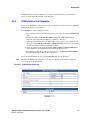
Importing and Exporting Configuration Information . . . . . . . . . . . . . . . . . . . . . . . . . . . . . .
2.6.1 Exporting Configuration Information . . . . . . . . . . . . . . . . . . . . . . . . . . . . . . . . . . .
2.6.2 Importing Configuration Information . . . . . . . . . . . . . . . . . . . . . . . . . . . . . . . . . . .
Upgrading the Software . . . . . . . . . . . . . . . . . . . . . . . . . . . . . . . . . . . . . . . . . . . . . . . . . . .
33
34
35
35
36
36
37
38
38
Parameter Reference . . . . . . . . . . . . . . . . . . . . . . . . . . . . . . . . . . . . . . . . . . . . . . . . . . . . . . . . . 41
3.1
3.2
3.3
IP Settings . . . . . . . . . . . . . . . . . . . . . . . . . . . . . . . . . . . . . . . . . . . . . . . . . . . . . . . . . . . . .
3.1.1 IP Settings, LAN1 . . . . . . . . . . . . . . . . . . . . . . . . . . . . . . . . . . . . . . . . . . . . . . . . .
3.1.2 IP Settings, LAN2 (DMG2000) . . . . . . . . . . . . . . . . . . . . . . . . . . . . . . . . . . . . . . .
3.1.3 IP Advanced Parameters (DMG2000) . . . . . . . . . . . . . . . . . . . . . . . . . . . . . . . . .
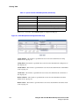
Management Protocols Parameters . . . . . . . . . . . . . . . . . . . . . . . . . . . . . . . . . . . . . . . . .
3.2.1 E-Mail Group. . . . . . . . . . . . . . . . . . . . . . . . . . . . . . . . . . . . . . . . . . . . . . . . . . . . .
3.2.2 SysLog Group . . . . . . . . . . . . . . . . . . . . . . . . . . . . . . . . . . . . . . . . . . . . . . . . . . . .
3.2.3 SNMP Group . . . . . . . . . . . . . . . . . . . . . . . . . . . . . . . . . . . . . . . . . . . . . . . . . . . .
3.2.4 Web Server Group . . . . . . . . . . . . . . . . . . . . . . . . . . . . . . . . . . . . . . . . . . . . . . . .
3.2.5 Telnet Server Group . . . . . . . . . . . . . . . . . . . . . . . . . . . . . . . . . . . . . . . . . . . . . . .
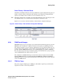
VoIP General Parameters . . . . . . . . . . . . . . . . . . . . . . . . . . . . . . . . . . . . . . . . . . . . . . . . .
3.3.1 User-Agent Group. . . . . . . . . . . . . . . . . . . . . . . . . . . . . . . . . . . . . . . . . . . . . . . . .
3.3.2 Server Group . . . . . . . . . . . . . . . . . . . . . . . . . . . . . . . . . . . . . . . . . . . . . . . . . . . .
Dialogic® 1000 and 2000 Media Gateway Series User’s Guide
Dialogic Corporation
41
42
43
44
47
47
49
50
52
53
53
54
56
5
Contents
3.4
3.5
3.6
3.7
3.8
3.9
3.10
3.11
3.12
3.13
3.14
3.15
3.16
3.17
3.18
6
3.3.3 TCP/UDP Group . . . . . . . . . . . . . . . . . . . . . . . . . . . . . . . . . . . . . . . . . . . . . . . . . . 58
3.3.4 TLS Group . . . . . . . . . . . . . . . . . . . . . . . . . . . . . . . . . . . . . . . . . . . . . . . . . . . . . . . 59
3.3.5 Proxy Group. . . . . . . . . . . . . . . . . . . . . . . . . . . . . . . . . . . . . . . . . . . . . . . . . . . . . . 61
3.3.6 Timing Group . . . . . . . . . . . . . . . . . . . . . . . . . . . . . . . . . . . . . . . . . . . . . . . . . . . . . 63
3.3.7 Monitoring Group . . . . . . . . . . . . . . . . . . . . . . . . . . . . . . . . . . . . . . . . . . . . . . . . . . 64
VoIP Media Parameters . . . . . . . . . . . . . . . . . . . . . . . . . . . . . . . . . . . . . . . . . . . . . . . . . . . 66
3.4.1 Audio Group. . . . . . . . . . . . . . . . . . . . . . . . . . . . . . . . . . . . . . . . . . . . . . . . . . . . . . 66
3.4.2 Fax Group . . . . . . . . . . . . . . . . . . . . . . . . . . . . . . . . . . . . . . . . . . . . . . . . . . . . . . . 70
3.4.3 SRTP Group . . . . . . . . . . . . . . . . . . . . . . . . . . . . . . . . . . . . . . . . . . . . . . . . . . . . . 70
VoIP Quality of Service Parameters . . . . . . . . . . . . . . . . . . . . . . . . . . . . . . . . . . . . . . . . . . 73
TDM General Parameters. . . . . . . . . . . . . . . . . . . . . . . . . . . . . . . . . . . . . . . . . . . . . . . . . . 75
TDM T1/E1 Parameters . . . . . . . . . . . . . . . . . . . . . . . . . . . . . . . . . . . . . . . . . . . . . . . . . . . 79
3.7.1 T1/E1 Mode Group . . . . . . . . . . . . . . . . . . . . . . . . . . . . . . . . . . . . . . . . . . . . . . . . 79
3.7.2 T1 CAS Protocol Group (T1 CAS Signaling Mode) . . . . . . . . . . . . . . . . . . . . . . . . 80
3.7.3 T1 ISDN Protocol Group (ISDN Signaling Mode) . . . . . . . . . . . . . . . . . . . . . . . . . 86
3.7.4 E1 ISDN Protocol Group (ISDN Signaling Mode) . . . . . . . . . . . . . . . . . . . . . . . . . 90
TDM Analog Parameters . . . . . . . . . . . . . . . . . . . . . . . . . . . . . . . . . . . . . . . . . . . . . . . . . . 94
3.8.1 Timing Group . . . . . . . . . . . . . . . . . . . . . . . . . . . . . . . . . . . . . . . . . . . . . . . . . . . . . 94
3.8.2 Feature Code Group . . . . . . . . . . . . . . . . . . . . . . . . . . . . . . . . . . . . . . . . . . . . . . . 95
3.8.3 Message Waiting Control Group . . . . . . . . . . . . . . . . . . . . . . . . . . . . . . . . . . . . . . 97
3.8.4 CPID Settings Group . . . . . . . . . . . . . . . . . . . . . . . . . . . . . . . . . . . . . . . . . . . . . . . 98
TDM Digital Parameters . . . . . . . . . . . . . . . . . . . . . . . . . . . . . . . . . . . . . . . . . . . . . . . . . . 101
TDM Port Enable Parameters. . . . . . . . . . . . . . . . . . . . . . . . . . . . . . . . . . . . . . . . . . . . . . 102
TDM Call Type Group. . . . . . . . . . . . . . . . . . . . . . . . . . . . . . . . . . . . . . . . . . . . . . . . . . . . 103
3.11.1 ISDN Call Type Rules . . . . . . . . . . . . . . . . . . . . . . . . . . . . . . . . . . . . . . . . . . . . . 103
TDM CPID Parsing Configuration. . . . . . . . . . . . . . . . . . . . . . . . . . . . . . . . . . . . . . . . . . . 107
Serial Ports Parameters . . . . . . . . . . . . . . . . . . . . . . . . . . . . . . . . . . . . . . . . . . . . . . . . . . 107
Serial Ports Switch Protocol Parameters . . . . . . . . . . . . . . . . . . . . . . . . . . . . . . . . . . . . . 110
3.14.1 Serial Mode (Master/Slave) . . . . . . . . . . . . . . . . . . . . . . . . . . . . . . . . . . . . . . . . . 111
3.14.2 Serial Interface Protocol . . . . . . . . . . . . . . . . . . . . . . . . . . . . . . . . . . . . . . . . . . . 111
3.14.3 MCI Message Extension Length . . . . . . . . . . . . . . . . . . . . . . . . . . . . . . . . . . . . . 111
3.14.4 MCI Message Type . . . . . . . . . . . . . . . . . . . . . . . . . . . . . . . . . . . . . . . . . . . . . . . 112
3.14.5 CPID Length . . . . . . . . . . . . . . . . . . . . . . . . . . . . . . . . . . . . . . . . . . . . . . . . . . . . 112
3.14.6 CPID Padding String . . . . . . . . . . . . . . . . . . . . . . . . . . . . . . . . . . . . . . . . . . . . . . 112
3.14.7 Voice Mail Port Length. . . . . . . . . . . . . . . . . . . . . . . . . . . . . . . . . . . . . . . . . . . . . 113
3.14.8 System Number . . . . . . . . . . . . . . . . . . . . . . . . . . . . . . . . . . . . . . . . . . . . . . . . . . 113
3.14.9 MWI Response Timeout . . . . . . . . . . . . . . . . . . . . . . . . . . . . . . . . . . . . . . . . . . . 113
3.14.10 IP Address of Serial Server . . . . . . . . . . . . . . . . . . . . . . . . . . . . . . . . . . . . . . . . . 113
3.14.11 Serial CPID Expiration . . . . . . . . . . . . . . . . . . . . . . . . . . . . . . . . . . . . . . . . . . . . . 114
Tone Detection Parameters . . . . . . . . . . . . . . . . . . . . . . . . . . . . . . . . . . . . . . . . . . . . . . . 114
3.15.1 Tone Generation Configuration Parameters . . . . . . . . . . . . . . . . . . . . . . . . . . . . 118
3.15.2 Editing the INI File Directly . . . . . . . . . . . . . . . . . . . . . . . . . . . . . . . . . . . . . . . . . 120
Certificates Parameters . . . . . . . . . . . . . . . . . . . . . . . . . . . . . . . . . . . . . . . . . . . . . . . . . . 121
3.16.1 Certificate Usage Group . . . . . . . . . . . . . . . . . . . . . . . . . . . . . . . . . . . . . . . . . . . 121
DSP Settings Parameters. . . . . . . . . . . . . . . . . . . . . . . . . . . . . . . . . . . . . . . . . . . . . . . . . 122
3.17.1 DSP Advanced Settings . . . . . . . . . . . . . . . . . . . . . . . . . . . . . . . . . . . . . . . . . . . 122
3.17.2 T.38 Fax Advanced Settings . . . . . . . . . . . . . . . . . . . . . . . . . . . . . . . . . . . . . . . . 130
3.17.3 Positive Answer Machine Detection . . . . . . . . . . . . . . . . . . . . . . . . . . . . . . . . . . 134
Non-Menu (Hidden) Parameters. . . . . . . . . . . . . . . . . . . . . . . . . . . . . . . . . . . . . . . . . . . . 135
3.18.1 Incompatible Message STATUS . . . . . . . . . . . . . . . . . . . . . . . . . . . . . . . . . . . . . 136
Dialogic® 1000 and 2000 Media Gateway Series User’s Guide
Dialogic Corporation
Contents
3.18.2 Inform On No PBX CPID (Phone Emulating Only) . . . . . . . . . . . . . . . . . . . . . . .
3.18.3 Inform On No PBX CPID Time (Phone Emulating Only) . . . . . . . . . . . . . . . . . .
3.18.4 ISDN Overlap Receive Minimum Digits . . . . . . . . . . . . . . . . . . . . . . . . . . . . . . .
3.18.5 ISDN Overlap Receive Timeout . . . . . . . . . . . . . . . . . . . . . . . . . . . . . . . . . . . . .
3.18.6 ISDN Service Class . . . . . . . . . . . . . . . . . . . . . . . . . . . . . . . . . . . . . . . . . . . . . .
3.18.7 SIP Phone Context From . . . . . . . . . . . . . . . . . . . . . . . . . . . . . . . . . . . . . . . . . .
3.18.8 SIP Phone Context To . . . . . . . . . . . . . . . . . . . . . . . . . . . . . . . . . . . . . . . . . . . .
3.18.9 SIP User Phone Enabled . . . . . . . . . . . . . . . . . . . . . . . . . . . . . . . . . . . . . . . . . .
3.18.10 Start Port for RTP . . . . . . . . . . . . . . . . . . . . . . . . . . . . . . . . . . . . . . . . . . . . . . . .
3.18.11 Unauthenticated SRTP Enable . . . . . . . . . . . . . . . . . . . . . . . . . . . . . . . . . . . . . .
3.18.12 UnEncrypted SRTCP Enable . . . . . . . . . . . . . . . . . . . . . . . . . . . . . . . . . . . . . . .
3.18.13 UnEncrypted SRTP Enable . . . . . . . . . . . . . . . . . . . . . . . . . . . . . . . . . . . . . . . .
4
Call Progress Tones . . . . . . . . . . . . . . . . . . . . . . . . . . . . . . . . . . . . . . . . . . . . . . . . . . . . . . . . . 141
4.1
4.2
5
5.2
5.3
5.4
141
142
142
144
144
145
147
148
148
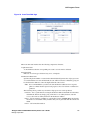
Routing Table Overview . . . . . . . . . . . . . . . . . . . . . . . . . . . . . . . . . . . . . . . . . . . . . . . . .
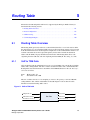
5.1.1 VoIP to TDM Calls . . . . . . . . . . . . . . . . . . . . . . . . . . . . . . . . . . . . . . . . . . . . . . .
5.1.2 TDM to VoIP Calls . . . . . . . . . . . . . . . . . . . . . . . . . . . . . . . . . . . . . . . . . . . . . . .
Router Configuration . . . . . . . . . . . . . . . . . . . . . . . . . . . . . . . . . . . . . . . . . . . . . . . . . . . .
5.2.1 Determining the Call Destination . . . . . . . . . . . . . . . . . . . . . . . . . . . . . . . . . . . .
5.2.2 Inbound TDM Call Routing Rules . . . . . . . . . . . . . . . . . . . . . . . . . . . . . . . . . . . .
5.2.3 Inbound VoIP Call Routing Rules . . . . . . . . . . . . . . . . . . . . . . . . . . . . . . . . . . . .
5.2.4 TDM Trunk Groups . . . . . . . . . . . . . . . . . . . . . . . . . . . . . . . . . . . . . . . . . . . . . . .
5.2.5 VoIP Host Groups . . . . . . . . . . . . . . . . . . . . . . . . . . . . . . . . . . . . . . . . . . . . . . . .
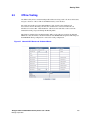
Offline Testing . . . . . . . . . . . . . . . . . . . . . . . . . . . . . . . . . . . . . . . . . . . . . . . . . . . . . . . . .
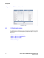
Call Routing Examples . . . . . . . . . . . . . . . . . . . . . . . . . . . . . . . . . . . . . . . . . . . . . . . . . .
151
151
152
152
153
154
159
165
167
169
170
Media Gateway Parsers . . . . . . . . . . . . . . . . . . . . . . . . . . . . . . . . . . . . . . . . . . . . . . . . . . . . . . 197
6.1
6.2
7
Viewing and Editing Call Progress Tones . . . . . . . . . . . . . . . . . . . . . . . . . . . . . . . . . . . .
Learning and Validating Call Progress Tones . . . . . . . . . . . . . . . . . . . . . . . . . . . . . . . . .
4.2.1 Learn Tone Web Page . . . . . . . . . . . . . . . . . . . . . . . . . . . . . . . . . . . . . . . . . . . .
4.2.2 Learning the Characteristics of Unknown Call Progress Tones . . . . . . . . . . . . .
4.2.3 Learn Tone Progress . . . . . . . . . . . . . . . . . . . . . . . . . . . . . . . . . . . . . . . . . . . . .
4.2.4 Learn Tone Results . . . . . . . . . . . . . . . . . . . . . . . . . . . . . . . . . . . . . . . . . . . . . .
4.2.5 Validating Call Progress Tones . . . . . . . . . . . . . . . . . . . . . . . . . . . . . . . . . . . . .
4.2.6 Validate Tone Progress . . . . . . . . . . . . . . . . . . . . . . . . . . . . . . . . . . . . . . . . . . .
4.2.7 Validate Tone Results. . . . . . . . . . . . . . . . . . . . . . . . . . . . . . . . . . . . . . . . . . . . .
Routing Table . . . . . . . . . . . . . . . . . . . . . . . . . . . . . . . . . . . . . . . . . . . . . . . . . . . . . . . . . . . . . . 151
5.1
6
136
137
137
137
137
138
138
139
139
139
140
140
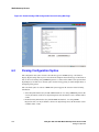
Configuration Options . . . . . . . . . . . . . . . . . . . . . . . . . . . . . . . . . . . . . . . . . . . . . . . . . . .
Parsing Configuration Syntax . . . . . . . . . . . . . . . . . . . . . . . . . . . . . . . . . . . . . . . . . . . . .
6.2.1 Display Translation Descriptors . . . . . . . . . . . . . . . . . . . . . . . . . . . . . . . . . . . . .
6.2.2 Call Class Rules . . . . . . . . . . . . . . . . . . . . . . . . . . . . . . . . . . . . . . . . . . . . . . . . .
197
198
201
202
Data Security. . . . . . . . . . . . . . . . . . . . . . . . . . . . . . . . . . . . . . . . . . . . . . . . . . . . . . . . . . . . . . . 205
7.1
7.2
7.3
Data Security Overview . . . . . . . . . . . . . . . . . . . . . . . . . . . . . . . . . . . . . . . . . . . . . . . . . .
Secure HTTP . . . . . . . . . . . . . . . . . . . . . . . . . . . . . . . . . . . . . . . . . . . . . . . . . . . . . . . . . .
7.2.1 HTTPS Certificate Configuration. . . . . . . . . . . . . . . . . . . . . . . . . . . . . . . . . . . . .
7.2.2 HTTPS Example . . . . . . . . . . . . . . . . . . . . . . . . . . . . . . . . . . . . . . . . . . . . . . . . .
SIP Call Control Security using TLS . . . . . . . . . . . . . . . . . . . . . . . . . . . . . . . . . . . . . . . .
7.3.1 TLS Certificate Configuration . . . . . . . . . . . . . . . . . . . . . . . . . . . . . . . . . . . . . . .
7.3.2 TLS Feature Configuration . . . . . . . . . . . . . . . . . . . . . . . . . . . . . . . . . . . . . . . . .
Dialogic® 1000 and 2000 Media Gateway Series User’s Guide
Dialogic Corporation
205
205
206
207
207
208
208
7
Contents
7.4
7.5
8
Unit Status . . . . . . . . . . . . . . . . . . . . . . . . . . . . . . . . . . . . . . . . . . . . . . . . . . . . . . . . . . . . . . . . . 215
8.1
8.2
8.3
8.4
8.5
8.6
8.7
9
7.3.3 TLS Examples . . . . . . . . . . . . . . . . . . . . . . . . . . . . . . . . . . . . . . . . . . . . . . . . . . . 209
Secure Voice Data . . . . . . . . . . . . . . . . . . . . . . . . . . . . . . . . . . . . . . . . . . . . . . . . . . . . . . 210
7.4.1 Configuration . . . . . . . . . . . . . . . . . . . . . . . . . . . . . . . . . . . . . . . . . . . . . . . . . . . . 210
7.4.2 Secure Voice Data Examples . . . . . . . . . . . . . . . . . . . . . . . . . . . . . . . . . . . . . . . 211
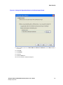
Installing Certificate Using Internet Explorer. . . . . . . . . . . . . . . . . . . . . . . . . . . . . . . . . . . 212
Summary Information . . . . . . . . . . . . . . . . . . . . . . . . . . . . . . . . . . . . . . . . . . . . . . . . . . . . 215
Alarm Information . . . . . . . . . . . . . . . . . . . . . . . . . . . . . . . . . . . . . . . . . . . . . . . . . . . . . . . 216
Call Log Status Information . . . . . . . . . . . . . . . . . . . . . . . . . . . . . . . . . . . . . . . . . . . . . . . 216
Telephony Status Information. . . . . . . . . . . . . . . . . . . . . . . . . . . . . . . . . . . . . . . . . . . . . . 217
MIB-II Status Information . . . . . . . . . . . . . . . . . . . . . . . . . . . . . . . . . . . . . . . . . . . . . . . . . 217
Version Information. . . . . . . . . . . . . . . . . . . . . . . . . . . . . . . . . . . . . . . . . . . . . . . . . . . . . . 218
Diagnostics Information . . . . . . . . . . . . . . . . . . . . . . . . . . . . . . . . . . . . . . . . . . . . . . . . . . 218
Diagnostics . . . . . . . . . . . . . . . . . . . . . . . . . . . . . . . . . . . . . . . . . . . . . . . . . . . . . . . . . . . . . . . . 219
9.1
9.2
9.3
9.4
9.5
9.6
9.7
VoIP Interface Test . . . . . . . . . . . . . . . . . . . . . . . . . . . . . . . . . . . . . . . . . . . . . . . . . . . . . . 219
9.1.1 VoIP Interface Test Overview . . . . . . . . . . . . . . . . . . . . . . . . . . . . . . . . . . . . . . . 219
9.1.2 VoIP Interface Test Operation . . . . . . . . . . . . . . . . . . . . . . . . . . . . . . . . . . . . . . . 220
TDM Interface Test . . . . . . . . . . . . . . . . . . . . . . . . . . . . . . . . . . . . . . . . . . . . . . . . . . . . . . 222
9.2.1 TDM Interface Test Overview . . . . . . . . . . . . . . . . . . . . . . . . . . . . . . . . . . . . . . . 222
9.2.2 TDM Interface Test Operation . . . . . . . . . . . . . . . . . . . . . . . . . . . . . . . . . . . . . . . 223
TDM Self Verification Test . . . . . . . . . . . . . . . . . . . . . . . . . . . . . . . . . . . . . . . . . . . . . . . . 226
9.3.1 TDM Self Verification Test Overview . . . . . . . . . . . . . . . . . . . . . . . . . . . . . . . . . . 226
9.3.2 TDM Self Verification Test Operation . . . . . . . . . . . . . . . . . . . . . . . . . . . . . . . . . 227
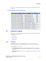
Diagnostic Logging . . . . . . . . . . . . . . . . . . . . . . . . . . . . . . . . . . . . . . . . . . . . . . . . . . . . . . 235
9.4.1 Overview . . . . . . . . . . . . . . . . . . . . . . . . . . . . . . . . . . . . . . . . . . . . . . . . . . . . . . . 235
9.4.2 Trace Capture . . . . . . . . . . . . . . . . . . . . . . . . . . . . . . . . . . . . . . . . . . . . . . . . . . . 236
9.4.3 Network Capture . . . . . . . . . . . . . . . . . . . . . . . . . . . . . . . . . . . . . . . . . . . . . . . . . 239
9.4.4 TDM Capture . . . . . . . . . . . . . . . . . . . . . . . . . . . . . . . . . . . . . . . . . . . . . . . . . . . . 241
Communicating to the Terminal Interface. . . . . . . . . . . . . . . . . . . . . . . . . . . . . . . . . . . . . 243
9.5.1 Connecting to Terminal Interface Via DIAGNOSTICS Connector . . . . . . . . . . . . 243
9.5.2 Connecting to Terminal Interface Via LAN Connector. . . . . . . . . . . . . . . . . . . . . 244
Trace Mechanism . . . . . . . . . . . . . . . . . . . . . . . . . . . . . . . . . . . . . . . . . . . . . . . . . . . . . . . 244
9.6.1 Trace Format . . . . . . . . . . . . . . . . . . . . . . . . . . . . . . . . . . . . . . . . . . . . . . . . . . . . 245
9.6.2 Trace Utility . . . . . . . . . . . . . . . . . . . . . . . . . . . . . . . . . . . . . . . . . . . . . . . . . . . . . 245
9.6.3 Trace Commands . . . . . . . . . . . . . . . . . . . . . . . . . . . . . . . . . . . . . . . . . . . . . . . . 248
9.6.4 Examples of Trace Commands and Displays . . . . . . . . . . . . . . . . . . . . . . . . . . . 250
Diagnostic Commands . . . . . . . . . . . . . . . . . . . . . . . . . . . . . . . . . . . . . . . . . . . . . . . . . . . 255
9.7.1 Devstat Command . . . . . . . . . . . . . . . . . . . . . . . . . . . . . . . . . . . . . . . . . . . . . . . . 255
9.7.2 Restart Command . . . . . . . . . . . . . . . . . . . . . . . . . . . . . . . . . . . . . . . . . . . . . . . . 255
9.7.3 Ping Command . . . . . . . . . . . . . . . . . . . . . . . . . . . . . . . . . . . . . . . . . . . . . . . . . . 255
9.7.4 Ver Command . . . . . . . . . . . . . . . . . . . . . . . . . . . . . . . . . . . . . . . . . . . . . . . . . . . 256
9.7.5 Alarm List Command . . . . . . . . . . . . . . . . . . . . . . . . . . . . . . . . . . . . . . . . . . . . . . 256
Index . . . . . . . . . . . . . . . . . . . . . . . . . . . . . . . . . . . . . . . . . . . . . . . . . . . . . . . . . . . . . . . . . . . . . . 257
8
Dialogic® 1000 and 2000 Media Gateway Series User’s Guide
Dialogic Corporation
Figures
1
2
3
4
5
6
7
8
9
10
11
12
13
14
15
16
17
18
19
20
21
22
23
24
25
26
27
28
29
30
31
32
33
34
35
36
37
38
39
40
41
Typical IP Gateway Phone Emulating Topology - PBX Connection . . . . . . . . . . . . . . . . . . . . . 23
Typical IP Gateway Phone Emulating Topology - PSTN Connection . . . . . . . . . . . . . . . . . . . . 23
IP Gateway Using Serial Link . . . . . . . . . . . . . . . . . . . . . . . . . . . . . . . . . . . . . . . . . . . . . . . . . . 24
Multiple IP Gateways Using Serial Link . . . . . . . . . . . . . . . . . . . . . . . . . . . . . . . . . . . . . . . . . . . 25
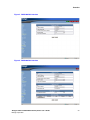
DMG1000 Web Interface . . . . . . . . . . . . . . . . . . . . . . . . . . . . . . . . . . . . . . . . . . . . . . . . . . . . . . 29
DMG2000 Web Interface . . . . . . . . . . . . . . . . . . . . . . . . . . . . . . . . . . . . . . . . . . . . . . . . . . . . . . 29
Example of a Network Topology . . . . . . . . . . . . . . . . . . . . . . . . . . . . . . . . . . . . . . . . . . . . . . . . 45
ISDN Call Type Rules Web Page . . . . . . . . . . . . . . . . . . . . . . . . . . . . . . . . . . . . . . . . . . . . . . 104
Manual Tones Web Page . . . . . . . . . . . . . . . . . . . . . . . . . . . . . . . . . . . . . . . . . . . . . . . . . . . . 141
Learn Tone Web Page. . . . . . . . . . . . . . . . . . . . . . . . . . . . . . . . . . . . . . . . . . . . . . . . . . . . . . . 143
VoIP to TDM calls . . . . . . . . . . . . . . . . . . . . . . . . . . . . . . . . . . . . . . . . . . . . . . . . . . . . . . . . . . 151
TDM to VoIP calls . . . . . . . . . . . . . . . . . . . . . . . . . . . . . . . . . . . . . . . . . . . . . . . . . . . . . . . . . . 152
Routing Table Call Routing Flow . . . . . . . . . . . . . . . . . . . . . . . . . . . . . . . . . . . . . . . . . . . . . . . 153
Inbound TDM Rules Configuration Web Page. . . . . . . . . . . . . . . . . . . . . . . . . . . . . . . . . . . . . 154
CPID Matching Configuration Web Page . . . . . . . . . . . . . . . . . . . . . . . . . . . . . . . . . . . . . . . . 156
Device Selection Configuration Web Page . . . . . . . . . . . . . . . . . . . . . . . . . . . . . . . . . . . . . . . 157
CPID Manipulation Configuration Web Page. . . . . . . . . . . . . . . . . . . . . . . . . . . . . . . . . . . . . . 158
Select Primary / Alternate Route Configuration Web Page . . . . . . . . . . . . . . . . . . . . . . . . . . . 159
Inbound VoIP Rules Configuration Web Page. . . . . . . . . . . . . . . . . . . . . . . . . . . . . . . . . . . . . 160
CPID Matching Configuration Web Page . . . . . . . . . . . . . . . . . . . . . . . . . . . . . . . . . . . . . . . . 162
Device Selection Configuration Web Page . . . . . . . . . . . . . . . . . . . . . . . . . . . . . . . . . . . . . . . 163
CPID Manipulation Configuration Web Page. . . . . . . . . . . . . . . . . . . . . . . . . . . . . . . . . . . . . . 164
Select Primary / Alternate Route Configuration Web Page . . . . . . . . . . . . . . . . . . . . . . . . . . . 165
TDM Trunk Groups Configuration Web Page . . . . . . . . . . . . . . . . . . . . . . . . . . . . . . . . . . . . . 166
VoIP Host Groups Configuration Web Page . . . . . . . . . . . . . . . . . . . . . . . . . . . . . . . . . . . . . . 168
Host List Configuration Web Page. . . . . . . . . . . . . . . . . . . . . . . . . . . . . . . . . . . . . . . . . . . . . . 168
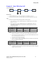
Inbound VOIP Route and Outbound Route . . . . . . . . . . . . . . . . . . . . . . . . . . . . . . . . . . . . . . . 169
Inbound TDM Route and Outbound Route . . . . . . . . . . . . . . . . . . . . . . . . . . . . . . . . . . . . . . . 170
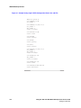
Default Analog CPID Configuration Data on Analog Web Page . . . . . . . . . . . . . . . . . . . . . . . 198
Default Analog CPID Configuration in the .ini File . . . . . . . . . . . . . . . . . . . . . . . . . . . . . . . . . . 199
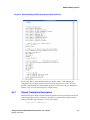
Sample Analog Type II CPID Configuration Data in the .adt File . . . . . . . . . . . . . . . . . . . . . . 200
Default Mitel Digital CPID Configuration Data (cpid.htm) . . . . . . . . . . . . . . . . . . . . . . . . . . . . 201
Storing Self-Signed Certificate by Certificate Import Wizard . . . . . . . . . . . . . . . . . . . . . . . . . . 213
VoIP Interface Web Page . . . . . . . . . . . . . . . . . . . . . . . . . . . . . . . . . . . . . . . . . . . . . . . . . . . . 220
VoIP Interface Test Status Web Page . . . . . . . . . . . . . . . . . . . . . . . . . . . . . . . . . . . . . . . . . . . 221
VoIP Interface Call Log Web Page . . . . . . . . . . . . . . . . . . . . . . . . . . . . . . . . . . . . . . . . . . . . . 222
TDM Interface Web Page . . . . . . . . . . . . . . . . . . . . . . . . . . . . . . . . . . . . . . . . . . . . . . . . . . . . 223
TDM Interface Test Status Web Page . . . . . . . . . . . . . . . . . . . . . . . . . . . . . . . . . . . . . . . . . . . 224
TDM Interface Call Log Web Page . . . . . . . . . . . . . . . . . . . . . . . . . . . . . . . . . . . . . . . . . . . . . 225
TDM Self Verification Web Page . . . . . . . . . . . . . . . . . . . . . . . . . . . . . . . . . . . . . . . . . . . . . . . 228
Call Flow for Initiate Call / Answer Call . . . . . . . . . . . . . . . . . . . . . . . . . . . . . . . . . . . . . . . . . . 230
Dialogic® 1000 and 2000 Media Gateway Series User’s Guide
Dialogic Corporation
9
Contents
42
43
44
45
46
47
48
49
50
51
52
53
54
55
56
10
Call Flow for Initiate Call / Answer Call and Transfer Call . . . . . . . . . . . . . . . . . . . . . . . . . . . . 231
Call Flow for Send Message Waiting Status . . . . . . . . . . . . . . . . . . . . . . . . . . . . . . . . . . . . . . 232
TDM Self Verification Test Status Web Page . . . . . . . . . . . . . . . . . . . . . . . . . . . . . . . . . . . . . . 232
TDM Self Verification Test Results . . . . . . . . . . . . . . . . . . . . . . . . . . . . . . . . . . . . . . . . . . . . . . 233
TDM Self Verification Call Log Web Page . . . . . . . . . . . . . . . . . . . . . . . . . . . . . . . . . . . . . . . . 235
Diagnostic Web Page . . . . . . . . . . . . . . . . . . . . . . . . . . . . . . . . . . . . . . . . . . . . . . . . . . . . . . . . 236
Trace Capture Control Page - DMG2000 . . . . . . . . . . . . . . . . . . . . . . . . . . . . . . . . . . . . . . . . . 237
Example of a Running Log - Trace Capture . . . . . . . . . . . . . . . . . . . . . . . . . . . . . . . . . . . . . . . 238
File Download Dialog Box for Trace.log . . . . . . . . . . . . . . . . . . . . . . . . . . . . . . . . . . . . . . . . . . 238
Network Capture Control Page - DMG2000 . . . . . . . . . . . . . . . . . . . . . . . . . . . . . . . . . . . . . . . 239
Example of Running Log - Network Capture . . . . . . . . . . . . . . . . . . . . . . . . . . . . . . . . . . . . . . 240
File Download Dialog Box for Iplog.pcap . . . . . . . . . . . . . . . . . . . . . . . . . . . . . . . . . . . . . . . . . 240
TDM Capture Control Web Page . . . . . . . . . . . . . . . . . . . . . . . . . . . . . . . . . . . . . . . . . . . . . . . 241
Example of Running Log - TDM Capture . . . . . . . . . . . . . . . . . . . . . . . . . . . . . . . . . . . . . . . . . 242
File Download Dialog Box for Tdmlog.wav . . . . . . . . . . . . . . . . . . . . . . . . . . . . . . . . . . . . . . . . 242
Dialogic® 1000 and 2000 Media Gateway Series User’s Guide
Dialogic Corporation
Tables
1
2
3
4
5
6
7
8
9
10
11
12
13
14
15
16
17
18
Coder/Decoder Parameters. . . . . . . . . . . . . . . . . . . . . . . . . . . . . . . . . . . . . . . . . . . . . . . . . . . . 69
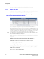
Syntax for Number Matching . . . . . . . . . . . . . . . . . . . . . . . . . . . . . . . . . . . . . . . . . . . . . . . . . . 104
Default Number Plan . . . . . . . . . . . . . . . . . . . . . . . . . . . . . . . . . . . . . . . . . . . . . . . . . . . . . . . . 105
Default Number Type. . . . . . . . . . . . . . . . . . . . . . . . . . . . . . . . . . . . . . . . . . . . . . . . . . . . . . . . 105
Syntax for Number Matching . . . . . . . . . . . . . . . . . . . . . . . . . . . . . . . . . . . . . . . . . . . . . . . . . . 106
Default Number Plan . . . . . . . . . . . . . . . . . . . . . . . . . . . . . . . . . . . . . . . . . . . . . . . . . . . . . . . . 106
Default Number Type. . . . . . . . . . . . . . . . . . . . . . . . . . . . . . . . . . . . . . . . . . . . . . . . . . . . . . . . 107
Syntax Used for CPID Matching . . . . . . . . . . . . . . . . . . . . . . . . . . . . . . . . . . . . . . . . . . . . . . . 155
Syntax Used for CPID Manipulation . . . . . . . . . . . . . . . . . . . . . . . . . . . . . . . . . . . . . . . . . . . . 158
Syntax for VoIP Host Address . . . . . . . . . . . . . . . . . . . . . . . . . . . . . . . . . . . . . . . . . . . . . . . . . 161
Syntax Used for CPID Matching . . . . . . . . . . . . . . . . . . . . . . . . . . . . . . . . . . . . . . . . . . . . . . . 161
Syntax Used for CPID Manipulation . . . . . . . . . . . . . . . . . . . . . . . . . . . . . . . . . . . . . . . . . . . . 163
TDM Port Types. . . . . . . . . . . . . . . . . . . . . . . . . . . . . . . . . . . . . . . . . . . . . . . . . . . . . . . . . . . . 166
Parser Regular Expressions . . . . . . . . . . . . . . . . . . . . . . . . . . . . . . . . . . . . . . . . . . . . . . . . . . 202
Parser Reason Codes . . . . . . . . . . . . . . . . . . . . . . . . . . . . . . . . . . . . . . . . . . . . . . . . . . . . . . . 204
Mapping of Protocol and Span Numbers to TDM Capture Channel Numbers . . . . . . . . . . . . 241
Supported Trace Keys . . . . . . . . . . . . . . . . . . . . . . . . . . . . . . . . . . . . . . . . . . . . . . . . . . . . . . . 246
Supported Trace Types . . . . . . . . . . . . . . . . . . . . . . . . . . . . . . . . . . . . . . . . . . . . . . . . . . . . . . 248
Dialogic® 1000 and 2000 Media Gateway Series User’s Guide
Dialogic Corporation
11
Contents
12
Dialogic® 1000 and 2000 Media Gateway Series User’s Guide
Dialogic Corporation
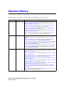
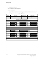
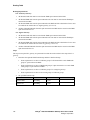
Revision History
This revision history summarizes the changes made in each published version of this document.
Document No.
Publication Date
Description of Revisions
64-0346-07
November 2009
Updated to support Version 6.0 SU3.2 Software.
Chapter 3, “Parameter Reference” updated parameter description for VoIP Host
Monitor Interval in Monitoring Group.
Chapter 3, “Parameter Reference” added note to Codec/Frame Size/Frames Per
Packet in Audio Group about DMG1000 with secure RTP (SRTP).
Chapter 3, “Parameter Reference” added new parameter in Non-Menu (Hidden)
Parameters for Incompatible Message STATUS.
Chapter 3, “Parameter Reference” added new parameter in Non-Menu (Hidden)
Parameters for ISDN Service Class.
Chapter 5, “Routing Table” updated screen shot and description in Inbound VoIP
Rules to show support for Move Row Up and Move Row Down buttons.
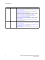
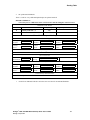
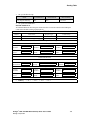
64-0346-05
May 2009
Updated to support Version 6.0 SU3.1 Software.
Chapter 3, “Parameter Reference” added new parameter in Timing Group for T1
Multiplier.
Chapter 3, “Parameter Reference” added new value Nortel_DMS-100 to ISDN
Protocol Variant in T1 ISDN Protocol Group (ISDN Signaling Mode).
Chapter 3, “Parameter Reference” added note to Enable Failover that this parameter
is only applicable for DMG2060DTISQ and DMG2120DTISQ models in T1 ISDN
Protocol Group (ISDN Signaling Mode).
Chapter 3, “Parameter Reference” added note to Enable Failover that this parameter
is only applicable for DMG2060DTISQ and DMG2120DTISQ models in E1 ISDN
Protocol Group (ISDN Signaling Mode).
64-0346-04
March 2009
Updated to support Version 6.0 SU3 Software.
Chapter 3, “Parameter Reference” added new parameter in User-Agent Group for
Reliable Provisional Responses.
Chapter 3, “Parameter Reference” added new parameter in TLS Group for Verify TLS
Peer Certificate Purpose.
Chapter 3, “Parameter Reference” added new parameter in T1 CAS Protocol Group
(T1 CAS Signaling Mode) for Inband Type I CID to First Ring Timeout.
Chapter 3, “Parameter Reference” added new parameter in CPID Settings Group for
CID to First Ring Timeout.
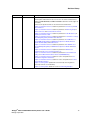
Chapter 3, “Parameter Reference” added new parameter in T1 ISDN Protocol Group
(ISDN Signaling Mode) for Multiple Diversion Processing.
Chapter 3, “Parameter Reference” added new parameter in E1 ISDN Protocol Group
(ISDN Signaling Mode) for Multiple Diversion Processing.
Chapter 3, “Parameter Reference” added new parameters in Non-Menu (Hidden)
Parameters for SIP Phone Context From, SIP Phone Context To, and SIP User
Phone Enabled.
Chapter 8, “Unit Status” removed details from MIB-II Status Information section and
replaced with link to SNMP Application Note.
Dialogic® 1000 and 2000 Media Gateway Series User’s Guide
Dialogic Corporation
13
Revision History
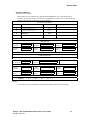
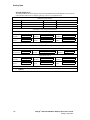
Document No.
Publication Date
64-0346-03
January 2009
Description of Revisions
Updated to support Version 6.0 SU2 Software.
Chapter 3, “Parameter Reference” added new parameter in User-Agent Group for
Reliable Provisional Responses.
Chapter 3, “Parameter Reference” updated parameter to Default Value = Off for
Signaling Digit Relay Mode in Audio Group.
Chapter 3, “Parameter Reference” updated parameter to remove the statement
“Early Media is supported for VoIP to TDM calls only” since it is now supported in
both directions for RFC 3960 Early Media Support in Audio Group.
Chapter 3, “Parameter Reference” added new parameter in TDM General
Parameters for Connect Outbound Call On DTMF.
Chapter 3, “Parameter Reference” updated parameter to include more supported
Allowed Values for Network Specific Facilities (NSF) in T1 ISDN Protocol Group
(ISDN Signaling Mode).
Chapter 3, “Parameter Reference” added new TDM Call Type Group section to
support call type per call feature.
64-0346-02
September 2008
Updated to support Version 6.0 SU1 Software.
Chapter 3, “Parameter Reference” updated parameter description for Signaling Digit
Relay Mode in Audio Group.
Chapter 3, “Parameter Reference” added new parameter in T1 CAS Protocol Group
(T1 CAS Signaling Mode) for Transfer Feature Code.
Chapter 3, “Parameter Reference” added new parameter in Feature Code Group for
Transfer Feature Code.
14
Dialogic® 1000 and 2000 Media Gateway Series User’s Guide
Dialogic Corporation
Revision History
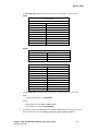
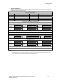
Document No.
Publication Date
Description of Revisions
64-0346-01
March 2008
Updated to support Version 6.0 Software.
Global Updates: Added and revised screen shots for the enhanced Web interface.
Added new DMG2060DTISQ and DMG2120DTISQ models which include support for
survivability.
Removed some parameters that are obsoleted in Version 6.0 Software.
Chapter 3, “Parameter Reference” added new parameter in Server Group for DNS
Server Address 2.
Chapter 3, “Parameter Reference” added new parameters in Monitoring Group for
Monitor VoIP Hosts and VoIP Host Monitor Interval.
Chapter 3, “Parameter Reference” added new parameter in T1/E1 Mode Group for
Telephony Port Interface Side.
Chapter 3, “Parameter Reference” added new parameter in T1 CAS Protocol Group
(T1 CAS Signaling Mode) for Enable Glare Detection.
Chapter 3, “Parameter Reference” added new parameters in T1 ISDN Protocol
Group (ISDN Signaling Mode) for ISDN Answer Supervision Enable, Network
Specific Facilities (NSF), and Enable Failover.
Chapter 3, “Parameter Reference” added new parameters in E1 ISDN Protocol
Group (ISDN Signaling Mode) for ISDN Answer Supervision Enable and Enable
Failover.
Chapter 3, “Parameter Reference” added new parameter in TDM General
Parameters for Disconnect on Fax Cleardown Tone.
Chapter 3, “Parameter Reference” added new parameter in T.38 Fax Advanced
Settings for Fax Modem Carrier Detect Threshold (DMG1000 Only).
Chapter 3, “Parameter Reference” added new section and parameters in Tone
Generation Configuration Parameters.
Chapter 3, “Parameter Reference” added new section and parameters in Positive
Answer Machine Detection.
Chapter 5, “Routing Table” updated with new functionality and configurations
(previously referred to as the Dial Plan).
Chapter 5, “Routing Table” added new section for Call Routing Examples.
Dialogic® 1000 and 2000 Media Gateway Series User’s Guide
Dialogic Corporation
15
Revision History
16
Dialogic® 1000 and 2000 Media Gateway Series User’s Guide
Dialogic Corporation
About This Publication
The following topics provide information about this guide:
• Purpose
• Intended Audience
• How to Use This Publication
• Related Information
Purpose
This document provides information about installing, configuring, operating, and maintaining the
Dialogic® Media Gateway.
Intended Audience
This information is intended for:
• Distributors
• System Integrators
• Value Added Resellers (VARs)
• Original Equipment Manufacturers (OEMs)
How to Use This Publication
This information is organized as follows:
• Chapter 1, “Overview” provides a description of the product and discusses call routing,
address translation, and the Web interface.
• Chapter 2, “Media Gateway Configuration” provides procedures for configuring and
upgrading the Media Gateway.
• Chapter 3, “Parameter Reference” lists the Media Gateway parameters that can be configured
from the Web interface.
• Chapter 4, “Call Progress Tones” describes how to view, edit, learn, and validate call progress
tones from the Web interface.
• Chapter 5, “Routing Table” describes a set of rules used to define the characteristics of a call
routed through the Media Gateway.
Dialogic® 1000 and 2000 Media Gateway Series User’s Guide
Dialogic Corporation
17
About This Publication
• Chapter 6, “Media Gateway Parsers” describes the Media Gateway in-band Type I (on-hook)
and Type II (off-hook) integration parsers for analog units, and the display parser for digital
units. These parsers allow the user to define the meaning of either the in-band/on-hook
integration strings or display strings received from the telephony network.
• Chapter 7, “Data Security” provides information about configuring security on the Media
Gateway for HTTP, call control, and voice.
• Chapter 8, “Unit Status” describes the various types of status information that may be obtained
about the Media Gateway.
• Chapter 9, “Diagnostics” provides information about using diagnostic logging, running the
diagnostic tests, and using the various terminal commands to perform diagnostics on the
Media Gateway.
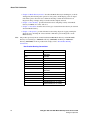
Note:
The products previously known as Intel NetStructure PBX-Media Gateway and T1/E1-Media
Gateway are now Dialogic® 1000 Media Gateway (DMG1000) and Dialogic® 2000 Media
Gateway (DMG2000). For more product name changes, refer to New Product Naming
Conventions.
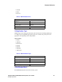
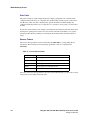
New Product Naming Conventions
Previous Name
PBX-IP Media Gateway
New Name
Dialogic®
1000 Media Gateway
(DMG1000)
PIMG
DMG1000
PIMG40LS
DMG1004LSW
PIMG80LS
DMG1008LSW
PIMG80DNI
DMG1008DNIW
PIMG80MTLDNI
DMG1008MTLDNIW
PIMG80RLMDNI
DMG1008RLMDNIW
T1/E1-IP Media Gateway
Dialogic® 2000 Media Gateway
(DMG2000)
TIMG
DMG2000
TIMG300DTI
DMG2030DTIQ
TIMG600DTI
DMG2060DTIQ
TIMG1200DTI
DMG2120DTIQ
DMG2060DTISQ (with survivability)
DMG2120DTISQ (with survivability)
18
Dialogic® 1000 and 2000 Media Gateway Series User’s Guide
Dialogic Corporation
About This Publication
Related Information
For additional information related to the Dialogic® 1000 Media Gateway (DMG1000) and
Dialogic® 2000 Media Gateway (DMG2000) products, see the following:
• Dialogic® 1000 and 2000 Media Gateway Series Getting Started Guide for information about
installing, cabling, and initializing the product prior to performing configuration and operation
tasks.
• Dialogic® Media Gateway Installation and Configuration Integration Notes for details on
typical installation and configuration of Media Gateway when used to interface between PBX
and unified messaging application.
• http://www.dialogic.com/manuals/ (for Dialogic® product documentation)
• http://www.dialogic.com/support/ (for Dialogic technical support)
• http://www.dialogic.com/ (for Dialogic® product information)
Dialogic® 1000 and 2000 Media Gateway Series User’s Guide
Dialogic Corporation
19
About This Publication
20
Dialogic® 1000 and 2000 Media Gateway Series User’s Guide
Dialogic Corporation
Overview
1
The following information provides an overview of the Dialogic® Media Gateway:
• Product Description . . . . . . . . . . . . . . . . . . . . . . . . . . . . . . . . . . . . . . . . . . . . . . . . . . . . 21
• Call Routing in Phone Emulating Mode . . . . . . . . . . . . . . . . . . . . . . . . . . . . . . . . . . . . 26
• Voice over IP Address Translation . . . . . . . . . . . . . . . . . . . . . . . . . . . . . . . . . . . . . . . . 27
• Security . . . . . . . . . . . . . . . . . . . . . . . . . . . . . . . . . . . . . . . . . . . . . . . . . . . . . . . . . . . . . 28
• Web Interface. . . . . . . . . . . . . . . . . . . . . . . . . . . . . . . . . . . . . . . . . . . . . . . . . . . . . . . . . 28
• Online Help . . . . . . . . . . . . . . . . . . . . . . . . . . . . . . . . . . . . . . . . . . . . . . . . . . . . . . . . . . 31
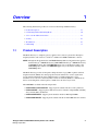
1.1
Product Description
The Media Gateway is a telephony gateway appliance that connects to phone lines through its
telephony interface and connects to a LAN via a 10 BaseT or 100 BaseT Ethernet connector.
NOTE: Throughout this document, the term Media Gateway addresses information that applies to
both the Dialogic® 1000 Media Gateway (DMG1000) and Dialogic® 2000 Media Gateway
(DMG2000) products. The term DMG1000 applies only to information relating to the
DMG1000 product and the term DMG2000 applies only to information relating to the
DMG2000 product.
The Media Gateway provides an inexpensive bridge between a legacy PBX or public switched
telephone network (PSTN) and a managed packet network. This device converts signals from
circuit switched equipment into Session Initiation Protocol (SIP) standard protocol for
transmission over a local area network (LAN) or wide area network (WAN) to communications
devices such as IP phones, wireless phones, and IP servers in almost any location.
The DMG1000 is available in the following models:
• DMG1008LSW, DMG1004LSW - Supports phone emulation mode for analog interfaces.
• DMG1008DNIW - Supports phone emulation mode for a number of digital PBXs, including
Avaya, Nortel, NEC, and Siemens.
• DMG1008MTLDNIW - Supports phone emulation mode for Mitel digital PBXs.
• DMG1008RLMDNIW - Supports phone emulation mode for Rolm 8000 and 9751 switches.
Dialogic® 1000 and 2000 Media Gateway Series User’s Guide
Dialogic Corporation
21
Overview
The DMG2000 is available in the following models:
• DMG2030DTIQ - Supports phone emulation mode for a single T1 or E1 interface.
• DMG2060DTIQ - Supports phone emulation mode for two T1 or E1 interfaces.
• DMG2120DTIQ - Supports phone emulation mode for four T1 or E1 interfaces.
• DMG2060DTISQ - Supports phone emulation mode with survivability for two T1 or E1
interfaces.
• DMG2120DTISQ - Supports phone emulation mode with survivability for four T1 or E1
interfaces.
Note:
The Item Market Name on the Media Gateway may vary slightly, depending on the version.
Depending on the model, the Media Gateway can be configured for the following operating mode:
• Phone Emulating
1.1.1
Phone Emulating
In the Phone Emulating mode, the Media Gateway operates as a telephony gateway appliance that
emulates the following for transporting PBX functionality over a packet-switched network:
• up to eight station sets (DMG1000 models)
• up to 24 station sets (single T1 DMG2000 model)
• up to 48 station sets (dual T1 DMG2000 model)
• up to 96 station sets (quad T1 DMG2000 model)
• up to 30 station sets (single E1 DMG2000 model)
• up to 60 station sets (dual E1 DMG2000 model)
• up to 120 station sets (quad E1 DMG2000 model)
The Media Gateway translates protocols for call setup and release between the IP network and the
PBX or PSTN, and converts the media formats between the two networks.
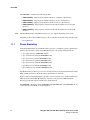
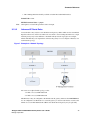
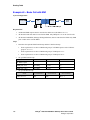
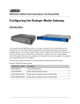
Figure 1 shows how the Media Gateway provides a gateway between voice over IP (VoIP) devices
(SIP) on a LAN and the PBX. By emulating station sets to the proprietary PBX, the Media
Gateway provides full call party information to the IP network.
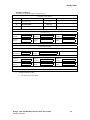
The DMG2000 or the analog version (DMG1008LSW, DMG1004LSW) of the DMG1000 can also
connect directly to the PSTN, as shown in Figure 2.
22
Dialogic® 1000 and 2000 Media Gateway Series User’s Guide
Dialogic Corporation
Overview
Figure 1. Typical IP Gateway Phone Emulating Topology - PBX Connection
PSTN
VoIP
Terminal
Device
Digital
Telephone
Media Gateway
(All Phone Emulating Models)
Digital PBX
1-8
Digital
Phone
Lines
or
1-4
T1/E1 Trunks
Digital
Telephone
VoIP
Terminal
Device
LAN
Figure 2. Typical IP Gateway Phone Emulating Topology - PSTN Connection
VoIP
Terminal
Device
DMG1008LSW
DMG1000 Media Gateway
or
DMG2000 Media Gateway
PSTN
1 - 8 Analog
Phone Lines
or
1 - 4 T1/E1
Trunks
Note: The T1/E1 Models must only be connected to
the PSTN through an NTU, CSU or other
device that provides line isolation.
1.1.1.1
VoIP
Terminal
Device
LAN
Serial Protocol Support in Phone Emulating Mode
By emulating telephone sets to the switch, the Media Gateway provides call party information over
the IP network. However, the amount of call party information that the Media Gateway can provide
is limited to the amount of data that the switch provides its station sets. Some proprietary switches
Dialogic® 1000 and 2000 Media Gateway Series User’s Guide
Dialogic Corporation
23
Overview
provide full call party information across the station set interfaces while others provide little or no
call party information across the station set interface. The PBX switches that provide little or no
call party information typically will provide full call party information across a separate serial
interface connection.
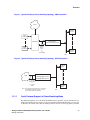
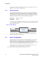
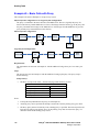
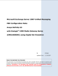
For this reason, the Media Gateway supports a serial link interface to the switch or PSTN, and
supports several serial protocols. Figure 3 shows how the Media Gateway connects to a switch or
PSTN that uses a serial link to provide call party information. Using this serial link, the Media
Gateway is able to provide full call party information on a PBX switch or PSTN that provides little
or no call party information via their station set interfaces.
Figure 3. IP Gateway Using Serial Link
VoIP
Terminal
Device
Note: Only the Analog and T1/E1 Models
can connect to the PSTN.
PSTN
Serial Link
Media Gateway
(Phone Emulating)
Digital PBX
1-8
Phone Lines
or
1 - 4 T1/E1
Trunks
Note: The T1/E1 Models must only be connected to
the PSTN through an NTU, CSU or other
device that provides line isolation.
VoIP
Terminal
Device
LAN
When a call arrives at a telephony port on the Media Gateway, the switch or PSTN will send a data
packet across the serial link containing the call party information associated with the call. If
configured to use the serial interface, the Media Gateway will use the data in the serial packet as the
call party information when the call notification is sent across the IP network to the VoIP terminal
device that the call is intended for - superseding any call information that may have arrived across
the station set interface. Finally, the serial protocols also support the message waiting indication
(MWI) feature that allows the Media Gateway to control message indications on telephone sets
connected to the switch or PSTN.
For DMG1000 types, the serial link from the switch is connected to the serial port interface on the
DMG1000 (DIAGNOSTICS connector). Table 1, “DIAGNOSTICS Connector Pin Designations”
in the Getting Started Guide shows the connector pin designations.
For DMG2000 types, the serial link from the switch is connected to the serial port interface on the
DMG2000 (COM 1 or COM 2 connector). Table 4, “COM 1 and COM 2 Connector Pin
Designations” in the Getting Started Guide shows the connector pin designations.
24
Dialogic® 1000 and 2000 Media Gateway Series User’s Guide
Dialogic Corporation
Overview
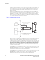
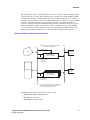
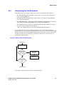
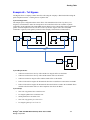
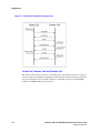
The switch only provides a single serial link connection. At a site where there are multiple Media
Gateway units, only one of the units can be physically connected to the switch or PSTN serial link.
This unit is the serial protocol Master Media Gateway while the remaining units are considered
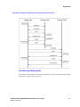
serial protocol slaves. Figure 4 shows how multiple Media Gateways connect to a switch or PSTN
that uses a serial link to provide call party information. It is the responsibility of the Master
gateway to send all serial link data intended for Slave Gateways to the Slave Gateways across the
IP network. Similarly, anytime a Slave Gateways needs to communicate to the switch or PSTN
across the serial link, the slave unit sends the data across the IP link to the Master Gateway. The
Master Gateway will then send the data across the serial link on behalf of the slave device.
Figure 4. Multiple IP Gateways Using Serial Link
Note: Only the Analog and T1/E1 Models
can connect to the PSTN.
LAN
Serial Link
VoIP
Terminal
Device
PSTN
Media Gateway
(Phone Emulating)
1 - 8 Phone Lines
or 1 - 4
T1/E1 Lines
Master Gateway
VoIP
Terminal
Device
Digital PBX
Media Gateway
(Phone Emulating)
1 - n Phone Lines
or T1/E1 Lines
Slave Gateways
Note: The T1/E1 Models must only be connected to
the PSTN through an NTU, CSU or other
device that provides line isolation.
The Media Gateway supports the following serial protocols:
• SMDI (Simple Message Desk Interface)
• MCI (NEC Systems only)
• MD110 (Ericsson Systems only)
Dialogic® 1000 and 2000 Media Gateway Series User’s Guide
Dialogic Corporation
25
Overview
Both the serial interface and the selection of which serial protocol to use are configurable using the
Web interface. Refer to Chapter 3, “Parameter Reference” for information about configuring the
serial interface and serial protocols.
1.2
Call Routing in Phone Emulating Mode
The Media Gateway routes calls from the Switch network to a VoIP destination on the IP network.
Conversely, it routes calls from the IP network through a Switch port to a destination telephone
number on the Switch network. The Media Gateway supports the following call routing options:
• User configurable list of VoIP Servers
• IP load Balancing
• IP Fault Tolerance
In its simplest form, call routing is supported by configuring a single VoIP Server to receive and/or
originate calls through the Media Gateway. In this manner, all inbound Switch-to-IP calls will be
sent to the single user configured VoIP endpoint. For IP-to-Switch calls, the telephony port will be
selected in a round robin fashion – where each IP-to-Switch call will be routed to the next available
telephony port.
If the user configures more than one VoIP Server to receive and/or originate calls through the
Media Gateway, then the user has the option to have the incoming Switch-to-IP calls load balanced
between the configured VoIP Servers. Specifically, incoming Switch calls will be routed to a VoIP
server in a round-robin fashion. For example, if there are three (3) VoIP Servers configured, the
first call will be routed to the first VoIP server, the second call will be routed to the second VoIP
server, the third call will be routed to the third VoIP server. The next call will be routed to the first
VoIP Server and the process will start all over again. IP-to-Switch calls are handled in the same
way when multiple VoIP Servers are configured as when only a single VoIP server is configured
(e.g. in a round robin fashion).
If the user configures more than one VoIP Server to receive and/or originate calls through the
Media Gateway, then the user has the option to support fault tolerance on the incoming Switch-toIP calls. Specifically, if the VoIP server fails to respond to incoming Switch call (or responds with
an error), the Media Gateway will route the call to the next VoIP Server in the user configurable list
of VoIP Servers.
Note:
1.2.1
If both IP Load Balancing and Fault Tolerance are enabled, then incoming IP-to-Switch calls will
be routed to the configured VoIP Servers in a round robin fashion and, if at any time a VoIP Server
fails to respond or responds with any error, the Media Gateway will route the call to the next
available VoIP Server.
Un-Routable Calls
A call is un-routable by the Media Gateway if the unit is unable to route the call to the other
network. This may occur if there is insufficient destination address information to determine a
destination for the call, or if there are not enough free resources on the Media Gateway to route the
call. The Media Gateway provides a number of different ways to handle these conditions in order to
insure that no calls are dropped or not completed.
26
Dialogic® 1000 and 2000 Media Gateway Series User’s Guide
Dialogic Corporation
Overview
1.2.1.1
IP to Switch Calls
There are a few circumstances where an inbound IP call may not be routed to the Switch network.
They are the following:
• No available Switch Ports
– There are no available Media Gateway Switch ports on which to carry the call.
• Invalid or No Switch destination address specified
– The IP call information does not contain a valid E.164 destination address for the Switch
network.
The administrator may specify a default destination IP address that is to receive any inbound IP
calls that cannot be routed to the Switch. If the administrator specifies a default destination IP
address for un-routable IP calls, then any inbound IP call that cannot be routed to the Switch
network is handled in the Routing Table as alternate routes.
1.2.1.2
Switch to IP Calls
There are a few circumstances in which an inbound Switch call may not be routed to the IP
network. They are the following:
• IP destination not configured.
• IP destination not present.
The administrator may specify a default destination Switch extension that is to receive any inbound
Switch calls that cannot be routed to the IP network. If the administrator specifies a default
destination Switch extension for un-routable Switch calls, then any inbound Switch call that cannot
be routed to the IP network is handled in the Routing Table as alternate routes.
1.3
Voice over IP Address Translation
The Voice over IP (VoIP) Address Translator provides network services to SIP devices such as the
Media Gateway. SIP devices register with the VoIP Address Translator to sent and receive SIP
calls.
The VoIP Address Translator can provide network services such as:
• Controlling the number and type of connections allowed across the network.
• Helping to route a call to the correct destination.
• Determining and maintaining the network address for incoming calls.
Without a VoIP Address Translator, all IP destination addresses must be specified to the Media
Gateway as IP v4 addresses (e.g. 10.10.4.128). IP terminal devices must also explicitly specify the
IP address of the Media Gateway as the desired gateway when originating PBX calls.
With a VoIP Address Translator, IP destination addresses may be specified to the Media Gateway
as e-mail addresses, alphanumeric aliases, E.164 telephone numbers, domain names, and any other
format supported by the VoIP Address Translator. IP terminal devices may explicitly specify the IP
Dialogic® 1000 and 2000 Media Gateway Series User’s Guide
Dialogic Corporation
27
Overview
address of the Media Gateway as the desired gateway, or they may rely on the VoIP Address
Translator to address the Media Gateway using the gateway prefix configured on the Media
Gateway.
1.4
Security
The Media Gateway supports two kinds of security:
• Access Security
• Data Security
1.4.1
Access Security
Access to the Media Gateway is secured by requiring a user name and password to login to the
gateway. The user name and password are required for all interfaces of the Media Gateway (Web
interface, serial interface, and telnet interface).
1.4.2
Data Security
Data security for the Media Gateway includes the use of various secure protocols when
transmitting and receiving data. The Media Gateway supports security for three types of data:
• HTTP security - Data transmitted between the Media Gateway and a Web browser. To secure
HTTP, the Media Gateway uses HTTPS protocol.
• Call Control security - Data used to setup and tear down a call. To secure Call Control, the
Media Gateway uses Transport Layer Security (TLS) on top of SIP.
• Voice security - The actual conversation once a call is connected. To secure voice, the Media
Gateway uses SRTP.
Because, for security, the HTTPS and TLS protocols also require digital identity certificates (e.g.
public key certificates), Certificate Configuration and Management is also provided by the Media
Gateway.
For additional information about how the Media Gateway supports security, see Chapter 7, “Data
Security”.
1.5
Web Interface
The Web interface is accessed from a workstation on the Ethernet connected to the LAN connector
on the rear panel of the Media Gateway. Communication is established by starting a Web browser
at the workstation and entering the IP address of the Media Gateway. The unit's Web interface is
password protected and the password can be changed by the system administrator. Figure 5 shows
a typical Web interface page for a DMG1000 unit and Figure 6 shows a typical Web interface page
for a DMG2000 unit.
28
Dialogic® 1000 and 2000 Media Gateway Series User’s Guide
Dialogic Corporation
Overview
Figure 5. DMG1000 Web Interface
Figure 6. DMG2000 Web Interface
Dialogic® 1000 and 2000 Media Gateway Series User’s Guide
Dialogic Corporation
29
Overview
The Media Gateway’s Web interface is divided into four sections, Status, Configuration,
Diagnostics, and System.
The Status Web pages provide run-time information and statistics about the operation of the unit.
The Diagnostics Web pages provide the system administrator with an interface to perform
diagnostics tasks.
The Configuration Web pages provide the system administrator with an interface to configure the
Media Gateway. The Configuration menu selections include:
• Import/Export - Selecting Import/Export brings up the Import/Export Web page which
allows you to save a copy of your current configuration (Export) to a directory on the
computer or to import a configuration file to the Media Gateway (Import). For information
about exporting a configuration file, see Section 2.6.1, “Exporting Configuration
Information”, on page 37. For information about importing a configuration file, see
Section 2.6.2, “Importing Configuration Information”, on page 38.
• IP - Selecting IP brings up the IP Web page which allows you to configure the IP parameters.
For detailed information about the IP parameters, see Section 3.1, “IP Settings”, on page 41.
• Management Protocols - Selecting Management Protocols brings up the Management
Protocols Web page which allows you to configure E-mail, Syslog, SNMP, Web Server, and
Telnet parameters. For detailed information about the Management Protocols parameters, see
Section 3.2, “Management Protocols Parameters”, on page 47.
• Routing Table - Selecting Routing Table brings up the Routing Table Web page which allows
you to configure a set of rules used to define the characteristics of a call routed through the
gateway. For detailed information about the Routing Table, see Section 5.2, “Router
Configuration”, on page 152.
• VoIP - Selecting VoIP brings up the VoIP Web page which allows you to configure VoIP
parameters. For detailed information about the VoIP parameters, see Section 3.3, “VoIP
General Parameters”, on page 53.
• TDM - Selecting TDM brings up the TDM Web page which allows you to configure TDM
parameters. Some of these parameters differ, depending on the different DMG1000 and
DMG2000 models. For detailed information about the TDM parameters, see Section 3.6,
“TDM General Parameters”, on page 75.
• Serial Ports - Selecting Serial Ports brings up the Serial Ports Web page. This Web page
allows you to configure the serial protocol for the Media Gateway serial port. See
Section 3.13, “Serial Ports Parameters”, on page 107 for detailed information about the Serial
Ports parameters.
• Tone Detection - Selecting Tones allows you to manipulate call progress tone parameters.
These parameters define the characteristics (frequencies, durations, and deviations) of the
tones that the Media Gateway detects during call progress analysis. For more information, see
Section 3.15, “Tone Detection Parameters”, on page 114 and Chapter 4, “Call Progress
Tones”.
• Certificates - Selecting Certificates brings up the Certificates Web page which allows you to
configure Certificates parameters. For detailed information about the Certificates parameters,
see Section 3.16, “Certificates Parameters”, on page 121.
30
Dialogic® 1000 and 2000 Media Gateway Series User’s Guide
Dialogic Corporation
Overview
• DSP Settings - Selecting DSP Settings brings up the DSP Settings Web page which allows
you to configure DSP Settings parameters. For detailed information about the DSP Settings
parameters, see Section 3.17, “DSP Settings Parameters”, on page 122.
The System Web pages provide the system administrator with an interface to change password,
upgrade system, and restart system.
• Password - Selecting Password brings up the Password Web page. This page allows you to
change your password. For information about the procedure for changing your password, see
Section 2.3, “Changing the Password”, on page 35.
• Upgrade - Selecting Upgrade brings up the Upgrade Web page. The Upgrade Web page
allows you to upgrade the Media Gateway software. For information about the procedure for
upgrading the software, see Section 2.7, “Upgrading the Software”, on page 38.
• Restart - Selecting Restart from the Configuration menu brings up the Restart Web page
which allows you to restart the Media Gateway. Restarting the unit is required when certain
parameter values are changed. You have two options to choose from when restarting the unit:
– Restart Unit Now - Clicking this button will cause the unit to restart immediately.
– Restart Unit When Idle - Clicking this button will cause the unit to restart when the unit is
considered in the idle state. In the idle state, there are no calls (incoming, outgoing, or
connected) on any of the PBX ports of the Media Gateway. By selecting this option, you
will schedule a restart time that minimizes the effect the restart will have on call traffic
through the unit.
1.6
Online Help
Context-sensitive online Help is provided for the various Web pages. When you move the mouse
pointer over a parameter name, the pointer changes from an arrow to a “?” symbol and Help
information about that parameter is displayed at the top of the page.
Dialogic® 1000 and 2000 Media Gateway Series User’s Guide
Dialogic Corporation
31
Overview
32
Dialogic® 1000 and 2000 Media Gateway Series User’s Guide
Dialogic Corporation
Media Gateway Configuration
2
Information about configuring, and upgrading the Dialogic® 1000 Media Gateway (DMG1000)
and Dialogic® 2000 Media Gateway (DMG2000) is contained in the following sections:
• Setting the IP Address . . . . . . . . . . . . . . . . . . . . . . . . . . . . . . . . . . . . . . . . . . . . . . . . . . 33
• Basic Configuration Via the Serial Port . . . . . . . . . . . . . . . . . . . . . . . . . . . . . . . . . . . . 34
• Changing the Password . . . . . . . . . . . . . . . . . . . . . . . . . . . . . . . . . . . . . . . . . . . . . . . . . 35
• Configuration Procedure . . . . . . . . . . . . . . . . . . . . . . . . . . . . . . . . . . . . . . . . . . . . . . . . 35
• Restart Options . . . . . . . . . . . . . . . . . . . . . . . . . . . . . . . . . . . . . . . . . . . . . . . . . . . . . . . 36
• Importing and Exporting Configuration Information . . . . . . . . . . . . . . . . . . . . . . . . . . 36
• Upgrading the Software. . . . . . . . . . . . . . . . . . . . . . . . . . . . . . . . . . . . . . . . . . . . . . . . . 38
Note:
2.1
Refer to the Getting Started Guide for information about initially logging on to the Media Gateway
and performing basic configuration via the serial port.
Setting the IP Address
Once the IP address of the Media Gateway unit has been configured through the Web interface, the
unit must be restarted to activate the new configuration. The Media Gateway unit will then be
accessible to the Web browser at the newly configured IP address. All configuration parameters are
saved in the Media Gateway’s non-volatile memory.
Use the following steps to assign the Media Gateway a unique IP address:
1. Select the IP configuration Web page from the Configuration menu on the left side of the
Web page.
2. Change the unit's IP address from the default address by entering the new IP address in the
Client IP Address box.
3. Configure the subnet mask if it is different from the default value by entering the new subnet
mask in the Client Subnet Mask box.
4. Configure the IP address of the default network gateway router by entering the IP address in
the Default Network Gateway Address box.
5. Click on the Apply Changes button to save the configuration in the database.
Note:
Refer to Chapter 3, “Parameter Reference” for a description of all of the configuration parameters
that may be changed.
6. For the configuration change to take effect, you will be prompted to restart the Media Gateway
by clicking on Restart on the Web page or by selecting Restart from the Configuration menu.
7. When the Restart Web page appears, click on Restart Unit Now to restart the Media
Gateway.
Dialogic® 1000 and 2000 Media Gateway Series User’s Guide
Dialogic Corporation
33
Media Gateway Configuration
8. Once the system completes its initialization (after approximately one minute), browse to the
new IP address. The Web browser can now access the unit at the new IP address.
9. If it was necessary to change the IP address of your Windows® workstation in the Initial Log
On procedure (described in the Getting Started Guide), you should now change it back to the
original IP address and access the Media Gateway using the Media Gateway’s newly
configured IP address.
10. You must now log on to the system again. After logging on, the Summary Web page will now
appear. You may now select any item from the Status or Configuration menu.
2.2
Basic Configuration Via the Serial Port
When the default IP address is unreachable (or if a previously configured IP address becomes
unreachable) on your network, use the following procedure to set the Client IP Address, Client
Subnet Mask, Default Network Gateway Address, Operating Mode, and PBX Type parameters of
the Media Gateway:
1. Connect a serial cable to the serial connector on the rear panel of the Media Gateway unit
(DIAGNOSTICS connector on the DMG1000 models or the COM 2 connector on the
DMG2000 models). For connector pin designation information, refer to the DIAGNOSTICS
Connector Pin Designations table or the COM 1 and COM 2 Connector Pin Designations table
in the Getting Started Guide.
2. Using a standard serial interface application (for example, Procomm Plus or HyperTerminal),
set the workstation to the following:
• Baud Rate = 38400 (DMG1000) or 115200 (DMG2000) bps
• Parity = None
• Data Bits = 8
• Stop Bits = 1
• Hardware Flow Control = Off
3. Press the Enter key repeatedly until the following prompt appears:
PIMG>
4. At the prompt, type pwd and press Enter.
5. When prompted, enter the password for the admin user (the default is IpodAdmin) and press
Enter.
6. At the prompt, type quickcfg and press Enter.
7. You will then be prompted to enter the following Media Gateway parameter information:
• Client IP Address (See Client IP Address parameter information in Section 3.1, “IP
Settings”, on page 41.)
• Client Subnet Mask (See Client Subnet Mask parameter information in Section 3.1, “IP
Settings”, on page 41.)
• Network Gateway IP (if required) (See Default Network Gateway Address parameter
information in Section 3.1, “IP Settings”, on page 41.)
34
Dialogic® 1000 and 2000 Media Gateway Series User’s Guide
Dialogic Corporation
Media Gateway Configuration
• For DMG1000 models, select Telephony Switch Type (See Telephony Switch Type
parameter information in Section 3.9, “TDM Digital Parameters”, on page 101.)
Note:
The Telephony Switch Type parameter does not apply to the Models DMG1008MTLDNIW,
DMG1008LSW, DMG1004LSW, DMG2030DTIQ, DMG2060DTIQ, and DMG2120DTIQ.
• For DMG2000 models, select:
– Line Mode (Section 3.7.1.1, “Line Mode”, on page 79)
– CAS Protocol (Section 3.7.1.2, “Signaling Mode”, on page 79 and Section 3.7.2.1,
“T1 CAS Protocol”, on page 80) or ISDN Protocol (Section 3.7.1.2, “Signaling
Mode”, on page 79 and Section 3.7.3.4, “ISDN Protocol”, on page 87)
8. When prompted that the parameters have been successfully configured, type restart at the
PIMG> prompt to restart the Media Gateway.
You should now be able to connect to the Media Gateway from the Web Interface using the
newly configured IP Address.
2.3
Changing the Password
The steps for changing the password are described in the following procedure:
1. Start your Web browser.
2. In the Web browser address box, enter the IP address of the Media Gateway that you wish to
access.
3. When the System Login Web page appears, enter the user name and current password in the
boxes provided and click on the Log On button.
Note:
The user name and password are case sensitive.
4. Once the login has been accepted, the Media Gateway Status/Configuration Web page will
appear. Select the Password Web page from the Configuration menu on the left side of the
page.
5. Enter the current password in the Old Password box.
6. Enter the new password in the New Password box.
7. Enter the new password a second time in the Confirm box. Then, click on the Change button
to replace the old password with the new password.
2.4
Configuration Procedure
The Media Gateway is configured using a Web interface.
To change configuration parameter values through the Web interface, use the following procedure:
1. From a workstation connected to the Media Gateway via the Ethernet, start the Web browser.
2. Enter the IP address assigned to the Media Gateway. For example:
http://10.12.13.74
Dialogic® 1000 and 2000 Media Gateway Series User’s Guide
Dialogic Corporation
35
Media Gateway Configuration
3. When the System Login Web page appears, enter admin in the User Name box and your
password in the Password box, then click on the Log On button.
Note:
The user name and password are case sensitive.
4. Select the appropriate configuration Web page from the Configuration menu. For example, to
define the PCM Coding as aLaw, select the System Web page from the menu.
When the System Web page appears, select aLaw from the drop down box as the PCM
Coding parameter value.
5. Click on the Apply Changes button to save the new configuration in the database, or click on
the Reset button to return the parameter to the previous value.
Note: If the parameter whose value you are changing requires a restart for the change to
take effect, you will be prompted by a flashing Restart Required blue box in the
upper left-hand corner of the screen.
6. If a restart is required, click on Restart on the System screen or select Restart from the
Configuration menu.
7. When the Restart Web page appears, click on Restart Unit Now or Restart Unit When Idle
to restart the Media Gateway. (See Section 2.5, “Restart Options”, on page 36).
8. Once the system completes its initialization (after approximately one minute), select Refresh
from the Web Browser View Menu.
9. You must now log on to the system again. After logging on, the Summary screen will appear.
You may now select any item from the Status or Configuration menu.
2.5
Restart Options
Selecting Restart from a configuration screen or selecting Restart from the Configuration menu
brings up the Restart Web page which allows you to restart the Media Gateway. Restarting the
unit is required when certain parameter values are changed. You have two options to choose from
when restating the unit:
• Restart Unit Now - Clicking this button will cause the unit to restart immediately.
• Restart Unit When Idle - Clicking this button will delay the unit from restarting until the unit
is considered in the idle state. In the idle state, there are no calls (incoming, outgoing, or
connected) on any of the PBX ports of the Media Gateway. By selecting this option, you will
schedule a restart time that minimizes the effect the restart will have on call traffic through the
unit.
2.6
Importing and Exporting Configuration Information
The Import/Export Web page allows you to import or export Media Gateway configuration
information to a *.ini file on the host machine connected to the Media Gateway via the Web
interface.
Scenarios where importing or exporting the configuration information may be useful include:
• Backup configuration - It is recommended that, after configuring the Media Gateway, you
backup the configuration information by exporting it to a *.ini file. If at some time in the future
36
Dialogic® 1000 and 2000 Media Gateway Series User’s Guide
Dialogic Corporation
Media Gateway Configuration
the configuration has been changed and now you wish to return to the previous configuration,
you can import the previous configuration data back to the Media Gateway.
• Multiple unit implementation - At a site where there are multiple Media Gateway units,
much of the configuration will be the same between units (e.g. Audio Parameters, SIP
Parameters, etc.). An installer could configure the first unit, export the *.ini file, edit the unit
specific parameters in the *.ini file (e.g. IP Address) using Notepad, and then import the
modified file to the next unit. This will speed up and simplify the installation procedure at
larger sites.
• Support - If the Web interface is inaccessible to customer support, you can export the
configuration information to a *.ini file and then email the file to customer support for them to
view the configuration directly.
• Software upgrades - Normally, software upgrades will not affect the configuration. When a
major software upgrade is performed, however, existing configuration information may be
erased and default settings restored. In this scenario, the current configuration information
could be exported before the upgrade is performed and then imported back to the Media
Gateway after the upgrade. All of the previous configuration data will then be restored, except
for the new parameters, which would be at their default settings.
2.6.1
Exporting Configuration Information
To export the current configuration information:
1. Select the Import/Export Web page from the Configuration menu.
2. There are options to export all settings, export subset of settings (only tone definitions, only
routing table, only CPID parsing rules), or export routing table schema.
a. Click the Export All Settings button in the Export Files box. The File Download dialog
box then appears.
You may click the Open button to view/edit the configuration file in Notepad or click the
Save button to download and save the file to a directory. The default name for the file is
config.ini.
Clicking the Save button causes the Save As dialog box to appear.
b. Click the Only Tone Definitions button in the Export Files box. The File Download
dialog box then appears.
You may click the Open button to view/edit the configuration file in Notepad or click the
Save button to download and save the file to a directory. The default name for the file is
tones.ini.
Clicking the Save button causes the Save As dialog box to appear.
c. Click the Only Routing Table button in the Export Files box. The File Download dialog
box then appears.
You may click the Open button to view/edit the configuration file in Notepad or click the
Save button to download and save the file to a directory. The default name for the file is
dmg.xml.
Clicking the Save button causes the Save As dialog box to appear.
Dialogic® 1000 and 2000 Media Gateway Series User’s Guide
Dialogic Corporation
37
Media Gateway Configuration
d. Click the Only CPID Parsing Rules button in the Export Files box. The File Download
dialog box then appears.
You may click the Open button to view/edit the configuration file in Notepad or click the
Save button to download and save the file to a directory. The default name for the file is
cpid.adt.
Clicking the Save button causes the Save As dialog box to appear.
e. Click the Export Routing Table Schema button in the Export Files box. The File
Download dialog box then appears.
You may click the Open button to view/edit the configuration file in Notepad or click the
Save button to download and save the file to a directory. The default name for the file is
dmg.xsd.
Clicking the Save button causes the Save As dialog box to appear.
3. To save the configuration file to a directory, click the Save button. In the Save As dialog box,
choose the directory in which you wish to save the configuration file and, if you wish, rename
the file. Do not, however, change the file type from INI.
2.6.2
Importing Configuration Information
To import a configuration file:
1. Select the Import/Export Web page from the Configuration menu.
2. Enter an INI file name in the Import box or use the Browse... button to select an INI file.
3. Click the Import Settings button to import the configuration information to the Media
Gateway.
2.7
Upgrading the Software
Software upgrades for the Media Gateway products will be made available on the Dialogic support
Web site as needed. Contact technical support to obtain software upgrade files. Upgrade files are
uploaded to the Media Gateway using the Web interface.
Caution:
When a major software upgrade is performed, existing configuration information may be erased
and the default values restored. It is recommended that before upgrading the software, you should
export the current configuration information using the Export utility. Refer to Section 2.6,
“Importing and Exporting Configuration Information”, on page 36 for information about backing
up the configuration information.
When an upgrade file is made available, follow these steps to upgrade the Media Gateway:
1. Start your Web browser.
2. Download the software upgrade file from the Dialogic Support Web site.
3. In the Web browser address box, enter the IP address of the Media Gateway that you wish to
upgrade.
38
Dialogic® 1000 and 2000 Media Gateway Series User’s Guide
Dialogic Corporation
Media Gateway Configuration
4. When the System Login Web page appears, enter the user name and current password in the
boxes provided and click on the Log On button.
Note:
The user name and password are case sensitive.
5. Once the login has been accepted, the Media Gateway Summary Web page will appear. Select
the Upgrade Web page from the Configuration menu on the left side of the page.
6. Enter the path and filename of the upgrade file or click on the Browse... button to select the
upgrade file.
7. Click on the Install button to upload the file.
The Media Gateway will respond when the upgrade has completed (approximately 10-20
seconds).
8. If there is more than one upgrade file, repeat steps 5 through 7 for each additional file.
9. Select Restart from the Configuration menu on the left side of the page.
10. On the Restart Web page, click on the Restart Unit Now or Restart Unit When Idle button.
(See Section 2.5, “Restart Options”, on page 36).
11. The unit will now restart and re-initialize using the new software.
Dialogic® 1000 and 2000 Media Gateway Series User’s Guide
Dialogic Corporation
39
Media Gateway Configuration
40
Dialogic® 1000 and 2000 Media Gateway Series User’s Guide
Dialogic Corporation
Parameter Reference
3
This section lists each Dialogic® 1000 Media Gateway (DMG1000) and Dialogic® 2000 Media
Gateway (DMG2000) configuration parameter that may be changed using the Web browser
Configuration menu. Also listed are non-menu (hidden) parameters which are not accessible from
the Configuration menu. Changing non-menu parameters significantly modifies the operation of
the Media Gateway. Included in this section is a description of each parameter, the allowed values,
and, where applicable, the default value. The parameters are grouped into the following major
categories:
• IP Settings . . . . . . . . . . . . . . . . . . . . . . . . . . . . . . . . . . . . . . . . . . . . . . . . . . . . . . . . . . . 41
• Management Protocols Parameters . . . . . . . . . . . . . . . . . . . . . . . . . . . . . . . . . . . . . . . . 47
• VoIP General Parameters . . . . . . . . . . . . . . . . . . . . . . . . . . . . . . . . . . . . . . . . . . . . . . . 53
• VoIP Media Parameters. . . . . . . . . . . . . . . . . . . . . . . . . . . . . . . . . . . . . . . . . . . . . . . . . 66
• VoIP Quality of Service Parameters . . . . . . . . . . . . . . . . . . . . . . . . . . . . . . . . . . . . . . . 73
• TDM General Parameters . . . . . . . . . . . . . . . . . . . . . . . . . . . . . . . . . . . . . . . . . . . . . . . 75
• TDM T1/E1 Parameters. . . . . . . . . . . . . . . . . . . . . . . . . . . . . . . . . . . . . . . . . . . . . . . . . 79
• TDM Analog Parameters. . . . . . . . . . . . . . . . . . . . . . . . . . . . . . . . . . . . . . . . . . . . . . . . 94
• TDM Digital Parameters . . . . . . . . . . . . . . . . . . . . . . . . . . . . . . . . . . . . . . . . . . . . . . . . 101
• TDM Port Enable Parameters . . . . . . . . . . . . . . . . . . . . . . . . . . . . . . . . . . . . . . . . . . . . 102
• TDM Call Type Group . . . . . . . . . . . . . . . . . . . . . . . . . . . . . . . . . . . . . . . . . . . . . . . . . 103
• TDM CPID Parsing Configuration . . . . . . . . . . . . . . . . . . . . . . . . . . . . . . . . . . . . . . . . 107
• Serial Ports Parameters . . . . . . . . . . . . . . . . . . . . . . . . . . . . . . . . . . . . . . . . . . . . . . . . . 107
• Serial Ports Switch Protocol Parameters . . . . . . . . . . . . . . . . . . . . . . . . . . . . . . . . . . . . 110
• Tone Detection Parameters . . . . . . . . . . . . . . . . . . . . . . . . . . . . . . . . . . . . . . . . . . . . . . 114
• Certificates Parameters . . . . . . . . . . . . . . . . . . . . . . . . . . . . . . . . . . . . . . . . . . . . . . . . . 121
• DSP Settings Parameters . . . . . . . . . . . . . . . . . . . . . . . . . . . . . . . . . . . . . . . . . . . . . . . . 122
• Non-Menu (Hidden) Parameters . . . . . . . . . . . . . . . . . . . . . . . . . . . . . . . . . . . . . . . . . . 135
3.1
IP Settings
The IP Settings include the following groups:
• IP Settings, LAN1
• IP Settings, LAN2 (DMG2000)
Dialogic® 1000 and 2000 Media Gateway Series User’s Guide
Dialogic Corporation
41
Parameter Reference
3.1.1
IP Settings, LAN1
The IP Settings, LAN1 group includes the following parameters:
• Client IP Address
• Client Subnet Mask
• Default Network Gateway Address
• BOOTP Enabled
• SNTP Server IP Address
3.1.1.1
Client IP Address
Description: Sets the IP address of the Media Gateway.
Allowed Values: Any valid IP address in dotted decimal notation.
Default Value = 10.12.13.74
INI File Parameter Name = ipClientAddr
Note:
3.1.1.2
Unit requires a restart if this parameter value is changed.
Client Subnet Mask
Description: Sets the subnet mask of the Media Gateway.
Allowed Values: Any valid IP mask.
Default Value = 255.255.255.0
INI File Parameter Name = ipSubnetMask
Note:
3.1.1.3
Unit requires a restart if this parameter value is changed.
Default Network Gateway Address
Description: Sets the IP address of the default network gateway router.
Allowed Values: Any valid IP address in dotted decimal notation.
Default Value = blank
INI File Parameter Name = ipRouterAddr
Note:
42
Unit requires a restart if this parameter value is changed.
Dialogic® 1000 and 2000 Media Gateway Series User’s Guide
Dialogic Corporation
Parameter Reference
3.1.1.4
BOOTP Enabled
Description: When enabled, this parameter causes the Media Gateway to issue a BOOTP request
on startup. A BOOTP/TFTP server may be configured to provide IP credentials, firmware
upgrades, and a configuration INI file.
Note:
Either a BOOTP/TFTP server or DHCP server may be used to respond to the Media Gateway
BOOTP request.
Allowed Values:
• Yes = Parameter enabled - Media Gateway issues a BOOTP request on startup.
• No = Parameter disabled - Media Gateway does not issue a BOOTP request on startup.
Default Value = Yes
INI File Parameter Name = ipBootpEnabled
Note:
3.1.1.5
Unit requires a restart if this parameter value is changed.
SNTP Server IP Address
Description: Simple Network Time Protocol (SNTP) server IP address. Used for SIP Transport
Layer Security (TLS) data verification
Allowed Values: Any valid IP address in dotted decimal notation.
Default Value = No default value
INI File Parameter Name = ipSntpServerAddr
Note:
3.1.2
Unit requires a restart if this parameter value is changed.
IP Settings, LAN2 (DMG2000)
The IP Settings, LAN2 group includes the following parameters:
• Client IP Address
• Client Subnet Mask
Note:
3.1.2.1
Currently, LAN2 is only supported in Version 5.1 SU1 Software or later.
Client IP Address
Description: Sets the IP address of the Media Gateway second Ethernet port. This Ethernet port
may be used as the Maintenance port depending on the “IP Management Interface” setting. A value
of 0.0.0.0 disables the LAN2 Ethernet port.
Note:
The LAN2 subnet must not overlap with the LAN1 subnet other wise there will be IP routing
issues.
Dialogic® 1000 and 2000 Media Gateway Series User’s Guide
Dialogic Corporation
43
Parameter Reference
Allowed Values: Any valid IP address in dotted decimal notation.
Default Value = 0.0.0.0 (disabled)
INI File Parameter Name = ipClientAddrLan2
Note:
3.1.2.2
Unit requires a restart if this parameter value is changed.
Client Subnet Mask
Description: Sets the subnet mask of the Media Gateway maintenance Ethernet port.
Allowed Values: Any valid IP mask.
Default Value = 255.255.255.0
INI File Parameter Name = ipSubnetMaskLan2
Note:
3.1.3
Unit requires a restart if this parameter value is changed.
IP Advanced Parameters (DMG2000)
The IP advanced parameters allow an advanced network topology to be configured using the LAN
interfaces. The administrator can configure which LAN interfaces provide access to the IP
management protocols. The administrator can also configure custom routing rules that replace or
supplement the functionality of the default network gateway address.
Management Interface
The management IP protocols are accessible on all LAN interfaces by default. These management
IP protocols include HTTP, HTTPS, SNMP, Syslog and Telnet. An administrator may choose to
limit access to the management protocols based on the LAN interface. This means that only certain
networks and subnets can access them. The management interface can be bound to LAN1 only,
LAN2 only or all LANs (both LAN1 and LAN2). For example, the management protocols may be
configured to be accessible only on LAN2. This means that LAN1 would not be a management
interface and the management protocols would not be accessible via LAN1. The protocols would
only be accessible by accessing the gateway at the LAN2 IP address.
The management interface group includes the parameter:
• IP Management Interface
3.1.3.1
IP Management Interface
Description: Sets which LAN interface is accessible for management protocols.
Allowed Values:
• LAN1 = Management functionality available on LAN1 interface only
• LAN2 = Management functionality available on LAN2 interface only
44
Dialogic® 1000 and 2000 Media Gateway Series User’s Guide
Dialogic Corporation
Parameter Reference
• ALL = Management functionality available on both LAN1 and LAN2 interfaces
Default Value = ALL
INI File Parameter Name = ipMgmt
Note:
3.1.3.2
Unit requires a restart if this parameter value is changed.
Advanced IP Route Rules
A network device may only have one default network gateway address which receives transmitted
IP packets that are not on the local subnet or do not match a custom routing rule. However, a single
network gateway may not be sufficient or desirable in many network topologies. For example,
LAN1 and LAN2 may each require their own network gateway for access. Figure 7 illustrates one
such network topology.
Figure 7. Example of a Network Topology
Two routes are required in this topology so that:
1. LAN1 can access LAN1 Subnet B
2. LAN2 can access LAN2 Subnet B
The IP Router 1 may be configured as the default network gateway. However, the DMG2000 must
also be configured to use IP Router 2 as a network gateway. A custom route must be created so that
LAN2 can access LAN2 Subnet B. In addition, the default network gateway may be optionally
Dialogic® 1000 and 2000 Media Gateway Series User’s Guide
Dialogic Corporation
45
Parameter Reference
replaced by another custom route. The custom route would allow LAN1 to access LAN1 Subnet B
without using a default network gateway.
A default network gateway route blindly forwards IP packets whose destination is not the local
subnet. A custom route is specific. It contains a single routing rule that specifically states when an
IP packet is forwarded to a specific network gateway. This means that multiple custom routes may
be installed on the same gateway to access multiple subnets. Each route contains a configured rule
that directs the LAN interface, subnet mask and network gateway.
The advanced IP route rules include the following parameters:
• Ethernet Interface
• Destination Address
• Destination Mask
• Gateway Address
An IP route rule is a custom routing rule on a specific LAN interface. It allows access to a specific
subnet that matches the destination address/mask via the specified gateway address. This rule
supplements or replaces the functionality of the default network gateway address by providing
access to multiple subnets across all LAN interfaces. The IP route rules are available on the
DMG2000 only.
Ethernet Interface
Description: Specifies the LAN interface used for the route. The “Gateway Address” must be on
the same subnet as this LAN interface.
Allowed Values:
• LAN1 = IP route will use LAN1
• LAN2 = IP route will use LAN2
Default Value = LAN1
INI File Parameter Name = ipRouteIf
Note:
Unit requires a restart if this parameter value is changed.
Destination Address
Description: Destination IP address that is combined with the destination mask to define the
subnet range for the route. Unused bits may be set to 0.
Allowed Values: Any valid IP address in dotted decimal notation.
Default Value = blank
INI File Parameter Name = ipRouteDest
Note:
46
Unit requires a restart if this parameter value is changed.
Dialogic® 1000 and 2000 Media Gateway Series User’s Guide
Dialogic Corporation
Parameter Reference
Destination Mask
Description: Destination IP mask that is combined with the destination address to define the
subnet range for the route.
Allowed Values: Any valid IP mask
Default Value = blank
INI File Parameter Name = ipRouteMask
Note:
Unit requires a restart if this parameter value is changed.
Gateway Address
Description: IP address of the gateway router that receives all IP packets from the LAN that match
this route. The gateway IP address must be in the same subnet as the route's LAN interface.
Allowed Values: Any valid IP address in dotted decimal notation.
Default Value = blank
INI File Parameter Name = ipRouteGw
Note:
3.2
Unit requires a restart if this parameter value is changed.
Management Protocols Parameters
The Management Protocols group includes the following subgroups:
• E-Mail Group
• SysLog Group
• SNMP Group
• Web Server Group
• Telnet Server Group
3.2.1
E-Mail Group
The E-Mail subgroup includes the following parameters:
• E-Mail Alarms Enabled
• E-Mail Minimum Alarm Severity
• Destination E-Mail List
• E-Mail Server IP Address
• Source E-Mail Address
Dialogic® 1000 and 2000 Media Gateway Series User’s Guide
Dialogic Corporation
47
Parameter Reference
E-Mail Alarms Enabled
Description: Defines whether an e-mail is generated to signal an alarm.
Allowed Values:
• Yes = E-mail is generated.
• No = E-mail is not generated.
Default Value = No
INI File Parameter Name = emailEnabled
E-Mail Minimum Alarm Severity
Description: Defines the minimum alarm severity level that generates an e-mail notification.
Allowed Values:
• Error
• Warning
• Info
Default Value = Info
INI File Parameter Name = emailAlarmSeverity
Destination E-Mail List
Description: Semi-colon delimited list of e-mail addresses that will receive e-mail alarms.
Allowed Values: Semi-colon delimited list of e-mail addresses.
Default Value = (no default value)
INI File Parameter Name = emailList
E-Mail Server IP Address
Description: IP addresses of the SMTP e-mail server that receive the e-mail generated by the IP
gateway.
Allowed Values: Any valid IP address in dotted decimal notation.
Default Value = (no default value)
INI File Parameter Name = emailServerAddr
48
Dialogic® 1000 and 2000 Media Gateway Series User’s Guide
Dialogic Corporation
Parameter Reference
Source E-Mail Address
Description: E-mail address used as source of e-mail alarm messages.
Allowed Values: Any valid e-mail address
Default Value = [email protected]
INI File Parameter Name = emailSource
3.2.2
SysLog Group
The SysLog subgroup includes the following parameters:
• SysLog Server IP Address
• Alarms to SysLog Enabled
• SysLog Minimum Alarm Severity
• Diagnostics Trace to SysLog Enabled
SysLog Server IP Address
Description: IP address of the SysLog (RFC3164) server (notifications sent to server's UDP port
514).
Allowed Values: Any valid IP address in dotted decimal format
Default Value = (no default value)
INI File Parameter Name = syslogServerAddr
Note:
Unit requires a restart if this parameter value is changed.
Alarms to SysLog Enabled
Description: Defines whether alarms are sent to the SysLog server.
Allowed Values:
• Yes = Alarms are sent as user-level facility messages.
• No = Alarms are sent to SysLog server.
Default Value = No
INI File Parameter Name = syslogAlarmEnabled
Dialogic® 1000 and 2000 Media Gateway Series User’s Guide
Dialogic Corporation
49
Parameter Reference
SysLog Minimum Alarm Severity
Description: Defines the minimum alarm severity level that generates notifications to SysLog
server.
Allowed Values:
• Error = Error alarms are sent to the SysLog server.
• Warn = Error and Warning alarms are sent to the SysLog server.
• Info = Error, Warning, and Informational alarms are sent to the SysLog server.
Default Value = Info
INI File Parameter Name = syslogAlarmSeverity
Diagnostics Trace to SysLog Enabled
Description: Defines whether diagnostic trace messages are sent to SysLog server.
Allowed Values:
• Yes = Diagnostics trace messages are sent as user-level facility/debug messages.
• No = Diagnostics trace messages are not sent as user-level facility/debug messages.
Default Value = No
INI File Parameter Name = syslogTraceEnabled
3.2.3
SNMP Group
The SNMP subgroup includes the following parameters:
• SNMP Traps Enabled?
• SNMP Minimum Alarm Severity
• SNMP Trap IP List
• SNMP Community Name
• SNMP System Name
• SNMP System Contact
• SNMP System Location
SNMP Traps Enabled?
Description: Defines whether an SNMP trap is generated to signal an alarm.
Allowed Values:
• Yes = SNMP trap is generated.
50
Dialogic® 1000 and 2000 Media Gateway Series User’s Guide
Dialogic Corporation
Parameter Reference
• No = SNMP trap is not generated.
Default Value = No
INI File Parameter Name = snmpTrapEnabled
SNMP Minimum Alarm Severity
Description: Defines the minimum alarm severity level to generate an SNMP trap.
Allowed Values:
• Error
• Warning
• Info
Default Value = Info
INI File Parameter Name = snmpAlarmSeverity
SNMP Trap IP List
Description: Semi-colon delimited list of the IP addresses of SNMP Managers who are to receive
SNMP traps generated by the IP gateway.
Allowed Values: Semi-colon delimited list of IP addresses.
Default Value = 255.255.255.255
INI File Parameter Name = snmpTrapAddressList
SNMP Community Name
Description: Specifies the SNMP Community name. The specified community has read-only
capabilities.
Allowed Values: Any string with length between 5 - 14 characters.
Default Value = public
INI File Parameter Name = snmpCommunity
Note:
Unit requires a restart if this parameter value is changed.
SNMP System Name
Description: Specifies the SNMP System name.
Allowed Values: Any string with length between 0 - 63 characters.
Dialogic® 1000 and 2000 Media Gateway Series User’s Guide
Dialogic Corporation
51
Parameter Reference
Default Value = (no default value)
INI File Parameter Name = snmpSysName
Note:
Unit requires a restart if this parameter value is changed.
SNMP System Contact
Description: Specifies the SNMP System administration contact name.
Allowed Values: Any string with length between 0 - 63 characters.
Default Value = (no default value)
INI File Parameter Name = snmpSysContact
Note:
Unit requires a restart if this parameter value is changed.
SNMP System Location
Description: Specifies the SNMP System location.
Allowed Values: Any string with length between 0 - 63 characters.
Default Value = (no default value)
INI File Parameter Name = snmpSysLocation
Note:
3.2.4
Unit requires a restart if this parameter value is changed.
Web Server Group
The Web Server subgroup includes the following parameters:
• HTTP Server Enabled
• HTTPs Server Enabled
HTTP Server Enabled
Description: Defines whether the HTTP Server is enabled or disabled. Disable the HTTP Server to
disable non-secure Web access.
Allowed Values:
• Yes = HTTP Server is enabled.
• No = HTTP Server is disabled.
Default Value = Yes
52
Dialogic® 1000 and 2000 Media Gateway Series User’s Guide
Dialogic Corporation
Parameter Reference
INI File Parameter Name = webHttpEnabled
Note:
Unit requires a restart if this parameter value is changed.
HTTPs Server Enabled
Description: Defines whether the HTTPs Server is enabled or disabled. Disable the HTTP Server
to disable non-secure Web access.
Allowed Values:
• Yes = HTTPs Server is enabled.
• No = HTTPs Server is disabled.
Default Value = No
INI File Parameter Name = webHttpsEnabled
Note:
3.2.5
Unit requires a restart if this parameter value is changed.
Telnet Server Group
The Telnet Server subgroup includes the following parameter:
• Telnet Server Enabled
Telnet Server Enabled
Description: Defines whether the Telnet Server is enabled. Disable the Telnet Server to prevent
any Telnet connections to the Media Gateway.
Allowed Values:
• Yes
• No
Default Value = Yes
INI File Parameter Name = telnetEnabled
Note:
3.3
Unit requires a restart if this parameter value is changed.
VoIP General Parameters
The VoIP General parameters include the following groups:
• User-Agent Group
• Server Group
• TCP/UDP Group
Dialogic® 1000 and 2000 Media Gateway Series User’s Guide
Dialogic Corporation
53
Parameter Reference
• TLS Group
• Proxy Group
• Timing Group
• Monitoring Group
3.3.1
User-Agent Group
The User-Agent group includes the following parameters:
• Host and Domain Name
• Transport Type
• Call as Domain Name?
• SIPS URI Scheme Enabled
• Invite Expiration
• Reliable Provisional Responses
3.3.1.1
Host and Domain Name
Description: The host and domain name of the Media Gateway. This name is used when the unit
registers with the SIP Registration Server.
Allowed Values: Domain Name string
Default Value = pbxgw.default.com
INI File Parameter Name = sipServerDomain
Note:
3.3.1.2
Unit requires a restart if this parameter value is changed.
Transport Type
Description: Defines the preferred transport protocol of call signaling packets.
Allowed Values:
• TCP = Transmission Control Protocol is used as the transport protocol.
• UDP = User Datagram Protocol is used as the transport protocol.
Default Value = UDP
INI File Parameter Name = sipTransportType
3.3.1.3
Call as Domain Name?
Description: Defines the host name used in the From header of generated INVITE requests.
54
Dialogic® 1000 and 2000 Media Gateway Series User’s Guide
Dialogic Corporation
Parameter Reference
Allowed Values:
• Yes = The Media Gateway’s domain name is used as the Host Name.
• No = The Media Gateway’s IP address is used as the Host Name.
Default Value = No
INI File Parameter Name = sipCallAsDomainName
3.3.1.4
SIPS URI Scheme Enabled
Description: Defines whether the SIPS URI (Uniform Resource Identifier) or SIP URI scheme
will be used for generating SIP messages.
Allowed Values:
• Yes = All Request, To, From, and Contact URIs generated by the gateway will use the SIPS
URI scheme
• No = All Request, To, From, and Contact URIs generated by the gateway will use the SIP URI
scheme.
Default Value = No
INI File Parameter Name = sipSipsUriEnabled
3.3.1.5
Invite Expiration
Description: Specifies the amount of time in seconds that an INVITE request sent by the Media
Gateway is valid and can be accepted by the SIP endpoint. After the defined time in seconds, the
INVITE request expires and is no longer valid.
Allowed Values: 1 - 60000 seconds
Default Value = 60000 seconds
INI File Parameter Name = sipExpInvSec
3.3.1.6
Reliable Provisional Responses
Description: Specifies whether the reliability of provisional responses (PRACK) is disabled,
supported, or required by the UAC. This is signaled with 100rel in the “Supported” and “Required”
SIP headers.
Allowed Values:
• None = Reliable Provisional Response support is disabled.
• Supported = Reliable Provisional Response is supported. The INVITE messages generated by
the gateway will contain 100rel in the Supported header sent to the VoIP endpoint.
Dialogic® 1000 and 2000 Media Gateway Series User’s Guide
Dialogic Corporation
55
Parameter Reference
• Required = Reliable Provisional Response is required. The INVITE messages generated by the
gateway will contain 100rel in the Required header sent to the VoIP endpoint.
Default Value = Supported
INI File Parameter Name = sipRelProvRsp
3.3.2
Server Group
The Server group includes the following parameters:
• DNS Server Address
• DNS Server Address 2
• DNS Translation of Phone Numbers
• Registration Server Address
• Registration Server Port
• Registration Expiration
3.3.2.1
DNS Server Address
Description: Specifies the IP address of the Domain Name Server (DNS) that the Media Gateway
will use to resolve IP address information.
Notes: 1. If the DNS Server IP Address parameter is configured but the Primary Proxy Server Address
parameter is not, the Media Gateway will use the DNS Server to resolve IP address information.
2. If both the DNS Server IP Address parameter and the Primary Proxy Server Address parameter
are configured, the Media Gateway will use the Proxy Server for all requests.
3. If the DNS Server IP Address parameter is configured and the Primary Proxy Server Address
parameter is configured with an alias, then the Media Gateway will first use the DNS Server to
resolve the alias of the Proxy Server to an IP address and then use the Proxy Server for all
subsequent requests.
Allowed Values: Any valid IP Address in dotted decimal notation.
Default Value = (no default value)
INI File Parameter Name = sipDnsServerAddr
Note:
3.3.2.2
Unit requires a restart if this parameter value is changed.
DNS Server Address 2
Description: Specifies the IP address of the Domain Name Server (DNS) that the Media Gateway
will use to resolve IP address information.
Allowed Values: Any valid IP Address in dotted decimal notation.
56
Dialogic® 1000 and 2000 Media Gateway Series User’s Guide
Dialogic Corporation
Parameter Reference
Default Value = (no default value)
INI File Parameter Name = sipDnsServerAddr2
3.3.2.3
DNS Translation of Phone Numbers
Description: If ‘Yes’, the Media Gateway will use DNS to translate tel URIs and URIs with the
'user=phone' parameter. If ‘No’, the Media Gateway will not use DNS to translate these types of
URIs.
Allowed Values:
• Yes
• No
Default Value = No
INI File Parameter Name = sipEnumDnsEnabled
3.3.2.4
Registration Server Address
Description: IP Address of the SIP Registration Server that the Media Gateway should register
with. If blank, the Media Gateway will not register with a Registration Server.
Allowed Values:
• Any valid IP address in dotted decimal notation.
• Blank
Default Value = (no default value)
INI File Parameter Name = sipRegAddr
Note:
3.3.2.5
Unit requires a restart if this parameter value is changed.
Registration Server Port
Description: IP Port of the SIP Registration Server. If a SIP Registration Server IP Address was
entered for the Registration Server Address parameter, then the Registration Server Port parameter
must be set to a valid port number.
Allowed Values: 1024 - 65000
Default Value = 5060
INI File Parameter Name = sipRegPort
Dialogic® 1000 and 2000 Media Gateway Series User’s Guide
Dialogic Corporation
57
Parameter Reference
3.3.2.6
Registration Expiration
Description: Specifies the amount of time in seconds that the registration with the SIP Proxy
Server is valid.
Allowed Values: 1 - 60000 seconds
Default Value = 60000 seconds
INI File Parameter Name = sipExpRegSec
3.3.3
TCP/UDP Group
The TCP/UDP group includes the following parameters:
• UDP/TCP Transport Enabled
• TCP/UDP Server Port
• TCP Inactivity Timer
3.3.3.1
UDP/TCP Transport Enabled
Description: Enables or disables the UDP/TCP transports.
Allowed Values:
• Yes = UDP and TCP transports are enabled.
• No = UDP and TCP transports are disabled.
Default Value = Yes
INI File Parameter Name = sipUdpTcpEnabled
Note:
3.3.3.2
Unit requires a restart if this parameter value is changed.
TCP/UDP Server Port
Description: The TCP/UDP Port of the Media Gateway on which SIP messages are sent/received.
Allowed Values: 1024 - 65000
Default Value = 5060
INI File Parameter Name = sipServerPort
Note:
58
Unit requires a restart if this parameter value is changed.
Dialogic® 1000 and 2000 Media Gateway Series User’s Guide
Dialogic Corporation
Parameter Reference
3.3.3.3
TCP Inactivity Timer
Description: Number of seconds after which an idle Transmission Control Protocol (TCP)
connection will be closed.
Allowed Values: 10 - 60000 seconds
Default Value = 30 seconds
INI File Parameter Name = sipTcpInactivitySec
3.3.4
TLS Group
The TLS group includes the following parameters:
• TLS Transport Enabled
• TLS Server Port
• SSL TLS Protocol
• Mutual TLS Authentication Required
• TLS Inactivity Timer
• Verify TLS Peer Certificate Date
• Verify TLS Peer Certificate Trust
• Verify TLS Peer Certificate Purpose
3.3.4.1
TLS Transport Enabled
Description: Determines whether the TLS transport is enabled or disabled.
Allowed Values:
• Yes = TLS transport is enabled.
• No = TLS transport is disabled.
Default Value = No
INI File Parameter Name = sipTlsEnabled
Note:
3.3.4.2
Unit requires a restart if this parameter value is changed.
TLS Server Port
Description: The Transport Layer Security (TLS) Port of the Media Gateway on which SIP TLS
messages are sent/received.
Allowed Values: 1024 - 65000
Default Value = 5061
Dialogic® 1000 and 2000 Media Gateway Series User’s Guide
Dialogic Corporation
59
Parameter Reference
INI File Parameter Name = sipTlsServerPort
Note:
3.3.4.3
Unit requires a restart if this parameter value is changed.
SSL TLS Protocol
Description: Specifies the default SSL record type to be used on TLS connections.
Allowed Values:
• SSLv3_TLSv1 = Connection will understand both the SSLv3 and TLSv1 protocols.
• SSLv3_Only = Connection will only understand the SSLv3 protocol.
• TLSv1_Only = Connection will only understand the TLSv1 protocol.
Default Value = SSLv3_TLSv1
INI File Parameter Name = secSipTlsProtocol
Note:
3.3.4.4
Unit requires a restart if this parameter value is changed.
Mutual TLS Authentication Required
Description: If ‘Yes’ is selected, the SIP client sends a certificate to the peer server and the SIP
server will send a certificate request to the client. The certificate received from the client is
validated. If the client does not provide a valid certificate, the server will close the session.
If ‘No’ is selected, the SIP server does not send a client certificate request to the client and the
client does not send a certificate to the server. A certificate received from the client is ignored by
the server.
Allowed Values:
• Yes = SIP client sends certificate to peer server and SIP server sends certificate request to
client.
• No = SIP server does not send client a certificate request and client does not send a certificate
to the server.
Default Value = Yes
INI File Parameter Name = sipTlsMutualAuthentication
Note:
3.3.4.5
Unit requires a restart if this parameter value is changed.
TLS Inactivity Timer
Description: Number of seconds after which an idle Transport Layer Security (TLS) connection
will be closed.
Allowed Values: 10 - 60000 seconds
Default Value = 30 seconds
60
Dialogic® 1000 and 2000 Media Gateway Series User’s Guide
Dialogic Corporation
Parameter Reference
INI File Parameter Name = sipTlsInactivitySec
3.3.4.6
Verify TLS Peer Certificate Date
Description: Determines whether the TLS peer's certificate date is validated. This requires that the
Media Gateway has already received the network time via SNTP.
Allowed Values:
• Yes = Validate certificate date
• No = Do not validate certificate date
Default Value = Yes
INI File Parameter Name = sipTlsCertVerifyDate
3.3.4.7
Verify TLS Peer Certificate Trust
Description: Determines whether the TLS peer's certificate trust relationship is validated against
the list of trusted CA certificates.
Allowed Values:
• Yes = Validate
• No = Do not validate
Default Value = Yes
INI File Parameter Name = sipTlsCertVerifyTrust
3.3.4.8
Verify TLS Peer Certificate Purpose
Description: Determines if the purpose of the TLS Peer Certificate should be verified.
Allowed Values:
• Yes = Validate
• No = Do not validate
Default Value = Yes
INI File Parameter Name = sipTlsCertVerifyPurpose
3.3.5
Proxy Group
The Proxy group includes the following parameters:
• Primary Proxy Server Address
• Primary Proxy Server Port
Dialogic® 1000 and 2000 Media Gateway Series User’s Guide
Dialogic Corporation
61
Parameter Reference
• Backup Proxy Server Address
• Backup Proxy Server Port
• Proxy Query Interval
3.3.5.1
Primary Proxy Server Address
Description: The IP Address of the SIP Proxy Server through which the Media Gateway may
send/receive requests. If blank, the Media Gateway will not use a Proxy Server.
Allowed Values: Any valid IP Address in dotted decimal notation.
Default Value = (no default value)
INI File Parameter Name = sipProxyServerAddr
3.3.5.2
Primary Proxy Server Port
Description: The IP Port of the SIP Proxy Server. If an IP Address was entered for the Primary
Proxy Server Address parameter, then the Primary Proxy Server Port parameter must be set to a
valid port number.
Allowed Values: 1024-65000
Default Value = 5060
INI File Parameter Name = sipProxyServerPort
3.3.5.3
Backup Proxy Server Address
Description: The IP Address of the SIP Backup Proxy Server through which the Media Gateway
may send/receive requests. If blank, the Media Gateway will not use a Backup Proxy Server.
Allowed Values: Any valid IP Address in dotted decimal notation.
Default Value = (no default value)
INI File Parameter Name = sipProxyServerAddr2
3.3.5.4
Backup Proxy Server Port
Description: The IP Port of the SIP Backup Proxy Server. If an IP Address was entered for the
Backup Proxy Server Address parameter, then the Backup Proxy Server Port parameter must be set
to a valid port number.
Allowed Values: 1024-65000
Default Value = 5060
62
Dialogic® 1000 and 2000 Media Gateway Series User’s Guide
Dialogic Corporation
Parameter Reference
INI File Parameter Name = sipProxyServerPort2
3.3.5.5
Proxy Query Interval
Description: Interval in seconds at which the Primary Proxy Server is queried. If the Primary
Proxy Server does not respond to the query, the Media Gateway will switch to the Backup Proxy
Server. Once the Primary Proxy Server responds to the query, the Media Gateway will switch back
to the Primary Proxy Server.
Note:
This parameter is only valid if the Backup Proxy Server Address parameter is configured. The
Primary Proxy Server must respond to SIP OPTIONS requests in order for the Proxy Query to
succeed.
Allowed Values: 10-3600 seconds
Default Value = 30 seconds
INI File Parameter Name = sipProxyQueryIntervalSec
3.3.6
Timing Group
The Timing group includes the following parameters:
• T1 Time
• T2 Time
• T4 Time
• T1 Multiplier
3.3.6.1
T1 Time
Description: The T1 Time specifies the SIP request retransmit timeout in milliseconds. This timer
is started when a SIP request is generated. If no response to the request is received in T1 Time
milliseconds, the request is retransmitted and the timeout is doubled to 2*T1 Time milliseconds. If
again no response is received before the new timeout, the message is again retransmitted and the
timeout is again doubled - this time to 4*T1 Time milliseconds.
Allowed Values: 200 - 60000 milliseconds
Default Value = 500 milliseconds
INI File Parameter Name = sipT1TimeMs
3.3.6.2
T2 Time
Description: The T2 Time specifies the maximum retransmit time of SIP request messages (except
for INVITE) in milliseconds. The retransmitting of the request and the doubling of the timeout
continues until the timeout reaches T2 Time milliseconds. Once the timeout reaches T2 Time, the
Dialogic® 1000 and 2000 Media Gateway Series User’s Guide
Dialogic Corporation
63
Parameter Reference
request is retransmitted at T2 Time intervals until a response is received or until the message has
been retransmitted “NumRetriesRequest” times - at which point the request expires.
Allowed Values: 200 - 60000 milliseconds
Default Value = 4000 milliseconds
INI File Parameter Name = sipT2TimeMs
3.3.6.3
T4 Time
Description: The T4 Time specifies the time in milliseconds that the network will take to clear
messages between client and server transactions.
Allowed Values: 1000 - 60000 milliseconds
Default Value = 5000 milliseconds
INI File Parameter Name = sipT4TimeMs
3.3.6.4
T1 Multiplier
Description: Specifies the value to be multiplied by the “T1 Timer” parameter to determine the
timeout for a SIP request. For example, if the T1 Timer is set to 500 milliseconds and the T1
Multiplier is set to 64, then the SIP request will fail in 32 seconds (64 * 0.5 seconds).
Allowed Values: 1 - 255
Default Value = 64
INI File Parameter Name = sipT1Multiplier
Note:
3.3.7
Unit requires a restart if this parameter value is changed.
Monitoring Group
Note:
The Monitoring subgroup parameters only apply to a Media Gateway operating in the Phone
Emulating Mode.
The Monitoring subgroup includes the following parameters:
• Monitor Call Connections
• Call Monitor Interval
• Monitor VoIP Hosts
• VoIP Host Monitor Interval
64
Dialogic® 1000 and 2000 Media Gateway Series User’s Guide
Dialogic Corporation
Parameter Reference
Monitor Call Connections
Description: When the Monitor Call Connections parameter is enabled (set to ‘Yes’), the Media
Gateway will monitor the connection state of active IP calls. If the active IP call has lost
connection, the Media Gateway will tear down the call.
Note:
If enabled in SIP, the IP endpoints must support session timers.
Allowed Values:
• Yes = the Media Gateway monitors the connection state of active IP calls.
• No = the Media Gateway does not monitor the connection state of active IP calls.
Default Value = No
INI File Parameter Name = gwMonitorCallConns
Call Monitor Interval
Description: Specifies the call monitor interval in seconds at which active IP calls are monitored
in order to determine the connections status. This parameter is only valid if the Monitor Call
Connections parameter is enabled.
Allowed Values: 30 through 3600 seconds
Default Value = 60
INI File Parameter Name = gwMonitorCallIntSec
Monitor VoIP Hosts
Description: When this parameter is enabled (set to ‘Yes’), the gateway will monitor the on-line
state of VoIP hosts that are configured to receive calls and/or MWIs from the gateway. The
gateway will send SIP OPTIONs requests to the VoIP hosts to determine if they are on-line.
Allowed Values:
• Yes
• No
Default Value = No
INI File Parameter Name = gwMonitorVoipHosts
Note:
Unit requires a restart if this parameter value is changed.
VoIP Host Monitor Interval
Description: Interval in which VoIP hosts are monitored to determine on-line status. Valid only if
there are VoIP Host Groups in the Routing Table that have Fault Tolerance enabled.
Dialogic® 1000 and 2000 Media Gateway Series User’s Guide
Dialogic Corporation
65
Parameter Reference
Allowed Values: 10 - 3600
Default Value = 30
INI File Parameter Name = gwMonitorVoipHostsIntSec
3.4
VoIP Media Parameters
The VoIP Media parameters include the following subgroups:
• Audio Group
• Fax Group
• SRTP Group
3.4.1
Audio Group
The Audio subgroup includes the following parameters:
• Audio Compression
• RTP Digit Relay Mode
• RTP Fax/Modem Tone Relay Mode
• RTP Source IP Address Validation
• RTP Source UDP Port Validation
• Signaling Digit Relay Mode
• Voice Activity Detection
• Codec/Frame Size/Frames Per Packet
• RFC 3960 Early Media Support
Audio Compression
Description: Sets the audio coder/decoder to be used by the Media Gateway.
Allowed Values:
• G.711u/G.711a = G.711 uLaw preferred, G.711 aLaw secondary
• G.711u = G.711 uLaw only
• G.711a = G.711 aLaw only
• G.723.1 = G.723.1 only
• G.729AB = G.729AB only
Default Value = G.711u/G.711a
INI File Parameter Name = dspCompression
Note:
66
Unit requires a restart if this parameter value is changed.
Dialogic® 1000 and 2000 Media Gateway Series User’s Guide
Dialogic Corporation
Parameter Reference
RTP Digit Relay Mode
Description: Selects the Realtime Transfer Protocol (RTP) method by which dual tone multifrequency (DTMF) tones are transported between the Media Gateway and VoIP endpoints.
Note:
The Inband-Tone method passes the digits as audio data in the RTP stream, and is only reliable
when the parameter Audio Compression is set to G.711 only. The AVT method uses RFC 2833
RTP packets to pass the digits.
Allowed Values (Phone Emulating):
• None = The Media Gateway will not use RTP packets to transmit/receive tone information.
• RFC2833 = The (DTMF) tone information is sent between the Media Gateway and VoIP
endpoints via RTP packets as defined by RFC 2833.
Note: A payload type of 101 is used in the implementation of the RFC2833 method.
• Inband-Tone = The DTMF tones are coded into the regular audio packets (RTP voice packets)
sent between the Media Gateway and VoIP endpoints.
Default Value = RFC2833
INI File Parameter Name = dspDigitRelay
RTP Fax/Modem Tone Relay Mode
Description: Selects the Realtime Transfer Protocol (RTP) method by which fax and modem tones
are transported between the TDM network and VoIP network.
Allowed Values:
• RFC2833 = Fax and modem tones from the TDM network are sent as RFC2833 packets to the
VoIP network. RFC2833 packets from the VoIP network are rendered to TDM.
• Inband-Tone = Fax and modem tones from the TDM network are passed through VoIP.
Inband-Tone is only reliable when the Preferred Code parameter is set to G.711 only.
Default Value = RFC2833
INI File Parameter Name = dspFaxModemToneRelay
RTP Source IP Address Validation
Description: If set to On, then the source IP address of received RTP packets must match the IP
address to which RTP is being sent. If the source IP address does not match, then the packet is
discarded. If set to Off, then the source IP address of received RTP packets is not validated.
Allowed Values:
• On
• Off
Default Value = Off
Dialogic® 1000 and 2000 Media Gateway Series User’s Guide
Dialogic Corporation
67
Parameter Reference
INI File Parameter Name = gwRTPValidateSrcIp
Note:
Unit requires a restart if this parameter value is changed.
RTP Source UDP Port Validation
Description: If set to On, then the source UDP port of received RTP packets must match the UDP
port to which RTP is being sent. If the source UDP port does not match, then the packet is
discarded. If set to Off, then the source UDP port of received RTP packets is not validated.
Allowed Values:
• On
• Off
Default Value = Off
INI File Parameter Name = gwRTPValidateSrcPort
Note:
Unit requires a restart if this parameter value is changed.
Signaling Digit Relay Mode
Description: Specifies if out-of-band messages are used to transport DTMF tones between the
Media Gateway and VoIP endpoints. Specifically, when set to 'On', the Media Gateway will notify
VoIP endpoints of received DTMF digits on the TDM interface via an out-of-band message (e.g.
SIP INFO).
Note:
The Media Gateway will accept out-of-band DTMF messages from VoIP endpoint to render
DTMF tones on the TDM interface regardless of the setting of this parameter.
Allowed Values:
• On
• Off
Default Value = Off
INI File Parameter Name = gwSigDigitRelay
Voice Activity Detection
Description: Enables the use of voice activity detection (VAD) to reduce the amount of audio data
traffic. If VAD is enabled, the unit will stop the transmission of RTP audio data when no voice
activity is detected on the telephony port. Transmission is continued when voice activity is
detected. This drastically reduces the amount of audio traffic on the network.
Allowed Values:
• On = Voice activity detection is enabled.
• Off = Voice activity detection is disabled.
68
Dialogic® 1000 and 2000 Media Gateway Series User’s Guide
Dialogic Corporation
Parameter Reference
Default Value = On
INI File Parameter Name = dspVAD
RFC 3960 Early Media Support
Description: Specifies the Early Media mode to be supported by the gateway.
Allowed Values:
• None = Early Media support is disabled.
• Always = Early Media is enabled for all calls (RFC-3960 Gateway Model).
• OnDemand = Early Media is enabled on a call-by-call basis. INVITEs generated by the
gateway will include 'early-session' in the Supported header, while INVITEs received by the
gateway must include 'early-session' in Supported header to request Early Media (RFC 3960
Application Model).
Default Value = OnDemand
INI File Parameter Name = sipEarlyMediaSupport
Codec/Frame Size/Frames Per Packet
Description: Refers to the type of coder/decoder used for voice compression. The parameter
values for each Codec type are defined in Table 1, “Coder/Decoder Parameters”, on page 69.
Table 1. Coder/Decoder Parameters
Codec Type
Frame Size in Bytes
Frames Per Packet
DMG1000
G.711
Selectable: 10, 20, 30
1
G.723
10
Selectable: 1 through 4
G.729
20
Selectable: 1 through 8
DMG2000
Note:
G.711
Selectable: 10, 20, 30
1
G.723
10
1 or 2
G.729
20
Selectable: 1 through 6
(DMG1000 only) If secure RTP (SRTP) is enabled:
• Selecting 30 milliseconds frame size for G.711 enables all 8 ports.
• Selecting 20 milliseconds frame size for G.711 enables the first 4 ports only.
• Selecting 10 milliseconds frame size for G.711 disables all ports.
INI File Parameter Name = dspFrameSizeG711, dspFramesPerPktG723k,
dspFramesPerPktG729
Dialogic® 1000 and 2000 Media Gateway Series User’s Guide
Dialogic Corporation
69
Parameter Reference
3.4.2
Fax Group
The Fax subgroup includes the following parameter:
• Fax-IP Transport Mode
Fax-IP Transport Mode
Description: Defines the method used by the Media Gateway to transport fax calls over IP.
Allowed Values:
• None = No special processing is performed for transporting fax.
• T.38 = T.38 fax protocol is used.
• G.711- Passthrough = Media Gateway will automatically switch the IP media stream to G.711
Passthrough.
Default Value = T.38
INI File Parameter Name = gwFaxTransportMode
Note:
3.4.3
Unit requires a restart if this parameter value is changed.
SRTP Group
The Secure Real-time Transport Protocol (RTP) group includes the following parameters:
• SRTP Preference
• MKI on Transmit Stream
• Key Derivation Enable
• Key Derivation Rate
• Anti-replay Window Size Hint
• Cipher Mode
• Authentication Type
• Authentication Tag Length
SRTP Preference
Description: Specifies whether the Media Gateway and server exchange voice packets as
encrypted or non-encrypted.
Allowed Values:
• RTP_Only = The Media Gateway uses only RTP. If the server only supports Secure RTP, then
the calls are rejected.
• SRTP_Only = The Media Gateway uses only Secure RTP. If the server does not support Secure
RTP, then the calls are rejected.
70
Dialogic® 1000 and 2000 Media Gateway Series User’s Guide
Dialogic Corporation
Parameter Reference
• SRTP_Preferred = The Media Gateway attempts to connect using Secure RTP. If the server
supports Secure RTP, the call is connected using Secure RTP. If the server does not support
Secure RTP, then the call is connected using RTP.
Note: SRTP_Preferred is not supported in Version 5.1 SU2 Software.
Default Value = RTP_Only
INI File Parameter Name = srtpPreference
Note:
Unit requires a restart if this parameter value is changed.
MKI on Transmit Stream
Description: Specifies if Master Key Index (MKI) is supported on transmit stream.
Allowed Values:
• Yes = Transmit stream supports MKI
• No = Transmit stream does not support MKI
Default Value = Yes
INI File Parameter Name = srtpTxMkiEnable
Note:
Currently, the Media Gateway uses only one master key.
Key Derivation Enable
Description: Specifies if the Secure RTP (SRTP) Key is changed during a voice session.
Allowed Values:
• Yes = The SRTP Key is periodically changed during a voice session. The period is determined
by the Key Derivation Rate.
• No = A single SRTP Key is used during a voice session.
Default Value = Yes
INI File Parameter Name = srtpKdrEnable
Key Derivation Rate
Description: Specifies the number of voice packets that cause the SRTP Key to be changed. The
number is 2**<KDR>.
Allowed Values: 16 to 24
Default Value = 16
INI File Parameter Name = srtpKdrValue
Dialogic® 1000 and 2000 Media Gateway Series User’s Guide
Dialogic Corporation
71
Parameter Reference
Anti-replay Window Size Hint
Description: Specifies the Anti-replay window size hint.
Allowed Values: 64 to 99
Default Value = 64
INI File Parameter Name = srtpWsh
Cipher Mode
Description: Specifies the cipher used to encrypt voice packets.
Note:
Plain text is essentially no encryption and should be used only for testing purposes. For no
encryption, you should specify RTP ONLY in the SRTP Preference parameter.
Allowed Values:
• Plain_Text = Use Plain_Text as the cipher (No encryption - for testing purposes only)
Note: Plain_Text is not supported in Version 5.1 SU2 Software.
• AES_Counter_Mode = Use AES_Counter_Mode as the cipher
Default Value = AES_Counter_Mode
INI File Parameter Name = srtpEncodeType
Authentication Type
Description: Specifies the type of packet authentication used with Secure RTP. It is recommended
that you enable authentication when using Secure RTP.
Allowed Values:
• None = No authentication is used
Note: None is not supported in Version 5.1 SU2 Software.
• SHA1 = SHA1 authentication type is used
Default Value = SHA1
INI File Parameter Name = srtpAuthType
Authentication Tag Length
Description: Specifies the length of the authentication tag transmitted with the voice packet. A 32bit tag length should be used when network loading is a concern.
Allowed Values:
• SHA1_32_bit = Uses 32-bit authentication tag
72
Dialogic® 1000 and 2000 Media Gateway Series User’s Guide
Dialogic Corporation
Parameter Reference
• SHA1_80_bit = Uses 80-bit authentication tag
Default Value = SHA1_80_bit
INI File Parameter Name = srtpAuthTag
3.5
VoIP Quality of Service Parameters
The Quality of Service group includes the following parameters:
• Call Control QOS Byte
• RTP QOS Type
Call Control QOS Byte
Description: The Call Control QOS Byte parameter defines a decimal byte value that represents
QOS bit flags. This parameter is used in each call control (SIP) data packet transmitted from the
Media Gateway with a QOS byte code. Routers use this byte code to assign priority levels to
packets. The QOS byte may be interpreted as either IPv4 TOS or DiffServ.
IPv4 TOS Byte
Bits:
0-2 = Precedence (RFC 1122)
3-6 = Type of Service (RFC 1349/1455)
7 = Must be zero
PrecedenceBits (0-2):
111xxxxx (224) = Network Control
110xxxxx (192) = Internetwork Control
101xxxxx (160) = CRITIC/ECP
100xxxxx (128) = Flash Override
011xxxxx (96) = Flash
010xxxxx (64) = Immediate
001xxxxx (32 = Priority
000xxxxx (0) = Routine
Type of Service Bits (3-6):
xxx0000x (0) = Normal
xxx1000x (16) = Minimize delay
xxx0100x (8) = Maximize throughput
xxx0010x (4) = Maximize reliability
xxx0001x (2) = Minimize monetary cost
xxx1111x (30) = Maximize physical link security
xxx (32 = Priority
xxx (0) = Routine
Default Value = 0 (Routine/Normal)
Dialogic® 1000 and 2000 Media Gateway Series User’s Guide
Dialogic Corporation
73
Parameter Reference
DiffServ Codepoint Byte
Bits:
0-5 = Differentiated Services Codepoint (RFC 2474)
6-7 = Explicit Congestion Notification (RFC 2481)
Allowed Values: 0-255
Default Value = 0
INI File Parameter Name = gwQosCallControl
RTP QOS Type
Description: The RTP QOS Type parameter defines a decimal value that represents QOS bit flags.
This parameter is used in each RTP data packet transmitted from the Media Gateway with a QOS
byte code. Routers use this byte code to assign priority levels to packets. The QOS byte may be
interpreted as either IPv4 TOS or DiffServ.
IPv4 TOS Byte
Bits:
0-2 = Precedence (RFC 1122)
3-6 = Type of Service (RFC 1349/1455)
7 = Must be zero
PrecedenceBits (0-2):
111xxxxx (224) = Network Control
110xxxxx (192) = Internetwork Control
101xxxxx (160) = CRITIC/ECP
100xxxxx (128) = Flash Override
011xxxxx (96) = Flash
010xxxxx (64) = Immediate
001xxxxx (32 = Priority
000xxxxx (0) = Routine
Type of Service Bits (3-6):
xxx0000x (0) = Normal
xxx1000x (16) = Minimize delay
xxx0100x (8) = Maximize throughput
xxx0010x (4) = Maximize reliability
xxx0001x (2) = Minimize monetary cost
xxx1111x (30) = Maximize physical link security
xxx (32 = Priority
xxx (0) = Routine
Default Value = 0 (Routine/Normal)
DiffServ Codepoint Byte
74
Dialogic® 1000 and 2000 Media Gateway Series User’s Guide
Dialogic Corporation
Parameter Reference
Bits:
0-5 = Differentiated Services Codepoint (RFC 2474)
6-7 = Explicit Congestion Notification (RFC 2481)
Allowed Values: 0-255
Default Value = 0
INI File Parameter Name = gwQosRtp
3.6
TDM General Parameters
The TDM General Settings group includes the following parameters:
• PCM Coding
• Minimum Call Party Delay (Phone Emulating Only)
• Maximum Call Party Delay (Phone Emulating Only)
• Dial Digit On Time
• Dial Inter-Digit Time
• Dial Pause Time
• Turn MWI On FAC (Phone Emulating Only)
• Turn MWI Off FAC (Phone Emulating Only)
• Outbound Call Connect Timeout (Phone Emulating Only)
• Wait for Ringback/Connect on Blind Transfer (Phone Emulating Only)
• Hunt Group Extension (Phone Emulating Only)
• Disconnect on Fax Cleardown Tone
• Connect Outbound Call On DTMF
PCM Coding
Description: Sets the Media Gateway to the PCM coding mode used by the PBX.
Allowed Values:
• µLaw = PBX uses µLaw coding.
• aLaw = PBX uses ALaw coding.
Default Value = µLaw
INI File Parameter Name = dspPcmCoding
Dialogic® 1000 and 2000 Media Gateway Series User’s Guide
Dialogic Corporation
75
Parameter Reference
Minimum Call Party Delay (Phone Emulating Only)
Description: Specifies the minimum number of milliseconds that the Media Gateway will wait for
display information (calling party information) on an inbound PBX call before the call is routed to
the IP destination. (0 for no delay)
Allowed Values: 0 through 10000 milliseconds
Default Value = 0
INI File Parameter Name = telMinWaitForCpid
Maximum Call Party Delay (Phone Emulating Only)
Description: Specifies the maximum number of milliseconds that the Media Gateway will wait for
display information (calling party information) on an inbound PBX call before the call is routed to
the IP destination. (0 for no delay)
Allowed Values: 0 through 10000 milliseconds
Default Value = 2000 milliseconds
INI File Parameter Name = telCallInfoTout
Dial Digit On Time
Description: Specifies the duration in milliseconds of a dialed DTMF digit to the PBX.
Allowed Values: 30 through 2000 milliseconds
Default Value = 100 milliseconds
INI File Parameter Name = telDialDigitOnMs
Dial Inter-Digit Time
Description: Specifies the delay in milliseconds between dialed DTMF digits to the PBX.
Allowed Values: 30 through 2000 milliseconds
Default Value = 100 milliseconds
INI File Parameter Name = telDialInterDigitMs
Dial Pause Time
Description: Specifies the delay in milliseconds for each pause (,) character encountered in a dial
string.
76
Dialogic® 1000 and 2000 Media Gateway Series User’s Guide
Dialogic Corporation
Parameter Reference
Allowed Values: 40 through 10000 milliseconds
Default Value = 2000 milliseconds
INI File Parameter Name = telDialPauseMs
Turn MWI On FAC (Phone Emulating Only)
Description: Specifies the Features Access Code (FAC) to dial to turn on the Message Waiting
Indicator (MWI) of a PBX extension.
Allowed Values: Any string of less than 11 characters.
Default Value = (no default value)
INI File Parameter Name = telMwiOnFAC
Turn MWI Off FAC (Phone Emulating Only)
Description: Specifies the Features Access Code (FAC) to dial to turn off the Message Waiting
Indicator (MWI) of a PBX extension.
Allowed Values: Any string of less than 11 characters.
Default Value = (no default value)
INI File Parameter Name = telMwiOffFAC
Outbound Call Connect Timeout (Phone Emulating Only)
Description: Specifies the time in milliseconds that the Media Gateway will wait for a connect
event on an outbound circuit call. If no connect event is received within the time specified, the
Media Gateway will automatically transition the call to the connected state.
Allowed Values: 0 to 60000 milliseconds
Default Value = 10000 milliseconds
INI File Parameter Name = telConnectToutMs
Wait for Ringback/Connect on Blind Transfer (Phone Emulating Only)
Description: Specifies whether the gateway will wait for the detection of ringback tone or
connection before completing a blind transfer of a circuit call. If ‘Yes’ is selected, blind transfers
will wait for a ringback tone or connect event (voice) before completing the transfer. If ‘No’ is
selected, a blind transfer will be completed as soon as the destination number is dialed. Valid only
in OnAnswer connect mode.
Allowed Values: Yes, No
Dialogic® 1000 and 2000 Media Gateway Series User’s Guide
Dialogic Corporation
77
Parameter Reference
Default Value = Yes
INI File Parameter Name = telBlindXfrWaitConfirm
Hunt Group Extension (Phone Emulating Only)
Description: If the telephony ports are configured in a Hunt Group on the switch, then enter the
Hunt Group extension number in this field. The gateway will use this field to ignore the Hunt
Group extension when generating the call party information. This ensures that the Hunt Group
extension number is not mistaken for a calling or called party number.
Allowed Values: Any valid dialable number string up to 7 characters
Default Value = (no default value)
INI File Parameter Name = telHuntGroupExtn
Disconnect on Fax Cleardown Tone
Description: Specifies whether the gateway will disconnect the call when fax cleardown tone is
received.
Allowed Values:
• Yes = The call will be disconnected when the fax is complete.
• No = The call will not be disconnected when the fax is complete.
Default Value = No
INI File Parameter Name = telDisconnectOnFaxCleardown
Connect Outbound Call On DTMF
Description: Specifies whether the gateway will connect the outbound call when it is in the
Alerting or Proceeding state and a DTMF event is detected.
Allowed Values:
• Yes = An outbound call is in the Alerting or Proceeding state and a DTMF event is detected,
the call will transition to the Connected state.
• No = An outbound call is in the Alerting or Proceeding state and a DTMF event is detected,
the event will be discarded and the call state will remain unchanged.
Default Value = No
INI File Parameter Name = telConnectOnDTMFEnable
78
Dialogic® 1000 and 2000 Media Gateway Series User’s Guide
Dialogic Corporation
Parameter Reference
3.7
TDM T1/E1 Parameters
The T1/E1 parameters are used to configure the T1 and E1 port(s) on DMG2000 only and include
the following groups:
• T1/E1 Mode Group
• T1 CAS Protocol Group (T1 CAS Signaling Mode)
• T1 ISDN Protocol Group (ISDN Signaling Mode)
• E1 ISDN Protocol Group (ISDN Signaling Mode)
3.7.1
T1/E1 Mode Group
The parameters in the T1/E1 Mode group include the following:
• Line Mode
• Signaling Mode
• Telephony Port Interface Side
3.7.1.1
Line Mode
Description: Specifies the Line Mode type (T1 or E1) to which the T1/E1 connector will be
interfacing.
Allowed Values:
• T1 = Interfaces to T1 line (23/24 channels)
• E1 = Interfaces to E1 line (30 channels)
Default Value = T1
INI File Parameter Name = t1e1LineMode
3.7.1.2
Signaling Mode
Description: Specifies the signaling mode to be used.
Allowed Values:
• CAS = Channel associated signaling
• ISDN = Common channel signaling
Default Value = CAS
INI File Parameter Name = t1e1Signaling
Note:
Unit requires a restart if this parameter value is changed.
Dialogic® 1000 and 2000 Media Gateway Series User’s Guide
Dialogic Corporation
79
Parameter Reference
3.7.1.3
Telephony Port Interface Side
Description: Identifies the side of the connection.
Allowed Values:
• Terminal = Gateway uses recovered clock.
• Network = Gateway is clock master.
Default Value = Terminal
INI File Parameter Name = telPortInterfaceSide
3.7.2
T1 CAS Protocol Group (T1 CAS Signaling Mode)
The parameters in the T1 CAS Protocol group include the following:
• T1 CAS Protocol
• Flash Hook
• Wait for Dial Tone after Flash Hook
• Delay After Flash-Hook
• Incoming Rings Before Answer
• Ringing Timeout
• Ring Cycle Time
• Enable Glare Detection
• Transfer Feature Code
• Consult Call Dialtone Drop Code
• Consult Call Proceeding Drop Code
• Consult Call Busy Drop Code
• Consult Call Connected Drop Code
• Consult Call Disconnected Drop Code
• Consult Call Error Drop Code
• MWI Confirmation Tone
• Use Same Port for MWI Clear/Set
• Initial Wait for Inband CPID
• Inband CPID Complete Timeout
• Inband Type I CID to First Ring Timeout
3.7.2.1
T1 CAS Protocol
Description: If T1 CAS is selected as the Signaling Mode, specifies the T1 CAS protocol to be
used.
80
Dialogic® 1000 and 2000 Media Gateway Series User’s Guide
Dialogic Corporation
Parameter Reference
Allowed Values:
• Loop Start = Loop Start protocol will be used.
• Ground Start = Ground Start protocol will be used.
• E&M Immediate = E&M Immediate protocol will be used.
• E&M Delay = E&M Delay protocol will be used.
• E&M Wink = E&M Wink protocol will be used.
Default Value = Loop Start
INI File Parameter Name = t1e1CASProtocol
3.7.2.2
Flash Hook
Description: - Specifies the duration in milliseconds that the Media Gateway will remain on-hook
during a hook flash operation.
Allowed Values: 50 to 4000 milliseconds
Default Value = 500 milliseconds
INI File Parameter Name = telFlashMs
3.7.2.3
Wait for Dial Tone after Flash Hook
Description: Indicate if the gateway should wait for dial tone after flash hook.
Allowed Values:
• Yes = Gateway will wait for dial tone after a Flash Hook as a confirmation that the switch
recognized the event.
• No = Gateway does not expect the switch to create dial tone after a Flash Hook.
Default Value = Yes
INI File Parameter Name = telDialToneExpAfterFlashHook
3.7.2.4
Delay After Flash-Hook
Description: Specifies the duration (in milliseconds) to delay after a Flash Hook if a dial tone
confirmation is not expected.
Note:
This parameter can only be changed in the configuration file. It is not accessible through the Web
interface.
Allowed Values: 100 to 10000 milliseconds
Default Value = 2000 milliseconds
Dialogic® 1000 and 2000 Media Gateway Series User’s Guide
Dialogic Corporation
81
Parameter Reference
INI File Parameter Name = telFlashHookNoDialToneDelayMs
3.7.2.5
Incoming Rings Before Answer
Description: - Specifies the number of ring bursts that must be present at the DMG2000 before the
call is presented to the IP destination as a new call.
Allowed Values: 1 to 100
Default Value = 1
INI File Parameter Name = telIncomRing
3.7.2.6
Ringing Timeout
Description: - Specifies the number of milliseconds of non-ringing that will signal that an
incoming call has gone away.
Allowed Values: 100 to 10000 milliseconds
Default Value = 6000 milliseconds
INI File Parameter Name = telRingOffMs
3.7.2.7
Ring Cycle Time
Description: Specifies the number of milliseconds of non-ringing that will signal that an incoming
call has gone away.
Allowed Values: Numerical value from 1000 to 10000
Default Value = 6000
INI File Parameter Name = msRingCycleTime
3.7.2.8
Enable Glare Detection
Description: When making an outbound call on the TDM network, it specifies whether the
gateway will treat the failure to detect Dialtone as a Glare Condition. A Glare condition is when an
incoming call arrives at the same time a port goes off hook to dial.
Allowed Values:
• Yes = The failure to detect dialtone will be treated as a Glare.
• No = The outbound call will proceed.
Default Value = Yes
INI File Parameter Name = telGlareDetectEnable
82
Dialogic® 1000 and 2000 Media Gateway Series User’s Guide
Dialogic Corporation
Parameter Reference
3.7.2.9
Transfer Feature Code
Description: Defines the Feature Code to dial in order initiate a transfer.
Allowed Values: A string from 0 to 10 digits in length using any of the following characters: 0-9,
*, #, !
Default Value = !
Note:
Each ! is a hook flash. For !, the Media Gateway will perform a single hook-flash operation. For !!,
the Media Gateway will perform a double hook-flash operation.
INI File Parameter Name = telFacTransfer
3.7.2.10
Consult Call Dialtone Drop Code
Description: Defines the Feature Code to dial in order to drop a Consult call that is in the Dialtone
state and to reconnect to the original call.
Allowed Values: A string from 0 to 10 digits in length using any of the following characters: 0-9,
*, #, !
Default Value = !!
Note:
Each ! is a hook flash. For !, the Media Gateway will perform a single hook-flash operation. For !!,
the Media Gateway will perform a double hook-flash operation.
INI File Parameter Name = telFacCDropDt
3.7.2.11
Consult Call Proceeding Drop Code
Description: Defines the Feature Code to dial in order to drop a Consult call that is in the
Proceeding state (dialed but not connected) and to reconnect to the original call.
Allowed Values: A string from 0 to 10 digits in length using any of the following characters: 0-9,
*, #, !
Default Value = !!
Note:
Each ! is a hook flash. For !, the Media Gateway will perform a single hook-flash operation. For !!,
the Media Gateway will perform a double hook-flash operation.
INI File Parameter Name = telFacCDropProc
3.7.2.12
Consult Call Busy Drop Code
Description: Defines the Feature Code to dial in order to drop a Consult call that is in the Busy
state and to reconnect to the original call.
Dialogic® 1000 and 2000 Media Gateway Series User’s Guide
Dialogic Corporation
83
Parameter Reference
Allowed Values: A string from 0 to 10 digits in length using any of the following characters: 0-9,
*, #, !
Default Value = !!
Note:
Each ! is a hook flash. For !, the Media Gateway will perform a single hook-flash operation. For !!,
the Media Gateway will perform a double hook-flash operation.
INI File Parameter Name = telFacCDropBusy
3.7.2.13
Consult Call Connected Drop Code
Description: Defines the Feature Code to dial in order to drop a Consult call that is in the
Connected state and to reconnect to the original call.
Allowed Values: A string from 0 to 10 digits in length using any of the following characters: 0-9,
*, #, !
Default Value = !!
Note:
Each ! is a hook flash. For !, the Media Gateway will perform a single hook-flash operation. For !!,
the Media Gateway will perform a double hook-flash operation.
INI File Parameter Name = telFacCDropCon
3.7.2.14
Consult Call Disconnected Drop Code
Description: Defines the Feature Code to dial in order to drop a Consult call that is in the
Disconnected state and to reconnect to the original call.
Allowed Values: A string from 0 to 10 digits in length using any of the following characters: 0-9,
*, #, !
Default Value = !!
Note:
Each ! is a hook flash. For !, the Media Gateway will perform a single hook-flash operation. For !!,
the Media Gateway will perform a double hook-flash operation.
INI File Parameter Name = telFacCDropDis
3.7.2.15
Consult Call Error Drop Code
Description: Defines the Feature Code to dial in order to drop a Consult call that is in the Error
state and to reconnect to the original call.
Allowed Values: Dialable number, including '!' for flash hook and 'p' for pause.
Default Value = !!
Note:
84
Each ! is a hook flash. For !, the Media Gateway will perform a single hook-flash operation. For !!,
the Media Gateway will perform a double hook-flash operation.
Dialogic® 1000 and 2000 Media Gateway Series User’s Guide
Dialogic Corporation
Parameter Reference
INI File Parameter Name = telFacCDropError
3.7.2.16
MWI Confirmation Tone
Description: Specifies whether or not the PBX sends a confirmation tone to signal the successful
completion of a Message Waiting Indication (MWI) request.
Allowed Values:
• Yes = PBX will send a confirmation tone.
• No = PBX will not send a confirmation tone.
Default Value = No
INI File Parameter Name = telMwiConfirm
3.7.2.17
Use Same Port for MWI Clear/Set
Description: Specifies if the PBX requires that the telephony station that set an MWI be used to
clear the MWI.
Note:
Some PBX types require that the port that set an MWI be the same port that clears the MWI.
Allowed Values:
• Yes = Use the same port to set and clear the MWI.
• No = Not necessary to use the same port to clear an MWI that was used to set the MWI.
Default Value = Yes
INI File Parameter Name = telMwiSamePort
3.7.2.18
Initial Wait for Inband CPID
Description: Specifies the number of milliseconds the DMG2000 will wait for the first inband
DTMF digit to arrive after answering an incoming PBX call.
Allowed Values: 100 to 10000 milliseconds
Default Value = 2000 milliseconds
INI File Parameter Name = telInbCpidStartMs
3.7.2.19
Inband CPID Complete Timeout
Description: Specifies the number of milliseconds the DMG2000 will wait for each subsequent
inband DTMF digit to arrive. If no digit is received within this time, the CPID is assumed to be
complete.
Allowed Values: 100 to 2000 milliseconds
Dialogic® 1000 and 2000 Media Gateway Series User’s Guide
Dialogic Corporation
85
Parameter Reference
Default Value = 300 milliseconds
INI File Parameter Name = telInbCpidEndMs
3.7.2.20
Inband Type I CID to First Ring Timeout
Description: Specifies the number of milliseconds that are allowed from the end of the Type I
CPID on the first ring. If this time is exceeded, the CPID is cleared.
Note:
This parameter is only needed when CPID arrives at the Gateway before the first ring. This
parameter can be ignored if the CPID arrives between the first and second ring.
Allowed Values: 500 to 30000 milliseconds
Default Value = 2000 milliseconds
INI File Parameter Name = telPreRingDtmfCidTimeoutMs
3.7.3
T1 ISDN Protocol Group (ISDN Signaling Mode)
The parameters in the T1 ISDN Protocol group include the following:
• Line Encoding
• Framing
• Selects Transmit Pulse Waveform
• ISDN Protocol
• ISDN Protocol Variant
• Multiple Diversion Processing
• Network Specific Facilities (NSF)
• ISDN Answer Supervision Enable
• Enable Failover
3.7.3.1
Line Encoding
Description: Specifies the type of T1 line encoding that will be used.
Allowed Values:
• AMI = Alternate Mark Inversion line coding is used.
• B8ZS = Binary Eight Zero Substitution line coding is used.
Default Value = B8ZS
INI File Parameter Name = t1Encoding
86
Dialogic® 1000 and 2000 Media Gateway Series User’s Guide
Dialogic Corporation
Parameter Reference
3.7.3.2
Framing
Description: Specifies the type of T1 framing that will be used by the line.
Allowed Values:
• SF = D4 Superframe format (12 consecutive T1 frames) is used.
• ESF = Extended Superframe format (24 consecutive T1 frames) is used.
Default Value = ESF
INI File Parameter Name = t1Framing
3.7.3.3
Selects Transmit Pulse Waveform
Description: Selects the method to be used for generating the Transmit Waveform Shape.
Allowed Values:
• Short Haul 110 ft = The DMG2000 is 0 - 110 feet from T1 line source.
• Short Haul 220 ft = The DMG2000 is 110 - 220 feet from T1 line source.
• Short Haul 330 ft = The DMG2000 is 220 - 330 feet from T1 line source.
• Short Haul 440 ft = The DMG2000 is 330 - 440 feet from T1 line source.
• Short Haul 550 ft = The DMG2000 is 440 - 550 feet from T1 line source.
• Short Haul 660 ft = The DMG2000 is 550 - 660 feet from T1 line source.
Default Value = Short Haul 110 ft
INI File Parameter Name = t1TxWave
3.7.3.4
ISDN Protocol
Description: If ISDN is selected as the Signaling Mode, specifies the T1 ISDN protocol to be used.
Allowed Values:
• QSIG = QSIG ISDN protocol is used.
• NI-2 = US National ISDN - Phase 2 protocol is used.
• 5ESS = 5ESS protocol is used.
• DMS100 = DMS100 protocol is used.
Default Value = QSIG
INI File Parameter Name = t1IsdnProtocol
Dialogic® 1000 and 2000 Media Gateway Series User’s Guide
Dialogic Corporation
87
Parameter Reference
3.7.3.5
ISDN Protocol Variant
Description: Specifies the type of T1 ISDN protocol variant to be used.
Allowed Values:
• None = None (Standard)
• Alcatel = Support Alcatel Extensions
• Ericsson = Support Ericsson Extensions
• Avaya_IP_Office = Support Avaya IP Office Extensions
• Nortel_DMS-100 = Support Nortel DMS-100 Extensions
Default Value = None
INI File Parameter Name = t1IsdnProtocolVariant
3.7.3.6
Multiple Diversion Processing
Description: Selects which served (diverting) user to process when a call is received with multiple
stages of diversion.
User A -> User B1 (fwd) -> User B2 (fwd) -> User C
Allowed Values:
• First = First served user (User B1)
• Second = Second served user (User B2)
Default Value = First
INI File Parameter Name = isdnMultipleDiversion
3.7.3.7
Network Specific Facilities (NSF)
Description: If NI-2 protocol is used and any value other than 'None' is selected, then the specified
service type is included as an NSF Information Element in the outgoing ISDN packet.
Allowed Values:
• None = None (Default)
• IntraLATA_OUTWATS = National ISDN OUTWATS Selection
• Foreign_Exchange = Foreign Exchange Selection
• TIE_Trunk = Tie Trunk Selection
• Selective = SCOS (Selective Class of Call Screening) Service Selection
• Access_VPN = Access for Virtual Private Network
• Megacom_800 = MEGACOM 800 telecommunications service
• Megacom = MEGACOM telecommunications service
88
Dialogic® 1000 and 2000 Media Gateway Series User’s Guide
Dialogic Corporation
Parameter Reference
• Accunet = ACCUNET Switched Digital Services
• Long_Distance = International Long Distance Service
• International_800 = International 800
• Private= Private Virtual Network
• MultiQuest = AT&T DIAL-IT 900 and MultiQuest
• INWATS = National ISDN INWATS
• Hotel_Motel = Hotel/Motel Service Selection
Default Value = None
INI File Parameter Name = t1IsdnNsfIeServices
3.7.3.8
ISDN Answer Supervision Enable
Description: If ‘Yes’, and an outbound call receives a Progress Indicator with a 1 or 8 (non-ISDN,
inband), then the gateway will use in-band answer-supervision to determine when the call has been
answered. If ‘No’, then a received CONNECT message will be used to determine when the call has
been answered.
Notes: 1. Progress Indicator 1-Call is not end-to-end ISDN or may be in-band information.
2. Progress Indicator 8-Inband treatment has been applied.
Allowed Values:
• Yes
• No
Default Value = Yes
INI File Parameter Name = isdnAnswerSupervisionEnable
3.7.3.9
Enable Failover
Description: Specifies the Failover mode used when the gateway is powered down.
Note:
This parameter is only applicable for DMG2060DTISQ and DMG2120DTISQ models.
Allowed Values:
• Yes = Failover enabled (span 1 to span 2) and (span 3 to span 4).
• No = Failover disabled (spans not interconnected).
Default Value = No
INI File Parameter Name = t1e1Failover
Dialogic® 1000 and 2000 Media Gateway Series User’s Guide
Dialogic Corporation
89
Parameter Reference
3.7.4
E1 ISDN Protocol Group (ISDN Signaling Mode)
The parameters in the E1 ISDN Protocol group include the following:
• Line Coding
• Framing
• Selects Transmit Pulse Waveform
• ISDN Protocol
• ISDN Protocol Variant
• Contiguous B-Channel
• Multiple Diversion Processing
• Outbound TDM Calling Party Source
• Static TDM Calling Party
• ISDN Answer Supervision Enable
• Enable Failover
3.7.4.1
Line Coding
Description: Specifies the type of E1 line coding that will be used.
Allowed Values:
• AMI = Alternate Mark Inversion line coding is used.
• HDB3 = High Density Bipolar Three line coding is used.
Default Value = HDB3
INI File Parameter Name = e1Encoding
Note:
3.7.4.2
Unit requires a restart if this parameter value is changed.
Framing
Description: Specifies the type of E1 framing that will be used by the line.
Allowed Values:
• CRC_MF = Multiframe format with CRC is used.
• FR = Basic frame format is used.
• MF = Multiframe format is used.
Default Value =CRC_FMF
INI File Parameter Name = e1Framing
Note:
90
Unit requires a restart if this parameter value is changed.
Dialogic® 1000 and 2000 Media Gateway Series User’s Guide
Dialogic Corporation
Parameter Reference
3.7.4.3
Selects Transmit Pulse Waveform
Description: Selects the method to be used for generating the Transmit Waveform Shape.
Allowed Values:
• 75_Ohm = 75 ohm (unbalanced) impedance is used.
• 120_Ohm = 120 ohm (balanced) impedance is used.
Default Value = 75 Ohm Impedance
INI File Parameter Name = e1TxWave
Note:
3.7.4.4
Unit requires a restart if this parameter value is changed.
ISDN Protocol
Description: If ISDN is selected as the Signaling Mode, specifies the ISDN protocol to be used.
Allowed Values:
• QSIG = QSIG ISDN protocol is used.
• ETSI = EuroISDN (ETSI) protocol is used.
Default Value = QSIG
INI File Parameter Name = e1IsdnProtocol
Note:
3.7.4.5
Unit requires a restart if this parameter value is changed.
ISDN Protocol Variant
Description: Specifies the type of E1 ISDN protocol variant to be used.
Allowed Values:
• None = None (Standard)
• Alcatel = Support Alcatel Extensions
• Ericsson = Support Ericsson Extensions
• Avaya IP Office = Support Avaya IP Office Extensions
Default Value = None
INI File Parameter Name = e1IsdnProtocolVariant
3.7.4.6
Contiguous B-Channel
Description: Specifies B-Channel Selection Mode Used By Switch. Only applicable to E1 ISDN
protocols.
Dialogic® 1000 and 2000 Media Gateway Series User’s Guide
Dialogic Corporation
91
Parameter Reference
Allowed Values:
•
Yes = Contiguous B-Channel Selection (logical mapping).
•
No = Skip B-Channel 16 (physical mapping)
Default Value = No
INI File Parameter Name = e1ContiguousBchan
3.7.4.7
Multiple Diversion Processing
Description: Selects which served (diverting) user to process when a call is received with multiple
stages of diversion.
User A -> User B1 (fwd) -> User B2 (fwd) -> User C
Allowed Values:
• First = First served user (User B1)
• Second = Second served user (User B2)
Default Value = First
INI File Parameter Name = isdnMultipleDiversion
3.7.4.8
Outbound TDM Calling Party Source
Description: The source of the calling party that will be provided to the TDM interface for
outbound calls and MWI requests.
Note:
When a DMG2000 is connected to a Mitel PBX and is configured for E1 QSIG, this parameter
must be set to one of the following options in conjunction with the Static TDM Calling Party
parameter:
• Outbound TDM Calling Party Source set to Static and Static TDM Calling Party set to a
number (e.g. 1234).
• Outbound TDM Calling Party Source set to VoIP and the VoIP endpoint must provide a
calling party number in the VoIP call/MWI call request.
• Outbound TDM Calling Party Source set to VoIP_Preferred and Static TDM Calling Party set
to a number (e.g. 1234).
Allowed Values:
• None = No calling party is sent.
• VoIP = Calling party is derived from the VoIP call/mwi-request.
• Static = A statically configured calling party is used.
• VoIP_Preferred = Calling party is derived from the VoIP call/mwi-request. If not available
from VoIP, then the statically configured calling party is used.
Default Value = Static
92
Dialogic® 1000 and 2000 Media Gateway Series User’s Guide
Dialogic Corporation
Parameter Reference
INI File Parameter Name = gwTdmOutboundCallingPartySrc
3.7.4.9
Static TDM Calling Party
Description: Specifies the calling party that will be provided to the TDM interface if Outbound
TDM Calling Party Source is set to Static or VoIP_Preferred.
Note:
When a DMG2000 is connected to a Mitel PBX and is configured for E1 QSIG, this parameter
must be set to one of the following options in conjunction with the Outbound TDM Calling Party
Source parameter:
• Outbound TDM Calling Party Source set to Static and Static TDM Calling Party set to a
number (e.g. 1234).
• Outbound TDM Calling Party Source set to VoIP and the VoIP endpoint must provide a
calling party number in the VoIP call/MWI call request.
• Outbound TDM Calling Party Source set to VoIP_Preferred and Static TDM Calling Party set
to a number (e.g. 1234).
Allowed Values: Any valid dialable number
Default Value = 1234
INI File Parameter Name = gwTdmOutboundCallingParty
3.7.4.10
ISDN Answer Supervision Enable
Description: If ‘Yes’, and an outbound call receives a Progress Indicator with a 1 or 8 (non-ISDN,
inband), then the gateway will use in-band answer-supervision to determine when the call has been
answered. If ‘No’, then a received CONNECT message will be used to determine when the call has
been answered.
Notes: 1. Progress Indicator 1-Call is not end-to-end ISDN or may be in-band information.
2. Progress Indicator 8-Inband treatment has been applied.
Allowed Values:
• Yes
• No
Default Value = Yes
INI File Parameter Name = isdnAnswerSupervisionEnable
3.7.4.11
Enable Failover
Description: Specifies the Failover mode used when the gateway is powered down.
Note:
This parameter is only applicable for DMG2060DTISQ and DMG2120DTISQ models.
Dialogic® 1000 and 2000 Media Gateway Series User’s Guide
Dialogic Corporation
93
Parameter Reference
Allowed Values:
• Yes = Failover enabled (span 1 to span 2) and (span 3 to span 4).
• No = Failover disabled (spans not interconnected).
Default Value = No
INI File Parameter Name = t1e1Failover
3.8
TDM Analog Parameters
The TDM Analog parameters only apply to the Models DMG1008LSW, DMG1004LSW. The
Analog parameters include the following subgroups:
• Timing Group
• Feature Code Group
• Message Waiting Control Group
• CPID Settings Group
3.8.1
Timing Group
The Analog parameters in the Timing group include:
• Flash Hook
• Loop Current Off Debounce
• Incoming Rings Before Answer
• Ringing Timeout
3.8.1.1
Flash Hook
Description: Specifies the duration in milliseconds that the DMG1000 will remain on-hook during
a hook flash operation.
Allowed Values: 50 to 4000 milliseconds
Default Value = 500 milliseconds
INI File Parameter Name = telFlashMs
3.8.1.2
Loop Current Off Debounce
Description: Specifies the time in milliseconds that loop current can be removed by the PBX on an
active call before the DMG1000 considers the line disconnected.
Allowed Values: 500 to 10000 milliseconds
94
Dialogic® 1000 and 2000 Media Gateway Series User’s Guide
Dialogic Corporation
Parameter Reference
Default Value = 2500 milliseconds
INI File Parameter Name = telLCOff
3.8.1.3
Incoming Rings Before Answer
Description: Specifies the number of ring bursts that must be present at the DMG1000 before the
call is presented to the IP destination as a new call.
Allowed Values: 1 to 100
Default Value = 1
INI File Parameter Name = telIncomRing
3.8.1.4
Ringing Timeout
Description: Specifies the number of milliseconds of non-ringing that will signal that an incoming
call has gone away.
Allowed Values: 100 to 10000 milliseconds
Default Value = 6000 milliseconds
INI File Parameter Name = telRingOffMs
3.8.2
Feature Code Group
The Analog parameters in the Feature Code group include:
• Transfer Feature Code
• Consult Call Dialtone Drop Code
• Consult Call Proceeding Drop Code
• Consult Call Busy Drop Code
• Consult Call Connected Drop Code
• Consult Call Disconnected Drop Code
• Consult Call Error Drop Code
3.8.2.1
Transfer Feature Code
Description: Defines the Feature Code to dial in order initiate a transfer.
Allowed Values: A string from 0 to 10 digits in length using any of the following characters: 0-9,
*, #, !
Dialogic® 1000 and 2000 Media Gateway Series User’s Guide
Dialogic Corporation
95
Parameter Reference
Default Value = !
Note:
Each ! is a hook flash. For !, the Media Gateway will perform a single hook-flash operation. For !!,
the Media Gateway will perform a double hook-flash operation.
INI File Parameter Name = telFacTransfer
3.8.2.2
Consult Call Dialtone Drop Code
Description: Defines the Feature Code to dial in order to drop a Consult call that is in the Dialtone
state and to reconnect to the original call.
Allowed Values: A string from 0 to 10 digits in length using any of the following characters: 0-9,
*, #, !
Default Value = !!
Note:
Each ! is a hook flash. For !, the Media Gateway will perform a single hook-flash operation. For !!,
the Media Gateway will perform a double hook-flash operation.
INI File Parameter Name = telFacCDropDt
3.8.2.3
Consult Call Proceeding Drop Code
Description: Defines the Feature Code to dial in order to drop a Consult call that is in the
Proceeding state (dialed but not connected) and to reconnect to the original call.
Allowed Values: A string from 0 to 10 digits in length using any of the following characters: 0-9,
*, #, !
Default Value = !!
Note:
Each ! is a hook flash. For !, the Media Gateway will perform a single hook-flash operation. For !!,
the Media Gateway will perform a double hook-flash operation.
INI File Parameter Name = telFacCDropProc
3.8.2.4
Consult Call Busy Drop Code
Description: Defines the Feature Code to dial in order to drop a Consult call that is in the Busy
state and to reconnect to the original call.
Allowed Values: A string from 0 to 10 digits in length using any of the following characters: 0-9,
*, #, !
Default Value = !!
Note:
Each ! is a hook flash. For !, the Media Gateway will perform a single hook-flash operation. For !!,
the Media Gateway will perform a double hook-flash operation.
INI File Parameter Name = telFacCDropBusy
96
Dialogic® 1000 and 2000 Media Gateway Series User’s Guide
Dialogic Corporation
Parameter Reference
3.8.2.5
Consult Call Connected Drop Code
Description: Defines the Feature Code to dial in order to drop a Consult call that is in the
Connected state and to reconnect to the original call.
Allowed Values: A string from 0 to 10 digits in length using any of the following characters: 0-9,
*, #, !
Default Value = !!
Note:
Each ! is a hook flash. For !, the Media Gateway will perform a single hook-flash operation. For !!,
the Media Gateway will perform a double hook-flash operation.
INI File Parameter Name = telFacCDropCon
3.8.2.6
Consult Call Disconnected Drop Code
Description: Defines the Feature Code to dial in order to drop a Consult call that is in the
Disconnected state and to reconnect to the original call.
Allowed Values: A string from 0 to 10 digits in length using any of the following characters: 0-9,
*, #, !
Default Value = !!
Note:
Each ! is a hook flash. For !, the Media Gateway will perform a single hook-flash operation. For !!,
the Media Gateway will perform a double hook-flash operation.
INI File Parameter Name = telFacCDropDis
3.8.2.7
Consult Call Error Drop Code
Description: Defines the Feature Code to dial in order to drop a Consult call that is in the Error
state and to reconnect to the original call.
Allowed Values: Dialable number, including '!' for flash hook and 'p' for pause.
Default Value = !!
Note:
Each ! is a hook flash. For !, the Media Gateway will perform a single hook-flash operation. For !!,
the Media Gateway will perform a double hook-flash operation.
INI File Parameter Name = telFacCDropError
3.8.3
Message Waiting Control Group
The Analog parameters in the Message Waiting Control group include:
• MWI Confirmation Tone
• Use Same Port for MWI Clear/Set
Dialogic® 1000 and 2000 Media Gateway Series User’s Guide
Dialogic Corporation
97
Parameter Reference
3.8.3.1
MWI Confirmation Tone
Description: Specifies whether or not the PBX sends a confirmation tone to signal the successful
completion of a Message Waiting Indication (MWI) request.
Allowed Values:
• Yes = PBX will send a confirmation tone.
• No = PBX will not send a confirmation tone.
Default Value = No
INI File Parameter Name = telMwiConfirm
3.8.3.2
Use Same Port for MWI Clear/Set
Description: Specifies if the PBX requires that the telephony station that set an MWI be used to
clear the MWI.
Note:
Some PBX types require that the port that set an MWI be the same port that clears the MWI.
Allowed Values:
• Yes = Use the same port to set and clear the MWI.
• No = Not necessary to use the same port to clear an MWI that was used to set the MWI.
Default Value = Yes
INI File Parameter Name = telMwiSamePort
3.8.4
CPID Settings Group
The Analog parameters in the CPID settings group include:
• Initial Wait for Inband CPID
• Inband CPID Complete Timeout
• CID to First Ring Timeout
• Analog Interface Type
• Central Office (Type I) Caller ID Type
• Central Office (Type I) Caller ID Alert Type
• Central Office (Type I) FSK Caller ID Expiration
• Central Office (Type I) FSK Caller ID Timeout
• Auto-Answer Inbound TDM Calls (Type II CPID)
98
Dialogic® 1000 and 2000 Media Gateway Series User’s Guide
Dialogic Corporation
Parameter Reference
3.8.4.1
Initial Wait for Inband CPID
Description: Specifies the number of milliseconds the DMG1000 will wait for the first inband
DTMF digit to arrive after answering an incoming PBX call.
Allowed Values: 100 to 10000 milliseconds
Default Value = 2000 milliseconds
INI File Parameter Name = telInbCpidStartMs
3.8.4.2
Inband CPID Complete Timeout
Description: Specifies the number of milliseconds the DMG1000 will wait for each subsequent
inband DTMF digit to arrive. If no digit is received within this time, the CPID is assumed to be
complete.
Allowed Values: 100 to 2000 milliseconds
Default Value = 300 milliseconds
INI File Parameter Name = telInbCpidEndMs
3.8.4.3
CID to First Ring Timeout
Description: Specifies the number of milliseconds that are allowed from the end of the Type I
CPID on the first ring. If this time is exceeded, the CPID is cleared.
Note:
This parameter is only needed when CPID arrives at the Gateway before the first ring. This
parameter can be ignored if the CPID arrives between the first and second ring.
Allowed Values: 500 to 30000 milliseconds
Default Value = 2000 milliseconds
INI File Parameter Name = telAlgPreRingDtmfTimeoutMs
3.8.4.4
Analog Interface Type
Description: Specifies the type of analog interface to which the DMG1000 is connected.
Allowed Values:
• PBX
• Central Office
Default Value = PBX
INI File Parameter Name = telAlgIfType
Dialogic® 1000 and 2000 Media Gateway Series User’s Guide
Dialogic Corporation
99
Parameter Reference
3.8.4.5
Central Office (Type I) Caller ID Type
Description: Specifies the Type I Caller ID modulation to use, either Bellcore FSK (North
America and Australia), DTMF (parts of Europe, including Sweden, Finland, Denmark,
Netherlands, and Iceland), or none. This configuration option is only enabled when the Analog
Interface Type is Central Office.
Note:
If the Caller ID type is DTMF, then CPID parsing rules will need to be specified. See Chapter 6,
“Media Gateway Parsers” for further information on the creation and use of parsing rules.
Allowed Values:
• Bellcore FSK
• DTMF
• None
Default Value = None
INI File Parameter Name = telAlgCoCidType
3.8.4.6
Central Office (Type I) Caller ID Alert Type
Description: Specifies the kind of Type I caller ID alert that is used on the trunk(s) connected to
the DMG1000, either pause in ring cycle, ring burst, polarity reversal, or none. This configuration
option is only enabled when the Central Office (Type I) Caller ID Type is set to Bellcore FSK.
Notes: 1. If the pause in ring cycle alert type is used, the Incoming Rings Before Answer parameter should
be set to greater than 1 for the caller ID information to be contained in the outgoing voice over IP
(VoIP) message.
2. If an alert is used on the trunk that is not explicitly supported in the list (for example, OSI or a
dual tone), use the None setting for this parameter.
Allowed Values:
• Pause in Ring Cycle
• Ring Burst
• Polarity Reversal
• None
Default Value = Pause in Ring Cycle
INI File Parameter Name = telAlgCoCidAlertType
3.8.4.7
Central Office (Type I) FSK Caller ID Expiration
Description: Specifies the duration in milliseconds that FSK Type I Caller ID information stays
valid. This configuration option is only enabled when the Central Office Caller ID Type is Bellcore
FSK.
100
Dialogic® 1000 and 2000 Media Gateway Series User’s Guide
Dialogic Corporation
Parameter Reference
Allowed Values: 100 to 60000 milliseconds
Default Value = 10000 milliseconds
INI File Parameter Name = telAlgTypeICidExpMs
3.8.4.8
Central Office (Type I) FSK Caller ID Timeout
Description: Specifies the duration in milliseconds that the digital signal processor (DSP) will
perform FSK Type I Caller ID detection after an alert is detected. This configuration option is only
enabled when the Central Office Caller ID Type is Bellcore FSK and the Caller ID Alert Type is
other than None.
Allowed Values: 500 to 30000 milliseconds
Default Value = 5000 milliseconds
INI File Parameter Name = telAlgFskCidTimeoutMs
3.8.4.9
Auto-Answer Inbound TDM Calls (Type II CPID)
Description: Type II CPID requires that the inbound TDM call be answered by the gateway before
the switch will send the inband CPID to the gateway. If this parameter is enabled, then the gateway
will answer the call and gather the inband CPID from the switch prior to sending a call-request to
the VoIP endpoint. This allows the gateway to send the CPID information as part of the initial callrequest to the VoIP endpoint. If this parameter is disabled, then the gateway will not answer the
inbound TDM call until after the call-request is sent to the VoIP endpoint and the VoIP endpoint
answers the call-request. In this case, the CPID information will not be part of the initial callrequest to the VoIP endpoint.
Note:
This parameter is valid only when the gateway is configured to receive Type II CPID (post-answer
CPID).
Allowed Values:
• Yes = Gateway will auto-answer the inbound TDM call.
• No = Gateway will not auto-answer the inbound TDM call.
Default Value = No
INI File Parameter Name = telAutoAnswer
3.9
TDM Digital Parameters
The TDM Digital subgroup includes the following parameter:
• Telephony Switch Type
Dialogic® 1000 and 2000 Media Gateway Series User’s Guide
Dialogic Corporation
101
Parameter Reference
Telephony Switch Type
Description: Specifies the type of PBX telephony switch to which the DMG1000 is connected.
Note:
This parameter does not apply to the Models DMG1008MTLDNIW, DMG1008LSW,
DMG1004LSW, DMG2030DTIQ, DMG2060DTIQ, and DMG2120DTIQ.
Note:
The list of allowed values that will be displayed depends on your model type.
Allowed Values:
• None = No PBX Type has been selected.
• M1 = Nortel Meridian-1/Meridian SL-1
• Norstar = Nortel Norstar Key Systems
• Optiset_300ECS = Siemens Hicom 300E CS
• Optiset_300E = Siemens Hicom 300E
• Lucent = Lucent DEFINITY G3
• Magix = Merlin Magix
• NEC_IMG = NEC IMG
• NEC_IMX = NEC IMX
• NEC_NEAX = NEC NEAX or NEC 2400 IPX
• Rolm_8000 = Rolm 8000
• Rolm_9751_SW9005 = Rolm 9751 with software release 9005 or earlier
• Rolm_9751_SW9006 = Rolm 9751 with software release 9006 or earlier
Default Value = None
INI File Parameter Name = telPbxType
3.10
Note:
If Optiset_300E is selected as the Telephony Switch Type, the setting of subscriber Message
Waiting Indicator (MWI) lights is not supported and the Analog version of the DMG1000 (Models
DMG1008LSW, DMG1004LSW) should be used to set/clear subscriber MWIs on this switch type.
Note:
Unit requires a restart if this parameter value is changed.
TDM Port Enable Parameters
The TDM Port Enable parameters allow you to individually configure the call control capabilities
of each port connected to the Media Gateway. These parameters also allow you to enable or disable
individual ports. The TDM Port Enable group includes the following parameters:
• Port #
• Telephony Port Enabled
102
Dialogic® 1000 and 2000 Media Gateway Series User’s Guide
Dialogic Corporation
Parameter Reference
3.10.0.1
Port #
Description: This is a read-only parameter that defines the Media Gateway port numbers.
Note:
3.10.0.2
If the T1/E1 signaling mode is configured for ISDN, the Port # refers to the T1 or E1 span number.
Telephony Port Enabled
Description: Specifies whether the telephony port is disabled or enabled. Disabled ports drop
communications links to the PBX.
Note:
If the T1/E1 signaling mode is configured for ISDN, the Port # refers to the T1 or E1 span number.
Allowed Values:
• Yes = Port is enabled and is capable of providing a connection. The LED for this port may or
may not be green, depending on whether or not a line is plugged in.
• No = Port is disabled and is incapable of providing a connection. The LED for this port will be
red, regardless of whether or not a line is plugged in.
Default Value = Yes
INI File Parameter Name = telPortEnabled
3.11
TDM Call Type Group
Allows the user to specify the type of number for the called and calling party information, which
then can be sent to PBX to decide the call type. During a VoIP to ISDN call, this call type
information for called and calling party can be indicated to the PBX.
3.11.1
ISDN Call Type Rules
The Web interface contains two independent divisions for called and calling party rules. The
management interface will allow user to create multiple rules to set the call type for inbound and
outbound call numbers. The user can define rules to assign call type for each calling and called
party information for all outbound ISDN calls. Rules are evaluated from the top down until a
matching rule is found.
Figure 8 is a screen shot of the ISDN Call Type Rules Web page:
Dialogic® 1000 and 2000 Media Gateway Series User’s Guide
Dialogic Corporation
103
Parameter Reference
Figure 8. ISDN Call Type Rules Web Page
Select
Use this column to select a rule and change its priority. Click and hold the left mouse button and
drag the row up or down.
Rule Label
Specifies name of the call type rule.
Calling Number Match
Each CPID Matching rule must use the following syntax:
Table 2. Syntax for Number Matching
Token
Description
*
Matches all.
0123456789
Identifies a specific digit.
[digit-digit]
Specifies a range of digit strings.
x
Matches any single digit.
.
Matches any number of ending digits.
Calling Number Plan
Numbering Plan for the calling party information. Initially the value will be default which will set
an appropriate value for the number plan depending on the calling number.
Allowed Values:
• Default
• Unknown
• ISDN_E.164
• Data_X.121
• Telex_F.69
104
Dialogic® 1000 and 2000 Media Gateway Series User’s Guide
Dialogic Corporation
Parameter Reference
• Standard
• Private
• Reserved
Table 3. Default Number Plan
NI-2, DMS-100, 5ESS
Length = 7
ISDN_E.164
Length = 10
ISDN_E.164
All other lengths
Unknown
QSIG, ETSI
All number lengths
Unknown
Calling Number Type
Number Type for the calling party information. The user must select matching number type
according to the selected number plan. If the value is set to default, the gateway will set an
appropriate value depending on the calling number.
Allowed Values:
• Default
• Unknown
• International
• National
• Network
• Subscriber
• Abbreviated
Table 4. Default Number Type
NI-2, DMS-100, 5ESS
Length = 7
Subscriber
Length = 10
International
All other lengths
Unknown
QSIG, ETSI
All number lengths
Unknown
Called Number Match
Each CPID Matching rule must use the following syntax:
Dialogic® 1000 and 2000 Media Gateway Series User’s Guide
Dialogic Corporation
105
Parameter Reference
Table 5. Syntax for Number Matching
Token
Description
*
Matches all.
0123456789
Identifies a specific digit.
[digit-digit]
Specifies a range of digit strings.
x
Matches any single digit.
.
Matches any number of ending digits.
Called Number Plan
Numbering Plan for the called party information. Initially the value will be default which will set
an appropriate value for the number plan depending on the called number.
Allowed Values:
• Default
• Unknown
• ISDN_E.164
• Data_X.121
• Telex_F.69
• Standard
• Private
• Reserved
Table 6. Default Number Plan
All
Unknown
Called Number Type
Number Type for the called party information. The user must select matching number type
according to the selected number plan. If the value is set to default, the gateway will set an
appropriate value depending on the called number.
Allowed Values:
• Default
• Unknown
• International
• National
• Network
106
Dialogic® 1000 and 2000 Media Gateway Series User’s Guide
Dialogic Corporation
Parameter Reference
• Subscriber
• Abbreviated
• Reserved
Table 7. Default Number Type
All
3.12
Unknown
TDM CPID Parsing Configuration
The TDM CPID Parsing Configuration data is included for T1 CAS in the DMG2000 unit and in
the Analog DMG1000 unit. For other models, this data can be accessed instead by navigating to the
TDM-->CPID Parsing link via the Web interface. Modifying this data affects the display parsing
of the Media Gateway.
Caution:
The TDM CPID Parsing Configuration data should only be modified by advanced users of the
Media Gateway. You are strongly advised to backup your current configuration before proceeding.
See Section 2.6.1, “Exporting Configuration Information”, on page 37 for additional information
about backing up your configuration.
The text box on this page can be easily modified by either pasting parsing rules into it from a text
file or directly modifying the contents of the control. See Chapter 6, “Media Gateway Parsers” for
further information on the creation and use of parsing rules.
INI File Parameter Name = ;-CPID RULES
3.13
Serial Ports Parameters
The following parameters are in the Serial Ports group:
• Serial Port, COM1 Group
• Serial Port, COM2 Group (DMG2000 Only)
3.13.0.1
Serial Port, COM1 Group
The Serial Port, COM1 group parameters are used to configure the DMG1000 serial interface port
DIAGNOSTICS connector and the DMG2000 COM1 port connector. The system parameters in the
Serial Port group include:
• Serial Port Baud Rate
• Serial Port Parity
• Serial Port Data Bits
• Serial Port Stop Bits
Dialogic® 1000 and 2000 Media Gateway Series User’s Guide
Dialogic Corporation
107
Parameter Reference
Serial Port Baud Rate
Description: Specifies the baud rate of the Media Gateway serial port.
Allowed Values:
• 1200 = 1200 bps
• 2400 = 2400 bps
• 9600 = 9600 bps
• 19200 = 19200 bps
• 38400 = 38400 bps
Default Value = 38400
INI File Parameter Name = sysSerialBaudRate
Serial Port Parity
Description: Specifies the parity of the Media Gateway serial port.
Allowed Values:
• None = Parity will not be used.
• Even = Even parity will be used.
• Odd = Odd parity will be used.
Default Value = None
INI File Parameter Name = sysSerialParity
Serial Port Data Bits
Description: Specifies the number of data bits used by the Media Gateway serial port.
Allowed Values:
• 7 data bits
• 8 data bits
Default Value = 8 data bits
INI File Parameter Name = sysSerialDataBits
Serial Port Stop Bits
Description: Specifies the number of stop bits used by the Media Gateway serial port.
108
Dialogic® 1000 and 2000 Media Gateway Series User’s Guide
Dialogic Corporation
Parameter Reference
Allowed Values:
• 1 stop bit
• 2 stop bits
Default Value = 1 stop bit
INI File Parameter Name = sysSerialStopBits
3.13.0.2
Serial Port, COM2 Group (DMG2000 Only)
The Serial Port, COM2 group parameters are used to configure the DMG2000
diagnostics/administration serial port (COM2 connector). The system parameters in the Serial Port
group include:
• Serial Port Baud Rate
• Serial Port Parity
• Serial Port Data Bits
• Serial Port Stop Bits
Serial Port Baud Rate
Description: Specifies the baud rate of the DMG2000 serial port.
Allowed Values:
• 1200 = 1200 bps
• 2400 = 2400 bps
• 9600 = 9600 bps
• 19200 = 19200 bps
• 38400 = 38400 bps
• 57600 = 57600 bps
• 115200 = 115200 bps
Default Value = 115200 bps
INI File Parameter Name = sysSerialBaudRateCom2
Serial Port Parity
Description: Specifies the parity of the DMG2000 serial port.
Allowed Values:
• None = Parity will not be used.
• Even = Even parity will be used.
• Odd = Odd parity will be used.
Dialogic® 1000 and 2000 Media Gateway Series User’s Guide
Dialogic Corporation
109
Parameter Reference
Default Value = None
INI File Parameter Name = sysSerialParityCom2
Serial Port Data Bits
Description: Specifies the number of data bits used by the DMG2000 serial port.
Allowed Values:
• 7 data bits
• 8 data bits
Default Value = 8 data bits
INI File Parameter Name = sysSerialDataBitsCom2
Serial Port Stop Bits
Description: Specifies the number of stop bits used by the DMG2000 serial port.
Allowed Values:
• 1 stop bit
• 2 stop bits
Default Value = 1 stop bit
INI File Parameter Name = sysSerialStopBitsCom2
3.14
Serial Ports Switch Protocol Parameters
Note:
The Switch Protocol Web page does not exist for Mitel or Rolm DMG1000 units.
The Serial Protocol parameters are used to define the serial protocol used in the connection to the
PBX serial link. These parameters include:
• Serial Mode (Master/Slave)
• Serial Interface Protocol
• MCI Message Extension Length
• MCI Message Type
• CPID Length
• CPID Padding String
• Voice Mail Port Length
• System Number
• MWI Response Timeout
110
Dialogic® 1000 and 2000 Media Gateway Series User’s Guide
Dialogic Corporation
Parameter Reference
• IP Address of Serial Server
• Serial CPID Expiration
3.14.1
Serial Mode (Master/Slave)
Description: Specifies if the Media Gateway is using the serial protocol and, if so, whether the unit
is the Serial Protocol Master or Slave. The Media Gateway must be configured as the Master if it is
physically connected to the serial link of the PBX. In a system with multiple Media Gateways, only
one of the units can be connected to the serial link of the PBX. This unit is the Serial Protocol
Master and all other Media Gateways are considered to be the slaves.
Note:
The master and slaves use the IP network to communicate serial protocol information to each other.
Allowed Values:
• None = Serial link is not used.
• Master = This Media Gateway is connected to the PBX serial link.
• Slave = This Media Gateway is part of a multiple configuration, but is not connected to the
PBX serial link.
Default Value = None
INI File Parameter Name = telSerMode
Note:
3.14.2
Unit requires a restart if this parameter value is changed.
Serial Interface Protocol
Description: Sets the Media Gateway to the serial protocol used by the PBX. Only valid when the
Serial Mode parameter is set to Master.
Allowed Values:
• SMDI
• MCI
• MD110
Default Value = SMDI
INI File Parameter Name = telSerProtocol
Note:
3.14.3
Unit requires a restart if this parameter value is changed.
MCI Message Extension Length
Description: Specifies the extension length used in MCI messages. Messages with six-digit
extensions or with eight-digit extensions.
Dialogic® 1000 and 2000 Media Gateway Series User’s Guide
Dialogic Corporation
111
Parameter Reference
Allowed Values:
• Six-Digits
• Eight-Digits
Default Value = Six-Digits
INI File Parameter Name = telSerMciMsg
3.14.4
MCI Message Type
Description: Specifies the type of MCI messages. Messages can be Type B (default) or Type A.
Type B messages include a tenant number of '01' while Type A messages exclude a tenant number.
Allowed Values:
• Type_A
• Type_B
Default Value = Type_B
INI File Parameter Name = telSerMciMsgType
3.14.5
CPID Length
Description: For SMDI, specifies the length of the extension field in an MWI request sent to the
PBX from the DMG1000. For MD110, specifies the length of the calling and called party
information contained in the CPID serial data packet from the PBX.
This parameter is only required when the serial protocol is set to SMDI or MD110 and the Media
Gateway is the Serial Protocol Master.
Allowed Values: 2 to 10
Default Value = 7
INI File Parameter Name = telSerCpidLen
3.14.6
CPID Padding String
Description: Specifies the pad string to strip from the CPID fields (calling and called parties) in
the incoming serial packet data. Also used to pad extensions in MWI requests sent to the PBX from
the Media Gateway. This pad string must match the pad string configured by the PBX.
This parameter is only required when the Serial Protocol parameter is set to SMDI and the Media
Gateway is the Serial Protocol Master.
Allowed Values: String of up to 10 digits
112
Dialogic® 1000 and 2000 Media Gateway Series User’s Guide
Dialogic Corporation
Parameter Reference
Default Value = (no default value)
INI File Parameter Name = telSerCpidPadStr
3.14.7
Voice Mail Port Length
Description: Specifies the length of the field in the serial data packet that contains the “voice mail
port” number that the call arrived (or will arrive) on. This parameter is only required when the
serial protocol is set to MD110 and the Media Gateway is the Serial Protocol Master.
Allowed Values: 2 to 5
Default Value = 2
INI File Parameter Name = telSerVmpLen
3.14.8
System Number
Description: Specifies the “voice mail system” that the serial protocol packet is being generated
from. This parameter is used by the PBX in the event there is more than one application server (e.g.
voice mail, unified messaging server, etc.) connected to the PBX. This parameter is only required
when the serial protocol parameter is set to a value of MD110 and this Media Gateway is
configured as the Serial Protocol Master.
Allowed Values: 0 to 99
Default Value = 1
INI File Parameter Name = telSerSysNum
3.14.9
MWI Response Timeout
Description: Specifies the time in milliseconds the Media Gateway serial protocol Master will
wait for a failed response from the PBX before sending a success message to a serial protocol Slave
in response to a message waiting indicator (MWI) request from the slave. This parameter is only
required when this Media Gateway is configured as the Serial Protocol Master.
Allowed Values: 100 to 60000 milliseconds
Default Value = 2000 milliseconds
INI File Parameter Name = telSerMwiRspToutMs
3.14.10
IP Address of Serial Server
Description: Specifies the IP Address of the Media Gateway that is configured as the Serial
Protocol Master. Serial Protocol slave devices send and receive all serial protocol information
Dialogic® 1000 and 2000 Media Gateway Series User’s Guide
Dialogic Corporation
113
Parameter Reference
to/from the Master device via the IP network. This parameter is only required when the Media
Gateway is configured as the Serial Protocol Slave.
Allowed Values: Any valid IP address in dotted decimal notation.
Default Value = (no default value)
INI File Parameter Name = telSerAddrSrvr
Note:
3.14.11
Unit requires a restart if this parameter value is changed.
Serial CPID Expiration
Description: Specifies the time in milliseconds that serial CPID information received by a Media
Gateway (Master or Slave) remains valid. If the timeout expires before an inbound call is received
on the Media Gateway PBX port indicated by the serial CPID information, the serial CPID
information is discarded.
Allowed Values: 100 to 60000 milliseconds
Default Value = 2000 milliseconds
INI File Parameter Name = telSerCpidExpMs
3.15
Tone Detection Parameters
The Tone Detection parameters define the characteristics (frequencies, durations, and deviations)
of the tones that the Media Gateway detects during call progress analysis.
These call progress tones can be viewed and edited manually from the Web interface if the
characteristics are known, or the Media Gateway can be directed to analyze and learn the
characteristics of specific call progress tones. For more information on viewing, editing, learning,
and validating call progress tones from the Web interface, see Chapter 4, “Call Progress Tones”.
The Tone Detection parameters include the following:
• ID
• Tone Event
• Tone Name
• Cadence Type
• Number of Cadence Cycles
• Tone Frequency
• Tone Frequency Deviation
• Tone Cadence Time
• Tone Cadence Time Deviation
114
Dialogic® 1000 and 2000 Media Gateway Series User’s Guide
Dialogic Corporation
Parameter Reference
The Tone Generation Configuration parameters include the following:
• Call Progress Tone Generation Event
• Call Progress Tone Generation Name
• Call Progress Tone Generation Num Cadence Cycles
• Call Progress Tone Generation Frequency 1 (Hz)
• Call Progress Tone Generation Frequency 2 (Hz)
• Call Progress Tone Generation Frequency 3 (Hz)
• Call Progress Tone Generation Frequency 4 (Hz)
• Call Progress Tone Generation Amplitude 1 (dBm)
• Call Progress Tone Generation Amplitude 2 (dBm)
• Call Progress Tone Generation Amplitude 3 (dBm)
• Call Progress Tone Generation Amplitude 4 (dBm)
• Call Progress Generation Cadence On Time
• Call Progress Generation Cadence Off Time
In addition, you can edit the INI file directly if needed as discussed in the following topic:
• Editing the INI File Directly
3.15.0.1
ID
Description: Automatically assigned IDs for reference. These IDs cannot be edited.
3.15.0.2
Tone Event
Description: Specifies the tone event for this tone definition.
Allowed Values:
• None
• Dialtone
• Ringback
• Busy
• Congestion
• Disconnect
• Error
• SIT
• Pager
• Modem
• Fax
• FaxCNG
Dialogic® 1000 and 2000 Media Gateway Series User’s Guide
Dialogic Corporation
115
Parameter Reference
Default Value = None
INI File Parameter Name = cpToneEvent
3.15.0.3
Tone Name
Description: Specifies the text name associated with this tone definition.
Allowed Values: String with length between 0 - 31 characters
Default Value = Empty string
INI File Parameter Name = cpToneName
3.15.0.4
Cadence Type
Description: Specifies the cadence type for this tone definition.
Allowed Values:
• Continuous = an “on” tone with no “off”
• OnOff = an “on” cadence followed by an “off” cadence
• OnOffQuick = detection is reported at the end of the “off” period following the first valid “on”
period
• Alternating = two tones that alternate with no “off” time in between
• Sequential = one, two or three tones that come in sequence
Default Value = Continuous
INI File Parameter Name = cpCadenceType
3.15.0.5
Number of Cadence Cycles
Description: Specifies the number of cadence cycles for this tone definition.
Allowed Values: 1-10
Default Value = 2
INI File Parameter Name = cpCadenceNumCycles
3.15.0.6
Tone Frequency
Description: Specifies the frequencies for this tone definition. A tone can be described by up to
three (3) frequencies. For Alternating and Sequential Tones, the top frequency is the first frequency,
the middle frequency is the second frequency, and the bottom frequency is the third frequency. A
value of 0 means to ignore the entry.
116
Dialogic® 1000 and 2000 Media Gateway Series User’s Guide
Dialogic Corporation
Parameter Reference
Allowed Values: 0-2000 Hz
Default Value = 0
INI File Parameter Name = cpToneFreq
3.15.0.7
Tone Frequency Deviation
Description: Specifies the deviation for the tone frequencies for this tone definition.
Allowed Values: 0-200 Hz
Default Value = 0
INI File Parameter Name = cpToneFreqDeviation
3.15.0.8
Tone Cadence Time
Description: Specifies the cadence times for this tone definition. A tone can be described by up to
three (3) cadence times.
The interpretation of each time parameter is dependent on the selection of Cadence Type. For a
given cadence type, Cadence Time specifies the time in milliseconds.
• Continuous - The first time value specifies the minimum time on that must elapse before the
tone on event is generated.
• OnOff - The first two time values are used to specify the on time and off time respectively.
• OnOffQuick - The first time value is used to specify the minimum on time that causes
detection and the second time value specifies the maximum off time that causes a cadence
break.
• Alternating - The first two time values specify the on time for the corresponding frequency
component.
• Sequential - For each of the tones in the sequence the corresponding time value specifies the
on-time for the tone.
Allowed Values: 0-10000 milliseconds
Default Value = 1500 milliseconds
INI File Parameter Name = cpToneTime
3.15.0.9
Tone Cadence Time Deviation
Description: Specifies the deviation for the cadence times for this tone definition.
Allowed Values: 0-1000 milliseconds
Default Value = 700 milliseconds
Dialogic® 1000 and 2000 Media Gateway Series User’s Guide
Dialogic Corporation
117
Parameter Reference
INI File Parameter Name = cpToneTimeDeviation
3.15.1
Tone Generation Configuration Parameters
3.15.1.1
Call Progress Tone Generation Event
Description: The Tone event or type. The tone will be interpreted as this type of call progress tone
generation.
Allowed Values: The configurable tone events are Dialtone, Busy, Ringback, Congestion, Error,
Disconnect, Intercept, Reorder, and Special.
INI File Parameter Name = cpGenToneEvent
Note:
3.15.1.2
This is a *.ini file parameter only.
Call Progress Tone Generation Name
Description: A text string that describes the generation tone.
Allowed Values: String with length between 0 - 31 characters.
INI File Parameter Name = cpGenToneName
Note:
3.15.1.3
This is a *.ini file parameter only.
Call Progress Tone Generation Num Cadence Cycles
Description: The number of cycles to play the tone.
Allowed Values: Number between 0 - 255.
INI File Parameter Name = cpGenToneNumCycles
Note:
3.15.1.4
This is a *.ini file parameter only.
Call Progress Tone Generation Frequency 1 (Hz)
Description: Frequency 1 contained within the tone.
Allowed Values: Number between 0 – 3000. A value of 0 means to ignore the entry.
INI File Parameter Name = cpGenToneFreqHz1
Note:
3.15.1.5
This is a *.ini file parameter only.
Call Progress Tone Generation Frequency 2 (Hz)
Description: Frequency 2 contained within the tone.
118
Dialogic® 1000 and 2000 Media Gateway Series User’s Guide
Dialogic Corporation
Parameter Reference
Allowed Values: Number between 0 – 3000. A value of 0 means to ignore the entry.
INI File Parameter Name = cpGenToneFreqHz2
Note:
3.15.1.6
This is a *.ini file parameter only.
Call Progress Tone Generation Frequency 3 (Hz)
Description: Frequency 3 contained within the tone.
Allowed Values: Number between 0 – 3000. A value of 0 means to ignore the entry.
INI File Parameter Name = cpGenToneFreqHz3
Note:
3.15.1.7
This is a *.ini file parameter only.
Call Progress Tone Generation Frequency 4 (Hz)
Description: Frequency 4 contained within the tone.
Allowed Values: Number between 0 – 3000. A value of 0 means to ignore the entry.
INI File Parameter Name = cpGenToneFreqHz4
Note:
3.15.1.8
This is a *.ini file parameter only.
Call Progress Tone Generation Amplitude 1 (dBm)
Description: Amplitude for frequency 1.
Allowed Values: Number between -80 - 3.
INI File Parameter Name = cpGenToneAmpDbm1
Note:
3.15.1.9
This is a *.ini file parameter only.
Call Progress Tone Generation Amplitude 2 (dBm)
Description: Amplitude for frequency 2.
Allowed Values: Number between -80 - 3.
INI File Parameter Name = cpGenToneAmpDbm2
Note:
3.15.1.10
This is a *.ini file parameter only.
Call Progress Tone Generation Amplitude 3 (dBm)
Description: Amplitude for frequency 3.
Allowed Values: Number between -80 - 3.
Dialogic® 1000 and 2000 Media Gateway Series User’s Guide
Dialogic Corporation
119
Parameter Reference
INI File Parameter Name = cpGenToneAmpDbm3
Note:
3.15.1.11
This is a *.ini file parameter only.
Call Progress Tone Generation Amplitude 4 (dBm)
Description: Amplitude for frequency 4.
Allowed Values: Number between -80 - 3.
INI File Parameter Name = cpGenToneAmpDbm4
Note:
3.15.1.12
This is a *.ini file parameter only.
Call Progress Generation Cadence On Time
Description: Specifies the on time interval for the cadence element in milliseconds.
Allowed Values: Number between 0 - 10000 milliseconds
INI File Parameter Name = cpGenToneOnTimeMs
Note:
3.15.1.13
This is a *.ini file parameter only.
Call Progress Generation Cadence Off Time
Description: Specifies the off time interval for the cadence element in milliseconds.
Allowed Values: Number between 0 - 10000 milliseconds
INI File Parameter Name = cpGenToneOffTimeMs
Note:
3.15.2
This is a *.ini file parameter only.
Editing the INI File Directly
The call progress tone parameters can be edited directly in the INI file if desired. In older versions
of the INI file, 16 tone definitions were listed regardless of the number of actual tone definitions in
use. In these older INI files unused tone definitions would have the cpToneEvent parameter set to
none. In newer versions of the INI file only the tone definitions in use are listed.
To delete a tone from the INI file, set the cpToneEvent to none, and that tone will be ignored when
the INI file is read.
To add a tone to an INI file, either edit a tone definition whose cpToneEvent is set to none, or add a
new tone definition. Then edit or add all the associated tone parameters.
120
Dialogic® 1000 and 2000 Media Gateway Series User’s Guide
Dialogic Corporation
Parameter Reference
3.16
Certificates Parameters
The Certificates Parameters support Secure Real-time Transport Protocol (SRTP) as well as SIP
Transport Layer Security (TLS) and include the following groups:
• Certificate Usage Group
• SRTP Group
3.16.1
Certificate Usage Group
The Security parameters in the Certificate Usage group include:
• TLS Certificate Type
• HTTPS Certificate Type
3.16.1.1
TLS Certificate Type
Description: Determines whether the Media Gateway uses a self-assigned or Certificate Authority
signed certificate for SIP Transport Layer Security (TLS).
Allowed Values:
• Self Signed = Use the self-signed TLS certificate
• CA Signed = Use the Certificate Authority-signed TLS certificate
Default Value = Self Signed
INI File Parameter Name = secSipTlsUseSelfSignedCert
Note:
3.16.1.2
Unit requires a restart if this parameter value is changed.
HTTPS Certificate Type
Description: Determines whether the Media Gateway uses a self-assigned or CA signed certificate
for HTTP over TLS (HTTPS).
Allowed Values:
• Self Signed = Use the self-signed TLS certificate
• CA Signed = Use the CA-signed TLS certificate
Default Value = Self Signed
INI File Parameter Name = secSipTlsUseSelfSignedCert
Note:
Unit requires a restart if this parameter value is changed.
Dialogic® 1000 and 2000 Media Gateway Series User’s Guide
Dialogic Corporation
121
Parameter Reference
3.17
DSP Settings Parameters
The DSP Settings parameters are included in the Configuration menu selections. These parameters
can be accessed instead by navigating to the DSP Settings link via the Web interface.
Caution:
Modifying any of these parameters affects the digital signal processors and significantly changes
the operation of the Media Gateway.
Caution:
The DSP Settings configuration parameters should only be modified by advanced users of the
Media Gateway. You are strongly advised to backup your current configuration before proceeding.
See Section 2.6.1, “Exporting Configuration Information”, on page 37 for additional information
about backing up your configuration.
The DSP Settings group includes the following subgroups:
• DSP Advanced Settings
• T.38 Fax Advanced Settings
• Positive Answer Machine Detection
3.17.1
DSP Advanced Settings
The DSP Advanced Settings parameters include:
• TDM to IP Gain Adjustment (DMG1000 Only)
• IP to TDM Gain Adjustment (DMG1000 Only)
• Line Echo Cancellation (DMG1000 Only)
• Line Echo Cancellation NLP (DMG1000 Only)
• Voice Activity Noise Floor
• Voice Activity Measurement Period (DMG2000 Only)
• Voice Activity Signal to Noise Ratio (DMG2000 Only)
• Call Progress Filter Threshold
• Call Progress Filter Debounce
• Call Progress Filter Percent (DMG1000 Only)
• Call Progress Filter Low Cutoff (DMG1000 Only)
• Call Progress Filter High Cutoff (DMG1000 Only)
• Call Progress Filter SNR in dB (DMG2000 Only)
• Call Progress Filter Two Tones Max Twist in dB (DMG2000 Only)
• Jitter-Buffer Minimum Delay (DMG2000 Only)
• Jitter-Buffer Maximum Delay (DMG2000 Only)
• Jitter-Buffer Initial Delay (DMG2000 Only)
• Jitter-Buffer Adaptation Period (DMG2000 Only)
• Jitter-Buffer Deletion Threshold (DMG2000 Only)
• Jitter-Buffer Frame Deletion Mode (DMG2000 Only)
122
Dialogic® 1000 and 2000 Media Gateway Series User’s Guide
Dialogic Corporation
Parameter Reference
• IP to PCM AGC Enable (DMG2000 Only)
• IP to PCM AGC Slew Rate (DMG2000 Only)
• IP to PCM AGC Target Level (DMG2000 Only)
• IP to PCM AGC Max Gain (DMG2000 Only)
• IP to PCM AGC Min Gain (DMG2000 Only)
• TDM to IP AGC Enable (DMG2000 Only)
• TDM to IP AGC Slew Rate (DMG2000 Only)
• TDM to IP AGC Target Level (DMG2000 Only)
• TDM to IP AGC Max Gain (DMG2000 Only)
• TDM to IP AGC Min Gain (DMG2000 Only)
3.17.1.1
TDM to IP Gain Adjustment (DMG1000 Only)
Description: Adjusts the gain of the audio signal in the Telephony-to-IP direction.
Allowed Values: -14 dB to +14 dB
Default Value = 0 dB
INI File Parameter Name = dspPbxToIPGain
3.17.1.2
IP to TDM Gain Adjustment (DMG1000 Only)
Description: Adjusts the gain of the audio signal in the IP-to-Telephony direction.
Allowed Values: -14 dB to +14 dB
Default Value = 0 dB
INI File Parameter Name = dspIPtoPbxGain
3.17.1.3
Line Echo Cancellation (DMG1000 Only)
Description: Enables or disables the echo canceller on the PBX (TDM) side.
Allowed Values:
• On = Enables the echo canceller.
• Off = Disables the echo canceller.
Default Value = On
INI File Parameter Name = dspEc
Dialogic® 1000 and 2000 Media Gateway Series User’s Guide
Dialogic Corporation
123
Parameter Reference
3.17.1.4
Line Echo Cancellation NLP (DMG1000 Only)
Description: Enables or disables the echo canceller non-linear processor (NLP) on the PBX
(TDM) side.
Allowed Values:
• On = Enables the echo canceller NLP.
• Off = Disables the echo canceller NLP.
Default Value = On
INI File Parameter Name = dspEcNlp
3.17.1.5
Voice Activity Noise Floor
Description: Defines the noise floor for the voice activity detector (VAD). Signal levels below the
value selected will be treated as silence by the VAD.
Allowed Values: -80 dB to -10 dB
Default Value = -40 dB (DMG1000)
-32 dB (DMG2000)
INI File Parameter Name = vadNoiseFloor
Note:
3.17.1.6
Unit requires a restart if this parameter value is changed.
Voice Activity Measurement Period (DMG2000 Only)
Description: Specifies the Measurement Period for the Voice Activity Detector. The Voice Activity
Detector will wait at least this long to determine whether the signal on the line is voice.
Allowed Values: 20 to 200
Default Value = 30
INI File Parameter Name = vadMeasurementPeriod
3.17.1.7
Voice Activity Signal to Noise Ratio (DMG2000 Only)
Description: Specifies the Signal to Noise Ration (SNR) for the Voice Activity Detector. Tonal
signals with an SNR greater than this value will be treated as tones and ignored by the Voice
Activity Detector.
Allowed Values: 10 to 20
Default Value = 18
INI File Parameter Name = vadMinSNR
124
Dialogic® 1000 and 2000 Media Gateway Series User’s Guide
Dialogic Corporation
Parameter Reference
3.17.1.8
Call Progress Filter Threshold
Description: Defines the lower threshold for the Call Progress Tone Detector. Call progress signals
below this value will be ignored.
Allowed Values: -38 dB to -20 dB
Default Value = -30 dB
INI File Parameter Name = cpFilterThreshold
Note:
3.17.1.9
Unit requires a restart if this parameter value is changed.
Call Progress Filter Debounce
Description: Specifies the debounce time in milliseconds for the Call Progress Tone Detector. This
value defines the minimum time that a call progress signal must be present before the detector is
triggered.
Allowed Values: 100 to 32768 milliseconds
Default Value = 100 milliseconds
INI File Parameter Name = cpFilterDebounce
Note:
3.17.1.10
Unit requires a restart if this parameter value is changed.
Call Progress Filter Percent (DMG1000 Only)
Description: Specifies the percent ratio between tone power and total power for the Call Progress
Tone Detector. Call progress tone signals whose power is a smaller percentage of total power than
this value will be ignored.
Allowed Values: 25 to 87%
Default Value = 45%
INI File Parameter Name = cpFilterPercent
Note:
3.17.1.11
Unit requires a restart if this parameter value is changed.
Call Progress Filter Low Cutoff (DMG1000 Only)
Description: Specifies the low cut-off frequency for the Call Progress Tone Detector. Call
progress signals below this frequency will be ignored.
Allowed Values: 250 Hz to 1000 Hz
Default Value = 300 Hz
Dialogic® 1000 and 2000 Media Gateway Series User’s Guide
Dialogic Corporation
125
Parameter Reference
INI File Parameter Name = cpFilterLowCuttoff
Note:
3.17.1.12
Unit requires a restart if this parameter value is changed.
Call Progress Filter High Cutoff (DMG1000 Only)
Description: Specifies the high cut-off frequency for the Call Progress Tone Detector. Call
progress signals above this frequency will be ignored.
Allowed Values: 500 Hz to 2000 Hz
Default Value = 650 Hz
INI File Parameter Name = cpFilterHighCutoff
Note:
3.17.1.13
Unit requires a restart if this parameter value is changed.
Call Progress Filter SNR in dB (DMG2000 Only)
Description: Specifies the Signal to Noise Ratio (SNR) of the Call Progress Tone Detector. Call
progress signals whose SNR is lower than specified will be ignored.
Allowed Values: 0 dB to 40 dB
Default Value = 20 dB
INI File Parameter Name = cpFilterSnr
Note:
3.17.1.14
Unit requires a restart if this parameter value is changed.
Call Progress Filter Two Tones Max Twist in dB (DMG2000 Only)
Description: Specifies the maximum twist for two tone Call Progress Tones. Call progress signals
that consist of two tones whose power ratio of the tones is greater than the specified twist will be
ignored.
Allowed Values: 0 dB to 12 dB
Default Value = 3 dB
INI File Parameter Name = cpFilterMaxTwist
Note:
3.17.1.15
Unit requires a restart if this parameter value is changed.
Jitter-Buffer Minimum Delay (DMG2000 Only)
Description: Specifies the minimum jitter-buffer delay. The smaller the delay, the smaller the
jitter-buffer. It is recommended that this value be at least the duration of one RTP packet interval. If
the minimum, maximum, and initial jitter-buffer delays are set to the same value, the jitter-buffer
will operate in the non-adaptive mode.
126
Dialogic® 1000 and 2000 Media Gateway Series User’s Guide
Dialogic Corporation
Parameter Reference
Allowed Values: 0 to 200 milliseconds
Default Value = 20 milliseconds
INI File Parameter Name = dspJbDelayMinMs
3.17.1.16
Jitter-Buffer Maximum Delay (DMG2000 Only)
Description: Specifies the maximum jitter-buffer delay. A larger delay provides protection against
larger network jitter, but increases audio delay. It is recommended that this value be set to at least
four times the duration of one RTP packet interval. If the minimum, maximum, and initial jitterbuffer delays are set to the same value, the jitter-buffer will operate in the non-adaptive mode.
Allowed Values: 0 to 200 milliseconds
Default Value = 200 milliseconds
INI File Parameter Name = dspJbDelayMaxMs
3.17.1.17
Jitter-Buffer Initial Delay (DMG2000 Only)
Description: Specifies the starting jitter-buffer delay. It is recommended that this value be set to at
least two times the duration of one RTP packet interval. If the minimum, maximum, and initial
jitter-buffer delays are set to the same value, the jitter-buffer will operate in the non-adaptive mode.
Allowed Values: 0 to 200 milliseconds
Default Value = 20 milliseconds
INI File Parameter Name = dspJbDelayInitMs
3.17.1.18
Jitter-Buffer Adaptation Period (DMG2000 Only)
Description: Controls the speed at which the jitter-buffer adapts downward when network
conditions allow. The larger the value, the slower the jitter-buffer adapts downward when jitter
decreases.
Allowed Values: 1000 to 65535 milliseconds
Default Value = 10000 milliseconds
INI File Parameter Name = dspJbAdaptationPeriodMs
3.17.1.19
Jitter-Buffer Deletion Threshold (DMG2000 Only)
Description: When the jitter-buffer grows past this value, frames exceeding the threshold are
deleted immediately.
Dialogic® 1000 and 2000 Media Gateway Series User’s Guide
Dialogic Corporation
127
Parameter Reference
Allowed Values: 0 to 500 milliseconds
Default Value = 500 milliseconds
INI File Parameter Name = dspJbDeletionThresholdMs
3.17.1.20
Jitter-Buffer Frame Deletion Mode (DMG2000 Only)
Description: Determines how frames are deleted when the jitter-buffer adapts downward.
Allowed Values:
• Soft = More emphasis on audio quality, but maximum delay may be exceeded.
• Hard = Hard cap on the maximum delay, which may negatively impact audio quality.
Default Value = Soft
INI File Parameter Name = dspJbDeletionMode
3.17.1.21
IP to PCM AGC Enable (DMG2000 Only)
Description: Enables automatic gain control (AGC) in the IP to PCM direction.
Allowed Values:
• On = AGC is enabled.
• Off = AGC is disabled.
Default Value = On
INI File Parameter Name = dspIpToPbxAgcEnable
3.17.1.22
IP to PCM AGC Slew Rate (DMG2000 Only)
Description: Determines the speed at which the AGC adapts in the IP to PCM direction.
Allowed Values:
• Fast = More emphasis on AGC gain adjustments
• Medium = Mid point
• Slow = More emphasis on Audio Quality
Default Value = Medium
INI File Parameter Name = dspIpToPbxAgcSlewRate
3.17.1.23
IP to PCM AGC Target Level (DMG2000 Only)
Description: Defines the IP to PCM AGC target level for a range of -50 to 0 dBm.
128
Dialogic® 1000 and 2000 Media Gateway Series User’s Guide
Dialogic Corporation
Parameter Reference
Allowed Values: -50 to 0 dBm
Default Value = -14 dBm
INI File Parameter Name = dspIpToPbxAgcLevel
3.17.1.24
IP to PCM AGC Max Gain (DMG2000 Only)
Description: Defines the IP to PCM AGC maximum gain within the range of 0 to 15 dB.
Allowed Values: 0 to 15 dB
Default Value = 12 dB
INI File Parameter Name = dspIpToPbxAgcMaxGain
3.17.1.25
IP to PCM AGC Min Gain (DMG2000 Only)
Description: Defines the IP to PCM AGC minimum gain within the range of 0 to -15 dB.
Allowed Values: 0 to -15 dB
Default Value = -15 dB
INI File Parameter Name = dspIpToPbxAgcMinGain
3.17.1.26
TDM to IP AGC Enable (DMG2000 Only)
Description: Enables automatic gain control (AGC) in the PCM to IP direction.
Allowed Values:
• On = AGC is enabled.
• Off = AGC is disabled.
Default Value = Off
INI File Parameter Name = dspPbxToIpAgcEnable
3.17.1.27
TDM to IP AGC Slew Rate (DMG2000 Only)
Description: Determines the speed at which the AGC adapts in the PCM to IP direction.
Allowed Values:
• Fast = More emphasis on AGC gain adjustments
• Medium = Mid point
• Slow = More emphasis on Audio Quality
Dialogic® 1000 and 2000 Media Gateway Series User’s Guide
Dialogic Corporation
129
Parameter Reference
Default Value = Medium
INI File Parameter Name = dspPbxToIpAgcSlewRate
3.17.1.28
TDM to IP AGC Target Level (DMG2000 Only)
Description: Defines the PCM to IP AGC target level for a range of -50 to 0 dBm.
Allowed Values: -50 to 0 dBm
Default Value = -14 dBm
INI File Parameter Name = dspPbxToIpAgcLevel
3.17.1.29
TDM to IP AGC Max Gain (DMG2000 Only)
Description: Defines the PCM to IP AGC maximum gain within the range of 0 to 15 dB.
Allowed Values: 0 to 15 dB
Default Value = 12 dB
INI File Parameter Name = dspPbxToIpAgcMaxGain
3.17.1.30
TDM to IP AGC Min Gain (DMG2000 Only)
Description: Defines the PCM to IP AGC minimum gain within the range of 0 to -15 dB.
Allowed Values: 0 to -15 dB
Default Value = -15 dB
INI File Parameter Name = dspPbxToIpAgcMinGain
3.17.2
T.38 Fax Advanced Settings
The T.38 Fax Advanced Settings parameters include:
• Allow T.38 ECM Faxes (DMG2000 Only)
• Transmit Small T4 ECM T.38 Packets (DMG2000 Only)
• Enable T.38 Spoofing (DMG2000 Only)
• TSI Removal (DMG2000 Only)
• CSI Removal (DMG2000 Only)
• NSF Removal (DMG2000 Only)
• DIS Removal (DMG2000 Only)
• T.38 Packet Loss Concealment Method (DMG2000 Only)
130
Dialogic® 1000 and 2000 Media Gateway Series User’s Guide
Dialogic Corporation
Parameter Reference
• T.38 UDPTL Redundancy Count for Fax Page Data (DMG2000 Only)
• T.38 UDPTL Redundancy Count for T.30 Messages (DMG2000 Only)
• Fax Transmit Level (dBm) (DMG2000 Only)
• Maximum UDPTL Packet Size (DMG2000 Only)
• Fax Modem Carrier Detect Threshold (DMG1000 Only)
3.17.2.1
Allow T.38 ECM Faxes (DMG2000 Only)
Description: Enables/disables Error Correction Mode faxes in T.38.
Allowed Values:
• On = ECM allowed
• Off = ECM disabled
Default Value = On
INI File Parameter Name = dspT38EcmEnable
3.17.2.2
Transmit Small T4 ECM T.38 Packets (DMG2000 Only)
Description: Enables/disables small T4 ECM packet transmission in T.38.
Allowed Values:
• On = Enable small (<256 byte) T4 ECM packet transmission.
• Off = Wait for complete HDLC ECM frame from PCM before processing.
Default Value = On
INI File Parameter Name = dspT38EcmSmallPacketEnable
3.17.2.3
Enable T.38 Spoofing (DMG2000 Only)
Description: Enables/disables spoofing in T.38.
Allowed Values:
• On = Enable T.38 spoofing.
• Off = Disable T.38 spoofing.
Default Value = On
INI File Parameter Name = dspT38SpoofingEnable
3.17.2.4
TSI Removal (DMG2000 Only)
Description: Determines if the Transmitting Subscriber Identification (TSI) is removed.
Dialogic® 1000 and 2000 Media Gateway Series User’s Guide
Dialogic Corporation
131
Parameter Reference
Allowed Values:
• On - Remove TSI from TDM to reduce packet delay.
• Off - Include TSI in packet sent to packet network.
Default Value = Off
INI File Parameter Name = dspT38TsiRemovalEnable
3.17.2.5
CSI Removal (DMG2000 Only)
Description: Determines if the Called Subscriber Identification (CSI) is removed.
Allowed Values:
• On - Remove CSI from TDM to reduce packet delay.
• Off - Include CSI in packet sent to packet network.
Default Value = Off
INI File Parameter Name = dspT38CsiRemovalEnable
3.17.2.6
NSF Removal (DMG2000 Only)
Description: Determines if Non-Standard Facilities (NSF) is removed.
Allowed Values:
• On - Remove NSF from TDM to reduce packet delay.
• Off - Include NSF in packet sent to packet network.
Default Value = Off
INI File Parameter Name = dspT38NsfRemovalEnable
3.17.2.7
DIS Removal (DMG2000 Only)
Description: Determines if the Digital Identification signal (DIS) is removed.
Allowed Values:
• On - Remove DIS from TDM to reduce packet delay.
• Off - Include DIS in packet sent to packet network.
Default Value = Off
INI File Parameter Name = dspT38DisRemovalEnable
132
Dialogic® 1000 and 2000 Media Gateway Series User’s Guide
Dialogic Corporation
Parameter Reference
3.17.2.8
T.38 Packet Loss Concealment Method (DMG2000 Only)
Description: Selects the packet loss concealment method in T.38.
Allowed Values:
• None - No T.38 Packet Concealment.
• White_Line - Replace bad line with white line.
• Last_Good_Line - Replace bad line with last good line.
Default Value = White_Line
INI File Parameter Name = dspT38PacketLossConcealment
3.17.2.9
T.38 UDPTL Redundancy Count for Fax Page Data (DMG2000 Only)
Description: Specifies the number of redundant IFP frames transferred with each UDPTL packet.
Allowed Values: 0 to 3
Default Value = 2
INI File Parameter Name = dspUdptlDataRedundancy
3.17.2.10
T.38 UDPTL Redundancy Count for T.30 Messages (DMG2000 Only)
Description: Specifies the number of redundant IFP frames transferred with each UDPTL packet.
Allowed Values: 0 to 3
Default Value = 2
INI File Parameter Name = dspUdptlT30Redundancy
3.17.2.11
Fax Transmit Level (dBm) (DMG2000 Only)
Description: Set the FAX transmit level in T.38 FAX relay mode.
Allowed Values: -15 to 0
Default Value = -10
INI File Parameter Name = dspT38FaxTransmitLevel
Dialogic® 1000 and 2000 Media Gateway Series User’s Guide
Dialogic Corporation
133
Parameter Reference
3.17.2.12
Maximum UDPTL Packet Size (DMG2000 Only)
Description: Sets the maximum UDPTL packet size in bytes that the T.38 channel will transmit.
Note:
This does not include the IP header or UDP header. It only includes the UDPTL header and
UPDTL payload.
Allowed Values: 272 to 512
Default Value = 512
INI File Parameter Name = dspT38UdptlPacketSize
3.17.2.13
Fax Modem Carrier Detect Threshold (DMG1000 Only)
Description: Specifies the Threshold used to detect fax carrier.
Allowed Values:
• -26dBm
• -33dBm
• -43dBm
Default Value = -33dBm
INI File Parameter Name = dspT38CDThresholdDbm
Note:
3.17.3
This is a *.ini file parameter only.
Positive Answer Machine Detection
The Positive Answer Machine Detection parameters include:
• Maximum Live Answer Time
• Minimum Live Answer Time
• Maximum Silence after Voice has been Detected
• Maximum Time to Wait for Voice
3.17.3.1
Maximum Live Answer Time
Description: Sets the time limit at which point a continuous voice answer will be considered an
answer machine.
Allowed Values: 1000 to 20000 milliseconds
Default Value = 2600 milliseconds
INI File Parameter Name = pamdMaxAnswerSize
134
Dialogic® 1000 and 2000 Media Gateway Series User’s Guide
Dialogic Corporation
Parameter Reference
3.17.3.2
Minimum Live Answer Time
Description: Specifies voice answers have to be at least this long in length to be consider voiced
and not noise.
Allowed Values: 10 to 1000 milliseconds
Default Value = 120 milliseconds
INI File Parameter Name = pamdMinAnswerSize
3.17.3.3
Maximum Silence after Voice has been Detected
Description: Specifies any silence that last this long after voice has been detected will be
considered an end of voice. If this length of silence is encountered before the maximum live answer
time expires, the voice answer will be considered a live person.
Allowed Values: 10 to 10000 milliseconds
Default Value = 500 milliseconds
INI File Parameter Name = pamdMaxSilence
3.17.3.4
Maximum Time to Wait for Voice
Description: Sets the maximum amount of time to wait for voice detection before declaring call
answered by unknown.
Allowed Values: 1000 to 20000 milliseconds
Default Value = 4000 milliseconds
INI File Parameter Name = pamdFailSafeTimeout
3.18
Non-Menu (Hidden) Parameters
The following parameters do not appear in the Web interface and can only be changed by editing
the configuration file directly. These parameters are listed alphabetically.
• Incompatible Message STATUS
• Inform On No PBX CPID (Phone Emulating Only)
• Inform On No PBX CPID Time (Phone Emulating Only)
• ISDN Overlap Receive Minimum Digits
• ISDN Overlap Receive Timeout
• ISDN Service Class
• SIP Phone Context From
Dialogic® 1000 and 2000 Media Gateway Series User’s Guide
Dialogic Corporation
135
Parameter Reference
• SIP Phone Context To
• SIP User Phone Enabled
• Start Port for RTP
• Unauthenticated SRTP Enable
• UnEncrypted SRTCP Enable
• UnEncrypted SRTP Enable
3.18.1
Incompatible Message STATUS
Description: If 'Yes' then a STATUS message (with cause #98) will be sent if an incompatible
message (for the current call state) is received. If 'No' then a STATUS message will not be sent.
Applicable only when ISDN Protocol is QSIG or ETSI.
Note:
This parameter can only be changed in the configuration file. It is not accessible through the Web
interface.
Allowed Values:
• Yes
• No
Default Value = No
INI File Parameter Name = isdnIncompatibleMsgStatus
3.18.2
Inform On No PBX CPID (Phone Emulating Only)
Description: When this parameter is enabled (‘Yes’), the Media Gateway will generate an
informational VoIP message to the IP peer if no CPID information is available for the call within
the prescribed time-out.
Note:
This parameter can only be changed in the configuration file. It is not accessible through the Web
interface.
Allowed Values:
• Yes =Media Gateway will generate this informational message.
• No = Media Gateway will not generate this informational message.
Default Value = No
INI File Parameter Name = gwInformIfNoPbxCpid
136
Dialogic® 1000 and 2000 Media Gateway Series User’s Guide
Dialogic Corporation
Parameter Reference
3.18.3
Inform On No PBX CPID Time (Phone Emulating Only)
Description: Specifies the time in milliseconds that the Media Gateway will send the
informational VoIP message indicating that no CPID is available for the call.
Note:
This parameter can only be changed in the configuration file. It is not accessible through the Web
interface.
Allowed Values: 1000 to 60000 milliseconds
Default Value = 4000 milliseconds
INI File Parameter Name = gwInformIfNoPbxCpidMs
3.18.4
ISDN Overlap Receive Minimum Digits
Description: Specifies the minimum number of called-party digits that must be received on an
inbound call before the inbound call is processed. If the value is 0, then the call is processed
immediately. Applicable only when the switch is using overlap sending.
Note:
This parameter can only be changed in the configuration file. It is not accessible through the Web
interface.
Allowed Values: 0 to 64 digits
Default Value = 0
INI File Parameter Name = isdnOverlapRcvMinDigits
3.18.5
ISDN Overlap Receive Timeout
Description: Specifies the number of milliseconds before the call is answered when in overlap
receive mode.
Note:
This parameter can only be changed in the configuration file. It is not accessible through the Web
interface.
Allowed Values: 0 to 65535 milliseconds
Default Value = 14000 milliseconds
INI File Parameter Name = isdnOverlapRcvToutMs
3.18.6
ISDN Service Class
Description: This parameter can be used to control the Bearer Channel Parameters.
Note:
This parameter can only be changed in the configuration file. It is not accessible through the Web
interface.
Dialogic® 1000 and 2000 Media Gateway Series User’s Guide
Dialogic Corporation
137
Parameter Reference
Allowed Values:
• Speech
• 3.1_kHz Audio
• Telephony
• FAX_Group_2_and_3
Default Value = Speech
INI File Parameter Name = isdnServiceClass
3.18.7
SIP Phone Context From
Description: Defines the string that will be included in the “phone-context” attribute include in
“From” header of SIP messages sent from the gateway.
Note:
This parameter can only be changed in the configuration file. It is not accessible through the Web
interface.
Allowed Values: String with length between 0 - 254 characters
Default Value = Blank
Note:
If the sipPhoneContextFrom string is blank, the phone-context attribute will not be included in the
“From” header of SIP messages sent from the gateway.
INI File Parameter Name = sipPhoneContextFrom
3.18.8
SIP Phone Context To
Description: Defines the string that will be used in the “phone-context” attribute include in “To”
header of SIP messages sent from the gateway.
Note:
This parameter can only be changed in the configuration file. It is not accessible through the Web
interface.
Allowed Values: String with length between 0 - 254 characters
Default Value = Blank
Note:
If the sipPhoneContextTo string is blank, the phone-context attribute will not be included in the
“To” header of SIP messages sent from the gateway.
INI File Parameter Name = sipPhoneContextTo
138
Dialogic® 1000 and 2000 Media Gateway Series User’s Guide
Dialogic Corporation
Parameter Reference
3.18.9
SIP User Phone Enabled
Description: Determines if the “user=phone” attribute is include in INVITE messages sent from
the gateway.
Note:
This parameter can only be changed in the configuration file. It is not accessible through the Web
interface.
Allowed Values:
• Yes
• No
Default Value = Yes
INI File Parameter Name = sipUserPhoneEnabled
3.18.10
Start Port for RTP
Description: Specifies the first UDP IP port used for Realtime Transport Protocol (RTP) traffic.
RTP port number assignments increment from this starting value.
Note:
This parameter can only be changed in the configuration file. It is not accessible through the Web
interface.
Allowed Values: 1024 to 65000
Default Value = 49000
INI File Parameter Name = gwRTPStartPort
3.18.11
Unauthenticated SRTP Enable
Description: This parameter can be used to force Realtime Transport Protocol (RTP) packets to be
received without authentication even if an authentication algorithm has been negotiated between
parties.
Note:
This parameter can only be changed in the configuration file. It is not accessible through the Web
interface.
Allowed Values:
• Yes = RTP VOICE packets will NOT be authenticated.
• No = RTP VOICE packets will be authenticated per the negotiated algorithm.
Default Value = No
INI File Parameter Name = srtpUnAuthenticatedSRTP
Dialogic® 1000 and 2000 Media Gateway Series User’s Guide
Dialogic Corporation
139
Parameter Reference
3.18.12
UnEncrypted SRTCP Enable
Description: This parameter can be used to force SRTCP packets to be transmitted in an
unencrypted fashion even if cipher keys have been negotiated between parties.
Note:
This parameter can only be changed in the configuration file. It is not accessible through the Web
interface.
Allowed Values:
• Yes = Transmitted RTCP CONTROL packets will NOT be encrypted despite the negotiation of
cipher keys.
• No = Transmitted RTCP CONTROL packets will be encrypted per the negotiated cipher keys.
Default Value = No
INI File Parameter Name = srtpUnEncryptedSRTCP
3.18.13
UnEncrypted SRTP Enable
Description: This parameter can be used to force Secure Realtime Transport Protocol (SRTP)
packets to be transmitted in an unencrypted fashion even if cipher keys have been negotiated
between parties.
Note:
This parameter can only be changed in the configuration file. It is not accessible through the Web
interface.
Allowed Values:
• Yes = Transmitted RTP VOICE packets will NOT be encrypted despite the negotiation of
cipher keys.
• No = Transmitted RTP VOICE will be encrypted per the negotiated cipher keys.
Default Value = No
INI File Parameter Name = srtpUnEncryptedSRTP
140
Dialogic® 1000 and 2000 Media Gateway Series User’s Guide
Dialogic Corporation
Call Progress Tones
4
Call progress tone parameters define the characteristics (frequencies, durations, and deviations) of
the tones that the Dialogic® Media Gateway detects during call progress analysis. The following
sections discuss how to view, edit, learn, and validate call progress tones using a Web interface:
• Viewing and Editing Call Progress Tones. . . . . . . . . . . . . . . . . . . . . . . . . . . . . . . . . . . 141
• Learning and Validating Call Progress Tones . . . . . . . . . . . . . . . . . . . . . . . . . . . . . . . . 142
4.1
Viewing and Editing Call Progress Tones
If call progress tone characteristics are known, call progress tones can be viewed and edited
manually from the Manual Tones Web page shown in Figure 9. Or the Media Gateway can be
directed to analyze and learn the characteristics of specific call progress tones as described in
Section 4.2, “Learning and Validating Call Progress Tones”, on page 142.
Figure 9. Manual Tones Web Page
Dialogic® 1000 and 2000 Media Gateway Series User’s Guide
Dialogic Corporation
141
Call Progress Tones
You can also add and delete call progress tones from this Web page.
Use the following buttons on the Manual Tones Web page to manipulate call progress tones:
Apply Changes button
Saves changes to the configuration once the parameters have been edited.
Add button
Adds a row to the tone table, allowing a new tone definition to be added.
Reset to Default Values button
Deletes all existing tones and restores factory default tones.
Export Tones Definitions button
Exports the current tone definitions to an INI file. This INI file can then be imported into other
Media Gateway, which will update only the call progress tones of the gateway. The tones will
also be exported as part of the system configuration information.
For details on the call progress tone parameters, see Section 3.15, “Tone Detection Parameters”, on
page 114.
4.2
Learning and Validating Call Progress Tones
Learning and validating a call progress tone is discussed in the following topics:
• Learn Tone Web Page
• Learning the Characteristics of Unknown Call Progress Tones
• Learn Tone Progress
• Learn Tone Results
• Validating Call Progress Tones
• Validate Tone Progress
• Validate Tone Results
4.2.1
Learn Tone Web Page
The Learn Tone Web page shown in Figure 10 allows you to acquire the characteristics for new call
progress tones from the telephony system or to validate the defined call progress tones.
142
Dialogic® 1000 and 2000 Media Gateway Series User’s Guide
Dialogic Corporation
Call Progress Tones
Figure 10. Learn Tone Web Page
The Learn Tone user interface has the following components of interest:
Acquire Tone field
A check indicates that the corresponding tone event is to be learned or validated.
Tone Event field
Indicates one of four types: dialtone, busy, error, or ringback.
Destination Address field
Specifies the phone number or extension that when dialed will generate the call progress tone
associated with the tone event. If left blank, the tone will be learned or validated by going off
hook. Destination addresses cannot be duplicated in the same session.
Note: It is recommended that you dial each of the destination addresses from a separate
phone to validate that the expected call progress tones to be learned or validated are
produced.
The following shows possible ways in which call progress tones can be produced:
• Dialtone – For a system dialtone, leaving the destination address blank will allow the unit to
determine the dialtone by simply going off hook. For a secondary dialtone, enter the
access code for the secondary dialtone in the destination address.
• Busy – Call an extension or number of a phone that is in use. Caution: Make sure that the
extension is not forwarded on busy and that a busy tone is generated when the extension is
dialed.
• Error – Call an invalid extension.
Dialogic® 1000 and 2000 Media Gateway Series User’s Guide
Dialogic Corporation
143
Call Progress Tones
• Ringback – Call a valid extension not in use. Caution: Make sure that this extension is not
forwarded on “no answer” and that it will ring until answered.
Learn button
Specifies that the Media Gateway will automatically learn the tone. Used when the frequency
and timing information of a call progress tone are unknown. For more information on using the
Learn feature, see Section 4.2.2, “Learning the Characteristics of Unknown Call Progress
Tones”, on page 144.
Validate Only button
Specifies that the Media Gateway will validate a call progress tone whose frequency and
timing information are known. For more information on using the Validate only feature, see
Section 4.2.5, “Validating Call Progress Tones”, on page 147.
4.2.2
Learning the Characteristics of Unknown Call Progress
Tones
If the frequency and timing information of a call progress tone is unknown, use the Learn button to
have the Media Gateway automatically learn the tone. This is accomplished by selecting the tone,
entering a destination address where the desired call progress tone can be heard and selecting
Learn. The unit will then call each destination address and analyze the tones on the line. The result
will be a tone definition for the specified tone event that can be added to the tone table.
Follow these steps to learn the timing and frequency characteristics of unknown call progress tones.
4.2.3
1.
For each call progress tone that is to be learned, determine how the tone can be generated by
the system.
2.
Verify that the system will generate the desired call progress tone by dialing that destination
address from an extension and listening to verify the tone.
3.
Navigate to the Learn Tone Web page (see Figure 10), select the desired tones, and enter the
destination addresses for the tones to be learned.
4.
Click on the Learn button.
5.
Wait for the Learn Tone Results Web page to be displayed. A progress page is displayed
showing progress messages as the system proceeds.
6.
Select the newly learned tones to be added to the tone definition table and click on the Apply
button.
Learn Tone Progress
Once the Learn button has been selected, the Media Gateway will start the process of acquiring the
call progress tone characteristics. A Learn Tone Progress page will automatically appear while the
Gateway is acquiring the tones and progress messages will be posted.
144
Dialogic® 1000 and 2000 Media Gateway Series User’s Guide
Dialogic Corporation
Call Progress Tones
Progress messages are described as follows:
Learning
The Gateway has gone off hook and dialed the destination address. It is collecting raw data on
the call progress tone.
Analyzing
The Gateway is analyzing the raw data to extract the tone characteristics.
Comparing
The Gateway is comparing the new tones to existing tones and other new tones for possible
conflicts.
Validating
The Gateway is redialing the destination addresses and testing to see if the new call progress
tone definitions can detect the tones.
The Cancel button cancels the current session and returns to the Learn Tone Web page.
4.2.4
Learn Tone Results
When the Media Gateway has finished learning the tones, a results page is displayed.
The learned tones are grouped into the following possible tone results on the Web page:
• Tone Errors
• Existing Tones
• Unique Tones
• Conflicting Tones
After selecting the tones to be added to the tone definition table, the Apply button adds the selected
tones to the tone definition table. The Manual Tones Web page discussed in Section 4.1, “Viewing
and Editing Call Progress Tones”, on page 141 can then be used to view the newly learned tones.
Tone Errors
An error occurred when trying to learn the tones listed in this section. These tones cannot be added
to the configuration due to the error encountered. Possible reasons for error as well as possible
action include the following:
No data
The Gateway dialed the destination address but there was silence on the line and no data could
be collected.
Action: Verify the destination address.
Not enough data
The Gateway dialed the destination address but the data collected was not enough to extract
tone characteristics.
Action: Verify the destination address and ensure that the destination does not forward to
another extension or that the destination is not answered.
Dialogic® 1000 and 2000 Media Gateway Series User’s Guide
Dialogic Corporation
145
Call Progress Tones
Failed Validation unexpected CP tone
The Gateway dialed the destination address and was able to extract tone characteristics, but
when the Gateway dialed the destination address to validate the newly learned tone, an
unexpected call progress (CP) tone was detected. The detected CP tone is listed in the error
message. This detected CP tone did not match the newly learned tone or any expected
conflicts. This detected CP tone may be a tone that already exists in the tone definition table or
another newly learned tone.
Action: Using the listed tone characteristics and the unexpected tone event that was detected,
it may be possible to compare tones and determine which of the tones was actually detected. If
the tone definitions only overlap in the time deviation, then it may be possible to manually add
the tone and adjust the time deviation of the new tone and the conflicting tone to give two
unique tones. If the two tones are the same, then only one tone can be used.
Failed Validation Timeout
The Gateway dialed the destination address and was able to extract tone characteristics, but
when the Gateway dialed the destination address to validate the newly learned tone, no CP
tone was detected.
Action: Validate the destination address.
Existing Tones
The tones listed in this section were successfully learned but found to match tones already in the
configuration. Since these tones are already in the tone definition table no further action is needed.
Unique Tones
The tones listed in this section were successfully learned and validated without error or conflicts. If
the “Add tone to Configuration?” checkbox is checked, these tones will be added to the tone
definition table when you select the Apply Changes button.
Conflicting Tones
The tones listed in this section were successfully learned but were found to conflict with other
tones. You can select only one of the conflicting tones to be added to or kept in the configuration. If
the tone that conflicts with the selected tone is already in the tone definition table, it will be deleted
when you select the Apply Changes button. If the conflicting tone is another newly learned tone, it
will be ignored.
Note:
If the conflicting tones do not overlap by much and it is desired to keep both conflicting tones, you
can print the results page or write down the tone characteristics for the conflicting tone and add it to
the tone definition table manually. You will need to manually adjust the tone characteristics of the
conflicting tones to remove the conflict.
Learn Tone Issues and Possible Solutions
When comparing tone definitions, both the frequency and timing need to be considered.
To compare frequencies, both the frequency itself and the frequency deviation are needed. When a
frequency is detected on the line, it is compared to the bandwidth of the tone definition. The
146
Dialogic® 1000 and 2000 Media Gateway Series User’s Guide
Dialogic Corporation
Call Progress Tones
bandwidth is specified as all of the frequencies from the specified frequency minus the frequency
deviation to the specified frequency plus the frequency deviation. For example, if the frequency is
specified as 400 Hz and the frequency deviation is specified as 50 Hz then the bandwidth is 350 Hz
to 450 Hz.
The frequencies of tone definitions are considered to match if their bandwidths overlap. For
example, if tone 1 has frequency 400 Hz with frequency deviation of 50 Hz, and tone 2 has
frequency 460 Hz with frequency deviation of 20 Hz, then these frequencies would match. The
bandwidth of tone 1 is 350 through 450 Hz, and the bandwidth of tone 2 is 440 through 480 Hz.
Some common learn tone issues and possible solutions are provided here:
An On/Off tone is detected while validating a stutter dialtone
A stutter dial tone is a dial tone that has a short period of 2 or 3 cycles of On/Off cadence
before the dialtone is on continuously. In most cases the stutter dial tone will not be an issue as
the dial tone will have distinct frequencies. In those rare cases where the dial tone shares the
same frequencies as On/Off tones, it may be possible that the dialtone will experience
validation errors. This may happen if the dial tone stutter period matches the on and off timing
of a tone with the same frequencies. Since there is no conflict between Continuous tones and
On/Off tones, the conflict between On/Off tones and the stutter part of the stutter dial tone will
not be detected automatically.
Possible solution: Adjust the timing of the On/Off tone, or set the number of cadence cycles
for the On/Off tone to a value greater than 1.
An On/Off tone with double cadence conflicts with another On/Off tone
A double cadence is an On/Off cadence with two different on and two different off periods. For
example, a ringback tone may have the following cadence: on for 500 msec, off for 500 msec,
on for 1500 msec, off for 3500 msec. This cadence will automatically be learned as an On/Off
tone with time on as 1000 msec with deviation of 500 msec and Off time of 2000 with
deviation of 1500 msec. Since this timing has such wide deviation it may conflict with other
tones with the same frequency. For example, if there is a busy tone with the same frequency
and the cadence of on for 500 msec, off for 500 msec, then this busy will conflict with the
ringback definition.
Possible solution: To prevent the busy tone event during ringback, increase the number of
cadence cycles for the busy tone to 2. To prevent ringback event during busy, change the
cadence type of the ringback to OnOffQuick. Set the first time value to a value that is greater
than the time on for the busy tone, but less than the larger on time of the ringback. For this
example, 1000 msec would be a good choice. Set the second time value to a value larger than
the longest off time for the ringback. For this example, 3600 msec would be a good choice.
Note: Changing the cadence type to OnOffQuick may not work if there is already a
continuous type or OnOffQuick type with matching frequencies. In this case, the
Gateway will not be able to reliably detect the tone with a double cadence.
4.2.5
Validating Call Progress Tones
If the timing and frequency information is available and the desire is to only validate the
information, then use the Validate Only button. The Media Gateway will dial a destination address
where the call progress tone to be tested can be heard. The unit will then call each destination
address and determine if the specified call progress tone is detected.
Dialogic® 1000 and 2000 Media Gateway Series User’s Guide
Dialogic Corporation
147
Call Progress Tones
The validation process is useful when there was an error in learning new tones and some tone
characteristics have been manually adjusted to remove conflicts. The Validate Only button can be
used to validate the changes.
Follow these steps to validate the timing and frequency characteristics of call progress tones.
4.2.6
1.
For each call progress tone that is to be validated, determine how that tone can be generated by
the system.
2.
Verify that the system will generate the call progress tone that is desired by dialing that
destination address from an extension and listening to verify the tone.
3.
Navigate to the Learn Tone Web page (see Figure 10) and enter the destination addresses for
the tones to be learned.
4.
Click on the Validate Only button.
5.
Wait for the Validate Tone Results page to be displayed. A progress page will be displayed
showing progress messages as the system proceeds.
Validate Tone Progress
Once the Validate Only button has been selected, the Media Gateway will start the process of
validating the call progress tone. A progress page will automatically appear while the Gateway is
validating the tones and progress messages will be posted.
The message, Validating, means that the Gateway is redialing the destination addresses and testing
to see if the call progress tone definitions can detect the tones.
The Cancel button cancels the current session and returns to the Learn Tone Web page.
4.2.7
Validate Tone Results
When the Media Gateway has finished validating the tones, a results page will be displayed.
The validated tones are grouped into the following tone results:
• Validation Errors
• Validated Tones
After viewing the validation results, you can return to the Manual Tones Web Page (see Figure 9)
by clicking on the Return to Tone Configuration link.
148
Dialogic® 1000 and 2000 Media Gateway Series User’s Guide
Dialogic Corporation
Call Progress Tones
Validation Errors
An error occurred when trying to validate the tones listed in this section. These tones cannot be
added to the configuration due to the error encountered. Possible reasons for error include:
Failed Validation unexpected CP tone
When the Gateway dialed the destination address to validate the tone, an unexpected call
progress (CP) tone was detected. The detected CP tone is listed in the error message.
Failed Validation Timeout
When the Gateway dialed the destination address to validate the tone, no CP tone was
detected.
Validated Tones
The tones listed in this section were successfully validated.
Dialogic® 1000 and 2000 Media Gateway Series User’s Guide
Dialogic Corporation
149
Call Progress Tones
150
Dialogic® 1000 and 2000 Media Gateway Series User’s Guide
Dialogic Corporation
5
Routing Table
Information about Routing Table and how it is supported by the Dialogic® Media Gateway is
described in the following sections:
• Routing Table Overview . . . . . . . . . . . . . . . . . . . . . . . . . . . . . . . . . . . . . . . . . . . . . . . . 151
• Router Configuration . . . . . . . . . . . . . . . . . . . . . . . . . . . . . . . . . . . . . . . . . . . . . . . . . . . 152
• Offline Testing. . . . . . . . . . . . . . . . . . . . . . . . . . . . . . . . . . . . . . . . . . . . . . . . . . . . . . . . 169
• Call Routing Examples . . . . . . . . . . . . . . . . . . . . . . . . . . . . . . . . . . . . . . . . . . . . . . . . . 170
5.1
Routing Table Overview
The Routing Table (previously referred to as the Dial Plan) describes a set of rules used to define
the characteristics of a call routed through the gateway. It allows telephony requests to be processed
if the inbound information is matched against configured set of rules and determines if there is an
available outbound route for the request. The primary characteristics include the destination
address and the CPID (call party identification) information. The Routing Table affects calls
originating from the VoIP side, and calls originating from the TDM (T1, E1, analog, etc.) side.
5.1.1
VoIP to TDM Calls
Calls originating from the VoIP interface have two associated URLs. One contains the originating
address and a calling number. The other contains a destination address and a called number. The
Routing Table uses this information to determine a final TDM destination for the call. Let's say a
call occurs as follows:
From:
To:
[email protected]
[email protected]
The user at address 172.16.3.131 is attempting to connect to the gateway at 172.16.3.200. The
calling number is 101, and the called number is 8675309. Figure 11 below shows how this
information enters the Routing Table control.
Figure 11. VoIP to TDM calls
Calling Number: 101
Called Number: 8675309
Calling Number
Dial Plan
VoIP Address: 172.16.3.131
Dialogic® 1000 and 2000 Media Gateway Series User’s Guide
Dialogic Corporation
Called Number
Physical TDM channel
151
Routing Table
The Routing Table configuration will determine what calling and called numbers are sent to the
TDM device, as well as the physical TDM destination.
5.1.2
TDM to VoIP Calls
Calls originating from the TDM interface have a physical source, along with Calling Number,
Calling Name, Called Number, Called Name, Redirect Number, and Redirect Name information.
The Routing Table uses a combination of the physical source, Calling Number, Calling Name,
Called Number, Called Name, Redirect Number, and Redirect Name to determine the URL of the
destination call. Take the case where a call occurs as follows on a T1 interface:
Physical Source:
Calling Number:
Called Number:
Interface 2, Channel 6
5402
95551212
A call is being received on the 6th channel of physical interface 2. The calling number (the caller)
is 5402, and the number called (dialed) is 95551212. Figure 12 below shows how this information
enters the Routing Table control.
Figure 12. TDM to VoIP calls
Calling Number: 5402
Calling Number
Dial Plan
Called Number: 95551212
TDM interface: 2; Channel:6
Called Number
VoIP Address
The Routing Table configuration will determine the calling number, called number, redirect
number, and VoIP address of the destination call.
5.2
Router Configuration
The Router Configuration manage the configuration of the Routing Table for the gateway. The
Routing Table defines how all telephony requests are routed through the gateway between
networks. It also defines the call-party information manipulation rules for passing call-party
information between networks. TDM Trunk Groups and VoIP Host Groups should be created first,
as they are referenced by both the Inbound TDM and Inbound VoIP routing rules.
The Web interface is used for configuring all 4 tables of the Routing Table. New rules can be
added, existing rules can be modified, and existing rules can be deleted.
Note:
152
Changes will not be permanent until the “Submit” button is clicked.
Dialogic® 1000 and 2000 Media Gateway Series User’s Guide
Dialogic Corporation
Routing Table
5.2.1
Determining the Call Destination
The Routing Table uses four tables configured by the user to determine the final destination.
• The “Inbound TDM Call Routing Rules” table provides a set of rules used to determine the
route of incoming TDM calls.
• The “Inbound VoIP Call Routing Rules” table provides a set of rules used to determine the
route of incoming VoIP calls.
• The “TDM Trunk Groups” table is used to divide the TDM ports and channels into groups that
can be used for matching inbound TDM calls or routing outbound TDM calls.
• The “VoIP Host Groups” table is used to divide the VoIP endpoint IP Addresses into groups
that can be used for routing outbound VoIP calls.
Note: The VoIP Host Groups are not used for Inbound VoIP Call matching.
As a call enters the gateway, the incoming characteristics of the call are matched against the
Routing Table rules in the appropriate Routing Table from top down. If a match is found, the CPID
information is updated based on the CPID manipulation entry in the table assigned to the matched
rule. The call is then sent to the destination assigned in the table. Figure 13 below shows call
routing flow for Routing Table.
Figure 13. Routing Table Call Routing Flow
Incoming Call
Get next rule in table
Do incoming call
caracteristics
match the rule?
no
yes
yes
Apply CPID
manipulation
Route Call
Are there any
more rules in the
table?
no
Do Not route call
If no match is found, the call is not routed by the Routing Table.
Dialogic® 1000 and 2000 Media Gateway Series User’s Guide
Dialogic Corporation
153
Routing Table
5.2.2
Inbound TDM Call Routing Rules
The Inbound TDM Rules table is the main table used to route calls originating from the TDM
interface. When a call is received, the incoming call characteristics are compared against the values
entered in the first row of the table. If a match is found, an action is taken. If no match is found, the
next row in the table is checked. Rows will be tested until a match is found, or there are no more
entries in the table.
For a test to pass, the channel of the incoming call must reside in the specified channel pool. The
Calling Number, Calling Name, Called Number, Called Name, Redirect Number, and Redirect
Name must also match the rule entered in the table. Once a match occurs, the CPID will be
modified based on the CPID manipulation rule selected in the table. Next, the outgoing call will be
made to the VoIP address specified in this table.
If no rows in the table successfully match the incoming call, the call is not routed.
5.2.2.1
Inbound TDM Rules
Use this table to define the routing rules for all telephony request that are inbound from the TDM
network. Rules are evaluated from the top down until a matching rule is found.
Figure 14 is a screen shot of the Inbound TDM Rules configuration Web Page:
Figure 14. Inbound TDM Rules Configuration Web Page
Select to configure the routing rules for requests that are inbound from the TDM network.
Select - Click anywhere in this column to select an entry. When a rule is highlighted, the associated
configuration is shown in the tables below. A selected row may be moved up or down in the table
by dragging and dropping it into a different position in the list, or deleted.
Note:
It is a common error to modify the configuration of the incorrect rule. Make sure that the correct
rule is selected before modifying the configuration.
Enable - Check this box to enable the rule. If this box is not checked, this rule is not checked for
incoming calls.
Rule Label - Label for this entry. This label is used only to help identify the rule to the
administrator. It is not used by any other tables in the Routing Table configuration.
154
Dialogic® 1000 and 2000 Media Gateway Series User’s Guide
Dialogic Corporation
Routing Table
Request Type - Specifies the type of telephony request to which the rule applies:
– Any = All telephony request types.
– Call = Calls only.
– Message = Message-waiting notifications only.
Trunk Group - Specifies the name of the TDM Trunk Group on which the request must arrive at
the gateway in order to match the rule.
5.2.2.2
Inbound TDM Request Matching
Defines the call-party information expressions that are used to match an inbound telephony request
from the TDM network to this routing rule. The Inbound TDM Request Matching is performed
when the inbound TDM request matches the Request Type and Trunk Group of one of the defined
rules.
CPID (Number) Matching
Part of the criteria for matching the characteristics of an incoming call to a rule in one of the
Routing Table is number matching. The incoming Calling Number, Calling Name, Called Number,
Called Name, Redirect Number, and Redirect Name is tested against a match rule defined in the
Routing Table. If the match fails, this routing rule table entry will fail.
Table 8 shows the syntax used for CPID Matching.
Table 8. Syntax Used for CPID Matching
Token
Description
*
Matches any number string when entered alone.
0123456789
Identifies a specific digit.
[digit_string-digit_string]
Specifies a range of digit strings. Identifies any digit string
that is included in the range. The range delimiters must both
contain the same number of digits. A digit string must be no
more than 9 digits in length.
[digit_string-digit_string,digit_string]
Specifies a range of digit strings as a comma separated list.
The range delimiters and comma separated number strings
must all contain the same number of digits.
x
Matches any single digit.
.
Matches any number of ending digits.
,
Specifies a compound expression.
Figure 15 is a screen shot of the CPID Matching configuration Web page:
Dialogic® 1000 and 2000 Media Gateway Series User’s Guide
Dialogic Corporation
155
Routing Table
Figure 15. CPID Matching Configuration Web Page
Calling Number - The formula as specified in the section above that is used to match the calling
number of the incoming call.
Calling Name- The formula as specified in the section above that is used to match the calling name
of the incoming call.
Called Number - The formula as specified in the section above that is used to match the called
number of the incoming call.
Called Name - The formula as specified in the section above that is used to match the called name
of the incoming call.
Redirect Number - The formula as specified in the section above that is used to match the redirect
number of the incoming call.
Redirect Name - The formula as specified in the section above that is used to match the redirect
name of the incoming call.
5.2.2.3
Outbound Routes
Defines how the request is to be routed by the gateway if the TDM inbound request matches the
Request Type, Trunk Group, and CPID matching of a given rule in the Inbound TDM Rules table.
This defines the network to which the request is to be routed as well as the CPID Manipulation
expressions that are to be used to manipulate CPID prior to routing the request.
Device Selection
Specifies the destination network of the route and how the request is to be routed.
Figure 16 is a screen shot of the Device Selection configuration Web page:
156
Dialogic® 1000 and 2000 Media Gateway Series User’s Guide
Dialogic Corporation
Routing Table
Figure 16. Device Selection Configuration Web Page
Outbound Destination - Specifies the network to which the request is to be routed:
– VoIP = Route to the VoIP network.
– TDM = Route to the TDM network.
– Blocked = Request is not routed. The inbound request will be immediately rejected.
Host Group - Name of VoIP Host Group to which the request is to be routed.
Note:
This selection box is only present when the Outbound Destination is set to VoIP.
Trunk Group - Specifies the name of TDM Trunk Group to which the request is to be routed.
Note:
This selection box is only present when the Outbound Destination is set to TDM.
Route Method - Specifies the method used for routing requests:
– Redirect = Requests are redirected to the destination, which means that the gateway does
not bridge the two networks. Valid only when routing from/to the same network (ex. VoIP>VoIP, TDM->TDM).
– Bridged = Requests are bridged through the gateway between the inbound and outbound
network.
Note:
This selection box is only present when the Outbound Destination is set to TDM.
CPID (Number) Manipulation
CPID Manipulation defines rules for how Calling Number, Calling Name, Called Number, Called
Name, Redirect Number, and Redirect Name appear in the destination call. Typically, the calling
and called numbers from the incoming call are simply passed through to the outgoing call.
However, there are cases where it is desirable to alter either or both of these numbers. A CPID
Manipulation rule is applied to all calls routed via the Routing Table. Each of the rules applies a
formula using the incoming CPID information as inputs to determine the outgoing call's CPID.
Table 9 shows the syntax used for CPID Manipulation.
Dialogic® 1000 and 2000 Media Gateway Series User’s Guide
Dialogic Corporation
157
Routing Table
Table 9. Syntax Used for CPID Manipulation
Rule Syntax
Description
Example
Example Result
S
Source (calling) number
S
7168675309
D
Destination (called) number
D
5551212
R
Redirection number
R
I
Inbound VoIP address
I
172.16.3.15
“”
Takes what’s in quotes as
literal
“353”
353
+
Concatenate
“800” + D
8005551212
lext(str, n)
Extract n characters from left
of str
lext(S, 3)
716
rext(str, n)
Extract n characters from right
of str
rext(S, 4)
5309
lrem(str, n)
Remove n characters from left
of str
lrem(S, 3)
8675309
rrem(str, n)
Remove n characters from
right of str
rrem(D, 4)
555
mext(str, pos, n)
Extract n characters from str
starting pos digits from left
mext(S, 5, 2)
53
repl(str, old, new)
Find 1st occurrence of old in
str and replace with new
repl(D, “12”, “46”)
5554612
Figure 17 is a screen shot of the CPID Manipulation configuration Web page:
Figure 17. CPID Manipulation Configuration Web Page
Calling Number - The formula as specified in the section above that determines the calling
number of the outgoing call.
Calling Name- The formula as specified in the section above that determines the calling name of
the outgoing call.
158
Dialogic® 1000 and 2000 Media Gateway Series User’s Guide
Dialogic Corporation
Routing Table
Called Number - The formula as specified in the section above that determines the called number
of the outgoing call.
Called Name - The formula as specified in the section above that determines the called name of the
outgoing call.
Redirect Number - The formula as specified in the section above that determines the redirect
number of the outgoing call.
Redirect Name - The formula as specified in the section above that determines the redirect name
of the outgoing call.
Select Primary / Alternate Route
One Primary and multiple Alternate routes may be defined for a given routing rule if the gateway is
unable to route the request to the Primary. The Alternate routes will then be attempted until the
request is successfully routed, or if there are no more Alternate routes to try.
Note:
The Primary and Alternate routes differ only in the Outbound Routes section. All other parts of the
rule (CPID matching, etc.) are identical between the primary and alternate routes.
Figure 18 is a screen shot of the Select Primary / Alternate Route configuration Web page:
Figure 18. Select Primary / Alternate Route Configuration Web Page
5.2.3
Inbound VoIP Call Routing Rules
The Inbound VoIP Call Routing table is the main table used to route calls originating from the VoIP
interface. When a call is received, the incoming call characteristics are compared against the values
entered in the first row of the table. If a match is found, an action is taken. If no match is found, the
next row in the table is checked. Rows will be tested until a match is found, or there are no more
entries in the table.
The VoIP address, Calling Number, Calling Name, Called Number, Called Name, Redirect
Number, and Redirect Name all need to match the incoming call for the test to pass. Once a match
occurs, the CPID will be modified based on the CPID manipulation rule selected in the table. Next,
the call will be routed according to the matched rules associated Outbound Routes fields.
Dialogic® 1000 and 2000 Media Gateway Series User’s Guide
Dialogic Corporation
159
Routing Table
If no rows in the table successfully match the incoming call, the call is not routed.
5.2.3.1
Inbound VoIP Rules
Use this table to define the routing rules for all telephony request that are inbound from the VoIP
network. Rules are evaluated from the top down until a matching rule is found.
Figure 19 is a screen shot of the Inbound VoIP Rules configuration Web Page:
Figure 19. Inbound VoIP Rules Configuration Web Page
Select to configure the routing rules for requests that are inbound from the VoIP network.
Select - Click anywhere in this column to select an entry. When a rule is highlighted, the associated
configuration is shown in the tables below. The selected row may be moved up or down in the table
by dragging and dropping it into a different position in the list, or deleted. The selected row may
also be moved up or down by clicking on Move Row Up or Move Row Down buttons.
Note:
It is a common error to modify the configuration of the incorrect rule. Make sure that the correct
rule is selected before modifying the configuration.
Enable - Check this box to enable the rule. If this box is not checked, this rule is not checked for
incoming calls.
Rule Label - Label for this entry. This label is used only to help identify the rule to the
administrator. It is not used by any other tables in the Routing Table configuration.
Request Type - Specifies the type of telephony request to which the rule applies:
– Any = All telephony request types.
– Call = Calls only.
– Message = Message-waiting notifications only.
Originating VoIP Host Address - Specifies the VoIP hosts from which requests are accepted for
use by the rule. The originating VoIP host's address must match this expression in order for the
telephony request to match the rule.
Table 10 shows the syntax for VoIP Host Address.
160
Dialogic® 1000 and 2000 Media Gateway Series User’s Guide
Dialogic Corporation
Routing Table
Table 10. Syntax for VoIP Host Address
Token
Description
*
Matches any host address.
address
Address may be a FQDN or an IP address, and must match
exactly.
IP_Addr/N
Matches any IP address whose left-most N bits match the pattern
in IP_Addr. ex: 10.10.11.0/24 would match any IP address of the
form 10.10.11.XX, acting the same as a subnet mask of
255.255.255.0.
A single entry may contain multiple hostnames and/or IP_Addr, each separated by a comma ','.
For example: 10.10.11.12,10.10.11.13,machine.domain.com.
5.2.3.2
Inbound VoIP Request Matching
Defines the call-party information expressions that are used to match an inbound telephony request
from the VoIP network to this routing rule. The Inbound VoIP Request Matching is performed
when the inbound VoIP request matches the Request Type and Originating VoIP Address of one of
the defined rules.
CPID (Number) Matching
Part of the criteria for matching the characteristics of an incoming call to a rule in one of the
Routing Table is number matching. The incoming Calling Number, Calling Name, Called Number,
Called Name, Redirect Number, and Redirect Name is tested against a match rule defined in the
Routing Table. If the match fails, this routing rule table entry will fail.
Table 11 shows the syntax used for CPID Matching.
Table 11. Syntax Used for CPID Matching
Token
Description
*
Matches any number string when entered alone.
0123456789
Identifies a specific digit.
[digit-digit,digit]
Specifies a range of digit strings.
x
Matches any single digit.
.
Matches any number of ending digits.
Figure 20 is a screen shot of the CPID Matching configuration Web page:
Dialogic® 1000 and 2000 Media Gateway Series User’s Guide
Dialogic Corporation
161
Routing Table
Figure 20. CPID Matching Configuration Web Page
Calling Number - The formula as specified in the section above that is used to match the calling
number of the incoming call.
Calling Name- The formula as specified in the section above that is used to match the calling name
of the incoming call.
Called Number - The formula as specified in the section above that is used to match the called
number of the incoming call.
Called Name - The formula as specified in the section above that is used to match the called name
of the incoming call.
Redirect Number - The formula as specified in the section above that is used to match the redirect
number of the incoming call.
Redirect Name - The formula as specified in the section above that is used to match the redirect
name of the incoming call.
5.2.3.3
Outbound Routes
Defines how the request is to be routed by the gateway. This defines the network to which the
request is to be routed as well as the CPID Manipulation expressions that are to be used to
manipulate CPID prior to routing the request.
Device Selection
Specifies the destination network of the route and how the request is to be routed.
Figure 21 is a screen shot of the Device Selection configuration Web page:
162
Dialogic® 1000 and 2000 Media Gateway Series User’s Guide
Dialogic Corporation
Routing Table
Figure 21. Device Selection Configuration Web Page
Outbound Destination - Specifies the network to which the request is to be routed:
– VoIP = Route to the VoIP network.
– TDM = Route to the TDM network.
– Blocked = Request is not routed. The inbound request will be immediately rejected.
Host Group - Name of VoIP Host Group to which the request is to be routed.
Note:
This selection box is only present when the Outbound Destination is set to VoIP.
Trunk Group - Name of TDM Trunk Group to which the request is to be routed.
Note:
This selection box is only present when the Outbound Destination is set to TDM.
CPID (Number) Manipulation
CPID manipulation defines rules for how Calling Number, Calling Name, Called Number, Called
Name, Redirect Number, and Redirect Name appear in the destination call. Typically, the calling
and called numbers from the incoming call are simply passed through to the outgoing call.
However, there are cases where it is desirable to alter either or both of these numbers. A “CPID
Manipulation” rule is applied to all calls routed via the Routing Table. Each of the rules applies a
formula using the incoming CPID information as inputs to determine the outgoing call's CPID.
Table 12 shows the syntax used for CPID Manipulation.
Table 12. Syntax Used for CPID Manipulation
Rule Syntax
Description
S
Source (calling) number
D
Destination (called) number
R
Redirection number
I
Inbound VoIP address
“”
Takes wha’’s in quotes as literal
+
Concatenate
Dialogic® 1000 and 2000 Media Gateway Series User’s Guide
Dialogic Corporation
163
Routing Table
Table 12. Syntax Used for CPID Manipulation (Continued)
Rule Syntax
Description
lext(str, n)
Extract n characters from left of str
rext(str, n)
Extract n characters from right of str
lrem(str, n)
Remove n characters from left of str
rrem(str, n)
Remove n characters from right of str
mext(str, pos, n)
Extract n characters from str starting pos digits from left
repl(str, old, new)
Find 1st occurrence of old in str and replace with new
Figure 22 is a screen shot of the CPID Manipulation configuration Web page:
Figure 22. CPID Manipulation Configuration Web Page
Calling Number - The formula as specified in the section above that determines the calling
number of the outgoing call.
Calling Name- The formula as specified in the section above that determines the calling name of
the outgoing call.
Called Number - The formula as specified in the section above that determines the called number
of the outgoing call.
Called Name - The formula as specified in the section above that determines the called name of
the outgoing call.
Redirect Number - The formula as specified in the section above that determines the redirect
number of the outgoing call.
Redirect Name - The formula as specified in the section above that determines the redirect name
of the outgoing call.
164
Dialogic® 1000 and 2000 Media Gateway Series User’s Guide
Dialogic Corporation
Routing Table
Select Primary / Alternate Route
One Primary and multiple Alternate routes may be defined for a given routing rule if the gateway is
unable to route the request to the Primary. The Alternate routes will then be attempted until the
request is successfully routed, or if there are no more Alternate routes to try.
Note:
The Primary and Alternate routes differ only in the Outbound Routes section. All other parts of the
rule (CPID matching, etc.) are identical between the primary and alternate routes.
Figure 23 is a screen shot of the Select Primary / Alternate Route configuration Web page:
Figure 23. Select Primary / Alternate Route Configuration Web Page
5.2.4
TDM Trunk Groups
TDM Trunk Groups are logical groupings of ports and channels that define the physical port for the
TDM side of the call. The port is a physical connection to the gateway (i.e. ISDN span, Analog
line), while the channel is a logical connection within the port (i.e. T1 CAS line includes up to 24
channels while an Analog line has a single channel). All incoming TDM calls arrive on a physical
port and a channel. TDM Trunk Groups are a way of identifying the port / channel combination.
For some calls, it may be necessary to select the specific port and channel from a group of possible
options. TDM Trunk Groups define how this is selected.
The configuration of TDM Trunk Groups are used for the routing of requests from/to the TDM
network. TDM Trunk Groups are referenced by Inbound TDM Rules and Inbound VoIP Rules.
TDM Trunk Groups are used to match inbound requests with routing rules and to specify outbound
routes to the TDM network.
5.2.4.1
TDM Port Types
The gateway supports multiple types of TDM ports. The number of physical ports and channels
supported vary. Table 13 shows the possibilities:
Dialogic® 1000 and 2000 Media Gateway Series User’s Guide
Dialogic Corporation
165
Routing Table
Table 13. TDM Port Types
Maximum number of
supported ports
Gateway Type
Number of supported
channels per port
Analog
8
1
Digital (PBX)
8
1
T1 - CAS
4
24
T1 - ISDN
4
23
E1
4
30
Figure 24 is a sample screen shot of the TDM Trunk Groups configuration Web page:
Figure 24. TDM Trunk Groups Configuration Web Page
Name - Defines the name of the trunk group. This name is referenced by routing rules that use the
trunk group. Each group must have a unique name.
Selection Direction - Specifies the method of channel selection when selecting channels from the
trunk group for outbound requests:
– Descending = Channels are selected from highest channel number to lowest.
– Ascending = Channels are selected from lowest channel number to highest.
Selection Mode - Specifies the method of channel selection when selecting channels from the
trunk group for outbound requests:
166
Dialogic® 1000 and 2000 Media Gateway Series User’s Guide
Dialogic Corporation
Routing Table
Linear
• For gateways that have multiple channels per port, the highest free channel on the highest port
is used for the next call (Descending) or the lowest free channel on the lowest port is used for
the next call (Ascending).
• For gateways that have a single channel per port, the highest free channel is used for the next
call (Descending) or the lowest free channel is used for the next call (Ascending).
Cyclic
• For gateways that have multiple channels per port:
– For Descending, within a port the channels are cycled highest to lowest. After using the
lowest channel, the next call is set to the next lower port's highest channel. When reaching
the lowest channel on the lowest port, everything wraps.
– For Ascending, within a port the channels are cycled lowest to highest. After using the
highest channel, the next call is sent to the next higher port's lowest channel. When
reaching the highest channel on the highest port, everything wraps.
• For gateways that have a single channel per port:
– For Descending, the ports are selected in a round-robin fashion, highest to lowest (with
wrapping).
– For Ascending, the ports are selected in a round-robin fashion, lowest to highest (with
wrapping).
Port/Channel Content - Each entry specifies the ports and channels that comprise the trunk group.
The following defines how the trunk group contents are specified:
1. A digit specified outside of parenthesis is interpreted as a port.
2. A digit within parenthesis is interpreted as a channel.
3. Both ports and channels are 1-based.
4. Ranges are allowed, and specified using a dash '-' for ports and channels but does not
allow combining a channel-range with a port-range (i.e. If specifying a port-range,
channel-ranges are not allowed).
– 5. A comma is used to indicate another range, channel, or port for any given trunk group.
– 6. An entry of just the '*' character represents 'all ports and channels'.
– 7. Whitespace is ignored.
–
–
–
–
Examples:
* = All channels in all ports.
1-4 = All channels in ports 1 through 4.
1,3 = All channels in ports 1 and 3.
1(1-16),2(16-30),4 = Channels 1 through 16 on port 1 and channels 16 through 30 on port
2 and all channels on port 4.
3(2,4-16) = Channel 2 and channels 4 through 16 on port 3.
5.2.5
VoIP Host Groups
The configuration of VoIP Host Groups are used for routing requests to the VoIP network. VoIP
Host Groups are used to specify outbound routes to the VoIP network.
Dialogic® 1000 and 2000 Media Gateway Series User’s Guide
Dialogic Corporation
167
Routing Table
Figure 25 is a screen shot of the VoIP Host Groups configuration Web page:
Figure 25. VoIP Host Groups Configuration Web Page
Name - Defines the name of the host group. This name is referenced by routing rules that use the
VoIP host group.
Load-Balanced - Enables/Disables load-balancing of outbound requests to the VoIP network. If
'true', then the Gateway will route an outbound VoIP request (call or MWI) to the next VoIP host in
the group, in a round-robin fashion. If 'false', then the Gateway will not load-balance requests
across multiple VoIP hosts in the group and will instead initially route all calls to the first VoIP host
in the list.
Fault-Tolerant - Enables/Disables fault-tolerant handling of outbound VoIP requests. If 'true', then
the Gateway will failover to the next configured VoIP host if an outbound VoIP route attempt fails.
If 'false', then a failed outbound VoIP route attempt will not be retried.
Host Summary - This section is merely for reference, at it lists the hosts that are currently part of
the host group.
5.2.5.1
Host List
Use this table to Add hosts to this group and Delete hosts from this group.
Figure 26 is a screen shot of the VoIP Host Groups configuration Web page:
Figure 26. Host List Configuration Web Page
168
Dialogic® 1000 and 2000 Media Gateway Series User’s Guide
Dialogic Corporation
Routing Table
5.3
Offline Testing
An offline facility exists to test the Routing Table without receiving actual calls. To use this feature,
navigate to the Tests-->Router link via the Media Gateway’s user interface.
Two tables exist in this page. The “Inbound Route” table is used to take simulated call
characteristics from an incoming call. First, the call direction is selected, and then the call
information is entered. The “Outbound Route” table shows the result that would occur if the
simulated incoming call passed through the Routing Table.
The fields for simulated data match the Routing Table exactly with one exception. On inbound
TDM calls, enter the interface and channel instead of the TDM Trunk Group label. This helps test
the TDM Trunk Group configuration as well as the routing configuration.
Figure 27. Inbound VOIP Route and Outbound Route
Dialogic® 1000 and 2000 Media Gateway Series User’s Guide
Dialogic Corporation
169
Routing Table
Figure 28. Inbound TDM Route and Outbound Route
5.4
Call Routing Examples
Each example presents the requirements (i.e. how you want the calls routed) and the steps required
to setup the routing table to meet the requirements. The examples are presented in increasing
complexity and build on each other. The explanations presented in one example are not repeated in
subsequent ones.
• Example #1 - Basic TDM to and from VoIP
• Example #2 - Basic Call with Load Balancing
• Example #3 - Basic Call with CPID Manipulation
• Example #4 - Basic Call with MWI
• Example #5 - Basic Call with Proxy
• Example #6 - Toll Bypass
170
Dialogic® 1000 and 2000 Media Gateway Series User’s Guide
Dialogic Corporation
Routing Table
Example #1 – Basic TDM to/from VoIP
System Configuration:
Central Office
T1
PBX
T1
Gateway
Media
Server
WAN
...
Requirements:
1.
All inbound TDM calls must be routed to the media server (IP address 172.13.4.3).
2.
All inbound VoIP calls must be routed out the TDM. Any available TDM channel can be used.
Steps:
1.
2.
Determine the required TDM Trunk Groups and the VoIP Host Groups.
•
From requirement #1 we have a TDM trunk group of “all TDM requests” and a VoIP host
group of “172.13.4.3”.
•
From requirement #2 we have a TDM trunk group of “any TDM channel”. There is no
corresponding “All VoIP Requests” host group since VoIP host groups are not used for
inbound VoIP matching.
Set up TDM Trunk Groups.
Name
Selection Direction
Selection Mode
Port/Channel Content
all TDM requests (1)
(2)
(2)
* (3)
any TDM channel
Ascending (4)
Cyclic (4)
*
Notes:
3.
1.
The name of the group is your choice but it must be unique within the trunk group set.
2.
Selection Direction and Selection Mode are only used for outbound TDM requests. Since
this is an inbound group they are don’t care.
3.
An asterisk specifies all ports and channels.
4.
If there are problems, Cyclic and Ascending are fairly easy to debug. So use them unless
there are overriding site requirements.
Set up VoIP Host Groups.
Name
All to 172.13.4.3
Load Balanced
false (1)
Fault Tolerant
false (1)
Host Summary
172.13.4.3
Notes:
1.
Load Balanced and Fault Tolerant are advanced concepts and are presented in subsequent
examples. For now set to false.
Dialogic® 1000 and 2000 Media Gateway Series User’s Guide
Dialogic Corporation
171
Routing Table
4.
Set up Inbound TDM Rules.
Inbound TDM Rules
Enable
X
Rule Label
Request Type
All Inbound TDM
Any
Trunk Group
All TDM Requests
Inbound TDM Request Matching
CPID Matching
Calling
Number
*
Called
Number
*
Redirect
Number
*
Calling
Name
*
Called
Name
*
Redirect
Name
*
Outbound Routes
Device Selection
Outbound
Destination
Host
Group
VoIP
All to 172.13.4.3
CPID Manipulation
Calling
Number
S
Called
Number
D
Redirect
Number
R
Calling
Name
S
Called
Name
D
Redirect
Name
R
Select Primary/Alternate Route
•
172
Primary
o Alt-1
o Alt-2
o Alt-3
o Alt-4
Dialogic® 1000 and 2000 Media Gateway Series User’s Guide
Dialogic Corporation
Routing Table
5.
Set up Inbound VoIP Rules.
Inbound VoIP Rules
Enable
X
Rule Label
Request Type
All VoIP Requests
Any
Originating VoIP Host Address
* (1)
Inbound VoIP Request Matching
CPID Matching
Calling
Number
*
Called
Number
*
Redirect
Number
*
Calling
Name
*
Called
Name
*
Redirect
Name
*
Outbound Routes
Device Selection
Outbound
Destination
Trunk
Group
TDM
Any TDM channel
CPID Manipulation
Calling
Number
S
Called
Number
D
Redirect
Number
R
Calling
Name
S
Called
Name
D
Redirect
Name
R
Select Primary/Alternate Route
•
Primary
o Alt-1
o Alt-2
o Alt-3
o Alt-4
Notes:
1.
An asterisk specifies all VoIP addresses.
Dialogic® 1000 and 2000 Media Gateway Series User’s Guide
Dialogic Corporation
173
Routing Table
6.
Validate Routing Table.
The Routing Table can be validated using the Tests -> Router web page.
174
•
Navigate to Tests -> Router and enter data as per the following table.
Inbound Route
o Inbound VoIP
• Inbound TDM
Request Type
Call
Port
1
Channel
1
Calling Number
156
Calling Name
Bill
Called Number
213
Called Name
Mary
Redirect Number
Redirect Name
•
Click on “Simulate Route”. The Test Results table (bottom of page) should be filled in as
follows:
Test Results
Results
Test Passed
Reason
Inbound Rule
All Inbound TDM
Outbound Group
All To 172.13.4.3
•
The Outbound Route table should be filled in as follows:
Outbound Route
Device
VoIP
Method
Bridged
Host
172.13.4.3
IP Port
0
Calling Number
156
Calling Name
Bill
Called Number
213
Called Name
Mary
Redirect Number
Redirect Name
•
Try several more Inbound Routes varying the Request Type, Port and Channel. Since all
Inbound TDM are routed using the same rule, the Outbound Route should be the same.
•
Now test the Inbound VoIP.
Dialogic® 1000 and 2000 Media Gateway Series User’s Guide
Dialogic Corporation
Routing Table
Input:
Inbound Route
o Inbound TDM
Request Type
Host
IP Port
Calling Number
Calling Name
Called Number
Called Name
Redirect Number
Redirect Name
• Inbound VoIP
Call
172.13.4.3
100
William
210
Jane
165
Mike
Output:
Results
Reason
Inbound Rule
Outbound Group
VoIP
Bridged
1
(see note 1)
1
(see note 1)
100
William
210
Jane
165
Mike
Test Results
Test Passed
All VoIP Requests
Any TDM Channel
Outbound Route
Device
Method
Port
Channel
Calling Number
Calling Name
Called Number
Called Name
Redirect Number
Redirect Name
Notes:
1.
Since the TDM Trunk Group, Any TDM Channel, is ascending – cyclic each time
you click on Simulate Route the port & channel is updated to the next one (with
wrapping). Also, the simulation remembers where it was so if you come back to the
simulation the port & channel pick up where they were. Therefore, you may not see
port = 1 and channel = 1, but make sure each time you click Simulate Route the
port & channel update.
•
Click on Simulate Route a few times—the port & channel should cycle through all
possibilities.
•
Try a few different values for Request Type and Host.
•
Validation Finished.
Dialogic® 1000 and 2000 Media Gateway Series User’s Guide
Dialogic Corporation
175
Routing Table
Example #2 – Basic Call with Load Balancing
System Configuration:
Requirements:
1.
All inbound TDM calls must be routed to one of the three Media Servers using Load Balancing.
Media Server 1 is 172.16.3.1, Media Server 2 is 172.16.3.2 and Media Server 3 is 172.16.3.3.
2.
All inbound VoIP calls must be routed out the TDM. Any available TDM channel can be used.
Steps:
1.
2.
Determine the required TDM Trunk Groups and the VoIP Host Groups.
•
From requirement #1 we have a TDM trunk group of all TDM requests and a VoIP host
group with three hosts 172.16.3.1, 172.16.3.2 and 172.16.3.3.
•
From requirement #2 we have a TDM trunk group of any TDM channel.
Set up TDM Trunk Groups
Name
Selection Direction
Selection Mode
all TDM requests
any TDM channel
Port/Channel Content
*
Descending (1)
Linear (1)
*
Notes:
1.
3.
No reason for Linear/Descending just wanted to show something different.
Set up VoIP Host Groups.
Name
Load Balanced
Load Balanced
true
Fault Tolerant
false
Host Summary
172.16.3.1
172.16.3.2
172.16.3.3
176
Dialogic® 1000 and 2000 Media Gateway Series User’s Guide
Dialogic Corporation
Routing Table
4.
Set up Inbound TDM Rules.
Inbound TDM Rules
Enable
X
Rule Label
Request Type
All Inbound TDM
Any
Trunk Group
All TDM Requests
Inbound TDM Request Matching
CPID Matching
Calling
Number
*
Called
Number
*
Redirect
Number
*
Calling
Name
*
Called
Name
*
Redirect
Name
*
Outbound Routes
Device Selection
Outbound
Destination
Host
Group
VoIP
Load Balanced
CPID Manipulation
Calling
Number
S
Called
Number
D
Redirect
Number
R
Calling
Name
S
Called
Name
D
Redirect
Name
R
Select Primary/Alternate Route
•
Primary
o Alt-1
o Alt-2
o Alt-3
o Alt-4
Dialogic® 1000 and 2000 Media Gateway Series User’s Guide
Dialogic Corporation
177
Routing Table
5.
Set up Inbound VoIP Rules.
Inbound VoIP Rules
Enable
X
Rule Label
Request Type
All Inbound VoIP
Any
Originating VoIP Host Address
*
Inbound VoIP Request Matching
CPID Matching
Calling
Number
*
Called
Number
*
Redirect
Number
*
Calling
Name
*
Called
Name
*
Redirect
Name
*
Outbound Routes
Device Selection
Outbound
Destination
Trunk
Group
TDM
Any TDM channel
CPID Manipulation
Calling
Number
S
Called
Number
D
Redirect
Number
R
Calling
Name
S
Called
Name
D
Redirect
Name
R
Select Primary/Alternate Route
•
Primary
6.
Validate the Routing Table.
o Alt-1
o Alt-2
o Alt-3
o Alt-4
The only difference from Example #1 is when simulating Inbound TDM calls.
Since example #2 uses load balancing, each time you click on Simulate Route the Outbound
Route’s Host should change. The following table shows this.
Outbound Route
Device
VoIP
Method
Bridged
cycles through these
Host
172.16.3.1
172.16.3.2
172.16.3.3
IP Port
0
Calling Number
156
Calling Name
Bill
Called Number
213
Called Name
Mary
Redirect Number
Redirect Name
178
Dialogic® 1000 and 2000 Media Gateway Series User’s Guide
Dialogic Corporation
Routing Table
Example #3 – Basic Call with CPID manipulation
System Configuration:
Central Office
T1
PBX
T1
Gateway
Media
Server
WAN
...
Requirements:
Routing Requirements:
1.
All inbound TDM calls must be routed to the media server (IP address 172.13.4.3).
2.
All inbound VoIP calls must be routed out the TDM. Any available TDM channel can be used.
CPID manipulation Requirements:
Inbound VoIP calls:
•
The VoIP calls use E.164 format. We must translate from E.164 to format acceptable by a
T1 line.
•
Calling & Called Numbers of the form +1YYYxxxxxxx (where YYY is the area code and
xxxxxxx is the phone number) must be changed to 91YYYxxxxxxx.
•
Calling & Called Number of the form +ZZxxxxxxxx (where ZZ is the country code and
xxxxxxxx is the phone number) must be changed to 9011ZZxxxxxxxx.
Inbound TDM calls:
•
We must translate from the T1 format to E.164.
•
Calling & Called Number of the form YYYxxxxxxx must be changed to +YYYxxxxxxx.
•
Calling & Called Number of the form ZZxxxxxxxx must be changed to +ZZxxxxxxxx.
Steps:
1.
2.
Determine the required TDM Trunk Groups and the VoIP Host Groups.
•
From requirement #1 we have a TDM trunk group of “all TDM requests” and a VoIP host
group of “172.13.4.3”.
•
From requirement #2 we have a TDM trunk group of “any TDM channel.
Set up TDM Trunk Groups.
Name
Selection Direction
Selection Mode
all TDM requests
any TDM channel
3.
Port/Channel Content
*
Ascending
Cyclic
*
Set up VoIP Host Groups.
Name
All to 172.13.4.3
Load Balanced
false
Fault Tolerant
false
Dialogic® 1000 and 2000 Media Gateway Series User’s Guide
Dialogic Corporation
Host Summary
172.13.4.3
179
Routing Table
4.
Set up Inbound TDM Rules.
There is a rule for every CPID manipulation.
Inbound TDM Rule #1:
CPID Manipulation: CPID of the form YYYxxxxxxx must be changed to +YYYxxxxxxx and
CPID of the form ZZxxxxxxxx must be changed to ZZxxxxxxxx both map to the same rule.
That is, prefix the number with a plus sign.
Inbound TDM Rules
Enable
X
Rule Label
Request Type
Country Code One
Any
Trunk Group
All TDM Requests
Inbound TDM Request Matching
CPID Matching
Calling
Number
*
Called
Number
*
Redirect
Number
*
Calling
Name
*
Called
Name
*
Redirect
Name
*
Outbound Routes
Device Selection
Outbound
Destination
Host
Group
VoIP
All To 172.13.4.3
CPID Manipulation
Calling
Number
“+” + S
Called
Number
“+” + D
Redirect
Number
R
Calling
Name
S
Called
Name
D
Redirect
Name
R
Select Primary/Alternate Route
•
180
Primary
o Alt-1
o Alt-2
o Alt-3
o Alt-4
Dialogic® 1000 and 2000 Media Gateway Series User’s Guide
Dialogic Corporation
Routing Table
5.
Set up Inbound VoIP Rules.
There is a rule for every CPID manipulation plus an optional catch all.
Inbound VoIP Rule #1:
CPID Manipulation: CPID of the form +1YYYxxxxxxx must be changed to 91YYYxxxxxxx.
Inbound VoIP Rules
Enable
Rule Label
Request Type
Country Code One (1)
X
Any
Originating VoIP Host Address
*
Inbound VoIP Request Matching
CPID Matching
Calling
Number
+1.
Called
Number
+1.
Redirect
Number
*
Calling
Name
*
Called
Name
*
Redirect
Name
*
Outbound Routes
Device Selection
Outbound
Destination
Trunk
Group
TDM
Any TDM channel
CPID Manipulation
Calling
Number
“9” + lrem(S,1)
Called
Number
“9” + lrem(D,1)
Redirect
Number
R
Calling
Name
S
Called
Name
D
Redirect
Name
R
Select Primary/Alternate Route
•
Primary
o Alt-1
o Alt-2
o Alt-3
o Alt-4
Notes:
1.
A label for an Inbound VoIP rule can be the same as a label for an Inbound TDM rule.
Dialogic® 1000 and 2000 Media Gateway Series User’s Guide
Dialogic Corporation
181
Routing Table
Inbound VoIP Rule #2:
CPID Manipulation: CPID of the form +ZZxxxxxxxx must be changed to 9011ZZxxxxxxxx.
Inbound VoIP Rules
Enable
Rule Label
Request Type
Originating VoIP Host Address
X
Country Code One (1)
Any
*
X
Other Country Codes
Any
*
Inbound VoIP Request Matching
CPID Matching
Calling
Number
*
Called
Number
+.
Redirect
Number
*
Calling
Name
*
Called
Name
*
Redirect
Name
*
Outbound Routes
Device Selection
Outbound
Destination
Trunk
Group
TDM
Any TDM channel
CPID Manipulation
Calling
Number
“9011” + lrem(S,1)
Called
Number
“9011” + lrem(D,1)
Redirect
Number
R
Calling
Name
S
Called
Name
D
Redirect
Name
R
Select Primary/Alternate Route
•
182
Primary
o Alt-1
o Alt-2
o Alt-3
o Alt-4
Dialogic® 1000 and 2000 Media Gateway Series User’s Guide
Dialogic Corporation
Routing Table
Inbound VoIP Rule #3:
An optional Catch All rule.
This rule does not correspond to any required CPID manipulation. It is a catch all rule that is
invoked if all the previous rules fail. This rule is optional but if you do not use a catch all rule, any
inbound VoIP calls that do not match a rule are dropped.
Inbound VoIP Rules
Enable
Rule Label
Request Type
Originating VoIP Host Address
X
Country Code One (1)
Any
*
X
Other Country Codes
Any
*
X
Catch All
Any
*
Inbound VoIP Request Matching
CPID Matching
Calling
Number
*
Called
Number
*
Calling
Name
*
Called
Name
*
(1)
Redirect
Number
*
Redirect
Name
*
Outbound Routes
Device Selection
Outbound
Destination
Trunk
Group
TDM
Any TDM channel
CPID Manipulation
Calling
Number
S
Called
Number
D
Redirect
Number
R
Calling
Name
S
Called
Name
D
Redirect
Name
R
Select Primary/Alternate Route
•
Primary
o Alt-1
o Alt-2
o Alt-3
o Alt-4
Notes:
1.
Since this rule is last it matches any called number that does not start with a plus sign.
Dialogic® 1000 and 2000 Media Gateway Series User’s Guide
Dialogic Corporation
183
Routing Table
6.
Validate the Routing Table.
•
For Inbound TDM CPID of the form 1YYYxxxxxxx is changed to +1YYYxxxxxxx.
Input:
• Inbound TDM
Request Type
Port
Channel
Calling Number
Calling Name
Called Number
Called Name
Redirect Number
Redirect Name
Inbound Route
o Inbound VoIP
Call
1
1
5553000
9145552345
Output:
Results
Reason
Inbound Rule
Outbound Group
VoIP
Bridged
172.13.4.3
0
+5553000
+9145552345
184
Test Results
Test Passed
Country Code One
All TDM Requests
Outbound Route
Device
Method
Host
IP Port
Calling Number
Calling Name
Called Number
Called Name
Redirect Number
Redirect Name
Dialogic® 1000 and 2000 Media Gateway Series User’s Guide
Dialogic Corporation
Routing Table
•
For Inbound VoIP CPID of the form +1YYYxxxxxxx is changed to 91YYYxxxxxxx.
Input:
Inbound Route
o Inbound TDM
Request Type
Host
IP Port
Calling Number
Calling Name
Called Number
Called Name
Redirect Number
Redirect Name
• Inbound VoIP
Call
172.16.5.4
100
William
+17165551000
Jane
165
Mike
Output:
Results
Reason
Inbound Rule
Outbound Group
VoIP
Bridged
1
(see note 1)
1
(see note 1)
100
William
917165551000
Jane
165
Mike
•
Test Results
Test Passed
Country Code One
Any TDM Channel
Outbound Route
Device
Method
Port
Channel
Calling Number
Calling Name
Called Number
Called Name
Redirect Number
Redirect Name
For Inbound VoIP CPID of the form +1ZZxxxxxxx is changed to 9011YYYxxxxxxx.
Input:
Change Called Number to +1435559000.
Output:
Inbound Rule becomes Other Country Codes.
Called Number becomes +9011435559000.
•
You should validate the Catch All rules for Inbound TDM and VoIP by using some Called
Numbers that don’t match the Country Code One or Other Country Code rules.
Dialogic® 1000 and 2000 Media Gateway Series User’s Guide
Dialogic Corporation
185
Routing Table
Example #4 – Basic Call with MWI
System Configuration:
Requirements:
1.
All inbound TDM requests must be routed to the media server (IP address 10.1.1.1).
2.
All inbound VoIP calls must be routed out the TDM. Only TDM ports 1-6 can be used for calls.
3.
All inbound VoIP MWIs (Message Waiting Indications) must be routed out the TDM. Only TDM
ports 7 and 8 can be used for MWIs.
Steps:
1.
2.
Determine the required TDM Trunk Groups and the VoIP Host Groups.
•
From requirement #1 we have a TDM trunk group of “all TDM requests” and a VoIP host
group of “10.1.1.1”.
•
From requirement #2 we have a TDM trunk group of “TDM ports 1 to 6”.
•
From requirement #3 we have a TDM trunk group of “TDM ports 7 & 8”.
Set up TDM Trunk Groups.
Name
Selection Direction
Selection Mode
all TDM requests
*
TDM ports 1 to 6
Ascending
Cyclic
1-6
TDM ports 7 & 8
Ascending
Cyclic
7,8
3.
Set up VoIP Host Groups.
Name
All to 10.1.1.1
186
Port/Channel Content
Load Balanced
false
Fault Tolerant
false
Host Summary
10.1.1.1
Dialogic® 1000 and 2000 Media Gateway Series User’s Guide
Dialogic Corporation
Routing Table
4.
Set up Inbound TDM Rules.
Inbound TDM Rule #1:
For Inbound TDM Requests (requirement #1).
Inbound TDM Rules
Enable
X
Rule Label
Request Type
All TDM Requests
Any
Trunk Group
All TDM Requests
Inbound TDM Request Matching
CPID Matching
Calling
Number
*
Called
Number
*
Redirect
Number
*
Calling
Name
*
Called
Name
*
Redirect
Name
*
Outbound Routes
Device Selection
Outbound
Destination
Host
Group
VoIP
All to 10.1.1.1
CPID Manipulation
Calling
Number
S
Called
Number
D
Redirect
Number
R
Calling
Name
S
Called
Name
D
Redirect
Name
R
Select Primary/Alternate Route
•
Primary
o Alt-1
o Alt-2
o Alt-3
o Alt-4
Dialogic® 1000 and 2000 Media Gateway Series User’s Guide
Dialogic Corporation
187
Routing Table
5.
Set up Inbound VoIP Rules.
Inbound VoIP Rule #1:
For inbound VoIP calls (requirement #2).
Inbound VoIP Rules
Enable
X
Rule Label
Request Type
All VoIP Calls
Call
Originating VoIP Host Address
*
Inbound VoIP Request Matching
CPID Matching
Calling
Number
*
Called
Number
*
Redirect
Number
*
Calling
Name
*
Called
Name
*
Redirect
Name
*
Outbound Routes
Device Selection
Outbound
Destination
Trunk
Group
TDM
TDM ports 1 to 6
CPID Manipulation
Calling
Number
S
Called
Number
D
Redirect
Number
R
Calling
Name
S
Called
Name
D
Redirect
Name
R
Select Primary/Alternate Route
•
188
Primary
o Alt-1
o Alt-2
o Alt-3
o Alt-4
Dialogic® 1000 and 2000 Media Gateway Series User’s Guide
Dialogic Corporation
Routing Table
Inbound VoIP Rule #2:
For inbound VoIP MWI requests (requirement #3).
Inbound VoIP Rules
Enable
Rule Label
Request Type
Originating VoIP Host Address
X
All VoIP Calls
Call
*
X
All VoIP MWIs
Message
*
Inbound VoIP Request Matching
CPID Matching
Calling
Number
*
Called
Number
*
Redirect
Number
*
Calling
Name
*
Called
Name
*
Redirect
Name
*
Outbound Routes
Device Selection
Outbound
Destination
Trunk
Group
TDM
TDM ports 7, 8
CPID Manipulation
Calling
Number
S
Called
Number
D
Redirect
Number
R
Calling
Name
S
Called
Name
D
Redirect
Name
R
Select Primary/Alternate Route
•
Primary
6.
Validate the Routing Table.
•
o Alt-1
o Alt-2
o Alt-3
o Alt-4
An exercise left to the reader.
Dialogic® 1000 and 2000 Media Gateway Series User’s Guide
Dialogic Corporation
189
Routing Table
Example #5 – Basic Calls with Proxy
This example is the same as Example #1 except a Proxy is used.
Physical System Configuration verses Logical System Configuration:
The proxy is connected to the same network as the Media Server. However, logically the proxy sits
between the Gateway and the Media Server. That is, all messages from the Gateway go to the proxy and
the proxy retransmits the messages to the Media Server. All messages from the Media Server go to the
proxy and the proxy retransmits them to the Gateway.
Physical System Configuration:
Logical System Configuration:
Requirements:
The requirements are the same as Example #1 with the addition of using a Proxy at 172.16.100.1 port
5060.
Steps:
The steps are the same as Example #1 with the addition of setting up the proxy. The proxy setup is
shown following:
Setup of Proxy:
•
The Proxy is setup on the VoIP -> General web page, under the Proxy section.
Proxy
Primary Proxy Server Address
172.16.100.1 (1)
Primary Proxy Server Port
5060
Backup Proxy Server Address
(2)
Backup Proxy Server Address
Proxy Query Interval (s)
(3)
Notes:
190
1.
Leaving this entry blank denotes no proxy (as in Example #1).
2.
A backup proxy can be specified. The backup is used in the event the primary proxy goes down.
3.
The Proxy Query Interval is used only when a backup proxy is specified. The interval specifies the
time between queries to the primary proxy. If the primary proxy does not answer the query, it is
marked as down and the backup proxy is used.
Dialogic® 1000 and 2000 Media Gateway Series User’s Guide
Dialogic Corporation
Routing Table
Example #6 – Toll Bypass
Toll Bypass allows a company to make interoffice calls using the company’s WAN and without using the
public telephone network—reducing the cost of phone calls.
System Configuration:
The sample system configuration shows three offices. We named them New York City (NYC), Los
Angeles (LA) and Seattle to make the example more real-world. Each office has a number of phones
connected to an internal PBX. The Seattle PBX connects directly to the Central Office and on to the PSTN
(public switched telephone network). The New York City and Los Angeles offices have their PBX
connected to a gateway. Each gateway connects to the company’s WAN and to a Central Office.
New York City Office
Central Office
T1
1
Gateway
2
T1
Los Angeles Office
PBX A
PBX B
...
...
T1
1
Gateway
2
T1
Central Office
WAN
PSTN
Seattle Office
Central Office
T1
PBX C
...
System Requirements:
•
Calls between the New York City office and the Los Angeles office use the WAN.
•
Calls between the New York City office and the Seattle office use the PSTN.
•
Calls between the Los Angeles office and the Seattle office use the PSTN.
•
In New York and Los Angeles all inbound calls from the CO (PSTN) are routed to the local PBX.
•
In New York and Los Angeles all inbound calls from the WAN are routed to the local PBX. These
could be calls form other offices or other companies who all use the WAN.
System Setup:
•
New York City phones have extensions 1xxx.
•
Los Angeles phones have extensions 2xxx.
•
Seattle phones have extensions 3xxx.
•
New York City gateway is at 172.16.5.4.
•
Los Angeles gateway is at 172.16.5.3.
Dialogic® 1000 and 2000 Media Gateway Series User’s Guide
Dialogic Corporation
191
Routing Table
Routing Requirements:
New York City Gateway:
1.
All inbound VoIP calls must be routed out the TDM span connected to the PBX.
2.
All inbound TDM calls from the span connected to the CO must be routed out the TDM span
connected to the PBX.
3.
All inbound TDM calls from the span connected to the PBX and with a destination of 2xxx must
be routed out the VoIP to the Los Angeles gateway (172.16.5.3).
4.
All other inbound TDM calls from the span connected to the PBX must be routed out the TDM
span connected to the CO.
Los Angeles Gateway:
1.
All inbound VoIP calls must be routed out the TDM span connected to the PBX.
2.
All inbound TDM calls from the span connected to the CO must be routed out the TDM span
connected to the PBX.
3.
All inbound TDM calls from the span connected to the PBX and with a destination of 1xxx must
be routed out the VoIP to the New York City gateway (172.16.5.4).
4.
All other inbound TDM calls from the span connected to the PBX must be routed out the TDM
span connected to the CO.
Steps:
The steps to setup the NYC gateway are presented. From this the reader can derive the setup of the LA
gateway.
1.
2.
Determine the required TDM Trunk Groups and the VoIP Host Groups.
•
From requirement #1 we have a VoIP host group of “all inbound calls” and a TDM trunk
group of “span connected to PBX”.
•
From requirement #2 we have a TDM trunk group of “span connected to CO” and a TDM
trunk group of “span connected to PBX”.
•
From requirement #3 we have a VoIP host group of “Los Angeles gateway”
•
From requirement #4 we have no new trunk groups or VoIP host groups.
Set up TDM Trunk Groups.
Name
192
Selection Direction
Selection Mode
Port/Channel Content
Span to PBX
Ascending
Cyclic
2
Span to CO
Ascending
Cyclic
1
Dialogic® 1000 and 2000 Media Gateway Series User’s Guide
Dialogic Corporation
Routing Table
3.
Set up VoIP Host Groups.
Name
Load Balanced
Los Angeles Gateway
4.
false
Fault Tolerant
Host Summary
false
172.16.5.3
Set up Inbound TDM Rules.
Inbound TDM Rule #1:
All inbound TDM calls from the span connected to the CO must be routed out the TDM span
connected to the PBX (routing requirement #2).
Inbound TDM Rules
Enable
X
Rule Label
Request Type
Calls From CO
Call
Trunk Group
Span to CO
Inbound TDM Request Matching
CPID Matching
Calling
Number
*
Called
Number
*
Redirect
Number
*
Calling
Name
*
Called
Name
*
Redirect
Name
*
Outbound Routes
Device Selection
Outbound
Destination
Trunk
Group
TDM
Span to PBX
Route
Method
Bridged
CPID Manipulation
Calling
Number
S
Called
Number
D
Redirect
Number
R
Calling
Name
S
Called
Name
D
Redirect
Name
R
Select Primary/Alternate Route
•
Primary
o Alt-1
o Alt-2
o Alt-3
o Alt-4
Dialogic® 1000 and 2000 Media Gateway Series User’s Guide
Dialogic Corporation
193
Routing Table
Inbound TDM Rule #2:
All inbound TDM calls from the span connected to the PBX and with a destination of 2xxx must be
routed out the VoIP to the Los Angeles gateway (172.16.5.3) (requirement #3).
Inbound TDM Rules
Enable
X
X
Rule Label
Request Type
Calls From CO
Calls From PBX To LA
Call
Call
Trunk Group
Span to CO
Span to PBX
Inbound TDM Request Matching
CPID Matching
Calling
Number
*
Called
Number
2.
Redirect
Number
*
Calling
Name
*
Called
Name
*
Redirect
Name
*
Outbound Routes
Device Selection
Outbound
Destination
Trunk
Group
VoIP
Los Angeles Gateway
Route
Method
Bridged
CPID Manipulation
Calling
Number
S
Called
Number
D
Redirect
Number
R
Calling
Name
S
Called
Name
D
Redirect
Name
R
Select Primary/Alternate Route
•
194
Primary
o Alt-1
o Alt-2
o Alt-3
o Alt-4
Dialogic® 1000 and 2000 Media Gateway Series User’s Guide
Dialogic Corporation
Routing Table
Inbound TDM Rule #3:
All other inbound TDM calls from the span connected to the PBX must be routed out the TDM span
connected to the CO (requirement #4).
Inbound TDM Rules
Enable
X
X
X
Rule Label
Request Type
Calls From CO
Calls From PBX To LA
Calls From PBX to PSTN
Call
Call
Call
Trunk Group
Span to CO
Span to PBX
Span to PBX
Inbound TDM Request Matching
CPID Matching
Calling
Number
*
Called
Number
* (1)
Redirect
Number
*
Calling
Name
*
Called
Name
*
Redirect
Name
*
Outbound Routes
Device Selection
Outbound
Destination
Trunk
Group
TDM
Span to CO
Route
Method
Bridged
CPID Manipulation
Calling
Number
S
Called
Number
D
Redirect
Number
R
Calling
Name
S
Called
Name
D
Redirect
Name
R
Select Primary/Alternate Route
•
Primary
o Alt-1
o Alt-2
o Alt-3
o Alt-4
Notes:
1.
Recall that the rules are matched top down. So this rule is only matched when the previous rule
fails. Therefore, this rule catches all calls except those to 2xxx.
Dialogic® 1000 and 2000 Media Gateway Series User’s Guide
Dialogic Corporation
195
Routing Table
4.
Set up Inbound VoIP Rules.
Inbound VoIP Rule #1:
All inbound VoIP calls must be routed out the TDM span connected to the PBX (requirement #1).
Inbound VoIP Rules
Enable
X
Rule Label
Request Type
Inbound VoIP Calls
Call
Originating VoIP Host Address
*
Inbound VoIP Request Matching
CPID Matching
Calling
Number
*
Called
Number
*
Redirect
Number
*
Calling
Name
*
Called
Name
*
Redirect
Name
*
Outbound Routes
Device Selection
Outbound
Destination
Trunk
Group
TDM
Span to PBX
CPID Manipulation
Calling
Number
S
Called
Number
D
Redirect
Number
R
Calling
Name
S
Called
Name
D
Redirect
Name
R
Select Primary/Alternate Route
•
196
Primary
o Alt-1
o Alt-2
o Alt-3
o Alt-4
Dialogic® 1000 and 2000 Media Gateway Series User’s Guide
Dialogic Corporation
Media Gateway Parsers
6
This section describes the Dialogic® Media Gateway in-band Type I (on-hook) and Type II (offhook) integration parsers for analog and T1 CAS integrations, and the display parsers for digital
integrations. These parsers allow the user to define the meaning of either the in-band/on-hook
integration strings or display strings received from the telephony network. For this discussion, the
term parser will be used when referencing all three variants listed above. Various options for
entering the configuration data, parser syntax rules, and several examples are presented.
Note:
The information in this section applies to all models of the Dialogic® 1000 Media Gateway
(DMG1000) and Dialogic® 2000 Media Gateway (DMG2000) models using the CAS protocol.
Information about the Media Gateway parsers is included in the following sections:
• Configuration Options . . . . . . . . . . . . . . . . . . . . . . . . . . . . . . . . . . . . . . . . . . . . . . . . . . 197
• Parsing Configuration Syntax . . . . . . . . . . . . . . . . . . . . . . . . . . . . . . . . . . . . . . . . . . . . 198
The parser allows the user to enter rules that define the meaning of the strings that can be received
from the telephony network. The Media Gateway will use these rules to parse the strings and
extract the source party information, destination party information, call reason (direct, busy, ringno-answer, etc.), and call origin (internal or external). Note that the default rules supplied for the
display parsing on digital units handle most scenarios, but the analog CPID parsing default rules
are only included to provide examples for the user.
The user configurable rules (collectively known as the configuration data) contain expressions that
represent the various types of integration strings available on the telephony switch interface. The
configuration data contains rules and expressions that specify the location of the source,
destination, reason, and origin information in the integration or display string.
6.1
Configuration Options
The user can access the parsing configuration data in several different ways:
• Media Gateway configuration file (*.ini) which allows the user to use the import/export Web
page to upload new configuration data or to download existing configuration data for review.
• Text file (must have an .adt file extension) containing only the configuration data.
• The cpid.htm hidden Web page.
• For type I and II analog parsing rules only, the analog page on the Web interface.
Figure 29 shows the default analog parsing configuration (used for either type I or II CPID) on the
analog Web page. Figure 30 shows this same data as it appears in the *.ini file. Figure 31 shows a
sample, downloadable text based *.adt file. Figure 32 shows the generic CPID configuration page
available to all emulating units with the example showing the default Mitel digital display parsing
rules.
Dialogic® 1000 and 2000 Media Gateway Series User’s Guide
Dialogic Corporation
197
Media Gateway Parsers
Figure 29. Default Analog CPID Configuration Data on Analog Web Page
6.2
Parsing Configuration Syntax
The configuration data syntax is used to describe the type I or II CPID (analog or T1 CAS) or
display (digital) strings that may be received from the telephone network. The type of information
that can be received using analog DTMF integrations is a subset of that which can be gleaned from
digital displays. For this reason, the rule syntax used for analog parsing is a much simpler subset of
the digital parsing syntax.
The overall rule syntax is a subset of PERL. The syntax supports the extraction of the following
information:
• Source Party Information (may include ANI information) - for analog DTMF integrations, this
can only be numeric, whereas for digital integrations, the information can be a number and/or
a name.
• Destination Party Information (may include DNIS information) - for analog DTMF
integrations, this can only be numeric, whereas for digital integrations, the information can be
a number and/or a name.
198
Dialogic® 1000 and 2000 Media Gateway Series User’s Guide
Dialogic Corporation
Media Gateway Parsers
Figure 30. Default Analog CPID Configuration in the .ini File
;Version Information:
;MAC:00-a0-e6-06-05-07
;IP:10.0.1.41
;DSP Firmware: |9.1w/Fax|FRI MAY 02 17:59:51 2003|
;DSP Firmware (ROM): 9.1 w/Fax|FRI MAY 02 17:59:51 2003
;Main Board Boot (ROM): |4.2||WED APR 02 17:51:55 2003
;Gateway Application (ROM): |lab||FRI JUL 02 14:18:13 2004
;Main Board CPLD: Platform 3 Ver 1
;Adept Config: Default
;********************************************************************
;Client IP Address: IP Adress in dotted decimal notation
ipClientAddr = 10.0.1.41
*
*
*
;Call Progress Cadence Time Deviation (ms):Number between 0 - 1000
cpToneTimeDeviation: Tone Definition1 Time1 = 0
cpToneTimeDeviation: Tone Definition1 Time2 = 0
cpToneTimeDeviation: Tone Definition1 Time3 = 0
*
*
*
cpToneTimeDeviation: Tone Definition16 Time1 = 0
cpToneTimeDeviation: Tone Definition16 Time2 = 0
cpToneTimeDeviation: Tone Definition16 Time3 = 0
;-CPID RULES
# 95551212 (direct external call)
rule 9\d(2-10)
src_number 1
reason direct
# *8** (disconnect string)
rule \*8\*\*
reason disconnect
# 3211 (forwarded internal call to 3211)
rule \d(2-6)
dst_number 1
reason no-answer
• Reason Code (no-answer, busy, etc.)
• Call Origin (internal, external)
The configuration data consists of call-class parsing rules. Call-class parsing rules are PERL-like
expressions that define the incoming integration or text strings. The configuration data may contain
multiple rules, each representing a different type of integration or display string in which the call
party information exists in a different format (either textual representation or delimited fields).
Dialogic® 1000 and 2000 Media Gateway Series User’s Guide
Dialogic Corporation
199
Media Gateway Parsers
Figure 31. Sample Analog Type II CPID Configuration Data in the .adt File
#### ATT System 25
rule #00#\d(1-5)##
src_number 1
rule #00#\d(1-5)#\d(1-5)#
src_number 1
dst_number 2
reason no-answer
rule #01#\d(1-3)##
reason trunk
rule #01###
reason opening
rule #01##
reason opening
rule #01#
reason opening
rule #02#\d(1-5)#\d(1-5)#
src_number 1
dst_number 2
reason no-answer
rule #03##\d(1-5)#
dst_number 1
reason no-answer
rule #04##\d(1-3)#
reason trunk
rule #05#\d(0-10)#\d(0-10)
reason disconnect
200
Dialogic® 1000 and 2000 Media Gateway Series User’s Guide
Dialogic Corporation
Media Gateway Parsers
Figure 32. Default Mitel Digital CPID Configuration Data (cpid.htm)
The parser attempts to match an input integration or display string to a rule defined by the
configuration data. If a match is made, the parser uses the call-party, reason code, and origin
specifiers of the matching rule. In this manner, the parser can extract the call party information
from the correct locations of the integration or display strings.
6.2.1
Display Translation Descriptors
Translation descriptors define translations between telephone switch-specific display tokens and
strings that the application uses. Translation descriptors are global translations that govern all
display parsing rules. The following is a reason code example.
trans reason |FWD|fwd-all
Dialogic® 1000 and 2000 Media Gateway Series User’s Guide
Dialogic Corporation
201
Media Gateway Parsers
The above provides a translation of the switch-specific reason code “FWD” to the application
string “fwd-all”. If the token “FWD” is found in the reason-code section of a display, the reason
code presented to the application will be “fwd-all”. This provides a means of normalizing different
switch-specific reason codes into strings that can be recognized by the application. The following
is an origin example.
trans origin |default|internal
If the switch-specific code is ‘default’, then the application string of the translation is set as the
default translation result if no switch-specific string is found. In the above case, the default call
origin for all displays is 'internal'.
6.2.2
Call Class Rules
On a telephone network, there can be several different string formats for call information.
Integration or display strings which use the same format are said to be in the same “Call Class”.
That is, two integration or display strings can be parsed using the same rules if they are in the same
call class. If an integration or display string cannot be parsed using the same rules, then a new call
class must be declared.
Regular Expressions
Call classes will be recognized using user-defined regular expressions. The parser uses standard
regular expression “metacharacters” (special characters which are used to describe sequences of
regular characters) in addition to some specific metacharacters.
Table 14. Parser Regular Expressions
Characters and
Meta-Characters
202
Purpose
Analog Parsing
Applicable
.
Any single character.
Yes
\
Character to right is literal. (quoted character)
Yes
?
0 or 1 of preceding character.
No
*
0 or more of preceding character.
Yes
+
1 or more of preceding character.
No
~
A reason code or call origin character.
No
\d
Digit character. (call party number)
Yes
\D
Non-digit character.
No
\w
Word character. (call party name) Must start with alpha,
then can be alpha, digit, -, comma, space, ., or _.
No
\s
Whitespace character. Space, newline, or tab.
No
\b
Word boundary. Whitespace, punctuation, beginning or end
of text. Used to specify that strings are bounded at start or
end of string. Not explicitly searched for. Checked on
reasons, digits, and literal strings.
No
Dialogic® 1000 and 2000 Media Gateway Series User’s Guide
Dialogic Corporation
Media Gateway Parsers
Table 14. Parser Regular Expressions (Continued)
Characters and
Meta-Characters
\nnn
(min,max)
Purpose
Analog Parsing
Applicable
Octal control character.
No
Braces. Follows other chars. If non-null, length must be
within min/max.
Yes
Rule Syntax
A call-class rule starts with the tag “rule”. All characters following the tag define the rule.
Following the rule are specifiers that define the location in the integration or display string of the
call party information.
For example, to describe the integration string:
[A1500*300#]
the rule might read:
rule A1\d(0-10)\*\d(0-10)*#
dst_number
1
src_number
2
reason
no-answer
This means that when the regular expression is satisfied, the first digits string is the destination
number, the second digit string is the source number, and the reason code is 'no-answer'.
In order to describe the display:
[a= JOE 123 to BILL 456 b]
the rule might read:
rule .= \w*\s\d* to \w*\s\d*\s*~*
src_number
1
src_name
1
dst_number
2
dst_name
2
reason
1
origin
internal
This means that when the regular expression is satisfied, the first digits string is the source number,
the second digits string is the destination number, the first word string is the source name, the
second word string is the destination name, and the reason code is at the end. The origin of the call
is “internal”.
Dialogic® 1000 and 2000 Media Gateway Series User’s Guide
Dialogic Corporation
203
Media Gateway Parsers
Rule Order
The parser attempts to match an input integration or display string with a rule contained in the
configuration data. The rules are compared to the specified string from the top rule to the bottom
rule. Because of this, rules that contain the most specific information should be listed in the
configuration file first. In this way, exact matches can occur before a more generic 'catch-all' rule is
reached.
If a rule does not match, the parser attempts to match the next rule in the list. If no rules match, then
the integration parsing fails. For this reason, the last rule in the rule list should be a very generic
rule that provides the best possibility of extracting the desired information from the integration
string.
Reason Tokens
The reason token specified in a rule is translated by the DMG1000 into corresponding IP call
information. The following reason token strings specified in a rule are recognized by the
DMG1000:
Table 15. Parser Reason Codes
Reason String
Used by Media Gateway
no-answer
Call is tagged as a forwarded on no-answer call.
busy
Call is tagged as a forwarded on busy call.
direct
Call is tagged as a direct call.
fwd-all
Call is tagged as a forwarded all call.
disconnect
Call is disconnected.
Any other call reason token specified in a rule will cause the Media Gateway to ignore the received
string (if the received string matches the rule).
204
Dialogic® 1000 and 2000 Media Gateway Series User’s Guide
Dialogic Corporation
Data Security
7
Information about data security and how it is supported by the Dialogic® Media Gateway is
described in the following sections:
• Data Security Overview. . . . . . . . . . . . . . . . . . . . . . . . . . . . . . . . . . . . . . . . . . . . . . . . . 205
• Secure HTTP . . . . . . . . . . . . . . . . . . . . . . . . . . . . . . . . . . . . . . . . . . . . . . . . . . . . . . . . . 205
• SIP Call Control Security using TLS . . . . . . . . . . . . . . . . . . . . . . . . . . . . . . . . . . . . . . 207
• Secure Voice Data . . . . . . . . . . . . . . . . . . . . . . . . . . . . . . . . . . . . . . . . . . . . . . . . . . . . . 210
• Installing Certificate Using Internet Explorer . . . . . . . . . . . . . . . . . . . . . . . . . . . . . . . . 212
7.1
Data Security Overview
Data security on the Media Gateway includes the use of various secure protocols when transmitting
and receiving data. The Media Gateway secures three types of data:
• HTTP - The data transmitted between the Media Gateway and a Web browser. To secure
HTTP, the Media Gateway uses the Secure HTTP (HTTPS) protocol.
• Call Control - The data used to setup and tear down a call. To secure Call Control, the Media
Gateway uses Transport Layer Security (TLS) on top of SIP
• Voice - The actual conversation once a call is connected. To secure voice, the Media Gateway
uses Secure RTP (SRTP).
The HTTPS and TLS protocols require digital identity certificates (e.g. public key certificates).
Therefore, certificate management is also covered in this section.
7.2
Secure HTTP
HTTP data is transmitted as messages between the Media Gateway and a Web browser. These
messages travel on the network as clear text and can be “listened” to by anyone. Even though the
HTTP interface has access security (via a password), privacy is not secure.
As an example, if a message containing a request to change a password were captured by a hacker
or third party, the hacker or third party could log on to the Media Gateway and change the
configuration. HTTPS safeguards HTTP data by encryption and authentication. With HTTPS,
messages are no longer transmitted as clear text and are not readily readable.
HTTPS requires two actions by the user:
• Both the Media Gateway and the PC on which the Web browser used to connect to the Media
Gateway via HTTPS is running must be configured with the proper certificate.
Dialogic® 1000 and 2000 Media Gateway Series User’s Guide
Dialogic Corporation
205
Data Security
• When accessing the Media Gateway, use https:// instead of the non-secure http:// followed by
the Media Gateway's URL.
This section includes the following information about HTTP security:
• HTTPS Certificate Configuration
• HTTPS Example
7.2.1
HTTPS Certificate Configuration
An HTTPS certificate can be either self-signed or certificate authority (CA) signed. A self-signed
certificate can be generated by the Media Gateway. CA signed certificates must be requested by the
Media Gateway and then signed by a CA.
When using a self-signed certificate:
• The Media Gateway generates a self-signed public key certificate.
• This certificate is then exported and downloaded from the Media Gateway to a PC via HTTP
(or HTTPS if already active).
• The certificate is then configured into the Windows® PC running the HTTPS Web browser
used to connect to the Media Gateway.
• From this PC, the user logs on to the Media Gateway using the https://[URL].
• HTTPS is then automatically used when accessing all subsequent Web pages.
When using a CA signed certificate:
• The Media Gateway generates a certificate signature request (CSR).
• The CSR is exported from the Media Gateway to a PC via HTTP (or HTTPS if already active).
• The CSR is used by the CA to create a signed certificate.
• The CA signed certificate is uploaded to the Media Gateway.
• The root certificate of the CA that signed the CSR is configured into the PC running the Web
browser used to connect to the Media Gateway via HTTPS.
• The user logs into the Media Gateway by going to https://[URL]
• HTTPS is automatically used when accessing all the subsequent Web pages
The choice of either self-signed or CA-signed certificates depends on the system administration
and the desired level of trust within the system. Self-signed certificates are generated by the Media
Gateway and therefore do not cost any money - and may require less time to install. A self-signed
certificate is simply downloaded from the gateway and installed on the PC running the Web
browser used to connect to the Media Gateway via HTTPS.
However, when self-signed certificates are used, the PC/Web Browser must have a unique
certificate installed for each Media Gateway with which it will communicate. This process could
get lengthy if the PC/Web Browser needs to communicate with a number of Media Gateway units.
On the other hand, CA signed certificates require time and effort to install since the certificates
must be signed by a CA. However, once you have the signed certificate, the CA root certificate can
be used to communicate with multiple Media Gateway units.
206
Dialogic® 1000 and 2000 Media Gateway Series User’s Guide
Dialogic Corporation
Data Security
7.2.2
HTTPS Example
An example of how HTTPS is used with a self-signed certificate is described below. In the
example, the Media Gateway has an IP address of 172.16.3.10 and uses a self-signed certificate.
1. Start the Media Gateway.
2. Start Internet Explorer (or any Web browser that supports HTTPS).
3. In the Web browser Address box, enter http://172.16.3.10.
4. At the login screen, enter a User name and Password, and click OK to login to the Media
Gateway.
5. Select the Security Web page > Certificate Management tab > Certificate Usage table >
HTTPS parameter and check that Self Signed is the selected value.
6. Go to the HTTPS table and click on Generate button on the Self Signed row. The Self Signed
Certificate Generation screen will appear.
7. Fill in the text boxes in the Value row of both the Certificate X509 Extensions and Certificate
Subject tables and then click the Generate button. After a short time, the following message
will appear: “Self signed Certificate was created”. Click Continue to return to the Certificate
Management Web page.
8. In the HTTPS table, click the Export button in the Action column of the Self Signed row to
download the certificate from the Media Gateway to the PC.
9. Configure this certificate on the PC running the Web browser used to connect to the Media
Gateway via HTTPS. See Section 7.5, “Installing Certificate Using Internet Explorer”, on
page 212 for details.
10. In the Web browser Address box, enter https://172.16.3.10.
11. At the login screen, enter a User name and Password. Then click OK to login to the Media
Gateway. HTTPS is now active.
7.3
SIP Call Control Security using TLS
This section includes the following information about SIP Call Control security using TLS:
• TLS Certificate Configuration
• TLS Feature Configuration
• TLS Examples
SIP is an application protocol used for VoIP call control. SIP messages are used for call setup and
tear down. These messages contain information such as call-party information, call media type,
whether it is a secure call, and if so, what encryption algorithm is used, etc. The SIP protocol can
be carried by UDP, TCP, or TLS transports. Both UDP and TCP transport data in clear text. As a
result, UDP and TCP can easily be monitored by third party hackers. TLS, on the other hand,
carries SIP data in a secure way by encrypting the data and authenticating the transport
connections. Authentication guarantees that you are talking to the intended peer.
Dialogic® 1000 and 2000 Media Gateway Series User’s Guide
Dialogic Corporation
207
Data Security
7.3.1
TLS Certificate Configuration
A TLS certificate can be self-signed or certificate authority (CA) signed. A self-signed certificate
can be generated by the Media Gateway. CA signed certificates must be requested by the Media
Gateway and signed by a CA.
When using a self-signed certificate:
• The Media Gateway generates a certificate which will be installed on VoIP devices that will
communicate with the Media Gateway via TLS.
When using a CA signed certificate:
• The Media Gateway generates a certificate signature request (CSR) to a PC.
• The CSR is used by the CA to create a signed certificate.
• The root certificate of the CA that signed the CSR is uploaded to the Media Gateway along
with the CA signed certificate.
• The root certificate of the CA that signed the CSR, as well as the signed certificate, are also
configured into the VoIP devices that will communicate with the Media Gateway via TLS.
The choice of either self-signed or CA-signed certificates depends on the system-administration
and the desired level of trust within the system. Self-signed certificates are generated by the Media
Gateway and therefore, do not cost any money - and may take less time to install. A self-signed
certificate is simply downloaded from the gateway and installed on VoIP devices that will
communicate with the Media Gateway via TLS. However, when self-signed certificates are used
the VoIP device must have a unique certificate installed for each Media Gateway with which it will
communicate. This process could become lengthy if the VoIP device needs to communicate with a
number of Media Gateway units. On the other hand, CA signed certificates require time and effort
since the certificates must be signed by a CA. However, once you have the signed certificate, the
CA root certificate can be used to communicate with multiple Media Gateway units.
7.3.2
TLS Feature Configuration
TLS has the following configurable features. The values of these configuration parameters can
usually be left as default.
• SNTP Server IP Address - A server that the Media Gateway gets current time from to compare
to the expiration date of a certificate. This is how the Media Gateway identifies an expired
certificate when necessary. The expired certificates are identified by certificate date
verification. This time-providing server is needed if a TLS certificate date is verified.
• TLS Transport Enabled - This parameter enables use of the TLS protocol and must be set to
'Yes'.
• TLS Server Port - This is the IP port post number to listen to for TLS connection requests. Any
number between 1024 and 65000 is valid. The default is 5061. If you wish to use a port
number other than the default, specify the number. The Media Gateway will then communicate
this number to peers via URI.
208
Dialogic® 1000 and 2000 Media Gateway Series User’s Guide
Dialogic Corporation
Data Security
• TLS Cipher List - The Cipher list is not a configurable parameter. The Media Gateway
supports 6 ciphers in a list but cannot be changed. Valid OpenSSL ciphers can be found at:
http://www.openssl.org/docs/apps/ciphers.html
A default cipher list must be specified for TLS to work. The Media Gateway uses the default:
ALL:!ADH:!LOW:!EXP:!MD5:@STRENGTH.
• SSL TLS Protocol - This parameter specifies the SSL record type to be used with the TLS
connections and can be set to use SSLv3 and/or TLSv1.
• Mutual Authentication Required - Mutual Authentication Required. This parameter should be
set to 'Yes' if the user wants the Media Gateway to authenticate the VoIP endpoint that it is
communicating with when the VoIP endpoint initiates a SIP session. Otherwise, this parameter
can be set to 'No'.
• TLS Inactivity Timer - This will determine when to close a TLS port. Any number between 10
to 60000 milliseconds is valid.
• SIPS URI Scheme Enabled - Selects the URI scheme, SIP or SIPS, that the Media Gateway
will use for outgoing SIP call-requests. This may be limited by the capability of the other party
that the Media Gateway communicates with. The Media Gateway accepts both SIP and SIPS
URI schemes.
• Verify TLS Peer Certificate Date - If enabled, the peer certificate date is verified to detect if the
peer certificate has expired. If so, the call request will be rejected. This indicates whether or
not the certificate date is verified. Enable this feature if you want to detect expired certificates.
Otherwise, keep it disabled. This feature will work correctly only if a SNTP server is available.
• Verify TLS Peer Certificate Trust - This indicates whether or not a certificate trust is verified.
A certificate trust is the identity that signs the certificates. If the Media Gateway only accepts
certificates signed by certain CA, then the Media Gateway compares the trust on a certificate
to its trust list. If the trust is found in the list then the verification will pass. Enable this feature
to increase security. However, if the other party that the Media Gateway communicates with is
not capable of generating a trust, this feature must be disabled to avoid verification failure. You
may also leave this feature disabled if encrypting data is sufficient.
7.3.3
TLS Examples
The following examples show how the Media Gateway should be configured for using TLS.
Example 1:
Assume the Media Gateway is talking to an IP phone that requires TLS and supports SIPS URI.
The Media Gateway can be configured as follows:
• SNTP Server IP Address: Leave blank
• TLS Inactivity Timer: Use default value
• TLS Server port: Use default value
• SIPS URI Scheme Enable: Yes
• Cipher List: Use default value
• Verify TLS Peer Certificate date: No
Dialogic® 1000 and 2000 Media Gateway Series User’s Guide
Dialogic Corporation
209
Data Security
• Verify TLS Peer Certificate trust: No
Example 2:
Assume a company has five sites: one in Indiana, one in Illinois, one in California, one in New
York, and one in Washington. Each of these sites uses a local telephone company. People at
different sites frequently call each other. They have decided to use VoIP service with one Media
Gateway at each site. They also use one media server. A CA signed certificate, which will expire in
1 year, is used. There is no convenient SNTP server. Each of the five Media Gateways can be
configured as follows:
• SNTP Server IP Address: Leave blank
• TLS Inactivity Timer: Use default value
• TLS Server port: Use default value
• SIPS URI Scheme Enabled: Yes
• Cipher List: Use default value
• Verify TLS Peer Certificate date: No
• Verify TLS Peer Certificate trust: No
7.4
Secure Voice Data
This section includes the following information about secure voice data:
• Configuration
• Secure Voice Data Examples
Once a Voice over IP (VoIP) call is established, voice data is transported in the form of RTP
packets. The voice data can be easily extracted from RTP packets and replayed using commercially
available software. SRTP adds security by encrypting voice data and authenticating packets.
The two parties involved in a conversation must be “compatible” in the sense that each party
understands the other party's cipher requirements and supports them. Configuration provides the
following benefits:
• Support for more devices - For example, Media Gateway can talk to a device that supports
either SHA1 32 bits authentication tag or SHA1 80 bits authentication tag.
• Turn security on or off completely. This allows the Media Gateway to talk to a device that
doesn't support security at all.
7.4.1
Configuration
Secure RTP (SRTP) includes the following configuration parameters:
• SRTP Preference - Values for this parameter are SRTP_Only, RTP_Only, or SRTP_Preferred.
A single setting applies to all channels. If SRTP_Only is specified, the gateway will only
request secure audio and will reject all requests for non-secure audio. If SRTP_Preferred is
specified, the gateway will request both secure audio and non-secure audio, with a preference
210
Dialogic® 1000 and 2000 Media Gateway Series User’s Guide
Dialogic Corporation
Data Security
for secure audio, and the gateway will accept requests for both secure and non-secure audio. If
RTP_Only is specified, the gateway will only request non-secure audio and will only accept
requests for non-secure audio.
Note: SRTP_Preferred is not supported in Version 5.1 SU2 Software.
• Master Key Index (MKI) on Transmit Stream - With SRTP, audio data for a conversation is
encrypted using a key that is called the session key. Each session key is derived from a master
key communicated through SIP SDP. Multiple master keys may be used to add security. When
multiple master keys are used, the master key index is used to identify a master key. When an
audio data packet arrives, the master key index is specified in the packet so the packet receiver
knows which key to use to decrypt the packet. Not all the devices support this feature.
• Key Derivation Enable - Key derivation refers to the process used to generate a session key
from a master key. If the session key is generated once for each conversation, Key Derivation
Enabled is set to false. Otherwise, if a session key is generated more than once from a master
key, Key Derivation Enabled is set to true. Enabling Key Derivation provides more security,
but not all devices support this feature.
• Key Derivation Rate (KDR) - This parameter is only usable if Key Derivation Enabled is set to
Yes. KDR takes values of 16 to 24. When 0 is specified, the session key is only derived once,
which is the same as when Key derivation Enabled set to No. However, if key derivation rate is
to a value greater than 0, a new session key from the same master key is derived whenever the
audio data packet index reaches the multiple of 2KDR. For example, if KDR is 16, 216 = 65536.
The session key will be derived whenever a packet index reaches 65536, 2*65536, 3*65536,
etc.
• Cipher Mode - Cipher is the algorithm used to encrypt/decrypt a packet. The Media Gateway
supports plain text or AES counter mode. When plain text is specified, no
encryption/decryption is performed on the audio data and Authentication is skipped. By
default, the Media Gateway supports the AES counter mode.
Note: Plain_Text is not supported in Version 5.1 SU2 Software.
• Authentication Type - The Media Gateway supports no authentication or SHA1. It is
recommended that you use authentication whenever the cipher is non-null as it provides more
security.
• Authentication tag length. When SHA1 is used, the tag can be 32 bits or 80 bits. By default,
the Media Gateway supports SHA1 80 bits.
7.4.2
Secure Voice Data Examples
The following examples show how the Media Gateway should be configured for SRTP.
Example1:
In this example, the Media Gateway is talking to an IP phone that requires security and supports the
following:
• Cipher: AES Counter Mode
• Authentication: SHA1 32 bits or 80 bits
• MKI: Not supported
• KDR: Not supported
Dialogic® 1000 and 2000 Media Gateway Series User’s Guide
Dialogic Corporation
211
Data Security
The Media Gateway should be configured as follows:
• SRTP Preference: SRTP Only
• Cipher Mode: AES Counter Mode
• Authentication Type: SHA1
• Authentication Tag Length: SHA1 32 bits or 80 bits
• Master Key Index (MKI) on Transmit Stream: No
• Key Derivation Enable: No
• Key Derivation Rate (KDR): Not applicable
Example 2:
In this example, the Media Gateway is talking to an IP phone that does not support security:
• SRTP Preference: RTP Only
• Master Key Index (MKI) on Transmit Stream: Not applicable
• Key Derivation Enable: Not applicable
• Key Derivation Rate (KDR): Not applicable
• Anti-replay window size hint: Not Applicable
• Cipher Mode: Not applicable
• Authentication Type: Not applicable
• Authentication Tag Length: Not applicable
7.5
Installing Certificate Using Internet Explorer
This section describes the procedure for installing a certificate using Internet Explorer. Perform the
following steps:
1. Obtain a copy of the certificate that has already been installed or generated on the Media
Gateway.
2. Launch Internet Explorer.
3. Select Tools > Internet Options… from the Internet Explorer menu.
4. Select the Content tab.
5. Click the Certificates… button.
6. Select the Trusted Root Certificate Authorities tab.
7. Click the Import… button.
8. Click Next.
9. Browse to the .cer file.
10. Click Next. You should see the following screen:
212
Dialogic® 1000 and 2000 Media Gateway Series User’s Guide
Dialogic Corporation
Data Security
Figure 33. Storing Self-Signed Certificate by Certificate Import Wizard
11. If the Certificate store is not Trusted Root Certification Authorities, use the Browse button
to locate it.
12. Click Next.
13. Click Finish.
14. Click Yes.
15. Click the OK button.
16. Close the windows and Internet Explorer.
Dialogic® 1000 and 2000 Media Gateway Series User’s Guide
Dialogic Corporation
213
Data Security
214
Dialogic® 1000 and 2000 Media Gateway Series User’s Guide
Dialogic Corporation
Unit Status
8
Status information about the Dialogic® 1000 Media Gateway (DMG1000) and Dialogic® 2000
Media Gateway (DMG2000) units can be obtained through the Web interface.
The DMG1000 Status and DMG2000 Status Web pages allow an administrator to view the number
of calls processed by the unit as well as a log of all calls (with call party information). The Media
Gateway supports SNMP Version 1. The Media Gateway-specific SNMP MIB can be downloaded
from the unit using the Web interface. The MIB file dmg.mib can be downloaded from the Media
Gateway Status MIB-II Web sub-page.
Types of information available from the Status menu include:
• Summary Information . . . . . . . . . . . . . . . . . . . . . . . . . . . . . . . . . . . . . . . . . . . . . . . . . . 215
• Alarm Information . . . . . . . . . . . . . . . . . . . . . . . . . . . . . . . . . . . . . . . . . . . . . . . . . . . . . 216
• Call Log Status Information . . . . . . . . . . . . . . . . . . . . . . . . . . . . . . . . . . . . . . . . . . . . . 216
• Telephony Status Information . . . . . . . . . . . . . . . . . . . . . . . . . . . . . . . . . . . . . . . . . . . . 217
• MIB-II Status Information. . . . . . . . . . . . . . . . . . . . . . . . . . . . . . . . . . . . . . . . . . . . . . . 217
• Version Information . . . . . . . . . . . . . . . . . . . . . . . . . . . . . . . . . . . . . . . . . . . . . . . . . . . 218
• Diagnostics Information . . . . . . . . . . . . . . . . . . . . . . . . . . . . . . . . . . . . . . . . . . . . . . . . 218
8.1
Summary Information
Selecting Summary from the Status menu displays the following information:
• Device Summary Information:
– The Media Gateway MAC address
– The Media Gateway IP address
– Uptime of the unit
– Device Status
– Ethernet connection losses
– Telephony carrier losses
– GateKeeper ID (if applicable)
• Calls Summary Information:
– Current Calls
– Inbound IP Calls
– IP-to-PBX Calls
– Inbound PBX Calls
– PBX-to-IP Calls
• Serial Protocol Status (Enabled or Disabled)
Dialogic® 1000 and 2000 Media Gateway Series User’s Guide
Dialogic Corporation
215
Unit Status
8.2
Alarm Information
Selecting Alarm from the Status menu displays the following types of alarm information:
• Time- Timestamp of alarm entry.
• ID - Identifier of alarm entry.
• Severity - Severity Level of alarm entry.
• Description - Text Description of alarm entry.
• Port - Port Number of alarm entry.
• Text Message - Text message of alarm entry.
Clicking on the Clear Alarms button will clear all alarm information.
8.3
Call Log Status Information
Selecting Call Log from the Status menu displays information from the Call Log table, including:
• ID - Call Record ID number.
• Start Time - Displays the starting time of the call. This is the time at which the inbound call
rang at the Media Gateway.
• End Time - Displays the end time of the call.
• Source - A call originates either from the PBX network or the IP network. This field specifies
whether the call originated from the PBX network (From Switch Network) or from the IP
network (From Packet Network).
• End Reason - Displays the reason for ending the call.
• Inbound Info - Displays the call party information of the inbound call. If the call is From
Switch Network, this field contains the call party information of the inbound PBX call. In this
case, the format of this field is:
<PBX port number>:<calling party number>,<calling party name> -> <called party
number>, <called party name>
If the call is From VoIP Network, this field contains the call party information of the inbound
IP call. In this case, the format of this field is:
<calling party number>,<calling party name>, <calling party IP> -> <called party
number>, <called party name>, <called party IP>
• Outbound Info - Displays the call party information of the outbound call. If the call is From
Switch Network, this field contains the call information used to dial the outbound call to the
IP network. In this case, the format of this field is:
<alias or IP address dialed>
If the call is From VoIP Network, this field contains the call information used to dial the
outbound call to the PBX network. In this case, the format of this field is:
<PBX port number>:<number dialed>
Clicking on the Clear Log button will clear all call information from the Call Log table.
216
Dialogic® 1000 and 2000 Media Gateway Series User’s Guide
Dialogic Corporation
Unit Status
8.4
Telephony Status Information
Selecting Telephony from the Status menu displays information about the state of each PBX port
that connects to the Media Gateway. For each port, the following status information is provided:
• State (DMG1000):
– In Service
– No Link
– Red Alarm
– Yellow Alarm
– Pend D-Chan
– n/a
• State (DMG2000):
– In Service
– No Link
– Red Alarm
– Yellow Alarm
– Pend D-Chan
– n/a
Note:
8.5
If the T1/E1 Signaling Mode parameter is set to ISDN, the Port # refers to the T1 or E1 span
number.
MIB-II Status Information
Selecting MIB-II from the Status menu provides a number of Web subpages that include MIB-II
information as documented in RFC 1213. The Web subpages include:
• System - Provides general Simple Network Management Protocol (SNMP) agent information
including: description, object ID, up time, contact information, node name, node location, and
the type of services offered.
From the System Web subpage, you can download the Media Gateway MIB file dmg.mib.
• Interfaces - Provides Ethernet interface descriptions including: type, speed, physical address,
and statistic counters.
• IP - Lists counters and address tables for the Internet Protocol (IP) layer.
• ICMP - Provides Internet Control Message Protocol (ICMP) packet and error counter
information.
• TCP - Provides information about the Transmission Control Protocol (TCP) counters and
connection table.
• UDP - Provides information about the User Datagram Protocol (UDP) counters and local
listener table.
• SNMP - Records error statistics for SNMP protocol datagrams.
For more information on SNMP Agent, Supported MIBs, and Alarms, refer to the SNMP
Application Note at http://www.dialogic.com/manuals/mediagateway/SNMP_AppNote_6x.pdf.
Dialogic® 1000 and 2000 Media Gateway Series User’s Guide
Dialogic Corporation
217
Unit Status
8.6
Version Information
Selecting Version from the Status menu displays version information about the Media Gateway
software and hardware.
Note:
The firmware version information displayed will vary, depending on the Media Gateway model.
Version information includes the following:
• Gateway Application (ROM)
• Gateway Application
• Main Board Boot (ROM)
• DSP Firmware (ROM)
• DSP Firmware
• Telephony Interface Firmware (ROM)
• Telephony Interface Firmware
• Adept Config (ROM)
• Telephony Interface ID
• Port Flags
• Adept Config
• Telephony Interface Application
• Telephony Interface Boot
• Certificate Bundle (ROM)
8.7
Diagnostics Information
Selecting Diagnostics from the Status menu displays diagnostics information about the Media
Gateway. Refer to Chapter 9, “Diagnostics” for detailed information about the Media Gateway
diagnostic capabilities.
218
Dialogic® 1000 and 2000 Media Gateway Series User’s Guide
Dialogic Corporation
Diagnostics
9
This chapter describes how to perform diagnostics tasks on the Dialogic® 1000 Media Gateway
(DMG1000) and Dialogic® 2000 Media Gateway (DMG2000) units and includes the following
sections:
• VoIP Interface Test . . . . . . . . . . . . . . . . . . . . . . . . . . . . . . . . . . . . . . . . . . . . . . . . . . . . 219
• TDM Interface Test . . . . . . . . . . . . . . . . . . . . . . . . . . . . . . . . . . . . . . . . . . . . . . . . . . . . 222
• TDM Self Verification Test. . . . . . . . . . . . . . . . . . . . . . . . . . . . . . . . . . . . . . . . . . . . . . 226
• Diagnostic Logging . . . . . . . . . . . . . . . . . . . . . . . . . . . . . . . . . . . . . . . . . . . . . . . . . . . . 235
• Communicating to the Terminal Interface. . . . . . . . . . . . . . . . . . . . . . . . . . . . . . . . . . . 243
• Trace Mechanism . . . . . . . . . . . . . . . . . . . . . . . . . . . . . . . . . . . . . . . . . . . . . . . . . . . . . 244
• Diagnostic Commands. . . . . . . . . . . . . . . . . . . . . . . . . . . . . . . . . . . . . . . . . . . . . . . . . . 255
9.1
VoIP Interface Test
VoIP Interface Test is discussed in the following topics:
• VoIP Interface Test Overview
• VoIP Interface Test Operation
9.1.1
VoIP Interface Test Overview
The VoIP interface diagnostic tool is a Web-based user application that can be used to provide
verification of VoIP compatibility or troubleshoot the VoIP interface of the Media Gateway.
9.1.1.1
Features
Currently the VoIP interface diagnostic provides the ability to:
• Originate a VoIP call to a specified endpoint address and verify endpoint response.
• Send a message waiting notification status update request and verify endpoint response.
9.1.1.2
Location
The VoIP interface diagnostic tool is only part of the suite of diagnostic utilities that can be used to
assist in recording, testing, and resolving configuration or compatibility issues.
The Media Gateway diagnostic utilities are accessible via the Web interface by selecting the
Diagnostics link on the left side menu of any Web page.
Dialogic® 1000 and 2000 Media Gateway Series User’s Guide
Dialogic Corporation
219
Diagnostics
9.1.2
VoIP Interface Test Operation
To operate the VoIP interface diagnostic tool, the user must first navigate to the Tests-->VoIP link
via the Media Gateway’s user interface.
In the VoIP Interface Test Configuration table:
1. Choose the diagnostic test to perform by selecting one of the options in the Test Selection
field.
2. Then the user must fill in the Destination VoIP Address field of the VoIP endpoint that
the diagnostic test will use when attempting to establish a connection.
3. Fill in any optional source party information (Source Name and Source Number) that
will be delivered to the destination endpoint during the diagnostic test.
4. If the message waiting diagnostic test is selected, choose the Messages Waiting Status to
be used in the message waiting notification request.
To start the specified diagnostic test, press the Start Test button on the Web page.
Note:
Executing the VoIP interface diagnostic tool temporarily disables gateway functionality. Any active
connections will be released.
Figure 34. VoIP Interface Web Page
9.1.2.1
Configuration Options
The following configuration items are available to be modified by the user:
Test Selection
Choose the type of diagnostic test to perform. Available options are Initiate Call and Send
Message Waiting Status.
Destination VoIP Address
The required address of the VoIP endpoint that the diagnostic test will use when attempting to
establish a connection. If this configuration is empty the diagnostic test will not be performed.
220
Dialogic® 1000 and 2000 Media Gateway Series User’s Guide
Dialogic Corporation
Diagnostics
Source Name
The alphanumeric name representing the source party that is delivered to the destination
endpoint during the diagnostic test. This is an optional field that is not required to perform the
diagnostic test.
Source Number
The number representing the source party that is delivered to the destination endpoint during
the diagnostic test. This is an optional field that is not required to perform the diagnostic test.
Messages Waiting Status
Choose the status value of the message waiting notification update. This field is only valid
when the Message Waiting diagnostic test is selected.
9.1.2.2
Test Status
When a diagnostic test is executed the test results are shown in the VoIP Interface Test Status table
on the Web page.
The test can be canceled at any time by pressing the Cancel Test button.
When the test is completed a hyperlink will be displayed to allow the user to return to the VoIP
Interface Test configuration Web page.
Figure 35. VoIP Interface Test Status Web Page
When the test is completed the results will show if the diagnostic test was able to establish a VoIP
connection with the specified Destination VoIP Address.
Test Passed: Normal
VoIP connection was successful
Test Failed: CallEndReason
VoIP connection failed
The CallEndReason description is the error response received either from the specified destination
VoIP endpoint or the VoIP interface of the gateway.
Some of the most common error responses and causes are:
Device Not Available
User at VoIP endpoint is not in-service
Transport Failed
VoIP address is invalid or no response received
User Not Found
User not found at VoIP endpoint
Ambiguous Request
VoIP address requires user information
Dialogic® 1000 and 2000 Media Gateway Series User’s Guide
Dialogic Corporation
221
Diagnostics
If an error occurs some other suggestions are:
• Verify gateway VoIP interface is in-service and configured properly.
• Verify destination VoIP endpoint is valid and in-service.
• Run the test again with the Trace Capture and Network Capture diagnostic utilities started
to log the detailed call flow of the VoIP interface diagnostic test.
9.1.2.3
Call Log
The test results from the VoIP interface diagnostic tool are also stored in the Media Gateway call
log. The Source field will contain From Test App to indicate that the connection was created by a
diagnostic application.
The call log is accessible through the Web by selecting the Call Log link on the left side menu of
any Web page.
Figure 36. VoIP Interface Call Log Web Page
9.2
TDM Interface Test
TDM Interface Test is discussed in the following topics:
• TDM Interface Test Overview
• TDM Interface Test Operation
9.2.1
TDM Interface Test Overview
The TDM interface diagnostic tool is a Web-based user application that can be used to provide
verification of TDM compatibility or troubleshoot the TDM interface of the Media Gateway.
9.2.1.1
Features
Currently the TDM interface diagnostic provides the ability to:
• Originate a TDM call to a specified endpoint address and verify endpoint response.
• Send a message waiting notification status update request and verify endpoint response.
9.2.1.2
Location
The TDM interface diagnostic tool is only part of the suite of diagnostic utilities that can be used to
assist in recording, testing, and resolving configuration or compatibility issues.
222
Dialogic® 1000 and 2000 Media Gateway Series User’s Guide
Dialogic Corporation
Diagnostics
The Media Gateway diagnostic utilities are accessible via the Web interface by selecting the
Diagnostics link on the left side menu of any Web page.
9.2.2
TDM Interface Test Operation
To operate the TDM interface diagnostic tool, the user must first navigate to the Tests-->TDM link
via the Media Gateway’s user interface.
In the TDM Interface Test Configuration table:
1. Choose the diagnostic test to perform by selecting one of the options in the Test Selection
field.
2. The user must fill in the Destination Number field of the TDM endpoint that the
diagnostic test will use when attempting to establish a connection.
3. Optionally, select the interface and channel index of the gateway to use in the diagnostic
test by choosing the Interface Selection or Channel Selection. If Automatic is chosen the
test will select the first interface and channel available.
4. Fill in any optional source party information (Source Name and Source Number) that
will be delivered to the destination endpoint during the diagnostic test.
5. If the message waiting diagnostic test is selected, choose the Messages Waiting Status to
be used in the message waiting notification request.
To start the specified diagnostic test, press the Start Test button on the Web page.
Note:
Executing the TDM interface diagnostic tool temporarily disables gateway functionality. Any
active connections will be released.
Figure 37. TDM Interface Web Page
Dialogic® 1000 and 2000 Media Gateway Series User’s Guide
Dialogic Corporation
223
Diagnostics
9.2.2.1
Configuration Options
The following configuration items are available to be modified by the user:
Test Selection
Choose the type of diagnostic test to perform. Available options are Initiate Call and Send
Message Waiting Status.
Interface Selection
Select the specific interface to use in the diagnostic test. If a specific interface is not chosen the
test will select the first interface available.
Channel Selection
Select the specific interface to use in the diagnostic test. If a specific interface is not chosen the
test will select the first interface available. This option is only available on TDM interfaces that
have more than one bearer channel.
Destination Number
The required number of the TDM endpoint that the diagnostic test will use when attempting
to establish a connection. If this configuration is empty the diagnostic test will not be
performed.
Source Name
The alphanumeric name representing the source party that is delivered to the destination
endpoint during the diagnostic test. This is an optional field that is not required to perform the
diagnostic test.
Source Number
The number representing the source party that is delivered to the destination endpoint during
the diagnostic test. This is an optional field that is not required to perform the diagnostic test.
Messages Waiting Status
Choose the status value of the message waiting notification update. This field is only valid
when the Message Waiting diagnostic test is selected.
9.2.2.2
Test Status
When a diagnostic test is executed the test results are shown in the TDM Interface Test Status table
on the Web page.
The test can be canceled at any time by pressing the Cancel Test button.
When the test is completed a hyperlink will be displayed to allow the user to return to the TDM
Interface Test configuration Web page.
Figure 38. TDM Interface Test Status Web Page
224
Dialogic® 1000 and 2000 Media Gateway Series User’s Guide
Dialogic Corporation
Diagnostics
When the test is completed the results will show if the diagnostic test was able to establish a TDM
connection with the specified Destination Number.
Test Passed: Normal
TDM connection was successful
Test Failed: CallEndReason
TDM connection failed
The CallEndReason description is the error response received either from the specified destination
TDM endpoint or the TDM interface of the gateway.
Some of the most common error responses and causes are:
Device Not Available
TDM interface is not in-service
User Busy
Destination number is busy (in-use)
User Not Found
Destination number not found at TDM endpoint
If an error occurs some other suggestions are:
• Verify gateway TDM interface is in-service and configured properly.
• Verify destination TDM endpoint is valid and in-service.
• Run the test again with the Trace Capture and Network Capture diagnostic utilizes started to
log the detailed call flow of the VoIP interface diagnostic test.
9.2.2.3
Call Log
The test results from the TDM interface diagnostic tool are also stored in the Media Gateway call
log. The Source field will contain From Test App to indicate that the connection was created by a
diagnostic application.
The call log is accessible through the Web by selecting the Call Log link on the left side menu of
any Web page.
Figure 39. TDM Interface Call Log Web Page
Dialogic® 1000 and 2000 Media Gateway Series User’s Guide
Dialogic Corporation
225
Diagnostics
9.3
TDM Self Verification Test
TDM Self Verification is discussed in the following topics:
• TDM Self Verification Test Overview
• TDM Self Verification Test Operation
9.3.1
TDM Self Verification Test Overview
The TDM self verification diagnostic tool is a Web page user application that can be used to
provide verification of PBX compatibility and also to confirm the Media Gateway configuration
values relating to the PBX interface are valid.
9.3.1.1
Features
Currently the TDM self verification diagnostic provides the ability to verify the following
operations:
Initiate Call
• Originate an outbound PBX call
• Receive outbound call progress (alerting)
• Send and Receive DTMF digits
• Receive far-end disconnect supervision
Answer Call
• Answer an incoming PBX call
• Receive call party identification (CPID)
• Send and Receive DTMF digits
• Release an active call
Transfer Call
• Transfer a connected PBX call
• Answer an incoming (transferred) PBX call
• Receive call party identification (CPID) during incoming transfer
• Receive DTMF digits after transfer completed
Message Waiting
• Send message waiting notification request (Set)
• Send no message waiting notification request (Clear)
9.3.1.2
Restrictions
The TDM self verification diagnostic is currently only available on PBX interfaces and protocols
that allow the interfaces and channels to be individually assigned extension numbers and allows
outbound and inbound call routing from one interface and channel to another.
Note:
226
The TDM self verification diagnostics is not available on any ISDN protocol.
Dialogic® 1000 and 2000 Media Gateway Series User’s Guide
Dialogic Corporation
Diagnostics
9.3.1.3
Capabilities
The ability to route calls and send message waiting status updates through a particular PBX
interface and channel is determined by the capabilities, enabled state, and if the interface and
channel is in-service. If the interface and channel is not in-service or is not enabled, or it does not
support the capability for the requested action, then the interface and channel will not be used for
routing through the gateway and will not be included in a diagnostic test.
To view and modify the capabilities and enabled state on a PBX interface and channel navigate to
the Gateway -> Gateway Capabilities Web page on the Media Gateway.
9.3.1.4
Location
The TDM self verification diagnostic tool is only part of the suite of diagnostic utilities that can be
used to assist in recording, testing, and resolving configuration or compatibility issues.
The Media Gateway diagnostic utilities are accessible via the Web interface by selecting the
Diagnostics link on the left side menu of any Web page.
9.3.2
TDM Self Verification Test Operation
To operate the TDM self verification diagnostic tool, the user must first navigate to the
Tests-->TDM Self Test link via the Media Gateway’s user interface.
In the TDM Self Verification Test Configuration table:
1. Choose the diagnostic test to perform by selecting one of the options in the Test Selection
field. The default selection is the Initiate Call / Answer Call diagnostic test only, but all
diagnostic test calls can be selected to be executed as one operation.
2. If the Initiate Call / Answer Call or Transfer Call diagnostic tests are selected, fill in the
interface extension numbers of the interfaces that are to be included in the test.
• Initiate Call / Answer Call - Requires two valid interface extension numbers.
• Transfer Call - Requires three valid interface extension numbers and is executed with
the Initiate Call / Answer Call diagnostic test.
3. If the Send Message Waiting Status diagnostic test is selected, fill in the Message Waiting
Extension Number field with the extension to send the status update requests.
Note: The Send Message Waiting Status diagnostic test does not allow individual interfaces
to be selected for inclusion/exclusion. The test will be executed on all available PBX
interfaces.
4. Select the Test Mode to be Sequential or Simultaneous (this is an optional parameter for
the test).
Note: The Send Message Waiting Status diagnostic tests are always executed in Sequential
mode due to possible load issues of the PBX under test.
To start the specified diagnostic test, press the Start Test button on the Web page.
Note:
Executing the TDM interface diagnostic tool temporarily disables gateway functionality. Any
active connections will be released.
Dialogic® 1000 and 2000 Media Gateway Series User’s Guide
Dialogic Corporation
227
Diagnostics
Figure 40. TDM Self Verification Web Page
228
Dialogic® 1000 and 2000 Media Gateway Series User’s Guide
Dialogic Corporation
Diagnostics
9.3.2.1
Configuration Options
The following configuration items are available to be modified by the user:
Interface Extension Numbers
Enter the extension number of the interfaces to include in the selected diagnostic test. Interface
extension numbers are only valid for Initiate Call / Answer Call, and Transfer Call diagnostic
tests. Interface extension numbers that are left blank will not be included in the diagnostic test.
Message Waiting Extension Number
Enter the extension number to send the message waiting status update requests. Message
waiting extension number is only valid for the Send Message Waiting Status diagnostic test
selection.
Test Selection
Choose the type of diagnostic test to perform. Available options are Initiate Call / Answer Call,
Transfer Call and Send Message Waiting Status.
Test Mode
Select the execution mode of the diagnostic test to be either Simultaneous or Sequential.
Sequential test mode executes only a single diagnostic test at one time. The next diagnostic test
will not start until the previous test has completed. Simultaneous test mode executes as many
diagnostic tests at once as possible. The next diagnostic test will start as soon as the previous
test has started.
The Send Message Waiting Status diagnostic tests are always executed in Sequential mode due to
possible load issues of the PBX under test.
9.3.2.2
Call Flows
Initiate Call / Answer Call
The call flow of the Initiate Call / Answer Call diagnostic test tries to verify the operation of
originating an outbound call and answering an inbound call. These tests also include verification of
outbound call progress, inbound CPID, send/receive DTMF and disconnect supervision.
Dialogic® 1000 and 2000 Media Gateway Series User’s Guide
Dialogic Corporation
229
Diagnostics
Figure 41. Call Flow for Initiate Call / Answer Call
Initiate Call / Answer Call and Transfer Call
The call flow of the Initiate Call / Answer Call and Transfer Call diagnostic test tries to verify not
only the operation of originating an outbound call and answering an inbound call, but transferring
the call as well. These tests also include verification of outbound call progress, inbound CPID,
send/receive DTMF and disconnect supervision.
230
Dialogic® 1000 and 2000 Media Gateway Series User’s Guide
Dialogic Corporation
Diagnostics
Figure 42. Call Flow for Initiate Call / Answer Call and Transfer Call
Send Message Waiting Status
The call flow of the Send Message Waiting Status diagnostic test tries to verify the message waiting
notification set and clear update operation.
Dialogic® 1000 and 2000 Media Gateway Series User’s Guide
Dialogic Corporation
231
Diagnostics
Figure 43. Call Flow for Send Message Waiting Status
9.3.2.3
Test Status
When a diagnostic test is executed the test results are shown in the TDM Self Verification Test
Status table on the Web page.
Test Result Symbol
Description
-
Test skipped because not configured or not available (no capability,
not enabled, or not in-service).
n
Test was pending but did not execute because a failure occurred.
P
Test Passed
F
Test Failed
The test can be canceled at any time by pressing the Cancel Test button.
When the test is completed a hyperlink will be displayed to allow the user to return to the TDM
Self Verification Test configuration Web page.
Figure 44. TDM Self Verification Test Status Web Page
232
Dialogic® 1000 and 2000 Media Gateway Series User’s Guide
Dialogic Corporation
Diagnostics
9.3.2.4
Test Results
After the diagnostic test(s) are completed or canceled the test results can be opened or saved to a
text file (.txt) for documented proof of the verification process. To open the test results in another
Web browser window click the pbxtest.txt hyperlink.
Figure 45. TDM Self Verification Test Results
9.3.2.5
Test Failures
If a failure occurs some suggestions are:
• Verify PBX interface is in-service and configured properly
• Verify gateway is configured for specific PBX interface (is there a default .ini file)
• Run the test again with a minimum number of extensions configured and in Sequential test
mode.
• Run the test again with the Trace Capture diagnostic utility started to log the detailed call
flow of the TDM self verification diagnostic test.
• Use the TDM Interface diagnostic utility to test Initiate Call and Send Message Waiting
Status on a particular interface and channel.
Dialogic® 1000 and 2000 Media Gateway Series User’s Guide
Dialogic Corporation
233
Diagnostics
• Check the Call Log for the call end reason of the connections used in the diagnostic tests.
Some of the most common test result failures and causes are:
Test
Failure Reasons
Originate an outbound PBX call
• The extension numbers for the PBX interface are not
correct.
• The PBX interface and channel are not configured
properly*.
• Dial tone is not detected or being provided.
Answer an outbound PBX call
• The extension numbers for the PBX interface are not
correct.
• The PBX interface and channel are not configured
properly*.
Receive outbound call progress (alerting)
• Call progress is not detected or being provided.
Receive call party identification (CPID)
• The switch is not providing CPID.
• The programmed CPID type on the Media Gateway
does not match the CPID type being provided by the
switch (ex. Type I or Type II DMTF)
Send and Receive DTMF digits
• The PBX interface and channel are not configured
properly*.
• The switch does not allow DTMF between interfaces
and channels.
Receive far-end disconnect supervision
• The PBX interface and channel are not configured
properly*.
• Disconnect tone is not detected or being provided.
Transfer a connected PBX call
• The extension numbers for the PBX interface are not
correct.
• The PBX interface and channel are not configured
properly*.
• Dial tone is not detected or being provided.
Send messages waiting notification request
• The PBX interface and channel are not configured
properly*.
• No confirmation tone from the switch.
• Feature Access Codes (FAC) is not correct.
• The MWI extension number is not correct or does not
accept message waiting status updates.
• The MWI uses serial port and/or it is not configured
properly.
*For more details on configuration, see the Installation and Configuration Integration Notes.
9.3.2.6
Call Log
The test results from the TDM self verification diagnostic tool are also stored in the Media
Gateway call log. The Source field will contain From Test App to indicate that the connection was
created by a diagnostic application.
234
Dialogic® 1000 and 2000 Media Gateway Series User’s Guide
Dialogic Corporation
Diagnostics
The call log is accessible through the Web by selecting the Call Log link on the left side menu of
any Web page.
Figure 46. TDM Self Verification Call Log Web Page
9.4
Diagnostic Logging
The following is an overview describing the diagnostic logging capabilities of the Media Gateway
and includes the following sections:
• Overview
• Trace Capture
• Network Capture
• TDM Capture
9.4.1
Overview
The Media Gateway provides the user with the ability to record, in real-time, diagnostic
information. This information can then be transferred to a PC for off-line analysis of problems.
Three independent logs are available:
• Trace Capture: The Trace log is a verbatim copy of the trace messages that are available
using the terminal interface. The messages are described in Section 9.6, “Trace Mechanism”,
on page 244.
• Network Capture: The network log is a copy of the IP messages transmitted and received by
the Gateway.
Dialogic® 1000 and 2000 Media Gateway Series User’s Guide
Dialogic Corporation
235
Diagnostics
• TDM Capture: The TDM log is a copy of the voice data transferred on the T1/E1 line. It is
available only on the DMG2000.
To view a log you must transfer the log to a PC. When transferred to a PC, each log is formatted
into an industry standard to facilitate viewing and sharing of data. The format for each log is:
• Trace Capture: Uses an ASCII text format (.TXT)
• Network Capture: Uses an Ethereal format. Ethereal is a freeware program downloadable
from the Internet. It is required only to view Network Captures, not to transfer them from the
Media Gateway to a PC.
• TDM Capture: Uses a Wave file format (.wav). Wave format is a standard Windows® format
and can be opened by programs such as Windows Media Player, Cool Edit and Adobe
Audition. None of these programs are required to transfer the file from the Gateway to a PC,
but one is required to view or playback the file.
9.4.1.1
Control of Log Files:
The control of each log file is independent (i.e. more than one log can be simultaneously created)
and is administered via the Media Gateway’s Web interface. You reach the logging pages by using
the Diagnostic Web page, shown in Figure 47.
Figure 47. Diagnostic Web Page
In summarizing the overview of Diagnostic Logging, remember:
• Logging is available on Media Gateway Version 5.0 Software and later.
• The DMG1000 provides two logs: Trace capture and Network capture.
• The DMG2000 provides three logs: Trace capture, Network capture and TDM capture.
• The Media Gateway stores the logs in RAM. Therefore, the logs are not preserved if the unit is
reset or powered down. To save a log you must transfer it to a PC.
• Special applications are not required to download logs from the Media Gateway to a PC, but
are required to view the logs.
• All control of logging is through the Web interface.
9.4.2
Trace Capture
The Trace Capture enhances the trace mechanism described in Section 9.6, “Trace Mechanism”, on
page 244. Specifically, it allows users to set the trace mask via the Web page in addition to allowing
the trace output to be redirected to a log file that can then be downloaded. The DMG2000 Trace
236
Dialogic® 1000 and 2000 Media Gateway Series User’s Guide
Dialogic Corporation
Diagnostics
Capture control page is shown in Figure 48. While the DMG2000 control page has more trace keys,
the ideas presented in this section apply equally to both the DMG1000 and the DMG2000.
Figure 48. Trace Capture Control Page - DMG2000
Figure 48 shows the default trace keys (i.e. immediately after power-up). Notice the Error and
Trace masks are not shown as they are always enabled.
Dialogic® 1000 and 2000 Media Gateway Series User’s Guide
Dialogic Corporation
237
Diagnostics
To use the Trace Capture, first check the appropriate trace masks. Click Apply Masks and then
click Start Logging. Logging starts and the display changes to show the state of the log. An
example of a running log is shown in Figure 49.
Figure 49. Example of a Running Log - Trace Capture
When the Trace Capture is running, the fill level of the log is displayed. The log uses a circular
buffer, so when it reaches capacity, new data overwrites the old. Once the log reaches capacity, the
fill level does not change.
The log can be transferred to a PC by clicking Download. Doing this brings up a File Download
dialog box as shown in Figure 50. Select Save to save the file to your PC. After saving, you can
view the file using most any ASCII text editor, such as Wordpad or Notepad.
Figure 50. File Download Dialog Box for Trace.log
Important points to remember about Trace Capture are:
• After modifying the trace keys be sure to click Apply Masks.
• It is not necessary to stop logging to change trace keys. The keys can be changed on the fly.
• Downloading the Trace Capture clears the log and starts a new log file.
• Stopping the log and then restarting it does not clear the log, new data is just appended to the
log.
238
Dialogic® 1000 and 2000 Media Gateway Series User’s Guide
Dialogic Corporation
Diagnostics
• The DMG1000 log can store up to 1.5 Mbytes, while the DMG2000 log can store up to 32
Mbytes.
• Trace Capture is automatically enabled at power-on-with Error, Debug and Init trace masks for
all trace keys.
9.4.3
Network Capture
The Network Capture creates an in-memory log of Media Gateway IP traffic. Since there can be a
great deal of traffic, the Network Capture control page allows filtering of IP packets. Filtering
packets makes it easier to analyze problems by reducing the number of irrelevant messages. It also
increases the time before the log wraps, thus making it more probable an error will be caught.
9.4.3.1
Network Capture Details
The DMG1000 unit has one network interface:
• LAN1: an external network that connects the DMG1000 to a VOIP network
The DMG2000 unit has three network interfaces:
• DSP: an internal network that connects the DMG2000 DSP to the DMG2000 CPU
• LAN1: an external network that connects the DMG2000 to a network (VOIP)
• LAN2: an external network that connects the DMG2000 to a network (non-VOIP)
Notes: 1. The DMG1000's LAN1 is equivalent to the DMG2000's LAN1.
2. Currently, LAN2 is only supported in Version 5.1 SU1 Software or later.
The Network Capture is controlled from the Media Gateway’s Web interface. The DMG2000
Network Capture control page is shown in Figure 51. Even though the DMG1000 control page has
only one network interface (LAN1), the ideas presented in this section apply equally to the
DMG2000 and the DMG1000.
Figure 51. Network Capture Control Page - DMG2000
Figure 51 shows the default values (i.e. immediately after power-up) for a DMG2000. The first
level of filtering occurs on the interface level. You can select Capture to enable or Do not capture
Dialogic® 1000 and 2000 Media Gateway Series User’s Guide
Dialogic Corporation
239
Diagnostics
to disable individual interfaces. The second level of filtering is on the protocol level. When an
interface is enabled (Capture), you have the ability to filter (not log) different protocols. A check
mark in the box means the Gateway will not log packets of the corresponding protocol.
To use the Network Capture, first select the interfaces to capture, check the protocols you do not
want to log, click Apply Filters and then click Start Capturing. Logging starts and the display
changes to show the state of the log. An example of a running log is shown in Figure 52.
Figure 52. Example of Running Log - Network Capture
When the Network Capture is running, the fill level of the log is displayed. The log uses a circular
buffer, so when it reaches capacity, new data overwrites the old. Once the log reaches capacity the
fill level does not change.
The log can be transferred to a PC by clicking Download. Doing this brings up a File Download
dialog box as shown in Figure 53. Select Save to save the file to the PC. After saving, you can view
the file with any network capture program that supports libpcap format (e.g. Ethereal).
Figure 53. File Download Dialog Box for Iplog.pcap
Important points to remember about Network Capture are:
• Downloading does not require any special software, but viewing requires Ethereal.
• On the Network Capture Web page, checking a protocol type causes it NOT to be captured.
240
Dialogic® 1000 and 2000 Media Gateway Series User’s Guide
Dialogic Corporation
Diagnostics
• After selecting protocol filters, be sure to click Apply Filters.
• Size of the log is determined at startup. DMG1000 ~1.1 Mbytes, DMG2000 ~24 Mbytes.
• Downloading the Network Capture clears the log and starts another.
• Stopping the log and restarting it does not clear the log, new data is just appended.
9.4.4
TDM Capture
The TDM Capture creates an in-memory log of voice traffic on the DMG2000's T1 or E1 line. The
capture is controlled from the DMG2000's Web interface, as shown in Figure 54. You can log voice
traffic from a single channel in either the Rx direction, or the Rx and Tx direction, where Rx is
defined as entering the DMG2000 and Tx as leaving the DMG2000. The TDM Capture is not
supported by the DMG1000.
Figure 54. TDM Capture Control Web Page
9.4.4.1
TDM Capture Details
Figure 54 shows the default values (i.e. immediately after power-up) for the TDM Capture. You
can select any one channel for logging. The range of channels is dependent on the TDM
configuration (T1 or E1) and the number of hardware spans. Table 16 shows the mapping from a
protocol and span to the TDM Capture channel numbers.
Table 16. Mapping of Protocol and Span Numbers to TDM Capture Channel Numbers
Span 1
Span 2
Span 3
Span 4
T1 CAS
1 to 24
25 to 48
49 to 72
73 to 96
T1 QSIG
1 to 23
24 to 46
47 to 69
70 to 92
T1 NI-2
1 to 23
24 to 46
47 to 69
70 to 92
E1 QSIG
1 to 30
31 to 60
61 to 90
91 to 120
To use the TDM Capture, enter the Channel Number to capture, select either RX or RX & TX, then
click Start Capturing. Logging begins and the display changes to show the state of the log. An
example of a running log is shown in Figure 55.
Dialogic® 1000 and 2000 Media Gateway Series User’s Guide
Dialogic Corporation
241
Diagnostics
Figure 55. Example of Running Log - TDM Capture
While the TDM Capture is running, the fill level of the log is displayed. The log is a circular buffer,
so when it reaches capacity, new data overwrites the old. Once the log reaches capacity, the fill
level does not change.
The log can be transferred to a PC clicking on Download. Doing this brings up a File Download
dialog box as shown in Figure 56. Select Save to save the file to the PC. After saving, you can play
the file using Windows Media Player or view it with a variety of audio file viewers (ex. CoolEdit
Pro, Adobe Audition).
Figure 56. File Download Dialog Box for Tdmlog.wav
Important points to remember about TDM Capture are:
• It is recommended to stop the trace first so the log file gets its header information written
before downloading.
• TDM capture occurs regardless of channel call state.
• Capture times
– Rx only = ~ 48 minutes (data into DMG2000)
– Rx & Tx = ~ 24 minutes
• Downloading does not require any special software, but viewing requires an audio viewer such
as CoolEdit Pro or Adobe Audition (not freeware).
242
Dialogic® 1000 and 2000 Media Gateway Series User’s Guide
Dialogic Corporation
Diagnostics
• Downloading the TDM Capture clears the log and starts another.
• Stopping the log and restarting clears the log. Caution: This operation is different from the
other logs.
9.5
Communicating to the Terminal Interface
Provided you have Admin level privileges, you may communicate with the Media Gateway
terminal interface by connecting to the serial interface (DIAGNOSTICS connector on DMG1000
types and COM2 connector on DMG2000 types) located on the rear panel or by establishing a
telnet session via the LAN port.
Information in this section includes:
• Connecting to Terminal Interface Via DIAGNOSTICS Connector
• Connecting to Terminal Interface Via LAN Connector
9.5.1
Connecting to Terminal Interface Via DIAGNOSTICS
Connector
Perform the following:
1. Connect a serial cable to the serial interface connector on the rear panel of the Media Gateway.
For connector pin designation information, refer to the DIAGNOSTICS Connector Pin
Designations table (DMG1000) or COM1 and COM2 Connector Pin Designations table
(DMG2000) in the Getting Started Guide.
2. Using a standard serial interface application (for example, Procomm Plus or HyperTerminal),
set the workstation to the following:
• Baud Rate = 38400 for DMG1000, 115200 for DMG2000
• Parity = None
• Data Bits = 8
• Stop Bits = 1
• Hardware Flow Control = Off
3. Press the Enter key repeatedly until the following prompt appears:
PIMG>
4. At the prompt, type pwd and press Enter.
5. When prompted, enter the password for the admin user (the default is IpodAdmin) and press
Enter.
The Media Gateway will respond with Admin level accepted, and then display the prompt.
You may now issue terminal commands to the Media Gateway.
Dialogic® 1000 and 2000 Media Gateway Series User’s Guide
Dialogic Corporation
243
Diagnostics
9.5.2
Connecting to Terminal Interface Via LAN Connector
Perform the following to initiate a Telnet session at the workstation connected to the Media
Gateway via the LAN interface:
1. From the command prompt, type telnet followed by a space and the IP address of the Media
Gateway. Then press Enter.
2. The telnet client connected message will appear. Press Enter. The following prompt will
appear:
PIMG>
3. At the prompt, type pwd and then press Enter.
4. When prompted, enter the password for the Admin user (the default is IpodAdmin) and press
Enter.
The Media Gateway will respond with Admin level accepted, and then display the prompt.
You may now issue terminal commands to the Media Gateway.
9.6
Trace Mechanism
The trace mechanism has been designed to provide the maximum flexibility in tracing the various
modules of the Media Gateway software. The trace utility is supported by the serial port terminal as
well as the telnet terminal, and is available to users at Admin levels and above. Therefore, to enable
the trace utility, the user must log on to the terminal using a valid password.
Note:
The trace mechanism can be accessed via the Trace Capture interface as described in Section 9.4.2,
“Trace Capture”, on page 236.
Information in this section includes:
• Trace Format
• Trace Utility
• Trace Commands
• Examples of Trace Commands and Displays
The trace function allows the user to enable or disable different types of traces in different software
modules. It also allows the user to enable or disable traces that are related to the telephony ports on
the Media Gateway. Therefore, control of telephony port traces is separate from the control of
traces of the various software modules. This allows the user to set the trace control of the modules
as desired, and then separately set the telephony ports that are needed to be traced.
Traces that are related to a telephony port number are tagged with the 1-based telephony port
number to which they are related. For instance:
Telephony port 1 events:
002:53:542 [Tel-1
002:53:782 [Tel-1
002:53:784 [Tel-1
244
] Event
] Event
] Event
Lamp 60:CallApp0:0 OFF->FLASH
0:0:48|
250
Cpid (250->) (Direct)
|
Dialogic® 1000 and 2000 Media Gateway Series User’s Guide
Dialogic Corporation
Diagnostics
Telephony port 2 events:
002:59:314 [Tel-2
002:59:550 [Tel-2
002:59:552 [Tel-2
] Event
] Event
] Event
Lamp 60:CallApp0:0 OFF->FLASH
0:0:48|
251
|
Cpid (251->) (Direct)
Time-stamping of the trace output can be enabled or disabled by the user.
The telephony switch protocol can be traced, but the output is encoded for security.
9.6.1
Trace Format
The following is a description of the format of a trace display. The example display is broken down
into its components.
Example of trace display:
003:02:372 [Tel-2
] Event
Lamp 60:CallApp0:0 FLASH->OFF
Components:
003:02:372
- time-stamp in minutes:seconds:milliseconds
[Tel-2]
- trace-key and telephony port (no port if non port-related)
Event
- trace type
Lamp 60:CallApp0:0 FLASH->OFF
9.6.2
Trace Utility
The trace utility separates the control of software module trace output using trace keys. A single
trace key represents a functional software module. The trace utility then uses trace types that can be
enabled or disabled for each trace key. The trace keys and trace types are used to enable or disable
traces using the trace utility.
9.6.2.1
Trace Key
The trace key defines the specific sub-system within the Media Gateway to trace. For example, if
you are only interested in capturing SIP packets (SIP Emulating or SIP Driving mode), you would
use the VoIp trace key:
trace voip <trace type> on
Table 17 describes all trace keys supported by the trace function as well as the trace types available
to each trace key.
Dialogic® 1000 and 2000 Media Gateway Series User’s Guide
Dialogic Corporation
245
Diagnostics
Table 17. Supported Trace Keys
Trace
Keys
Description
Prot
Code
Error
Warn
Init
Alarm
●
●
●
●
●
Event
System
OS-Independent layer, System
initialization
Tel
Digital Telephony Interface (for
protocol, hook, lamp, display, CPID,
in phone-emulation and phonedriving etc.)
●(8)
●
●
●
●
●
●(6)
TelDrv
Low layer ISDN trace coming from
the Telesoft driver. Includes the RAW
ISDN layer 3 packets. (14)
●(15)
●
●
●
●
●
●
VoIp
Voice Over IP Software Stacks
●(1)
●(10)
DspCpi
Dsp Media/Call Progress API (media
session setup, RTP stats)
●
●
DspIf
DSP Media Interface (14)
CadDet
●
●
●
●
●
Dsp Call Progress (14)
●
●
●
●
DspRoot
DSP OS-independent layer
●
●
●
DspVad
DSP Voice Activity Detector
●
●
●
DspDmi
DSP Management Interface
●
●
●
DspDlmm
DSP Management Interface
●
●
●
DspNw
Network Interface for DSP (13)
●
●
●
DspUdp
UDP/IP Protocol Stack handling for
DSP (13)
●
●
●
DspIarp
OS independent ARP interface (13)
●
●
●
Arp
ARP Interface for DSP (14)
EthMgr
Ethernet Manager for DSP (14)
●
●
Gcc
Generic Call Control API
●
●
●
●
Gw
Gateway Application State Machine
●
●
●
●
●
Cfg
Configuration Module
●
●
●
●
●
Web
Web Interface
●
●
●
●
●
Si
Serial Interface API (2)
●
●
●
●
Smwi
Serial Interface MWI Device (2)
●
●
●
●
SiIp
Serial Interface IP Layer (2)
●
●
●
●
●
Pbn
Packet-Network Interface
●
●
●
●
●
SipCsm
SIP State Machine
●
●
●
●
●
Adept
Adept display parsing
●
●
●
●
CallLog
Call Log Handler
Alarm
Alarm Handler
●
●
●
Web
Web Server
●
●
●
246
Stat
●(7)
●
●
●
●(9)
●
●
●
Dialogic® 1000 and 2000 Media Gateway Series User’s Guide
Dialogic Corporation
Diagnostics
Table 17. Supported Trace Keys (Continued)
Trace
Keys
Description
Prot
Code
Error
Warn
Init
Alarm
Event
Log
Diagnostics Logging Module (aka
Enhanced Diagnostics)
●
●
●
Phd
Phone-Driving GCC Layer (3)
●
●
●
●
●
PhnDrv
Phone-Driving State Machine (3)
●
●
●
●
●
iNimDrv
NIM (telephony network) Driver (3,4)
●
●
●
●
●
Dcif
Direct-Connect Interface (5)
●
●
●
●
●
NimCtlDc
NIM/DirectConnect Interface (5)
●
●
●
●
●
PBXTest
PBX Self Test Application (12)
●
●
●
●
●
LTA
LearnTone Application (12)
●
●
●
●
●
●(11)
Stat
NOTES:
1) Currently SIP only - enable to trace SIP packets
2) Serial Interface API only active if serial mode enabled
3) Active only if in phone-driving mode
4) Active only on AMI DMG1000
5) Active only in Direct-Connect mode
6) enable to see telephony hookswitch, lamps, voice state, CPID, displays, tone detection (call progress and dtmf)
7) enable to trace RTP packet and error statistics during a media session
8) enable to trace telephony protocol packets (encoded in release version)
9) enable to trace serial telephony interface packets (serial server only)
10) enable to trace SIP Trillium code
11) enable to trace iNim/DMG1000 interface protocol
12) Active only if feature is run
13) DMG1000 only
14) DMG2000 only
15) RAW ISDN layer 3 messages
9.6.2.2
Trace Type
Trace type defines the level of tracing. For example, to capture only errors for the VoIp trace key,
the trace type would be set to:
trace voip error on
The following table describes the trace types that are supported:
Dialogic® 1000 and 2000 Media Gateway Series User’s Guide
Dialogic Corporation
247
Diagnostics
Table 18. Supported Trace Types
Trace Types
Trace Description
Prot
Protocol
Code
Software/Code
Error
Errors (1)
Warn
Warnings
Init
Software/Device initialization (1)
Alarm
Alarms (1)
Event
Hookswitch, Lamps, Tones, Displays, Button Presses
Stat
Statistics
(1) System starts with these enabled on all trace keys.
9.6.3
Trace Commands
The trace commands include the following:
• trace show
• trace default
• trace <trace key> <trace type|all> <on|off>
• trace all <trace type|all> <on|off>
• trace <trace key|all> reset
• trace all off
• trace port <1-based port number|all> <on|off>
• trace time <on|off>
• trace -l
9.6.3.1
trace show
The trace show command displays the trace levels of all trace modules and port-related trace
settings. The following is an example of a trace show display:
PIMG>trace show
Key
Traces
---------- -----------------------System
Error Init Debug
Cfg
Error Init Debug
Tel
Error Init Debug
DspIf
Error Init Debug
DspRoot
Error Init Debug
EthMgr
Error Init Debug
Arp
Error Init Debug
Web
Error Init Debug
Alarm
Error Init Debug
248
Dialogic® 1000 and 2000 Media Gateway Series User’s Guide
Dialogic Corporation
Diagnostics
Pbn
VoIP
Gw
Gcc
Adept
teldrv
CallLog
Log
Error
Error
Error
Error
Error
Error
Error
Error
Init
Init
Init
Init
Init
Init
Init
Init
Debug
Debug
Debug
Debug
Debug
Debug
Debug
Debug
Channel Trace State ('*' enabled, '-' disabled)
-----------------------------------------------* * * * * * * *
9.6.3.2
trace default
The trace default command sets the default tracing of all trace keys, and enables VoIP and
telephony event tracing.
PIMG>trace default
9.6.3.3
trace <trace key> <trace type|all> <on|off>
This trace command enables or disables trace types on specified trace keys.
Use:
trace tel all on
to enable all telephony traces
Use:
trace tel event on
to enable telephony control traces
9.6.3.4
trace all <trace type|all> <on|off>
The trace all command enables/disables trace types on all trace keys.
Use:
trace all code off
to disable all code traces on all trace keys
Use:
trace voip code on
to enable code traces only on voip stacks
Dialogic® 1000 and 2000 Media Gateway Series User’s Guide
Dialogic Corporation
249
Diagnostics
9.6.3.5
trace <trace key|all> reset
This command resets specified (or all) trace keys to their defaults (from system start).
9.6.3.6
trace all off
This command disables all traces, except Error and Debug, on all trace keys. Error and Debug
cannot be disabled.
9.6.3.7
trace port <1-based port number|all> <on|off>
This command enables or disables port-related traces.
Use:
trace port all off
to disable all telephony-port related traces
Use:
trace port 1 on
to enable only telephony port 1 related traces
9.6.3.8
trace time <on|off>
The trace time command enables or disables time stamps on traces.
9.6.3.9
trace -l
This command displays trace-types.
9.6.4
Examples of Trace Commands and Displays
The following are some examples of various trace commands and the resulting displays:
Example 1
Enable tracing of telephony events, such as button presses, lamps, displays, tones, etc.:
PIMG>trace
Ok
PIMG>exit
Good-Bye.
002:53:542
002:53:782
002:53:784
250
tel event on
[Tel-1
[Tel-1
[Tel-1
] Event
] Event
] Event
Lamp 60:CallApp0:0 OFF->FLASH
0:0:48 |
Cpid (250->) (Direct)
250
|
Dialogic® 1000 and 2000 Media Gateway Series User’s Guide
Dialogic Corporation
Diagnostics
002:59:314
002:59:550
002:59:552
003:02:300
003:02:372
003:02:490
003:02:570
[Tel-2
[Tel-2
[Tel-2
[Tel-1
[Tel-2
[Tel-1
[Tel-2
]
]
]
]
]
]
]
Event
Event
Event
Event
Event
Event
Event
Lamp 60:CallApp0:0 OFF->FLASH
0:0:48 |
251
Cpid (251->) (Direct)
Lamp 60:CallApp0:0 FLASH->OFF
Lamp 60:CallApp0:0 FLASH->OFF
0:0:48 |
MAY 13 7:44 P
0:0:48 |
MAY 13 7:44 P
|
|
|
Example 2
Enable tracing of SIP messages:
PIMG>trace voip prot on
Ok
PIMG>exit
Good-Bye.
[Tel-1
] Event
Lamp 60:CallApp0:0 OFF->FLASH
[Tel-1
] Event
0:0:48 |
250
|
[Tel-1
] Event
Cpid (250->) (Direct)
[VoIP
] Prot
<----v=0!
[VoIP
] Prot
o=phone 26533 0 IN IP4 10.0.1.110!
[VoIP
] Prot
s=-!
[VoIP
] Prot
c=IN IP4 10.0.1.110!
[VoIP
] Prot
t=0 0!
[VoIP
] Prot
m=audio 49010 RTP/AVP 0 8 101!
[VoIP
] Prot
a=rtpmap:0 PCMU/8000/1!
[VoIP
] Prot
a=rtpmap:8 PCMA/8000/1!
[VoIP
] Prot
a=rtpmap:101 telephone-event/8000!
[VoIP
] Prot
a=fmtp:101 0-15!
[VoIP
] Prot
a=sendrecv!
[VoIP
] Prot
[VoIP
] Prot
<----INVITE sip:[email protected];Transport=udp SIP/2.0!
[VoIP
] Prot
From:"250"<sip:[email protected]:5060>;user=phone;tag=1A1F32463135364100000ABE!
[VoIP
] Prot
To:sip:[email protected]!
[VoIP
] Prot
Content-Type:application/SDP!
[VoIP
] Prot
Call-ID:[email protected]!
[VoIP
] Prot
CSeq:1 INVITE!
[VoIP
] Prot
Allow-Events:refer,message-summary!
[VoIP
] Prot
Expires:120!
[VoIP
] Prot
Via:SIP/2.0/UDP 10.0.1.110:5060!
[VoIP
] Prot
Contact:<sip:[email protected]:5060>!
[VoIP
] Prot
User-Agent:DMG1000 !
[VoIP
] Prot
Max-Forwards:70!
[VoIP
] Prot
Supported:100rel,timer!
[VoIP
] Prot
Content-Length:216!
[VoIP
] Prot
!
[VoIP
] Prot
v=0!
[VoIP
] Prot
o=phone 26533 0 IN IP4 10.0.1.110!
[VoIP
] Prot
s=-!
[VoIP
] Prot
c=IN IP4 10.0.1.110!
[VoIP
] Prot
t=0 0!
[VoIP
] Prot
m=audio 49010 RTP/AVP 0 8 101!
[VoIP
] Prot
a=rtpmap:0 PCMU/8000/1!
[VoIP
] Prot
a=rtpmap:8 PCMA/8000/1!
[VoIP
] Prot
a=rtpmap:101 telephone-event/8000!
[VoIP
] Prot
a=fmtp:101 0-15!
[VoIP
] Prot
a=sendrecv!
Dialogic® 1000 and 2000 Media Gateway Series User’s Guide
Dialogic Corporation
251
Diagnostics
[VoIP
] Prot
[VoIP
] Prot
---->SIP/2.0 100 Trying!
[VoIP
] Prot
Via:SIP/2.0/UDP 10.0.1.110:5060!
[VoIP
] Prot
Call-ID:[email protected]!
[VoIP
] Prot
CSeq:1 INVITE!
[VoIP
] Prot
From:"250"<sip:[email protected]:5060>;user=phone;tag=1A1F32463135364100000ABE!
[VoIP
] Prot
To:sip:[email protected];tag=3246313536412A29002455E5!
[VoIP
] Prot
Contact:<sip:[email protected]:5060>!
[VoIP
] Prot
Server:DMG1000 1.2!
[VoIP
] Prot
Supported:100rel,timer!
[VoIP
] Prot
Content-Length:0!
[VoIP
] Prot
!
[VoIP
] Prot
[VoIP
] Prot
---->SIP/2.0 180 Ringing!
[VoIP
] Prot
Via:SIP/2.0/UDP 10.0.1.110:5060!
[VoIP
] Prot
Call-ID:[email protected]!
[VoIP
] Prot
CSeq:1 INVITE!
[VoIP
] Prot
From:"250"<sip:[email protected]:5060>;user=phone;tag=1A1F32463135364100000ABE!
[VoIP
] Prot
To:sip:[email protected];tag=3246313536412A29002455E5!
[VoIP
] Prot
Contact:<sip:[email protected]:5060>!
[VoIP
] Prot
Server:DMG1000 1.2!
[VoIP
] Prot
Supported:100rel,timer!
[VoIP
] Prot
Content-Length:0!
[VoIP
] Prot
!
[VoIP
] Prot
Example 3
Enable trace of RTP statistics:
PIMG>trace
Ok
PIMG>exit
Good-Bye.
[DspCpi-1
[DspCpi-1
[DspCpi-1
[DspCpi-1
[DspCpi-1
[DspCpi-1
[DspCpi-1
[DspCpi-1
[DspCpi-1
[DspCpi-1
[DspCpi-1
[DspCpi-1
[DspCpi-1
[DspCpi-1
[DspCpi-1
[DspCpi-1
[DspCpi-1
[DspCpi-1
[DspCpi-1
[DspCpi-1
[DspCpi-1
[DspCpi-1
252
dspcpi stat on
]
]
]
]
]
]
]
]
]
]
]
]
]
]
]
]
]
]
]
]
]
]
Stat
Stat
Stat
Stat
Stat
Stat
Stat
Stat
Stat
Stat
Stat
Stat
Stat
Stat
Stat
Stat
Stat
Stat
Stat
Stat
Stat
Stat
Receive/Transmit Stats:
Rx Voice Packets:
Tx Voice Packets:
Tx Silence Suppressed Frames:
Rx Min Jitter:
Rx Max Jitter
Rx RTP Avg Jitter:
Tx Grant Sync Dropped Frames:
Tx Octets:
Rx Octets:
AAL2 Coding Profile Changes:
DTMF Tx Packets:
DTMF Rx Packets:
SID Rx Packets:
SID Tx Packets:
Tx Last Timestamp:
Tx Extended Seq Number:
Tx Last Seq Number(AAL2-UUI):
Tx Last Pkt Type:
Rx Last Pkt Type:
Rx Last Timestamp:
Rx Last Ssrc:
0
2
0
-1 (ms)
0 (ms)
0 (pcm samples)
0
160
0
0
0
0
0
0
10313
0
1
0
0
0
0
Dialogic® 1000 and 2000 Media Gateway Series User’s Guide
Dialogic Corporation
Diagnostics
[DspCpi-1
[DspCpi-1
[DspCpi-1
[DspCpi-1
[DspCpi-1
[DspCpi-1
[DspCpi-1
[DspCpi-1
[DspCpi-1
[DspCpi-1
[DspCpi-1
[DspCpi-1
[DspCpi-1
[DspCpi-1
[DspCpi-1
[DspCpi-1
[DspCpi-1
[DspCpi-1
[DspCpi-1
[DspCpi-1
[DspCpi-1
[DspCpi-1
[DspCpi-1
[DspCpi-1
[DspCpi-1
[DspCpi-1
[DspCpi-1
[DspCpi-1
[DspCpi-1
[DspCpi-1
[DspCpi-1
[DspCpi-1
[DspCpi-1
[DspCpi-1
[DspCpi-1
[DspCpi-1
[DspCpi-1
[DspCpi-1
[DspCpi-1
[DspCpi-1
[DspCpi-1
[DspCpi-1
[DspCpi-1
[DspCpi-1
[DspCpi-1
[DspCpi-1
[DspCpi-1
[DspCpi-1
[DspCpi-1
[DspCpi-1
[DspCpi-1
[DspCpi-1
[DspCpi-1
[DspCpi-1
[DspCpi-1
[DspCpi-1
[DspCpi-1
[DspCpi-1
[DspCpi-1
[DspCpi-1
]
]
]
]
]
]
]
]
]
]
]
]
]
]
]
]
]
]
]
]
]
]
]
]
]
]
]
]
]
]
]
]
]
]
]
]
]
]
]
]
]
]
]
]
]
]
]
]
]
]
]
]
]
]
]
]
]
]
]
]
Stat
Stat
Stat
Stat
Stat
Stat
Stat
Stat
Stat
Stat
Stat
Stat
Stat
Stat
Stat
Stat
Stat
Stat
Stat
Stat
Stat
Stat
Stat
Stat
Stat
Stat
Stat
Stat
Stat
Stat
Stat
Stat
Stat
Stat
Stat
Stat
Stat
Stat
Stat
Stat
Stat
Stat
Stat
Stat
Stat
Stat
Stat
Stat
Stat
Stat
Stat
Stat
Stat
Stat
Stat
Stat
Stat
Stat
Stat
Stat
Rx Extended Seq Number:
Rx Last Seq Number(AAL2-UUI):
Pkt Lost by Network:
Rx P2P Packets to Hosts:
Rx P2P Filtered Packets:
P2P Squelched Voice Packets:
Rx Net Packets:
Tx Net Packets:
Error Stats:
invalid_header_count:
to_micro_overflow_count:
lost_enh_packet_count:
no_core_packet_count:
pkt_lost_by_network:
rc4key_update_lost_pkt_count:
invalid_mac_header_count:
invalid ssrc count:
invalid payload count:
Voice Playout Stats:
avg_playout_delay:
lost_packet_count:
replay_packet_count:
idle_packet_count:
dropped_packet_count:
rx_packet_count:
avg_frame_jitter:
adpt_po_buf_delay_inc:
adpt_po_buf_delay_dec:
po_buf_underflow_cnt:
cell_starve_evt_cnt:
Receive/Transmit Stats:
Rx Voice Packets:
Tx Voice Packets:
Tx Silence Suppressed Frames:
Rx Min Jitter:
Rx Max Jitter
Rx RTP Avg Jitter:
Tx Grant Sync Dropped Frames:
Tx Octets:
Rx Octets:
AAL2 Coding Profile Changes:
DTMF Tx Packets:
DTMF Rx Packets:
SID Rx Packets:
SID Tx Packets:
Tx Last Timestamp:
Tx Extended Seq Number:
Tx Last Seq Number(AAL2-UUI):
Tx Last Pkt Type:
Rx Last Pkt Type:
Rx Last Timestamp:
Rx Last Ssrc:
Rx Extended Seq Number:
Rx Last Seq Number(AAL2-UUI):
Pkt Lost by Network:
Rx P2P Packets to Hosts:
Rx P2P Filtered Packets:
P2P Squelched Voice Packets:
Rx Net Packets:
Tx Net Packets:
Dialogic® 1000 and 2000 Media Gateway Series User’s Guide
Dialogic Corporation
0
0
0
0
0
0
0
2
0
0
0
0
0
0
0
0
0
20
0
0
0
0
0
2 (ms)
0
0
0
0
151
506
0
30 (ms)
30 (ms)
0 (pcm samples)
0
40480
36480
0
0
0
0
0
50633
0
505
0
0
67547
1368282060
0
151
0
0
0
0
152
506
253
Diagnostics
[DspCpi-1
[DspCpi-1
[DspCpi-1
[DspCpi-1
[DspCpi-1
[DspCpi-1
[DspCpi-1
[DspCpi-1
[DspCpi-1
[DspCpi-1
[DspCpi-1
[DspCpi-1
[DspCpi-1
[DspCpi-1
[DspCpi-1
[DspCpi-1
[DspCpi-1
[DspCpi-1
[DspCpi-1
[DspCpi-1
[DspCpi-1
]
]
]
]
]
]
]
]
]
]
]
]
]
]
]
]
]
]
]
]
]
Stat
Stat
Stat
Stat
Stat
Stat
Stat
Stat
Stat
Stat
Stat
Stat
Stat
Stat
Stat
Stat
Stat
Stat
Stat
Stat
Stat
Error Stats:
invalid_header_count:
to_micro_overflow_count:
lost_enh_packet_count:
no_core_packet_count:
pkt_lost_by_network:
rc4key_update_lost_pkt_count:
invalid_mac_header_count:
invalid ssrc count:
invalid payload count:
Voice Playout Stats:
avg_playout_delay:
lost_packet_count:
replay_packet_count:
idle_packet_count:
dropped_packet_count:
rx_packet_count:
avg_frame_jitter:
adpt_po_buf_delay_inc:
adpt_po_buf_delay_dec:
po_buf_underflow_cnt:
1
0
0
0
0
0
0
1
0
27
0
0
0
0
453
1 (ms)
0
0
0
Example 4
Enable trace of telephony protocol:
PIMG>trace tel prot on
Ok
PIMG>exit
Good-Bye.
[Tel-1
] Prot
PIMGXX00152BB986F7A64E5028A7A1E69B2C7FA0D56681CB1D9F92D287C80C3F5D96593
[Tel-1
] Event
Lamp 60:CallApp0:0 OFF->FLASH
[Tel-1
] Prot
PIMGXX01171850BBCFB4660E32E3C0FC67C53DF45CB602FC847DCF07E52F678A1E8153EA9
[Tel-1
] Prot
PIMGXX010744A
[Tel-1
] Prot
PIMGXX021790EDBC5B8E6F74C62762B8BE5CD5A11DDE49E8BD7AACA72910DAE88013BB77D
[Tel-1
] Prot
PIMGXX020610FA12D05
[Tel-1
] Prot
PIMGXX0310E4CD136BB199A9C4596613EFB98084BB5EF810030EBEE7A1A8CD5CBA1A81831
[Tel-1
] Prot
PIMGXX0307F2B
[Tel-1
] Prot
PIMGXX041E8AA914C95D9F88E5210FA3395984BD28D205B67AC46B4281E0AE991BE6606
[Tel-1
] Event
0:0:48 |
250
[Tel-1
] Event
Cpid (250->) (Direct)
[Tel-1
] Prot
PIMGXX0511126EB93134DD19188F9BE6A62682B82F6D4083E8DBBB1C5D7ABAF688009BC
[Tel-1
] Prot
PIMGXX0612911CB3EE87834C804848D1611B468DAA9496CEF645A59429ADC64505C5BE8FB
[Tel-1
] Prot
PIMGXX0605CCB
[Tel-1
] Prot
PIMGXX071EF122ABB171D6D0CD98074220E19E8901C84B68AE601B1372923FE2255E19E
[Tel-1
] Event
Lamp 60:CallApp0:0 FLASH->OFF
[Tel-1
] Prot
PIMGXX081DF265B1B82C6B322456F4E979ABF50492CDE81A1CC65EE64FDD407E29D08A5
[Tel-1
] Event
0:0:48 |
MAY 13 7:46 P
254
|
|
Dialogic® 1000 and 2000 Media Gateway Series User’s Guide
Dialogic Corporation
Diagnostics
9.7
Diagnostic Commands
This section describes a number of diagnostic commands and includes:
• Devstat Command
• Restart Command
• Ping Command
• Ver Command
• Alarm List Command
9.7.1
Devstat Command
The Devstat command displays the current high-level settings of the unit and the unit's main status
and telephony port status. The telephony port state can be 'In Service', 'Out of Service', or 'Active'.
'Active' means that the port is off-hook. 'In Service' means that the port is available for use, but is
currently not in use. 'Out of Service' means that the port is disconnected.
PIMG>devstat
Description
Value
======================================================================
sysStartType
0x0
MAC
00-a0-e6-02-01-19
IP
10.0.1.110
Subnet Mask
255.255.255.0
Gateway
10.0.1.1
Host
10.0.1.63
Status
OK
Port
Port
Port
Port
Port
Port
Port
Port
9.7.2
1
2
3
4
5
6
7
8
Active
In Service
In Service
In Service
In Service
In Service
In Service
In Service
Restart Command
The Restart command causes the unit to warm-boot.
restart
9.7.3
Ping Command
The Ping command generates ICMP requests to the specified IP address. This is useful in
determining connection status to IP endpoints, gateways, or routers.
Dialogic® 1000 and 2000 Media Gateway Series User’s Guide
Dialogic Corporation
255
Diagnostics
PIMG>ping 10.0.1.1
10.0.1.1 is alive
PIMG>ping 10.0.1.1 5
PING 10.0.1.1: 56 data bytes
64 bytes from 10.0.1.1: icmp_seq=0. time=2. ms
64 bytes from 10.0.1.1: icmp_seq=1. time=0. ms
64 bytes from 10.0.1.1: icmp_seq=2. time=0. ms
64 bytes from 10.0.1.1: icmp_seq=3. time=0. ms
64 bytes from 10.0.1.1: icmp_seq=4. time=0. ms
----10.0.1.1 PING Statistics---5 packets transmitted, 5 packets received, 0% packet loss
round-trip (ms) min/avg/max = 0/0/2
PIMG>ping 10.10.10.10
no answer from 10.10.10.10
9.7.4
Ver Command
The Ver command outputs the versions of all hardware and firmware of the unit.
PIMG>ver
Description
Version
======================================================================
DSP
|9.1| |THU AUG 29 15:22:54 2002|
Flash App
|lab_D| |THU NOV 21 16:20:47 2002|
Flash DSP
|9.1| |THU AUG 29 15:22:54 2002|
Boot
|dhcp| |WED NOV 20 12:48:16 2002|
CPLD
0x21
iNIM App
6.6
iNIM FPGA
179
iNIM Boot
5.0
Base HW
2
9.7.5
Alarm List Command
The Alarm List command outputs the current list of generated system alarms. The timestamp of
each alarm is the time since unit start in hours:minutes:seconds.
PIMG>alarms
000:00:000
000:00:000
000:12:000
000:12:000
000:12:000
000:13:000
000:13:000
000:13:000
000:13:000
000:13:000
000:15:000
256
System
System
Telephony
Telephony
Telephony
Telephony
Telephony
Telephony
Telephony
Telephony
Telephony
MIB-II Trap:
MIB-II Trap:
snw (1) - In
snw (1) - In
snw (2) - In
snw (4) - In
snw (5) - In
snw (6) - In
snw (7) - In
snw (8) - In
snw (3) - In
Cold start (0)
Cold start (0)
Service
Service
Service
Service
Service
Service
Service
Service
Service
Dialogic® 1000 and 2000 Media Gateway Series User’s Guide
Dialogic Corporation
Index
A
Advanced Call Routing Subgroup 64
alarm information 216
alarms command 256
Analog parameters
CPID Group 98
Feature Codes Group 95
Message Waiting Control Group 97
Timing Group 94
Audio Subgroup 66
B
basic configuration via the serial port 34
C
call class rules 202
reason tokens 204
regular expressions 202
rule order 204
rule syntax 203
call log status information 216
call progress tones
characteristics 142
editing 141
editing INI file directly 120
learn tone issues 146
Learn Tone Progress web page 144
Learn Tone Results web page 145
learn tone solutions 146
Learn Tone web page 142
learning 142
learning, conflicting tones 146
learning, existing tones 146
learning, tone errors 145
learning, unique tones 146
Manual Tones web page 141
parameter descriptions 114
Validate Tone Progress web page 148
Validate Tone Results web page 148
validated tones 149
validating tones 147
validation errors 149
viewing 141
Dialogic® 1000 and 2000 Media Gateway Series User’s Guide
Dialogic Corporation
257
call routing
un-routable calls 26
changing the password 35
configuration information
exporting 37
importing 38
configuration options 197, 205
configuration procedure 35
configuration syntax 198
configuration via the serial port 34
connecting to terminal interface via Diagnostics connector 243
connecting to terminal interface via LAN connector 244
control of log files 236
CPID Group parameters 98
D
debug trace capture 236
Description 77, 78, 88, 92
devstat command 255
diagnostic logging 235
diagnostic logging overview 235
diagnostics
control of log files 236
debug trace capture 236
diagnostic logging 235
diagnostic logging overview 235
network capture 239
PBX/PSTN Interface Test 222
TDM capture 241
TDM Self Verification Test 226
VoIP Interface Test 219
display translation descriptors 201
DSP Advanced Group parameters 122
E
E1 Configuration Group parameters 90
exporting configuration information 37
F
Feature Codes Group parameters 95
258
Dialogic® 1000 and 2000 Media Gateway Series User’s Guide
Dialogic Corporation
G
Gateway parameters
Gateway Capabilities group 75, 101, 102
Gateway Web page 30
H
Help 31
I
Import/Export Web page 36
importing configuration information 38
IP Media Gateway
changing the password 35
configuration procedure 35
parsers 197
product description 21
setting the IP address 33
upgrading the software 38
Web interface 28
IP parameters 41
LAN1 Group 42
LAN2 Group 43
IP Web page 30, 33
L
LAN1 Group parameters 42
LAN2 Group parameters 43
Learn Tone Progress web page 144
Learn Tone Results web page 145
Learn Tone web page 142
M
Manual Tones web page 141
Message Waiting Control Group parameters 97
MIB-II status information 217
N
network capture 239
Non-Menu (Hidden) parameters
DSP Advanced Group 122
Dialogic® 1000 and 2000 Media Gateway Series User’s Guide
Dialogic Corporation
259
O
online Help 31
operating modes
phone emulating 22
overview
diagnostic logging 235
P
parameter categories
Call Progress Tone 114
IP 41
Non-Menu (Hidden) parameters 135
Serial Protocol 110
Session Initiation Protocol (SIP) 53
T1/E1 79
TDM Analog 94
TDM Digital Parameters 101
TDM General Parameters 75
TDM Port Enable Parameters 102
260
Dialogic® 1000 and 2000 Media Gateway Series User’s Guide
Dialogic Corporation
parameters
Analog Interface Type 99
Anti-replay Window Size Hint 72
Audio Compression 66
Authentication Tag Length 72
Authentication Type 72
Auto-Answer Inbound TDM Calls 101
Backup Proxy Server Address 62
Backup Proxy Server Port 62
BOOTP Enabled 43
Cadence Type 116
Call as Domain Name? 54, 55
Call Monitor Interval 65
Call Party Delay 76
Call Progress Filter Debounce 125
Call Progress Filter High Cutoff 126
Call Progress Filter Low Cutoff 125
Call Progress Filter Percent 125
Call Progress Filter SNR in dB 126
Call Progress Filter Threshold 125
Call Progress Filter Two Tones Max Twist in dB 126
Call Progress Tone Generation Event 118, 119, 120
Central Office (Type 1) Caller ID Alert Type 100
Central Office (Type 1) Caller ID Type 100
Central Office (Type 1) FSK Caller ID Expiration 100
Central Office (Type 1) FSK Caller ID Timeout 101
CID to First Ring Timeout 99
Cipher Mode 72
Client IP Address 42, 43
Client Subnet Mask 42, 44
Codec/Frame Size/Frames Per Packet 69
Connect Outbound Call On DTMF 78
Consult Call Busy Drop Code 83, 96
Consult Call Connected Drop Code 84, 97
Consult Call Dialtone Drop Code 83, 96
Consult Call Disconnected Drop Code 84, 97
Consult Call Proceeding Drop Code 83, 96
Contiguous B-Channel - E1 91
CPID Len 112
CPID Padding String 112
Default Network Gateway Address 42
Delay After Flash-Hook 81
Destination Address 46
Destination E-Mail List 48
Destination Mask 47
Dial Digit On Time 76
Dial Inter-Digit Time 76
Dial Pause Time 76
Disconnect on Fax Cleardown Tone 78
DNS Server Address 56
DNS Server Address 2 56
E-Mail Alarms Enabled 48, 49, 50, 52, 53
E-Mail Server IP Address 48
Enable Failover - E1 93
Enable Failover - T1 89
Enable Glare Detection 82
Ethernet Interface 46
Fax Modem Carrier Detect Threshold 134
Fax-IP Transport Mode 70
Flash Hook 81, 94
Dialogic® 1000 and 2000 Media Gateway Series User’s Guide
Dialogic Corporation
261
Framing - E1 90
Framing - T1 87
Gateway Address 47
Host and Domain Name 54
HTTPS Certificate Type 121
Hunt Group Extension 78
ID 115
Inband CPID Complete Timeout 85, 99
Inband Type I CID to First Ring Timeout 86
Incoming Rings Before Answer 82, 95
Incompatible Message STATUS 136
Inform On No PBX CPID 136
Inform On No PBX CPID Time 137
Initial Wait for Inband CPID 85, 99
Invite Expiration 55
IP Address of Serial Server 113
IP Management Interface 44
IP to PCM AGC Enable 128
IP to PCM AGC Max Gain 129
IP to PCM AGC Min Gain 129
IP to PCM AGC Slew Rate 128
IP to PCM AGC Target Level 128
IP to TDM Gain Adjustment 123
ISDN Answer Supervision Enable - E1 93
ISDN Answer Supervision Enable - T1 89
ISDN Overlap Receive Minimum Digits 137
ISDN Overlap Receive Timeout 137
ISDN Protocol - E1 91
ISDN Protocol - T1 87
ISDN Protocol Variant - E1 91
ISDN Protocol Variant - T1 88
ISDN Service Class 137
Jitter-Buffer Adaptation Period 127
Jitter-Buffer Deletion Threshold 127
Jitter-Buffer Frame Deletion Mode 128
Jitter-Buffer Initial Delay 127
Jitter-Buffer Maximum Delay 127
Jitter-Buffer Minimum Delay 126
Key Derivation Enable 71
Key Derivation Rate 71
Line Coding - E1 90
Line Echo Cancellation 123
Line Echo Cancellation NLP 124
Line Encoding - T1 86
Line Mode 79
Loop Current Off Debounce 94
Maximum Call Party Delay 76
Maximum live answer time 134
Maximum silence after voice has been detected 135
Maximum time to wait for voice 135
Minimum Call Party Delay 76
Minimum live answer time 135
MKI on Transmit Stream 71
Monitor Call Connections 65
Monitor VoIP Hosts 65
Multiple Diversion Processing - E1 92
Multiple Diversion Processing - T1 88
MWI Confirmation Tone - Analog 98
MWI Confirmation Tone - T1 85
MWI Response Timeout 113
262
Dialogic® 1000 and 2000 Media Gateway Series User’s Guide
Dialogic Corporation
Network Specific Facilities (NSF) - T1 88
Number of Cadence Cycles 116
Outbound Call Connect Timeout 77
Outbound TDM Calling Party Source - E1 92
PBX Type 102
PCM Coding 75
PCM to IP AGC Enable 129
PCM to IP AGC Max Gain 130
PCM to IP AGC Min Gain 124, 130, 131, 132, 133, 134
PCM to IP AGC Slew Rate 129
PCM to IP AGC Target Level 130
Port # 103
Primary Proxy Server Address 62
Primary Proxy Server Port 62
Proxy Query Interval 63
QOS Precedence 73
QOS Type of Service 74
Registration Expiration 58
Registration Server Address 57, 59, 60
Registration Server Port 57
Reliable Provisional Responses 55
RFC 3960 Early Media Support 69
Ring Cycle Time 82
Ringing Timeout 82, 95
RTP Digit Relay Mode 67
RTP Fax/Modem Tone Relay Mode 67
RTP Source IP Address Validation 67
RTP Source UDP Port Validation 68
Selects Transmit Pulse Waveform - E1 91
Selects Transmit Pulse Waveform - T1 87
Serial CPID Expiration 114
Serial Interface Protocol 111
Serial Mode (Master/Slave) 111
Serial Port Baud Rate 108, 109
Serial Port Data Bits 108, 110
Serial Port Parity 108, 109
Serial Port Stop Bits 108, 110
Server Port 58, 59
Signaling Digit Relay Mode 68
Signaling Mode 79
SIP Phone Context From 138
SIP Phone Context To 138
SIP User Phone Enabled 139
SNMP Community Name 51
SNMP System Contact 52
SNMP System Location 52
SNMP System Name 51
SNMP Trap IP List 51
SNMP Traps Enabled 50, 51
SNTP Server IP Address 43
Source E-Mail Address 49
SRTP Preference 70
Start Port for RTP 139
Static TDM Calling Party - E1 93
System Number 113
T1 CAS Protocol 80
T1 Multiplier 64
T1 Time 63, 64
T2 Time 63
TCP Inactivity Timer 59, 60
Dialogic® 1000 and 2000 Media Gateway Series User’s Guide
Dialogic Corporation
263
TDM CPID Parsing Configuration 107
TDM to IP Gain Adjustment 123
Telephony Port Enabled 103
Telephony Port Interface Side 80
Telnet Server Enabled 53
TLS Certificate Type 121
Tone Cadence Time 117
Tone Cadence Time Deviation 117
Tone Event 115
Tone Frequency 116
Tone Frequency Deviation 117
Tone Name 116
Transfer Feature Code 83, 95
Transport Type 54
Turn MWI Off FAC 77
Turn MWI On FAC 77
Unauthenticated SRTP Enable 139
UnEncrypted SRTCP Enable 140
UnEncrypted SRTP Enable 140
Use Same Port for MWI Clear/Set - Analog 98
Use Same Port for MWI Clear/Set - T1 85
Verify TLS Peer Certificate Date 61
Verify TLS Peer Certificate Purpose 61
Verify TLS Peer Certificate Trust 61
Voice Activity Detection 68
Voice Activity Noise Floor 124
Voice Mail Port Len 113
VoIP Host Monitor Interval 65
Wait for Dial Tone after Flash Hook 81
Wait for Ringback/Connect on Blind Transfer 77
parsers 197
configuration options 197, 205
parsing configuration syntax 198
parsing
call class rules 202
display translation descriptors 201
password
changing 35
Password Web page 31, 35
phone emulating 22
ping command 255
procedures
basic configuration via the serial port 34
changing the password 35
configuring the IP Media Gateway 35
exporting configuration information 37
importing configuration information 38
setting the IP address 33
upgrading the software 38
product description 21
Q
Quality of Service Subgroup 70, 73
264
Dialogic® 1000 and 2000 Media Gateway Series User’s Guide
Dialogic Corporation
R
reason tokens 204
regular expressions 202
restart command 255
Restart Web page 31, 36
rule order 204
rule syntax 203
S
Serial Port, COM1 Group parameters 107
Serial Port, COM2 Group parameters 109
Serial Protocol parameters 110
Serial Protocol Web page 30
Session Initiation Protocol parameters 53
setting the IP address 33
SIP parameters 53
software
upgrading 38
status
alarm information 216
call log information 216
MIB-II information 217
summary information 215
telephony information 217
version information 218
summary information 215
Summary Web page 34
System parameters
Serial Port, COM1 Group 107
Serial Port, COM2 Group 109
T
T1 CAS Protocol Group parameters 80
T1 ISDN Protocol Group parameters 86
T1/E1 Mode Group parameters 79
T1/E1 parameters 79
E1 Configuration Group 90
T1 CAS Protocol Group 80
T1 ISDN Protocol Group 86
T1/E1 Mode Group 79
TDM Call Type Group 103
TDM Analog parameters 94
Dialogic® 1000 and 2000 Media Gateway Series User’s Guide
Dialogic Corporation
265
TDM capture 241
telephony status information 217
terminal commands
alarms command 256
devstat command 255
ping command 255
restart command 255
ver command 256
terminal interface
connecting via Diagnostics connector 243
connecting via Lan connector 244
Timing Group parameters 94
tones
see call progress tones 142
trace all command 249
trace all off command 250
trace command 249
trace command and display examples
example 1, tracing telephony events 250
example 2, tracing SIP messages 251
example 3, tracing RTP statistics 252
example 4, tracing telephony protocol 254
trace commands 248
trace 249
trace all 249
trace all off 250
trace default 249
trace -l 250
trace port 250
trace reset 250
trace show 248
trace time 250
trace default command 249
trace format 245
trace function 244
trace key 245
trace -l command 250
trace mechanism
trace format 245
trace function 244
trace utility 245
trace port command 250
trace reset command 250
trace show command 248
trace time command 250
trace type 247
266
Dialogic® 1000 and 2000 Media Gateway Series User’s Guide
Dialogic Corporation
trace utility 245
trace key 245
trace type 247
U
un-routable calls
IP to PBX calls 27
PBX to IP calls 27
Upgrade Web page 31, 39
upgrading the software 38
V
Validate Tone Progress web page 148
Validate Tone Results web page 148
ver command 256
version information 218
W
Web interface 28
Web page
Gateway 30
Import/Export 36
IP 30, 33
Password 31, 35
Restart 31, 36
Serial Protocol 30
Summary 34
Upgrade 31, 38, 39
Dialogic® 1000 and 2000 Media Gateway Series User’s Guide
Dialogic Corporation
267
268
Dialogic® 1000 and 2000 Media Gateway Series User’s Guide
Dialogic Corporation