1
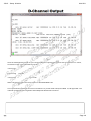
Page 1
CS1K - Setup & Admin
08092801
Index
@
1.
CS 1000 Architecture
4
2.
CS 1000 Components
9
3.
Hardware Installation
24
4.
Software Installation Call Server
32
5.
Software Installation Sig Server
38
6.
Media Gateway Configuration
50
7.
Follower SigServer & Campus Redundancy
64
8.
Maintenance & Admin
71
9.
Virtual Trunks & NRS
93
10. PRI Trunks
113
11. Appendix
122
Page 2
CS1K - Setup & Admin
08092801
Nortel produces a very comprehensive range of documentation for all of their systems.
Previously they supplied an application known as Helmsman which was used to seacrh the archive of
documentation for the relevant information. However wit hthe advent of CS1K Release 5, the Helmsman
application was discontinued and NTP’s (Nortel Technical Publications) are delivered with an Adobe Acrobat
Index file which is used as the search tool.
By opening the .PDX Index file you will be offered the search dialogue seen above. By selecting the option to
search in the Index file, all documents will be referenced and all occurrences returned.
@
Page 3
CS1K - Setup & Admin
08092801
The CS1000 Architecture is as shown above. The ELAN is a private management network whilst the TLAN is
connected to the “Public” side. Telephones maybe connected to the TLAN directly or to a network routed from
the TLAN (Sometimes referred to as the CLAN Customer LAN).
IP Sets sit on the TLAN or a network attached to the TLAN. They need to communicate with the Call Server to
make and receive calls and this is done by registering with the Signalling server. The Signalling server runs
several pieces of software but the sets use the TPS, Telephone Proxy Server to register with and to
communicate with the call server.
When a set registers TPS records its Virtual TN and IP address so it can identify it. In the call server the set is
defined using the Virtual TN.
The Media Gateway is used to provide card slots for Digital & Analogue cards and any others required. It also
provides other services but importantly the IP/TDM conversion via “Media Cards”. This the Media Gateway is
the path to traditional TDM phone sets and the PSTN.
When an IP set makes a call it messages the Call Server via the TPS on the Sig server. The Call server locates
the endpoint for the call and manages the connection. If it is from one IP set to another the call server will signal
the destination via the TPS. When the call is established the voice travels directly form IP Set to IP Set and NOT
via the sig server or call server.
If the end point is a TDM set the call server messages the Media Gateway to allocate TDM/IP resource as well
as signalling the traditional set. The Voice path for the completed call would be via a Media Card.
@
Page 4
CS1K - Setup & Admin
09101511
If the end point is a TDM set the call server messages the Media Gateway to allocate TDM/IP resource as well as signalling the traditional
set. The Voice path for the completed call would be via a Media Card as shown.
IP
IP
IP Set to TPS with Dialled no.
TPS passes to Call Server
Call Server looks up Dialled No.
Call Server returns VTN to TPS
TPS signals Destination IP set
Codecs agreed
Zone Bandwi dth Allocated
Destination picks up
Voice path established directly IP-IP
IP
TDM
IP Set to TPS with Dialled no.
TPS passes to Call Server
Call Server looks up Dialled No.
Call Server contacts Media Gateway with TN of set
Media Gateway signals destination & allocates DSP (Media Card) resource
Codecs agreed
Zone Bandwi dth Allocated
Destination picks up
Voice path established directly IP-DSP
DSP-TDM resource
@@
Page 5
CS1K - Setup & Admin
08092801
Call Server processes all calls and generates CDR etc. All configuration of the system is done on the call server
as it contains the customer database. However the voice path for IP calls does not actually connect to the call
server and ideally it takes the shortest path possible between endpoints.
The Signalling server provides the various signal paths for call setup as well as some other applications.
TPS
Provides a path for UNISTIM messages from the IP sets to the call server. It also tracks the
IP Set VTN against its current IP address.
Element Mgr
Provides a GUI to manage the callserver. Most commands can be executed through the
Element manager interface and the Sig server creates the pages by interrogating the
callserver.
H323/SIP G/W Is the signalling gateway for Virtual Trunk calls between systems. It takes requests from the
callserver across the ELAN, encodes them in either one of the two standard protocols and
then transmits them to the destination endpoint.
NRS
Is the resolver of DN to IP addresses for H323/SIP & UNISTIM
Personal Dir
A directory of up to 100 names specific to any IP set User.
The Media Gateway contains the card space for Analogue and Digital set cards and also provides for the
conversion from IP (Packet Voice) to TDM (Traditional Time Division Multiplexing Voice). In this way IP sets can
work in with both environments.
@
Page 6
CS1K - Setup & Admin
08092801
In a Networked environment with IP Virtual trunks all systems TLAN’s are connected together either over the
WAN or the LAN.
If a call is made from an IP set on the Left hand system to another IP set on the right hand system then the call
server uses the Signalling gateway on the Signalling server (Either H323 or SIP) to set up the trunk. The
Gateway needs to establish where the destination endpoint is and to do this it requests resolution from the NRS.
When it is aware of the destination endpoint it signals directly to it (Signalling gateway to signalling gateway) to
set the call up. The destination signalling gateway will pass the inbound request to its call server and try to
complete the call.
Assuming all is correct, the call will be set up from IP Set to IP set even though the inter system signalling has
passed via the signalling servers.
@
Page 7
CS1K - Setup & Admin
@
08092801
Page 8
CS1K - Setup & Admin
08092801
Pentium IV call servers are only supplied as a redundant pair in discrete chassis.
Currently they can support up to 50 Media Gateways or 22500 IP sets or a combination of the two. Pentium
processors still use the Utility card to house the security dongle and to set the “side” of the switch. Each CPU
will either be 0 or 1 and this is set on DIP switches on the utility card.
Pentium IV systems have a 1Gb Fixed Media device on the board instead of a hard drive and use a 512 Mb
compact flash (Removable Media Device – RMD) for software installation.
@
Page 9
CS1K - Setup & Admin
08092801
CPPM call servers are a single board solution and can be used for Standard availability (SA) & High availability
(HA) systems. The security device is carried on the board itself and the “Side “ information is set in the software.
As a call sever the CPPM has a 1GB Compact flash as its FMD (fixed Media Device – hard drive) and uses a
512 Mb compact flash for software installation, RMD (Removable Media Device). To set the board to boot from
the compact flash the onboard switch is set to position 1.
CPPM devices use a standard IPE slot in a Media Gateway but only receive power from it and connect to the
console port through it. They do not communicate with other cards in the chassis or cabinet across the
backplane.
A High Availability CPPM based system will support a combination of up to 50 Media gateways or 22500 IP
Sets.
@
Page 10
CS1K - Setup & Admin
08092801
HP & IBM servers are known as COTS (Commercial of the Shelf ) servers. They come with 2 Gb or memory
and one hard drive. They have 2 Ethernet ports for ELAN & TLAN and can run either Linux or VXWorks.
The CPPM Sig server is the same board as the call server but it is now equipped with a 40Gb laptop hard drive
instead of the 1Gb compact flash and the onboard switch is set to position 2 to ensure it boots from the hard
disk.
CPPM devices use a standard IPE slot in a Media Gateway but only receive power from it and connect to the
console port through it. They do not communicate with other cards in the chassis or cabinet across the
backplane. If you are using a CPPM sig server in a 1000M it must be the dual width device to avoid fouling other
cards.
Single width CPPM for use in Media gateways
NTDW61
Dual width CPPM for use in CS1000M
NTDW66
The ISP1100 is supported for upgrades but must have a memory upgrade to 1Gb to be used with release 5 or
5.5.
@
Page 11
CS1K - Setup & Admin
08092801
Either the Chassis or Cabinet can be used for the Media gateway on a CS1000E system. The Chassis is a 5 slot
main unit with an optional 4 slot Expander cabinet. The two are connected using 2 copper cables. The expander
is a part of the main media gateway and only adds the 4 card slots , no other functionality.
Each Chassis or Cabinet uses a Media Gateway Controller card to control the cards in the gateway and to
communicate across the ELAN to the Call server.
@
Page 12
CS1K - Setup & Admin
08092801
Always sits in slot 0 in Media Gateway and Is keyed so it wont fit in any other slot.
Provides support for PRI cards in Media gateways
Use a Gold Image to boot from and connect to the call server, this means no software has to be loaded to the
card. Updates are downloaded and stored on the 128Mb Compact flash card on the board.
Has 3 SDI ports on the board which are presented on the triple cable from the normal Serial port on the cabinet
or chassis. The first port is used to configure the card initially but after that they can be configured as extra TTY
ports for the call server.
The MGC has space for 2 DSP daughter boards which come as either 32port or 96 port boards. The maximum
configuration is 1 x 96 port in card position 1 and 1 x 32 port in card position 2 making a total of 128 DSP ports
(TDM/IP ports).
32 port card NTDW62xx
96 port card NTDW64xx
Has the ability to multihome the ELAN & TLAN ports to increas redundancy for Call servers or Sig servers
connected to the passthrough ports CT & CE on the front panel.
The 4 digit display on the front of the card displays the LOOP & SHELF when it is connected to a call server. At
boot up it reports its self test BOOT, POST (Power on self test), PASS (Pass self test), LOAD (Application
Loading). In the event of an error it will display Exxx where xxx is the error number.
@
Page 13
CS1K - Setup & Admin
08092801
The Media Card 32 S provides TDM to IP conversion as did its predecessor the VGMC (Voice Gateway Media
Card) . However it has the additional functionality to encrypt the voice media using Secure Real Time Protocol
(SRTP).
This card can be used where there is no opportunity to use the DSP daughter boards of a MGC ( Upgraded
Media Gateway still retaining the SSC controller) , or in a CS1000M configuration where there are no Media
Gateways at all.
The MC32S does support TPS and will allow set registration as a fallback if all other signalling server members
of its IP telephony node are down. It will support 4 x the no. of ports i.e. 4 x 32 =128 sets.
It is configured as a part of the IP telephony node as it is running TPS.
The ELAN & TLAN connections for the card are achieved using a specialised adaptor which plugs into the 25
pair connector for the card. The Ethernet port on the faceplate is currently unused.
@
Page 14
CS1K - Setup & Admin
@
08092801
Page 15
CS1K - Setup & Admin
08092801
The call server is configured through both the command line interface (CLI) as well as the Element Manager
(EM).
The command line is based on “Overlays” and to interact with the system you need to be in the correct “Load”
(LD) or “Overlay”.
To login you need to type “LOGI” (Not case sensitive) at the prompt, and either add the username you wish to
use on the same line or hit enter and it will prompt you for a USERID.. The system will then request a password.
When you have gained access to the CLI you can change “Overlays” by typing LD and the number of the
overlay you wish to use. The system requires you to exit an overlay before you can enter another and this is
done by typing ****.
@
Page 16
CS1K - Setup & Admin
08092801
When the call server is used as part of a CS1000 system we need to turn on the MULTI User functionality which
is done in LD 17. However only one user can execute a command in the overlays at any one time, if two users
try to access overlays at the same time an OVERLAY CONFLICT message will be generated. This applies to
Element Manage and CLI Users also. Users do not need to log out but do need to exit to Overlay 0 (****) to
avoid this problem .
Multi user allows a user to login more than once and also allows us to look up error messages in the CLI without
exiting the current Overlay. This is done as shown above by typing :
!err “The Error Code to look up”.
@
Page 17
CS1K - Setup & Admin
09101511
The overlay structure is organised as shown into three primary areas.
System
Which deals with the Configuration records, such things as Superloops.
Customer
Most systems only have one customer but there can be several. This deals with the setup of specifics for a
particular customer e.g. Routes and Trunks and CPND information.
Terminal or Set
Relates to the actual set properties. Whilst it shows LD 10 & 11 which still exist it is wise to remember that LD
20 is now a linked overlay allowing operations to be carried out for LD 10, LD 11 & LD 32.
@@
Page 18
CS1K - Setup & Admin
09101511
The debate rages as to which interface, the CLI or the Element Manager is the easiest to use for configuring and
administering the CS1000. In truth it is probably down to how long you have used the system, and the CLI does
have a speed advantage if you know exactly what you want to do.
However one are that the Element manager probably wins on is reviewing configuration information as it is
presented in web page format with some explanation.
If you want to review configuration information through the CLI then the slide here is a useful one to remember
as it points you to the relevant overlay for printing data.
@@
Page 19
CS1K - Setup & Admin
08092801
Element manager (EM) is the standard option with CS1000 to manage the system in conjunction with the CLI. It
can allow you to access 80%-90% of the system through its GUI however some commands are not available
most notably the ability to create and edit Sets.
Some users who have used the CLI in the past find EM a slower way of navigating the system but it does have
some advantages when you are reviewing setup information.
@
Page 20
CS1K - Setup & Admin
08092801
With the advent of Release 5 Nortel launched 2 new servers which run on the new COTS platforms under Linux.
These are the Enterprise Common Manager (ECM) and the SIP Proxy Server or NRSm.
ECM offers a centralised resource for managing multiple systems in a network with the advantage of a single
point of logon and authentication. Because of this the ECM also hosts a Security Server to ensure all
connections between devices are secure and protected by certificates etc. In addition the ECM adds Phone
configuration to the Element Manager functionality ( see above) thus allowing for editing and creation of sets
through the GUI.
The SIP Proxy server is a backup security server and the two are usually deployed together. Its function is to act
as a SIP Proxy for the network channelling all SIP requests and responses through one device and thus
protecting the network. In addition it needs to manipulate the contents of SIP signalling messages to ensure the
IP addresses embedded within them are correct and will make sense at the destination. This usually means
substituting internal addresses for the external IP address of the SIP Proxy for outbound messages and vice
versa for inbound.
NB Note that Linux based servers do not run TPS so do not register IP sets.
@
Page 21
CS1K - Setup & Admin
08092801
The internal addressing of the system is done using Terminal Numbers.
These are defined by the number of LOOPs a system has. On all new CS1000E systems this will be 256,
however on CS1000M systems this may be smaller.
TN’s are used to address cards & units on the cards. A normal TN can be traced to a physical port on the
system itself.
Virtual TN’s on the other hand are used to address devices where there is no discrete physical connection port
such as IP telephones and Virtual Trunks. This does mean that some correlation needs to be made between the
Virtual TN of an IP Set and its IP address. This is done by the Terminal Proxy Server on the Signalling server at
set registration time.
@
Page 22
CS1K - Setup & Admin
@
08092801
Page 23
CS1K - Setup & Admin
08092801
The CS1000E is either Chassis or Cabinet based . The Chassis systems are all rack mounted and depending
on the Sig Servers used may or may not have other rack mounted items to complete them. Notably all systems
will need IP switches, either Layer 2 or Layer 3 and these will end to be rack mount items.
Cabinet based systems are wall mounted but again if ISP 1100 or COTS servers are used as sig servers they
will have a requirement for standard racks. A system can mix both Cabinet and Chassis based media gateways.
CS1000M Single or Multi Group systems will use their own chassis as normal and the only requirement then is
to house sig servers . If CPPM servers are used then the need for racks is reduces to any ethernet switching
required.
@
Page 24
CS1K - Setup & Admin
08092801
Grounding is important for chassis based media gateways and each has a grounding post (Main & Expander for
this purpose. Check the NTP’s for your country requirements.
Sig Servers ( Non CPPM ) and the Pentuim IV chassis is sufficiently grounded by the AC connection outlet.
@
Page 25
CS1K - Setup & Admin
08092801
If using the Media Gateway chassis then the above shows the relevant ports for connection. The cards in the
units will use the 25 Pair connectors to link to the MDF. In a chassis configuration the Main unit & Expander are
linked by 2 copper cables.
MGC SDI (Serial Data Interface) ports are connected using the “Triple Cable” these ports are used for the initial
configuration of the MGC card itself but once it has been integrated and has registered with the call server they
can be configured as further TTY ports on the call server itself for access or CDR collection etc.
The ELAN & TLAN ports on the back of the chassis are the redundant connections for the MGC and mirror the
1E & 2T ports on the faceplate of the card itself. If you are not using multihoming then either connection maybe
used. Swapping between these ports is controlled by the MGC itself and is not reliant upon any other network
interaction.
@
Page 26
CS1K - Setup & Admin
08092801
The Bulkhead ports on the Media Gateway are used purely for connecting to the back of the chassis. They act
like an extension cable only and can be used by any connection ELAN or TLAN on the system.
The DIP switches are used to set the ring frequency etc and should be set according to the relevant NTP.
@
Page 27
CS1K - Setup & Admin
08092801
The Media Gateway cabinet is similar in requirements to the chassis as far a card connections go but he
location of connectors is at the bottom of the cabinet.
The SDI ports are connected again using the triple cable and the ELAN & TLAN redundant ports are connected
using a specialised adaptor similar but not the same as the Media card adaptor. This allows for the duplication of
the 1E & 2T ports on the faceplate of the MGC itself in slot 0.
@
Page 28
CS1K - Setup & Admin
08092801
A special cable is required to connect to the 2 SDI ports on any CPPM board. This uses the 25 pair card
connector and delivers 2 25 pin “D type” serial ports for connection to a terminal .
This is the same for both CPPM call servers and sig servers. The default baud rate is 9600 for these boards.
@
Page 29
CS1K - Setup & Admin
08092801
The LAN connections for the system are important and in order to maximise the redundancy of the switch you
can take advantage of the multi homing aspects of the MGC cards.
The diagram above shows 3 media gateways schematically and their MGC cards. These are connected to
redundant ELAN & TLAN Ethernet switches via the front faceplate and “rear” redundant ports. This allows the
MGC to continue to function even if one of the ELAN or TLAN switches fails.
NB Note that the interconnection between the Ethernet switches has been omitted for clarity.
To fully utilise this redundancy the Call Server ELAN connections have been connected to the network using
the pass through ports ( CE ) on the front of the MGC. Similarly the Sig Server has both ELAN & TLAN
connections to CE & CT on the front of its MGC card.
@
Page 30
CS1K - Setup & Admin
@
08092801
Page 31
CS1K - Setup & Admin
08092801
To Install the software the Server is reset and booted from the installation device by pressing “F” for the
faceplate Compact flash on both the CPPM and Pentium IV processors. If you are upgrading an existing
Pentium II then you will still have to press F but this is to boot from the floppy drive where the installer disk is
located. You will also need the CD with the software on it and a keycode diskette.
If the server is a CPPM and has been installed previously it may require a second “F” at a second prompt to
avoid it booting from the hard drive.
Once the installer menu is displayed hit the return key and you will be asked a couple of questions to which you
reply “y”.
This will bring you to the main menu where you will type a “u” to proceed to the install menu. You will then be
asked to select the keycode you wish to install. Usually you will only have one. The system will check you are
happy with the keycode before proceeding.
@
Page 32
CS1K - Setup & Admin
08092801
Once you have confirmed the keycode the installer will ask you what you want to install. This is usually option
“b” , the software BootROM and a customer database.
On the CPPM call server it will then ask about the “Side” information, this is the CPU designation for a Dual
CPU system. If you have a Dual CPU system (HA) then one processor must be set to 0 and the other set to 1 so
they can work together correctly. If you only have a Standard Availability (SA) system with one CPU then it is
always side 0.
Also on the CPPM card it will ask where the board is situated. IE in which Media Gateway it is housed. Thus you
will need to give it the Loop and Shelf number. This information is purely for inventory purposes and can be
reset later in LD 117 should you get it wrong. It will not affect the system performance should you report it
incorrectly.
If you are installing a Pentium system you will not be prompted for this information as the Side is set using DIP
switches on the utility board..
Other questions will be asked about adding Dependency lists and Centralised software upgrade which you
should take the default choices for. When the install is complete select the option to quit and reboot. If the
system you are building is a dual processor you repeat the install on the other core at this point.
@
Page 33
CS1K - Setup & Admin
08092801
The call server needs to be prepared to communicate with the signalling server and thus provide our IP
telephony environment. The first thing required is an IP address on the ELAN connection and if required a
default Route.
You will need to create at least two Pseudo TTY (Teletype) Ports. TTY ports are how the system addresses the
Serial Data Interface ports. When we connect using the Network rather than a serial connection we need PTY’s
to define these paths into the system. PTY’s are used by the Element Manager, Virtual Terminals & Telephony
Manager. We also turn on Multi User Support for the call server to enable multiple logins.
Finally we need to create a Customer Data Block which is like a main index for services on the system. It is
possible to share the CS1000 between various customers each having different functionality.
LD 17
REQ
TY PE
ADAN
To add 2 PTY’s
chg
adan
new tty 10 & 11
CTY P
PORT
pty
<cr>
MULTI_USER
on
DES
comment
LD 15
Add a Customer Data Block
FLOW
USER
TTY LOG
BANR
<cr>
mtc sch bug
<cr>
<cr>
REQ
new
LD 17
Turn on Multi User
REQ
chg
TY PE
ovly
.
@
TY PE
cdb
CUST
0
<cr> to the end
Page 34
CS1K - Setup & Admin
08092801
When installing a new system you should check the Call Register and 500B settings as outlined in the NTP.
These could need updating if you are converting from an old system.
@
Page 35
CS1K - Setup & Admin
08092801
The Call Server will need to have an IP address if it is to be the centre of a VoIP system.This address will be an
ELAN address and is set on the call server in load 117. Dependent on the configuration either one or two
addresses may be required. If the system is Standard availability then only one address is needed but if it is
High Availability ( Dual CPU ) then an address will be required for each of the processors.
The process is to assign an IP address to a Hostname using the
NEW HOST “Hostname” “IP Address”
command. The Subnet Mask can be set using the command
CHG MASK “Subnet Mask”
Once this is done the Address is brought into service by command
CHG ELNK ACTIVE (or INACTIVE) “Hostname”
A Default Route is added using the commands
=>NEW ROUTE 0.0.0.0 “IP Addr of Router”
=>PRT ROUTE
=>ENL ROUTE “Route ID from list”
In LD 137 there are commands to enable & Disable the ELAN as well as seeing its status
ENL ELNK / DIS ELNK / STAT ELNK
@
Page 36
CS1K - Setup & Admin
@
08092801
Page 37
CS1K - Setup & Admin
08092801
Once the Call Server is up & Running and the basic configuration has been done then its time to add the Leader
signalling server.
The Server is reset and booted from the installation device by either pressing “F” for the faceplate Compact
flash on the CPPM Sig Server or C for CD-ROM on the 1U IBM or HP Servers ( or existing ISP1100).
If the server has been installed previously it may require a second “F” at a second prompt to avoid it booting
from the hard drive.
When the installation screen is seen respond to the prompts till you reach the main installation menu. Generally
you will use option “a” to do a full software install including Firmware and Loadware.
However if you are only changing the server configuration and don’t need to install the software you can choose
option “e”.
Before the installation starts you will be asked further questions. If this is a CPPM sig server you will be asked
for the Location of the card I.E. the Loop and Shelf numbers. In addition you will be asked if you want to add any
Dependency Lists on the installer. You should reply “Y” yes to this to ensure you have the latest updates.
Selecting “t” for the Tools Menu will give you some other useful options discussed later.
@
Page 38
CS1K - Setup & Admin
08092801
Once the software has been loaded the installer will ask you for a copy of the configuration . If you are replacing
a sig server check to see if a copy was made when the first installation was done.
If this is the first installation or you don’t have a copy of the configuration choose option “b” to continue without
restoring and the installer will proceed to set the configuration up manually.
Every system needs a Leader sig server so if this is the only or first server it should be a Leader. The installer
will then ask about the applications to be run ( TPS, Virtual Trunks and NRS ) and the protocol for the virtual
trunks and the NRS role.
@
Page 39
CS1K - Setup & Admin
@
08092801
Page 40
CS1K - Setup & Admin
08092801
The information the installer will ask for is shown above.
The IP addresses for the ELAN & TLAN are straightforward as is a Hostname which just identifies the sig
server. Also the Call server ELAN address will be needed for communications between the devices.
The NRS role is either Primary, Alternate or Failsafe and will be discussed more later on. The Primary and
Alternate IP addresses are the TLAN IP addresses of the relevant Sig servers.
The IP Telephony node is discussed on the next page.
@
Page 41
CS1K - Setup & Admin
08092801
The Node IP address is held by the Leader of the IP telephony node. This will normally be a signalling server.
However in the event that there are no signalling servers running a Media Card maybe elected leader. In this
instance the Media Card will also register IP sets. The capacity of the card is four times the number of ports on
the Media card. Thus for a 32 port SMC card this is 128
Sets can not be prioritised for registration to the media card. It is done on a first come first served basis.
The IP sets are configured with the IP Node address, thus even in the event of a Sig server failure the IP Node
address will still be available via the Node leader even if that should be a Media card.
All of the devices running TPS ( Sig servers, MC32S, VGMC ) are included in the IP Telephony node. A system
can have multiple IP nodes. The Node ID is a number to identify the node and can be up to 4 digits. The Node
IP address is a TLAN address but is different to the TLAN address of the sig server itsellf.
@
Page 42
CS1K - Setup & Admin
08092801
Once you have added all the required information the installer will ask you to verify it and give you the option to
change it before continuing.
Once complete you can quit the installer and let the sig server reboot.
@
Page 43
CS1K - Setup & Admin
08092801
The Element Manager is accessed from Internet Explorer by entering one of the IP addresses of the signalling
server, ELAN, TLAN or NODE IP (This is dependent on the network you are attached to and how it is
connected) .
On a new system the first thing to do is to import the IP Telephony Node information from the Leader Sig server.
@
Page 44
CS1K - Setup & Admin
08092801
To import the node go to IP Network / Nodes, Servers, Media Cards .
If there is no node already the system will prompt you and offer import the node. This is done using the dialogue
above and entering the ELAN IP address of the Leader sig server. This will copy the files from the Leader Sig
server to the FMD of the call server. Because the node files are held on the call server they are backed up with
he rest of the system during a normal system backup (LD 43 EDD).
@
Page 45
CS1K - Setup & Admin
08092801
Once the Node is imported it will be displayed and can be edited using the EDIT button.
When the edits are completed the information is stored to the call server hard drive by using the SAVE &
TRANSFER button. In addition the information is transferred out to all devices making up the IP Node i.e.
Signalling servers and Media cards.
@
Page 46
CS1K - Setup & Admin
08092801
One of the things contained in the IP Telephony Node is the codec selection.
The default codecs used are G711 and T38 (Fax), these cannot be deselected. However you can add other
codec support such as G729 and also you can edit the payload size used by the system. This will change the
amount of bandwidth required for each call.
When a change has been made here you must Save & Transfer to store it.
@
Page 47
CS1K - Setup & Admin
08092801
Right at the bottom of the IP Telephony node you will find a Signalling Server tab which when expanded will
show the information entered during the installation.
You may wish to turn off the IP PEER GATEWAY functionality at this point until we are ready to configure it.
Note also the MAC address of the leader sig server has been inserted automatically.
@
Page 48
CS1K - Setup & Admin
@
08092801
Page 49
CS1K - Setup & Admin
08092801
Zones are an artificial mechanism to control the number of calls made on a VoIP network. The concept is often
referred to as Call Admission Control or CAC. CAC is necessary to prevent too many calls affecting call quality.
In a TDM network this cannot occur as each call has its own dedicated circuit but in packet telephony we are
sharing bandwidth and hence issues can occur.
If the 2 phones in zone A call each other thy have plenty of Intra zone bandwidth so the call can proceed. The
system will deduct an amount of bandwidth equivalent to the calls usage from the Zone whilst the call is in place,
and add it back when the call clears. Thus if there is insufficient bandwidth to allow the call it will be refused
protecting the quality of other calls.
In the diagram the 2 zones have a low speed link between them of 512K. IntraZone calls will be fine but
InterZone calls to Zone 1 will be more restricted.
The Strategy for calls allows us to choose a suitable codec depending on the call type. In the diagram we have
selected BQ (Best Quality) for Intra Zone calls which will result in the G711 codec being used and consequently
more bandwidth. However for InterZone calls we have selected BB (Best Bandwidth) which means a higher
compression codec using less bandwidth will be selected if available. This will usually be G.729 and VAD (Voice
activity Detection ) may also be selected to save even more bandwidth allowing more calls to use the link at the
same time.
@
Page 50
CS1K - Setup & Admin
08092801
Zone creation and selection through the Element Manager.
There are three types of Zone, the MO Main office zone for most applications, the VTRK, Virtual Trunk zone for
Virtual Trunks and the BMG, Branch Media Gateway zone for Branch office networks.
There is also the option to make a zone private or shared, Private zones do not allow Media card resources to
be shared to another zone, this can be useful in certain configurations e.g. Inbound call centres where you need
to keep all IP/TDM resources available.
Zones can also be configured and printed in LD 117.
@
Page 51
CS1K - Setup & Admin
08092801
To add the Media Gateway select the link IP NETWORK / MEDIA GATEWAYS.
Using the ADD button select the Superloop and shelf for the MG to be allocated to. Remember that 1 superloop
supports 2 Media Gateways, one on shelf 0 and the other on shelf 1. You will need to enter the ELAN IP
address of the MGC card controlling the Media Gateway.
When you submit this you will be asked if you want to add the full media gateway configuration. This will open
the second dialogue where you can add all of the IP addresses for the MGC card and the daughter boards
installed on it. Submit the information – do not click on VGW CHANELS at this point.
Once the MG is created you will need to add TDS & Conference loops to it
Select the MG to add loops to and use the DIGITAL TRUNKING button to move to the correct dialogue. You will
then have the option to add 2 x TDS loop and 2 x Conference loop.
@
Page 52
CS1K - Setup & Admin
08092801
Every Media Gateway requires Tone and conference resource. These functions are handled by the MGC card
but must be addressed by the system using a Loop number. Hence when you configure them you must allocate
a single loop to each resource. There is no set strategy to which Loop number is used but you need to choose a
suitable number that will not interfere with other system components. A suitable option would be Loop 120.
Each Media Gateway supports up to two MGTDS & MGCONF Loops. Each Conference resource supports 30
conference circuits allowing up to 60 circuits in total per media gateway.
Select the MG to add loops to and use the DIGITAL TRUNKING button to move to the correct dialogue. You will
then have the option to add 2 x TDS loop and 2 x Conference loop.
Conference and TDS loops can also be added through LD17.
@
Page 53
CS1K - Setup & Admin
08092801
Once the Media Gateway is configured into the Element Manager you need to configure the actual MGC with IP
addresses so it can communicate with the call server and the rest of the system.
To do this on a new card or one that has been cleared you simply need to power it on with a terminal connected
to the Console port 0 of the card. If there are no IP addresses configured the card will automatically run
“mgcsetup” which will prompt you for the relevant information.
The advanced parameters are used to configure the ELAN & TLAN ports and to select ELAN security. Intra
System Signalling Security is based on the IPsec protocol and is used on the ELAN to protect the signalling
between different devices. Ensure you build your system and ensure it is working correctly before attempting to
use ISSS.
@
Page 54
CS1K - Setup & Admin
08092801
In the Element Manager Superloops can be listed and also created . Above you can see the IPMG Superloop
used to define the Media Gateways and the Virtual Superloop which is used for the IP sets and Virtual Trunks.
@
Page 55
CS1K - Setup & Admin
08092801
A Virtual Superloop can also be configured using LD97
>chg
TYPE supl
SUPL V252
This will create superloop 252 as a Virtual superloop which can be used for IP sets or Virtual trunks.
@
Page 56
CS1K - Setup & Admin
Phone Sets can be configured in LD 10 (Analogue),
LD 11 (Digital & IP) or LD 20 (Either). Below is a
configuration for an analogue ( 500 ) set, the FALC
(Flexible Analogue Card ) is located in Media
Gateway 0 0 card slot 2
08092801
AST
IAPG
HUNT
TGAR 0
LDN
REQ NEW
TYPE:
TYPE 500
Analogue set on FALC
TN 0 0 2 1
CDEN
DES 500
CUST 0
ERL
WRLS NO
DN 1200
MIX
MARP ON TN 000 0 02 00
MARP
CPND
VMB
@
NCOS
RNPG
SGRP
SFLT
CAC_MFC
CLS
SCI
MLWU_LANG
PLEV
FTR
MIX
MGMT001 TNB NEW TYPE:500 TN:0 0 2 1
Page 57
CS1K - Setup & Admin
08092801
IP sets need configuration so they will register to the correct call server. This can be done using the DHCP
server and sending a full string of configuration parameters to the set. It can also be done manually by
accessing the configuration menu.
On the 1100 series phones this can be done by pressing twice on the services key which will present a further
menu. Select Network configuration from this menu and use the navigation keys to select the parameters to
change using the central select key.
On the 200X sets press the 4 keys below the display when the set restarts and “NORTEL” is displayed. This will
then allow you to step through the configuration parameters.
To reset a phone either power it down and back up or use the following key sequence:MUTE UP DOWN UP DOWN UP MUTE 9 RELEASE.
@
S1
Points to the Node IP Address of the system
S1 Port
4100
S1 Action
1
S1 Retry Count
Number of times to try registering
Page 58
CS1K - Setup & Admin
08092801
The diagram above shows how the cards in the Media Gateway are arranged and addressed by the system.
As well as the eight physical card slots there are “Virtual” cards as shown (slot 0 and Slots 11-15). These are
used to address the DSP daughterboard cards and also the Digitone Receivers required on the Media Gateway.
DSP Daughter Board 1
Cards 11,12 & 13
DSP Daughter Board 2
Card 0
Digitone Receivers
Cards 14 & 15 ( 8 per card units 0-7)
Digitone receivers are required to interpret the DTMF dialling from analogue sets registered to the Media
Gateway. The functionality is hosted on the MGC on the virtual cards as described above. The DTR’s can be
configured through the Element Manager or via LD 13.
@
Page 59
CS1K - Setup & Admin
08092801
A PAD table is required before you can add the VGW Channels.
PAD Tables provide gain or attenuation values to condition the level of the digitised transmission signal
according to the network loss plan. The PAD table should be configured with the country specific values as
defined in the NTP’s. (See Appendix)
First create the DDB using the default values (EM or LD 73) . This will create a pad table 15 which can be edited
to the correct values.
@
Page 60
CS1K - Setup & Admin
08092801
VGW channels can be added from the Media Gateway screen or through the overlays (LD14). These are the
actual channels that will be used to convert the IP calls to TDM and vice versa.
NOTE:
If you are using Media Gateway 0 0 then the DSP Daughter board in position 2 of the MGC will
have as its first TN 0 0 0 0. As this is a reserved TN you have to configure from TN 0 0 0 1 and lose one
channel.
@
Page 61
CS1K - Setup & Admin
@
08092801
Page 62
CS1K - Setup & Admin
@
08092801
Page 63
CS1K - Setup & Admin
08092801
Signalling servers have a limit for IP Set registrations of 5000 units and therefore to support more than this a
system will require multiple devices. In addition a system may have redundant servers to allow for failures.
The follower sig server uses the BOOTP protocol to collect its IP information from the Leader sig server. After it
has established its identity it works as a normal server and sets will load balance across all available units.
In the event of a failure of the Leader sig server a follower will be “Elected” as the new leader and it will assume
the Node IP address as well.
@
Page 64
CS1K - Setup & Admin
08092801
First of all edit the IP Telephony Node as shown above. Scroll down to the Signalling Server section
Use the ADD button to create a new Signalling Server. As you can see it has only zero’s initially so you must
add the IP addresses for the server as required. In addition you will need the MAC address of the ELAN port.
Follower Signalling Servers Use BOOTP to obtain their IP configuration from the Leader signalling by sending
out a request at Boot time. Thus the MAC address is required to identify the Follower server.
Once the configuration is added carry out a save and transfer to ensure the information is on the leader
signalling server. The Save and Transfer will fail to the Follower Signalling server as it will not yet be loaded with
software and running.
Then move to the Server itself to configure the installed software.
@
Page 65
CS1K - Setup & Admin
08092801
Once the configuration has been added to the Element Manager you can install the software to the server itself.
This is the same basic process as the Leader signalling server.
Once the software has loaded and the system prompts you for the configuration enter <b> as shown above for a
Follower.
As the Follower will be using BOOTP as stated before you will only need to enter the Hostname of the Leader
signalling server for identification purposes. The list on the right will be shown with only the Hostname entry. If it
is correct enter <Y> to accept it then select options to quit the installation menus and reboot the server.
As the server boots this time it should request and receive its IP configuration from the Leader signalling server.
If you observe the command line of the server as it boots you will see a series of plus signs( +++ ) as it tries to
obtain its information. If it is successful it will continue to boot and you can then return to the Element Manager
screen and transfer the IP Node information to it.
You will probably have to reset the Follower after this to ensure that the TPS is correctly initialised.
@
Page 66
CS1K - Setup & Admin
@
08092801
Page 67
CS1K - Setup & Admin
08092801
By using multiple Ethernet switches configured with VLAN’s for ELAN TLAN and the High Speed Pipe (HSP) the
Campus Redundant system can offer a very high level of availability from a Dual CPU system.
Campus redundancy is only applicable to the CS1000E system not 1000M systems. Also it should be
remembered that Campus Redundancy is a single Dual Proccessor system unlike Branch Office or Geographic
Redundancy which require two or more systems.
@
Page 68
CS1K - Setup & Admin
08092801
Campus Redundancy is a single High Availability system where the two call servers have been placed at some
distance from each other. This can be as much as 40Km using Fibre connected switches.
High Availability/Campus Redundancy allows for both Fault Tolerance as well as planned maintenance and
upgrades.
@
Page 69
CS1K - Setup & Admin
@
08092801
Page 70
CS1K - Setup & Admin
08092801
New accounts and passwords can be added via the Element Manager or Overlay 17
PWD2 ( Default Account ADMIN2 ) is the user with security access and this is the account to use to create new
users.
In addition you now have the option to add PDT access to an account and this is useful to enable patching to be
carried out.
@
Page 71
CS1K - Setup & Admin
08092801
STAT SERV is a very useful command to show the status of connections to the components of the system. Note
particularly the PBXLINK STATE column.
STAT IPMG will list the configured and registered Media Gateways on the system.
@
Page 72
CS1K - Setup & Admin
09101511
One thing to always try when devices seem to be okay but still function incorrectly is to DISABLE them and then
ENABLE.
Depending on the device you are working on you need to choose the right command as shown here. For a
single phone you can use the unit option DISU command in LD 20 (or LD 32). Be aware that on a set the display
will remain as if the set is working however you wont be able to pick up a line to dial with.
Whilst you can do this with a single digital set it often better to disable the whole card and then re-enable it. This
ensures that it re initialises with the Call Server correctly. Use the DISC for this option.
All cards should be disabled before removal.
Some devices such as PRI , Tone and Conference circuits are addressed as Loops. Thus you use the DISL
command to disable these in specific overlays:PRI – 60 / TDS – 34 / CONF - 38
@@
Page 73
CS1K - Setup & Admin
09101511
Hunt groups use a list in the overlays which needs to be allocated, so if its a new switch you may need to define
the number of lists in LD 17 before you start.
If you have lists allocated already then the next step is to define the Hunt Group in LD 18 as shown.
You will need to know the list number you are going to use, the length of the DN’s included and the number of
entries to be included. Then you simply add the DN entries.
Once the list is created you need to assign it to a DN (PLDN) in the system which of course must be unique.
This is done in LD 57 (FFC)
@@
Page 74
CS1K - Setup & Admin
08092801
Phone Firmware is an important part of the system and needs to be kept current.
This can be done using a terminal linked to both the EM and the Internet. By clicking on the Links ( In Blue ) the
system will automatically try to download the requested file.
The Currency file is a list of the latest firmware available and this should be updated first. From this you can
select which devices need new firmware.
@
Page 75
CS1K - Setup & Admin
08092801
You can see from these slides that both the recommended list and the TPS Firmware for the Node has now
been upgraded.
It is necessary to reset the IP phone to force it to upgrade the firmware it is using. This can be done manually by
restarting the set or remotely by using the isetReset command on the signalling server.
@
Page 76
CS1K - Setup & Admin
08092801
Backups can be carried out through both the overlays and the Element Manager.
In addition there are several backup rules which can be created to backup to a FTP server or the FMD or RMD.
Multiple backups can also be created up to a maximum of 10.
@
Page 77
CS1K - Setup & Admin
08092801
Once you have a backup rule you can create a schedule to execute it at particular times.
@
Page 78
CS1K - Setup & Admin
@
08092801
Page 79
CS1K - Setup & Admin
@
08092801
Page 80
CS1K - Setup & Admin
@
08092801
Page 81
CS1K - Setup & Admin
@
08092801
Page 82
CS1K - Setup & Admin
@
08092801
Page 83
CS1K - Setup & Admin
@
08092801
Page 84
CS1K - Setup & Admin
@
08092801
Page 85
CS1K - Setup & Admin
@
08092801
Page 86
CS1K - Setup & Admin
09101511
On the IP set itself you can perform several simple checks and Diagnostics.
Access the Local Tools menu by a swift double press on the services key (A Globe with two arrows ). From
there select Local Diagnostics which will offer you a selection of information and diagnostics.
In the figure you can see the configuration information displayed as well as a TRACEROUTE from the set itself.
Using PING and TRACEROUTE from the Set can help to resolve issues on the sets especially things like one
way speech.
@@
Page 87
CS1K - Setup & Admin
09101511
The TRAC command in LD 80 can be a very useful tool for investigating problems on the sy stem.
The sy ntax of the command is :TRAC <Customer No.> <DN>
>ld 80
TRA000
.trac 0 1200
ACTIVE TN 000 0 02 00 IPMG 000 0
ORIG VTN 252 0 05 10 KEY 0 SCR
Or
TRAC <TN>
.trac 100 0 0 0
VTN 100 0 00 00
KEY 0 SCR MARP IDLE
KEY 1 SCR MARP IDLE
KEY 2 NUL IDLE
@@
Page 88
CS1K - Setup & Admin
09101511
Monitoring the D-Channel is an extremely helpful tool in understanding what is happening to a routed call.
However you need to be careful using this tool on a busy switch as it can generate a lot of output which could
have an impact on performance.
The STAT MON command in LD 96 shown displays the current monitoring status. Monitoring is a two part
operation as of Release 5:1.
Enable the messages for DCH
2.
Enable the output to either TTY a LOG file or both.
( In Previous Releases there was no option for the Trace Output )
To trace a D-Channel, firstly enable the inbound and/or outbound messages for the channel in question.
>enl msgi <DCH no.>
>enl msgo <DCH no.>
@@
Page 89
CS1K - Setup & Admin
09101511
Once the messages are turned on, you need to enable the output and this can be sent to either the TTY screen,
a LOG file or both. This is also done in LD 96 :>enl mon tty
>enl mon log
>enl mon all
TTY
LOG file
TTY+LOG
When using the log option the file is created in /U/TRACE/DCH.LOG.
The output shows a message sent out on TN 200 0 0 14 ( A SIP virtual Trunk) from DCH 10, call type CDP. The
inbound message shows a regection and subsequent release of the channel.
@@
Page 90
CS1K - Setup & Admin
@
08092801
Page 91
CS1K - Setup & Admin
@
08092801
Page 92
CS1K - Setup & Admin
@
08092801
Page 93
CS1K - Setup & Admin
08092801
Both H.323 and SIP are available on CS1K to create Virtual Trunks.
SIP was introduced at Release 4 but is now the preferred option and more development has been done in
Release 5. Much of this is relates to the integration with Microsoft OCS.
@
Page 94
CS1K - Setup & Admin
CDP
COORDINATED DIAL PLAN
UDP
UNIFORM DIAL PLAN
08092801
SIP is very much Domain based and therefore we need to add this information into the system as well as
aligning the SIP domains to the Dialling plans within the CS1K .
@
Page 95
CS1K - Setup & Admin
09101511
The Routing Process for a dialled number that isn’t a DN on the systems is outlined here. Existing DN’s could be
Extensions, Hunt groups, Phantom numbers etc.
First the system checks whether an Access code (AC1 or AC2 ) has been dialled. If it has, it will firstly remove
the AC code and then restrict its search for a match to the relevant list.
The subsequent match will also attach a Call Type to the call which is carried along with it.
If the first digit dialled is neither of the two AC codes then the system will search through the Steering codes
(Distance, Local & Trunk) for a match again with a call type being added.
The generated match will point to a Route List Index, (RLI) this is a table which directs the call to the right Route
off the system. It will also apply a Digit Manipulation (DMI) before forwarding to the route and finally the trunk.
The DMI will delete and insert digits as required .
@@
Page 96
CS1K - Setup & Admin
08092801
Firstly Enable ISDN ( Package 145 ) for the customer.
@
Page 97
CS1K - Setup & Admin
08092801
We need to create a Virtual D-Channel for the Virtual Trunks. Navigate to the D-Channel screen and select the
DCH number to add.
This D-Channel can be used for all IP Trunks even if you are running both SIP & H.323 Trunks. The Channel ID
number configured on the Trunks themselves will identify exactly which to use.
The D-Channel type will be DCIP ( D-Channel over IP )
Select the USER as ISLD and the interface as SL1 as we will be sending MCDN over the IP Peer trunks.
@
Page 98
CS1K - Setup & Admin
08092801
Once the DCH is created we will need a VTRK Zone before we can create the route.
The Zone is much the same as the Main Office zone created for IP sets but its Zone intent must be set to VTRK
or it will not be accepted when you configure the Route.
@
Page 99
CS1K - Setup & Admin
08092801
Next we create the VTRK route itself and the Trunks .
Note on the Virtual Trunks we must select the Protocol type we are using i.e SIP or H323. We also set the Mode
of Operation (MODE) to ISLD and the Interface type for Route (IFC) to ISLD.
The Virtual Trunks will need Virtual TN’s to configure them so ensure you have created a Virtual SUPERLOOP.
@
Page 100
CS1K - Setup & Admin
08092801
To allow us to programme Steering codes etc we need to create the default ESN tables.
Use the default values for Network Control Basic Parameters.
@
Page 101
CS1K - Setup & Admin
08092801
We need to setup the ESN Access Codes and Parameters, set all values that are “Maximum....” to 100 except
Maximum Number of Common Carriers which should be set to 0.
Set AC1 to 9 and AC2 to 6.
@
Page 102
CS1K - Setup & Admin
08092801
Steering codes are added to point the call to the correct route via the Route List Index.
@
Page 103
CS1K - Setup & Admin
08092801
The Gateway information and Domains for SIP are entered into the IP Telephony Node.
@
Page 104
CS1K - Setup & Admin
08092801
@
Page 105
CS1K - Setup & Admin
08092801
The NRS can be accessed from the Element Manager but it is possibly easier to access it directly by using the
IP address of the server followed by “/nrs” e.g. 192.168.0.1/nrs
The Default login for the NRS is Uname: Admin Pword: Admin.
Once logged in you can add further users.
@
Page 106
CS1K - Setup & Admin
08092801
Check that the System Wide Settings are correct and adjust the DB Sync Interval (Synchronisation of Primary,
Alternate and Failsafe NRS) to a suitable setting.
Also ensure that the NRS Server settings point to the correct Primary and Alternate NRS.
To start configuration of the NRS click on the CONFIGURATION Tab, and then select the “Standby View” as
configuration can only be made in Standby mode.
@
Page 107
CS1K - Setup & Admin
08092801
Once in Standby mode we can start to add the information such as the
�Service or SIP Domain
�L1 Domain (UDP)
�L0 Domain (CDP)
@
Page 108
CS1K - Setup & Admin
08092801
With the Domains in place we can start to add Gateway Endpoints which define each of the systems being
served by the NRS.
Each Endpoint is added into the correct Domain and then configured with the appropriate Protocol Support (SIP
or H323).
The Network Connect Server can also be enabled here, this provides support for UniStim requests specifically
for Network Virtual Office, Branch Office and Geographic Redundancy.
@
Page 109
CS1K - Setup & Admin
08092801
With the Endpoints in Place we can then add Routing entries to specific Endpoints.
Select the ROUTING ENTRIES menu item and select the Endpoint you wish to configure, note the LOOK UP
link (In Blue) will allow you to browse the Endpoints.
Once the Endpoint is selected you can then add the specific Route you require selecting :�DN Type (CDP/UDP/SPN etc)
�DN Prefix (i.e. The starting number pattern to match to)
�Route Cost ( This is used to determine which route to use when there is more than one option )
@
Page 110
CS1K - Setup & Admin
08092801
Finally the configuration data must be moved to the Active side of the database
To do this select the TOOLS tab and DATABASE ACTIONS menu item. There are options to :�CUTOVER
Moves Standby Config to Active for testing can be reversed
�COMMIT
Commits current Active Config changes to Db
�ROLLBACK/REVERT
Goes back to Previous Active Db
�CUTOVER & COMMIT
Moves Standby to Active and Commits in one operation
In the Lab we can use CUTOVER & COMMIT but in the filed you should CUTOVER the Db first. Carry out
testing and then COMMIT when you are satisfied with the changes made. If a CUTOVER is used, no further
changes can be made until a COMMIT is done or the changes are reversed.
@@
Page 111
CS1K - Setup & Admin
08092801
@
Page 112
CS1K - Setup & Admin
08092801
As we’ve already configured the Virtual Trunks ISDN is switched on for the customer so we don’t need to do that
again.
Due to Lab constraints we will be configuring MCDN trunks from one system to another so the setup will be
different to that you would use if you were configuring to a carrier ISDN circuit. (Protocol etc.)
To configure the PRI LOOP number first select the Media Gateway it is installed in and click the DIGITAL
TRUNKING button. Then select PRI” from the ADD drop down menu.
@@
Page 113
CS1K - Setup & Admin
08092801
To configure the PRI LOOP number first select the Media Gateway it is installed in and click the DIGITAL
TRUNKING button. Then select PRI” from the ADD drop down menu.
The system will prompt for a LOOP number to assign to the PRI. This must be an unused LOOP number and is
not part of any existing SUPERLOOP. Here we have selected LOOP 100.
@@
Page 114
CS1K - Setup & Admin
08092801
After selecting the D-Channel number to use we are presented with the standard dialogue screen.
Note that in the D-Channel we are stating which DCH card is being used and as ours are daughter boards on
the PRI itself the location (MG_CARD) is the same as the PRI e.g. 000 0 1 i.e. where the card is located in the
Media Gateway.
As the trunks we are configuring are connecting together CS1K systems we have selected User(USR) as PRI
and the Interface type for D-channel (IFC) as SL1. If you were configuring this to a different type of system or to
the PSTN this would need to be selected appropriately.
Again as we are working “Back to Back” with another system we must define one end as NET as shown here
and the other as USR. In a PSTN scenario the carrier end would always be NET so you would select USR.
@@
Page 115
CS1K - Setup & Admin
08092801
Once the D-Channel is complete we can configure a Route for the PRI.
Note the following basic settings :-
@@
�Trunk Type (TKPT)
TIE
�Incoming and Outgoing (ICOG)
IAO
�Digital Trunk Route(DTRK)
Tick the Box
�Digital Trunk Type (DGTP)
PRI2
�ISDN
Tick the Box
�Mode of Operation (MODE)
PRA
�Interface type for Route (IFC)
SL1
Page 116
CS1K - Setup & Admin
08092801
Once the Route is configured we can add the Trunks to it.
Note that the TN used is the LOOP number assigned to the PRI card and that unit number starts at 1 rather than
0 as it is reserved for syncronisation..
The Route Number, Member Number (RTMB) is as it says “Route Number” “ The first Member Number (1)” and
as we are adding 30 channels in total the system will increment this for us automatically.
@@
Page 117
CS1K - Setup & Admin
08092801
The Clock Controller is best added in LD 73
The Clock Type is MGCLK and it should be noted that every Media Gateway with a PRI card in it will need a
separate clock controller.
The PREF & SREF prompts are the Primary and Secondary References.
@@
Page 118
CS1K - Setup & Admin
08092801
The MSDL D-Channel card now needs to be enabled and as this will be the first time its been used in this
configuration we will also carry out a Forse Download (FDL) at the same time.
>LD 96
.enl msdl (TN of card) fdl
As the download occurs you should see the “Dots” march across the screen as data is sent to the card. On
completion you should get an OK message.
@@
Page 119
CS1K - Setup & Admin
08092801
Once the D-Channel card is enables we can try to establish the link.
In LD 60 we can use the ENLL (Loop Number) to bring the LOOP into service. This needs to be done on both
systems i.e. both ends of the link before the service will correctly establish.
If necessary the LOOP can be disabled using the DISL (Loop Number) command and the counters listed
(LCNT) and reset (RCNT) before re-enabling the LOOP to clear any issues.
@@
Page 120
CS1K - Setup & Admin
08092801
Once the card is enabled correctly you should see messages similar to those above confirming the D-Channel is
established and the PRI channels IDLE and available.
You will also note the ALARM STATUS: ACCEPTABLE message which highlights any issues. Further
configuration of the Clock Controller may be necessary to avoid timing issues in this configuration.
@@
Page 121
CS1K - Setup & Admin
08092801
Note some prompts have been omitted in the listing above
Need to reboot for tones and law changes to take affect.
Note w hen building PRI trunks set PCML to A to match sw itch law else crackling v oice quality.
@
Page 122
CS1K - Setup & Admin
08092801
Select the Settings option from the FILE Menu and set the S1 Adddress by disabling the DHCP Option and
selecting the IP Radio button.
@
Page 123
Copyright Amlex Associates Ltd , www.Amlex.Co.UK – e-mail [email protected]
09101511
Copyright Amlex Associates Ltd , www.Amlex.Co.UK – e-mail [email protected]
Page 124
CS1K - Setup & Admin
08092801
The older VGMC and the new MC32S IPE style Media cards are configured in a very similar fashion. As they
both support TPS they are configured under the IP Telephony Node. Both of these cards are similar to the
Follower Sig Server in that they obtain their IP configuration using the BOOTP protocol from the Leader Sig
Server.
After opening the IP Node click to ADD the card, you will need to select the card type and add the relevant IP
addresses. The system will also want a unique Hostname for the card as well as its ELAN MAC address.
Once configuration is complete the Node information is Saved & Transferred . At this point it will add the Media
Card to the node but the transfer will fail.
Now restart the card so it can BOOTP its IP information. When it has done this and the IP addresses are
available Save & Transfer the Node information to it.
The Card should be ready to work but it’s a good idea to check the Loadware on VGMC cards and on MC32S
cards you should always download the Media Card Loadware at this point.
The final thing is to create the VGW channels by opening the Node as shown in the second image and clicking
on the VGW CHANNELS button.
@
Page 125
CS1K - Setup & Admin
08092801
@
Page 126
CS1K - Setup & Admin
08092801
@
Page 127
Copyright Amlex Associates Ltd , www.Amlex.Co.UK – e-mail [email protected]
09101511
@@
Page 128
Copyright Amlex Associates Ltd , www.Amlex.Co.UK – e-mail [email protected]
09101511
@@
Page 129
CS1K - Setup & Admin
08092801
A bootable compact flash installer is required to install both the CPPM call server and Sig server as well as the
Pentium IV call server.
To create the installer disk first locate a 512Mb compact flash card.
Locate the “Utilities” Folder in the call server software or “mkboot” folder for the Sig server install software. Once
in the correct folder double click the file “mkbootrmd” to start the format process.
@
Page 130
CS1K - Setup & Admin
08092801
Using the appropriate format tool for Call Server or Sig server “mkbootrmd” the DOS windows above will open
and you will be prompted through the formatting process.
@
1.
Enter the letter of the Compact Flash drive.
2.
Hit Enter to start the format process
3.
The process will halt and ask you to check all files are contiguous.
4.
Hit any key to continue
Page 131
CS1K - Setup & Admin
08092801
If all files are contiguous the Compact flash is ready to receive the installer files.
Return to the install software and copy all the folders to the Compact Flash card as shown.
A Sig server installer is then complete, however a Call Server will need a keycode file to enable installation.
Locate the appropriate Keycode file and copy it into the Keycode folder on the Compact Flash card. The card is
now ready for installation of the Call Server.
@
Page 132