1
Nortel Communication Server 1000
Branch Office Installation and
Commissioning
NN43001-314
.
Document status: Standard
Document version: 01.02
Document date: 20 June 2007
Copyright © 2007, Nortel Networks
All Rights Reserved.
Sourced in Canada.
The information in this document is subject to change without notice. The statements, configurations, technical
data, and recommendations in this document are believed to be accurate and reliable, but are presented without
express or implied warranty. Users must take full responsibility for their applications of any products specified in this
document. The information in this document is proprietary to Nortel Networks.
Nortel, the Nortel Logo, the Globemark, SL-1, Meridian 1, and Succession are trademarks of Nortel Networks.
All other trademarks are the property of their respective owners.
3
Revision history
June 2007
This document has been up-issued to reflect changes in technical content
for CR Q01514742.
May 2007
Standard 01.01. This document is issued to support Communication Server
1000 Release 5.0. This document contains information previously contained
in the following legacy document, now retired: (553-3001-314).
September 2006
Standard 5.00. This document is up-issued for CR Q0143871, with an
update to Procedure 23, which resulted in no remote access over IP
Network to CS. See Page 297.
January 2006
Standard 4.00. This document is up-issued for CR Q01202736, with
information on reconfiguring Call Server alarm notification levels if
necessary when configuring Adaptive Network Bandwidth Management.
See pages 74 and 82
August 2005
Standard 3.00. This document is up-issued to support CS 1000 Release 4.5.
October 2003
Standard 1.00. This document is a new NTP for Succession 3.0. It was
created to support a restructuring of the Documentation Library. This
document contains information previously contained in the following legacy
document, now retired: Branch Office (553-3023-221).
Nortel Communication Server 1000
Branch Office Installation and Commissioning
NN43001-314 01.02 Standard
Release 5.0 20 June 2007
Copyright © 2007, Nortel Networks
.
4 Revision history
Nortel Communication Server 1000
Branch Office Installation and Commissioning
NN43001-314 01.02 Standard
Release 5.0 20 June 2007
Copyright © 2007, Nortel Networks
.
5
Contents
New in this release
MG 1000B hardware platform 17
Media Card MC32S 18
Main and Branch Office running different releases
Main Office and Branch Office Migration 18
17
18
How to get help
19
Getting help from the Nortel web site 19
Getting help over the telephone from a Nortel Solutions Center 19
Getting help from a specialist by using an Express Routing Code 19
Getting help through a Nortel distributor or re-seller 20
Overview
Contents 21
What is Branch Office? 22
Main Office and Branch Office Migration 24
MG 1000B (MGC) compared to the MG 1000B (SSC) 24
MGC Serial Ports 26
Single CPU Implications 26
Dual CPU Implications 26
Terminal Server Support 26
MGC serial port default configuration 27
MGC serial ports configuration change in Overly 17 27
CEMux Support 27
Clock References 28
Main office hardware description 28
MG 1000B platform hardware description 29
MG 1000B Core 31
MG 1000B Expander 33
Signaling Server 34
Network Routing Service (NRS) 35
Telephones 36
Voice Gateway Media Card 37
Analog or digital trunk cards 38
Analog or digital line cards 38
Nortel Communication Server 1000
Branch Office Installation and Commissioning
NN43001-314 01.02 Standard
Release 5.0 20 June 2007
Copyright © 2007, Nortel Networks
.
21
6 Contents
MG 1000B with MGC Data Networking 38
MGC Network Connections 40
MG 1000B platform configuration overview 44
MG 1000B platform without an MG 1000B Expander 45
MG 1000B platform with an MG 1000B Expander 46
Capacity 47
Media Card DSP capacity 47
Software requirements 47
Main and Branch Office running the same release 47
Main and Branch Office running different releases 48
Package Combinations 50
Supported applications 50
Survivability 50
Active Call Failover 52
Configuring S2 IP Address to point to the main office TPS
Bandwidth Management
53
55
Contents 55
Introduction 55
Codec negotiation 56
SIP example 57
G.711 A-law and mu-law interworking 58
Bandwidth management and codecs 58
Codec selection 59
Codec selection algorithms 59
Configuring Bandwidth Management parameters 62
Configuration rules 62
Network Planning 62
Enabling codecs 63
Configuring Bandwidth Management 64
Maintenance commands 67
Adaptive Network Bandwidth Management 70
Description 70
Feature packaging 76
Configuration rules 77
Configuring Adaptive Network Bandwidth Management 77
Maintenance commands 84
Tandem Bandwidth Management overview 90
Application 91
Dialing Plan Overview 91
Network using Uniform Dialing Plan 93
Common details 94
Differences when every Branch Office HLOC is shared with the main office 95
Call between two branch offices associated with the same main office 96
Nortel Communication Server 1000
Branch Office Installation and Commissioning
NN43001-314 01.02 Standard
Release 5.0 20 June 2007
Copyright © 2007, Nortel Networks
.
Contents 7
Every Branch Office HLOC is shared with the main office 96
No Branch Office HLOC is shared with the main office, but can be shared with
another Branch Office 97
No Branch Office HLOC is shared with the main office or another Branch
Office 98
Call between branch offices associated with different main office 99
Every Branch Office HLOC is shared with the main office 99
No Branch Office HLOC is shared with the main office or another Branch
Office 102
Summary of provisioning procedures for Tandem Bandwidth Management 104
Provisioning Example of Tandem Bandwidth Management 105
Network using mixed Coordinated Dialing Plan and Uniform Dialing Plan 111
Call between two local branch offices 112
Call between branch offices associated with different main offices 113
Network using CDP only 115
Call between two local branch offices 117
Call between branch offices associated with different main offices 118
Bandwidth Management Support for Network Wide Virtual
Office
Contents 121
Feature description 121
Operating parameters 122
Assumptions 122
Feature interactions 122
Interaction with Zone-based Digit Manipulation
Interaction with Time and Date 123
Interaction with Off-Hook Alarm Security 123
Feature packaging 123
Feature implementation 123
Task summary list 123
Feature operation 125
121
123
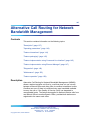
Alternative Call Routing for Network Bandwidth Management 127
Contents 127
Description 127
ALTPrefix 129
How Alternative Call Routing for NBWM works 130
Dialing plans 131
Examples of Alternative Call Routing for NBWM in operation 132
Operating parameters 143
Feature interactions 144
Call Redirections 144
Multiple Appearance Directory Number 144
Network Bandwidth Management 144
Nortel Communication Server 1000
Branch Office Installation and Commissioning
NN43001-314 01.02 Standard
Release 5.0 20 June 2007
Copyright © 2007, Nortel Networks
.
8 Contents
Network Class of Service 144
Network Routing Service (NRS) 145
Trunk Route Optimization (TRO) 145
Virtual Office 145
Feature packaging 145
Feature implementation using Command Line Interface 145
Task summary list 145
Sample printout 146
Feature implementation using Element Manager 147
Zone configuration 147
Diagnostics 149
Maintenance 155
Command Line Interface maintenance 155
Element Manager maintenance 155
Feature operation 158
How the Branch Office feature works
Contents 159
Introduction 160
Normal Mode and Local Mode operation 160
Normal Mode 160
Local Mode 160
Virtual Trunks 164
IP Phone calls 165
Zones 165
Vacant Number Routing 165
Time of Day 166
MG 1000B IP Phone to local PSTN calls 166
IP Phone to analog (500/2500-type) or digital telephone calls 167
Conference calls 167
Group Call 168
Configuring non-zero S2 IP Addresses 169
Points to remember 170
Configuring the S2 IP Address parameter 171
Multiple Appearance DN (MADN) 172
IP Phones with the same DN at the Branch Office 172
IP Phones with the same DN at the main office 172
Emergency services 172
Configuring ESA for emergency services 173
Configuring SPN for emergency services 174
Abbreviated Dialing 174
MG 1000B Core interoperability 176
Network Wide Redundancy Phase II and Network Music 176
Nortel Communication Server 1000
Branch Office Installation and Commissioning
NN43001-314 01.02 Standard
Release 5.0 20 June 2007
Copyright © 2007, Nortel Networks
.
159
Contents 9
Planning and management
179
Contents 179
Data network planning 179
LAN/WAN bandwidth requirements 180
Branch Office dialing plan 181
Emergency Services 182
Zones 182
Music on Hold 182
ESN Access Codes 182
Provisioning the IP Phones 182
Configuration example for PSTN resources at the Branch Office 183
Management 185
Remote Access 185
Element Manager 185
Telephony Manger 3.1 186
Set-Based Installation for IP Phones 186
Traffic measurement 186
Call Detail Recording (CDR) 187
Proactive Voice Quality management 188
System security 189
Adding a Branch Office
191
Contents 191
Introduction 191
Main office requirements 192
Optional features 193
Branch Office requirements 193
Implementation summary 194
Adding a CS 1000 Release 5.0 Branch Office to a Branch Office with a previous
software release 196
Upgrade the entire network to CS 1000 Release 5.0 197
Upgrade only the main office to CS 1000 Release 5.0 198
Converting a Small System to a Branch Office
Contents 201
Introduction 201
Requirements 201
Conversion 202
Implementation summary
203
Upgrading to CS 1000 Release 5.0
Contents 207
Introduction 207
Upgrading to CS 1000 Release 5.0
208
Nortel Communication Server 1000
Branch Office Installation and Commissioning
NN43001-314 01.02 Standard
Release 5.0 20 June 2007
Copyright © 2007, Nortel Networks
.
201
207
10 Contents
Main office configuration
209
Contents 209
Introduction 209
Zone parameters 210
Element Manager zone configuration 213
IP Phone passwords and parameters 215
MG 1000B IP Phone configuration 218
MG 1000B IP Phone configuration using TM 3.01 218
MG 1000B IP Phone configuration using LD 11 218
MG 1000B platform hardware installation
221
Contents 221
Installing an MG 1000B Core 221
Readiness checklist 222
Rack-mounting an MG 1000B Core or MG 1000B Expander 223
Installing cards 227
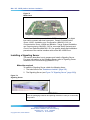
Installing a Signaling Server 228
Materials required 228
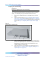
Preparing for rack-mounting 230
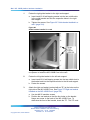
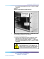
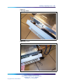
Rack-mounting 232
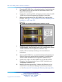
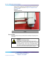
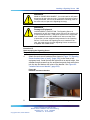
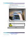
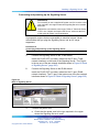
Connecting and powering up the Signaling Server 235
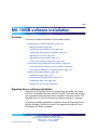
MG 1000B software installation
239
Contents 239
Signaling Server software installation 239
Materials required 240
Creating the Signaling Server CD 240
Installing the Signaling Server software 241
Upgrading the SIgnaling Server software 241
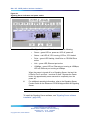
Signaling Server tools 241
Signaling Server port speed 243
Verifying a successful configuration 244
Connecting the MG 1000B Core to the network 244
Connecting the MG 1000B Core to the network 244
Using Element Manager to configure the node 247
Installing MG 1000B Hardware 249
Installing the cards 250
Installing a DSP Daughterboard 250
Installing the MGC card 251
Installing the CP PM card 252
Branch Office configuration
Contents 255
Configuring the Branch Office
255
Nortel Communication Server 1000
Branch Office Installation and Commissioning
NN43001-314 01.02 Standard
Release 5.0 20 June 2007
Copyright © 2007, Nortel Networks
.
255
Contents 11
Summary of steps 255
Configuring the Media Cards 256
Configuring the trunks and lines 256
Zone parameters 256
Element Manager Branch Office zone configuration 260
Adding the Branch Office endpoints to the NRS database 260
MG 1000B telephones
263
Contents 263
Overview 263
Installing and configuring IP Phones 264
Password requirements 265
Installing an IP Phone using the keypad 265
Branch User Config 270
Transferring IP Phone data using TM 3.01 274
Survivability test 276
Installing IP Phones through LD 11 279
Using the IP Phones 281
Telephone Options 282
Virtual Office Login on the Branch Office 284
Test Local Mode 286
Personal Directory, Callers List, Redial List 287
Set-Based Removal 287
Analog and digital devices in the Branch Office 288
Analog devices 288
Digital devices 288
Activating analog (500/2500-type) and digital telephones 289
Dialing plan configuration
Contents 291
Overview 291
Introduction 292
Dialing plans 292
Routing 294
SIP/H.323 zones 294
Bandwidth management zones 295
Zone-based digit manipulation 295
CLID composition 296
CLID verification 297
Configuring the dialing plan for PSTN access to Branch Users in Normal Mode
Preparing to configure the dialing plan 297
Configuring the dialing plan 298
Dialing plan configuration using Element Manager 311
Testing PSTN access using an MG 1000B IP Phone 312
Nortel Communication Server 1000
Branch Office Installation and Commissioning
NN43001-314 01.02 Standard
Release 5.0 20 June 2007
Copyright © 2007, Nortel Networks
.
291
297
12 Contents
Emergency Services configuration
315
Contents 315
Overview 315
Emergency Services Access (ESA) 316
Routing ESA calls 316
Configuring ESA for the Branch Office 317
Element Manager ESA configuration 326
Emergency Service using Special Numbers (SPN) 327
CLID verification (CLIDVER) 328
Networked M911 328
Basic Emergency Services When VO Logged Out
Contents 329
Overview 329
Configure ESA Data Block 333
Warm Start 333
Emergency Services For Client Mobility
Active Call Fail Over 334
Context Sensitive Soft Keys 334
Element Manager 335
329
333
Abbreviated Dialing configuration
337
Contents 337
Overview 337
Recommended configuration 337
Configuring Abbreviated Dialing 338
Maintenance and diagnostics
Contents 345
Firmware downloads 345
Enhanced UNIStim Firmware Download for IP Phones 345
Troubleshooting 349
Signaling Server CLI commands 354
isetShow 354
clearLockout TN or IP 354
Call Server commands 355
Verify CLID 355
Print Branch Office zone information 356
Enable/disable Branch Office zone features 357
View status of Branch Office zone at main office Call Server 357
Change/print PVQ notification levels 357
Print PVQ statistics 358
Print inventory 358
Nortel Communication Server 1000
Branch Office Installation and Commissioning
NN43001-314 01.02 Standard
Release 5.0 20 June 2007
Copyright © 2007, Nortel Networks
.
345
Contents 13
Appendix A Preprogrammed data
Contents 361
Introduction 361
Passwords and codes 362
Default numbering plan 362
First digits 363
Important extension numbers
Flexible Feature Codes 364
SDI ports 364
Modem port 365
ESDI settings 365
Telephone tones 366
Trunk routes 366
System parameters 367
Customer data 367
Trunk models 367
Telephone models 370
361
363
Appendix B Branch Office engineering example
Contents 371
Introduction 371
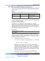
Assumptions 372
Calculations 373
Traffic 373
MG 1000B Core and MG 1000B Expander requirements
Bandwidth requirements 377
Branch Office conference engineering 379
371
375
Appendix C On-net dialing plan configuration examples
383
Contents 383
Introduction 383
Coordinated Dialing Plan 383
Uniform Dialing Plan 387
Call Scenarios 387
Configuration example 389
Group Dialing Plan 392
Call Scenarios 393
Configuration example 395
Transferable DN 399
Appendix D Off-net dialing plan configuration example
Contents 405
Introduction 405
Call scenario 405
Nortel Communication Server 1000
Branch Office Installation and Commissioning
NN43001-314 01.02 Standard
Release 5.0 20 June 2007
Copyright © 2007, Nortel Networks
.
405
14 Contents
Provisioning 406
Main office 406
NRS 408
Branch Office 409
Call example 409
Main office 410
NRS 410
Branch Office 410
List of terms
411
Procedures
Procedure
Procedure
Procedure
Procedure
Procedure
Procedure
Procedure
Procedure
Procedure
Procedure
Procedure
1
2
3
4
5
6
7
8
9
10
11
Procedure 12
Procedure 13
Procedure
Procedure
Procedure
Procedure
Procedure
Procedure
Procedure
Procedure
Procedure
Procedure
Procedure
Procedure
Procedure
Procedure
Procedure
Procedure
Procedure
Procedure
Procedure
Procedure
Procedure
Procedure
14
15
16
17
18
19
20
21
22
23
24
25
26
27
28
29
30
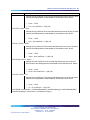
Printing intrazone and interzone statistics for a zone 67
Displaying CAC parameters for one or more zones 85
Provisioning Tandem Bandwidth Management 106
Accessing the Zones web page 147
Printing zone ALTPrefix 150
Show Status 153
Enabling a zones Branch Office behavior 156
Suppress Alternative Call Routing for NBWM alarms 157
Configuring ESN and MG 1000B zones 210
Setting the IP Phone Installers Password 215
Setting and changing the Station Control Password
Configuration 216
Configuring MG 1000B IP Phones at the main office using LD
11 218
Mounting the MG 1000B Core or MG 1000B Expander in a
19-inch rack 223
Preparing the Signaling Server for rack-mounting 230
Rack-mounting the Signaling Server 233
Connecting and powering up the Signaling Server 235
Creating a Signaling Server software CD-ROM 240
Viewing the Tools Menu 241
Changing the Signaling Server port speed 243
Verifying successful configuration 244
Configuring the ELAN network interface IP address 246
Connecting the Ethernet ports 247
Removing the SSC card 250
Installing a DSP Daughterboard 251
Installing the MGC card 252
Installing the CP PM card 252
Configuring the MG 1000B zone 257
Using Set-Based Installation 267
Configuring a Branch User 271
Using the Reports and Import Facility in TM 274
Testing the telephone for survivability 278
Installing IP Phones through overlays 279
Changing the SCPW 282
Using the Telephone Options feature 282
Using the Virtual Office Login feature 284
Nortel Communication Server 1000
Branch Office Installation and Commissioning
NN43001-314 01.02 Standard
Release 5.0 20 June 2007
Copyright © 2007, Nortel Networks
.
Contents 15
Procedure
Procedure
Procedure
Procedure
Procedure
Procedure
Procedure
Procedure
Procedure
Procedure
Procedure
Procedure
Procedure
Procedure
Procedure
Procedure
Procedure
Procedure
Procedure
Procedure
31
32
33
34
35
36
37
38
39
40
41
42
43
44
45
46
47
48
49
50
Procedure 51
Procedure 52
Procedure 53
Using the Test Local Mode feature 286
Using the Set-Based Removal feature 288
Configuring the main office 299
Configuring the NRS database 306
Configuring the Branch Office 308
Testing PSTN access using an MG 1000B IP Phone 312
Configuring the main office 319
Configuring the Branch Office 324
Configuring the Branch Office zone 325
Testing ESDN using an MG 1000B Telephone 326
Configuring Speed Call List (SCL) 339
Configuring Pretranslation Groups 340
Assigning Pretranslation Groups to the telephones 341
Configuring Incoming DID Digit Conversion (IDC) 342
Upgrading firmware for CS 1000 Release 5.0 347
Upgrading firmware for CS 1000 Release 4.0 and earlier 348
Calculating traffic 373
Calculating Call Server Loading 375
Calculating TLAN subnet bandwidth for IP Phone traffic 377
Calculating MG 1000B with Virtual Trunk
LAN/WAN 378
Calculating unspecified conference traffic 379
Calculating known conference traffic 380
Calculating Branch Office traffic, and LAN/WAN
bandwidth without local messaging
(CallPilot) capability 381
Nortel Communication Server 1000
Branch Office Installation and Commissioning
NN43001-314 01.02 Standard
Release 5.0 20 June 2007
Copyright © 2007, Nortel Networks
.
16 Contents
Nortel Communication Server 1000
Branch Office Installation and Commissioning
NN43001-314 01.02 Standard
Release 5.0 20 June 2007
Copyright © 2007, Nortel Networks
.
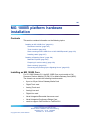
17
New in this release
This document is a global document. Contact your system supplier or your
Nortel representative to verify that the hardware and software described
are supported in your area.
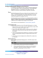
This document describes the Branch Office feature and contains information
on planning, installation, configuration, and maintenance. Information
in this document complements information found in documents in the
Communication Server 1000 documentation suite, as listed in Related
information.
This NTP contains information about systems, components, and features
that are compatible with Nortel Communication Server 1000 Release 5.0
software. For more information on legacy products and releases, click the
Technical Documentation link under Support on the Nortel home page:
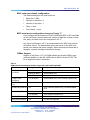
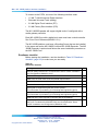
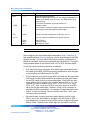
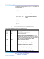
Table 1
Contents
"MG 1000B hardware platform" (page 17)
"Media Card MC32S" (page 18)
"Main and Branch Office running different releases" (page 18)
"Main Office and Branch Office Migration" (page 18)
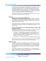
MG 1000B hardware platform
The MG 1000B system has been enhanced for CS 1000 Release 5.0
Branch Office. The CP-PM Call Server and MGC replace the Small System
Controller (SSC) used in the Release 4.0 and 4.5 MG 1000B.
Two new DSP Daughterboards are included in the CS 1000 portfolio of
products. The daughterboards are available in two different sizes, a 32-port
daughterboard and a 96-port daughterboard. These daughterboards are
located on the Media Gateway Controller card to provide DSP resources
for connecting IP and TDM devices, and eliminate the need to install the
Voice Gateway Media Cards within the CS 1000E Media Gateways (MG
1000B) chassis.
Nortel Communication Server 1000
Branch Office Installation and Commissioning
NN43001-314 01.02 Standard
Release 5.0 20 June 2007
Copyright © 2007, Nortel Networks
.
18 New in this release
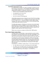
Media Card MC32S
For CS 1000 Release 5.0, the new Media Card 32S (MC32S) fully replaces
the functionality of the current VGMV pack NTVQ01BB. You can use the
new pack in both large and small systems, and anywhere you can use the
current NTVQ01BB pack. The MC32S also adds SRTP security. For an
MGC-based MG 1000B, the sets are configured in four-field format.
As there are new conference capabilities on the MGC, the Group Call
feature available in CS 1000 Release 5.0 on the CS 1000B is enhanced.
The number of group members increases from 6 to 20.
Main and Branch Office running different releases
If the main office Call Server is running CS 1000 Release 5.0, the Branch
Office can run on CS 1000 Release 5.0, CS 1000 Release 4.5, or CS 1000
Release 4.0.
Customers will no longer be permitted to order a Branch Office running on
Succession 3.0.
Main Office and Branch Office Migration
All Main Office call servers in CS 1000 Release 5.0 are large system based.
A CS 1000 Small System Main Office is no longer supported. Since all CS
1000 Release 5.0 Small System Controller (SSC) based Main Offices have
been migrated to Call Processor Pentium Mobile (CP-PM) Call Servers, the
Main Office TN (MOTN) Type in a Branch Office will always be set to the
large system MOTN Type.
In a system where the Main Office has been migrated from a SSC to CP-PM
call server, the LD 20 PRT on the branch will not correctly display the MOTN
using the small system TN format until the branch has been migrated or
upgraded to CS 1000 Release 5.0. In the case where the branch is SSC
based, the LD 20 PRT will remain incorrect until the Branch Office Call
Server has been migrated to a CP-PM call server. In the case where the
branch is already linked to a Large System Format Call Server, the LD 20
PRT report on the branch will remain incorrect until the branch has been
upgraded to CS 1000 Release 5.0.
Nortel Communication Server 1000
Branch Office Installation and Commissioning
NN43001-314 01.02 Standard
Release 5.0 20 June 2007
Copyright © 2007, Nortel Networks
.
19
How to get help
This chapter explains how to get help for Nortel products and services.
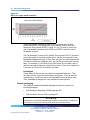
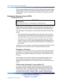
Getting help from the Nortel web site
The best way to get technical support for Nortel products is from the Nortel
Technical Support web site:
http://www.nortel.com/support
This site provides quick access to software, documentation, bulletins, and
tools to address issues with Nortel products. From this site, you can:
•
download software, documentation, and product bulletins
•
search the Technical Support Web site and the Nortel Knowledge Base
for answers to technical issues
•
sign up for automatic notification of new software and documentation
for Nortel equipment
•
open and manage technical support cases
Getting help over the telephone from a Nortel Solutions Center
If you do not find the information you require on the Nortel Technical Support
web site, and you have a Nortel support contract, you can also get help over
the telephone from a Nortel Solutions Center.
In North America, call 1-800-4NORTEL (1-800-466-7835).
Outside North America, go to the following web site to obtain the telephone
number for your region:
http://www.nortel.com/callus
Getting help from a specialist by using an Express Routing Code
To access some Nortel Technical Solutions Centers, you can use an Express
Routing Code (ERC) to quickly route your call to a specialist in your Nortel
product or service. To locate the ERC for your product or service, go to:
Nortel Communication Server 1000
Branch Office Installation and Commissioning
NN43001-314 01.02 Standard
Release 5.0 20 June 2007
Copyright © 2007, Nortel Networks
.
20 How to get help
http://www.nortel.com/erc
Getting help through a Nortel distributor or re-seller
If you purchased a service contract for your Nortel product from a distributor
or authorized re-seller, contact the technical support staff for that distributor
or re-seller.
Nortel Communication Server 1000
Branch Office Installation and Commissioning
NN43001-314 01.02 Standard
Release 5.0 20 June 2007
Copyright © 2007, Nortel Networks
.
21
Overview
Contents
This section contains information on the following topics:
"What is Branch Office?" (page 22)
"Main Office and Branch Office Migration" (page 24)
"MG 1000B (MGC) compared to the MG 1000B (SSC)" (page 24)
"MGC Serial Ports" (page 26)
"Single CPU Implications" (page 26)
"Dual CPU Implications" (page 26)
"Terminal Server Support" (page 26)
"MGC serial port default configuration" (page 27)
"MGC serial ports configuration change in Overly 17" (page 27)
Table 2 "CEMux Packs and daughter boards supported in MG 1000B with
MGC" (page 27)
"CEMux Support" (page 27)
"Clock References" (page 28)
"Main office hardware description" (page 28)
"MG 1000B platform hardware description" (page 29)
"MG 1000B Core" (page 31)
"MG 1000B Chassis" (page 32)
"MG 1000B Expander" (page 33)
"Signaling Server" (page 34)
"Telephones" (page 36)
"Voice Gateway Media Card" (page 37)
"Analog or digital trunk cards" (page 38)
"Analog or digital line cards" (page 38)
"Lineside cards" (page 38)
"MG 1000B with MGC Data Networking" (page 38)
Nortel Communication Server 1000
Branch Office Installation and Commissioning
NN43001-314 01.02 Standard
Release 5.0 20 June 2007
Copyright © 2007, Nortel Networks
.
22 Overview
"MGC Network Connections" (page 40)
"MG 1000B platform configuration overview" (page 44)
"MG 1000B platform without an MG 1000B Expander" (page 45)
"MG 1000B platform with an MG 1000B Expander" (page 46)
"Capacity" (page 47)
"Media Card DSP capacity" (page 47)
"Software requirements" (page 47)
"Main and Branch Office running the same release" (page 47)
"Main and Branch Office running different releases" (page 48)
"Package Combinations" (page 50)
"Supported applications" (page 50)
"Survivability" (page 50)
"Active Call Failover" (page 52)
"Configuring S2 IP Address to point to the main office TPS" (page 53)
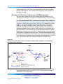
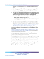
What is Branch Office?
The Branch Office feature extends CS 1000 features from a main office to
one or more remote offices.
The Branch Office feature is implemented on a Media Gateway 1000B
(MG 1000B) platform. The MG 1000B platform includes an MG 1000B
Core connected to an IP PBX at the main office over a LAN or a WAN. This
configuration enables a secondary location to centralize the call processing
of its IP-based communication network. The Call Server at the main office
provides the call processing for the IP Phones in both the main office and
Branch Office locations. The MG 1000B Core provides call processing
functionality to local digital telephones and analog devices. The MG 1000B
Core also provides digital and analog trunk access to the local Public
Switched Telephone Network (PSTN).
The MG 1000B platform connects to the main office over Virtual Trunks on
a LAN/WAN. The main office transmits and controls IP Phone calls and
IP network connections. If the main office fails to function, or if there is
a network outage, the Media Gateway Controller (MGC) card in the MG
1000B Core provides service to the telephones located at the Branch Office
location. This enables the IP Phones to survive the outage between the
Branch Office and the main office.
Currently, MG 1000B Branch Office is small system based; which is still
supported in CS 1000 Release 5.0. In addition, changes are made to
allow large system based branch offices. Branch Office configurations
supported in CS 1000 Release 5.0, and are not changed with the CP PM
(Call Processor Pentium Mobile). Additionally, the CP PM adds the ability
Nortel Communication Server 1000
Branch Office Installation and Commissioning
NN43001-314 01.02 Standard
Release 5.0 20 June 2007
Copyright © 2007, Nortel Networks
.
What is Branch Office? 23
for large systems to be supported as a Branch Office. A mixture of pre
CS 1000 Release 5.0 branches are supported with CS 1000 Release 5.0
branches as long as the main office is running the latest software.
The Branch Office feature does not change with the addition of large system
based branches. The Branch Office feature is ported to a large system.
Both small and large systems are supported as either main or branch
offices with only one restriction; the main must be running the highest
release of software.
Support is available for CS 1000 Release 5.0 Branch Office features, as
long as the main office is running the highest release of software. For
example, Branch offices can be either the SSC based MG 1000B (CS 1000
Release 4.5), or the new MGC based MG 1000B (CS 1000 Release 5.0).
With CS 1000 Release 5.0 and the introduction of the new hardware
platforms, the following configurations are supported:
•
Main Office: MGCbased system. Branch Office: MGC based MG
1000B.
•
Main Office: MGC based system. Branch Office: MGC based MG
1000B (large system software stream).
•
Main Office: Large system (1000M or 1000E). Branch Office: MGC
based MG 1000B.
•
Main Office: Large system (1000M or 1000E). Branch Office: MGC
based MG 1000B (large system software stream).
For small Branch Office configurations, the Survivable Remote Gateway
feature can provide the same functionality and benefits as the Branch Office
feature.
You can implement the Branch Office feature as a new hardware
configuration. It can also be created by converting an existing Small System
to an MG 1000B platform (see "Converting a Small System to a Branch
Office" (page 201)). The functionality is the same in both configurations.
The main office can be any one of the CS 1000 systems (see ""Main office
hardware description" (page 28)" More than one Branch Office location
can be associated with a single main office. In addition, one Branch Office
location can be associated with more than one main office.
A Branch Office is designed to work with a main office only if the two offices
use a common dialing plan. Any other configuration is not guaranteed to
work properly.
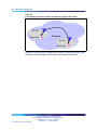
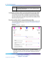
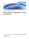
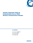
Figure 1 "Branch Office associated with a CS 1000E main office" (page
24) shows a Branch Office network.
Nortel Communication Server 1000
Branch Office Installation and Commissioning
NN43001-314 01.02 Standard
Release 5.0 20 June 2007
Copyright © 2007, Nortel Networks
.
24 Overview
Figure 1
Branch Office associated with a CS 1000E main office
Main Office and Branch Office Migration
All Main Office call servers in CS 1000 Release 5.0 are large system based.
A CS 1000 Small System Main Office is no longer supported. Since all CS
1000 Release 5.0 Small System Controller (SSC) based Main Offices have
been migrated to Call Processor Pentium Mobile (CP-PM) Call Servers, the
Main Office TN (MOTN) Type in a Branch Office will always be set to the
large system MOTN Type.
In a system where the Main Office has been migrated from a SSC to CP-PM
call server, the LD 20 PRT on the branch will not correctly display the MOTN
using the small system TN format until the branch has been migrated or
upgraded. In the case where the branch is SSC based, the LD20 PRT will
remain incorrect until the Branch Office Call Server has been migrated to a
CP-PM call server. In the case where the branch is already a large system
(CP-PII or CP-PIV), then the LD 20 PRT on the branch will remain incorrect
until the branch has been upgraded to CS 1000 Release 5.0.
MG 1000B (MGC) compared to the MG 1000B (SSC)
The MG 1000B with MGC has a number of differences in hardware
capability when compared with Release 4.5 gateways.
The MGC has six Ethernet interfaces for connecting to external networking
equipment. Three are reserved for ELAN connections and three are
reserved for TLAN1 connections. The six external Ethernet interfaces on
the MGC are set to Auto Negotiate mode by default. You can change the
settings for ports 1E, 2T, E and T to 100 Mbps full duplex by using the
Nortel Communication Server 1000
Branch Office Installation and Commissioning
NN43001-314 01.02 Standard
Release 5.0 20 June 2007
Copyright © 2007, Nortel Networks
.
MG 1000B (MGC) compared to the MG 1000B (SSC) 25
mgcsetup command. With a properly designed data network, the multiple
ELAN and TLAN interfaces can be used to implement a dual homed
configuration for the MG 1000B with MGC.
Four of these interfaces are accessed by using RJ45 connectors on the
faceplate. Two are reserved for ELAN and two are reserved for TLAN.
Two additional Ethernet connections are available if an Option 11C cabinet
is used. One is reserved for ELAN and one is reserved for TLAN.
For the Option 11C cabinets, to break out the two new 100BaseT Ethernet
connections, you need a new backplane adapter. This adapter replaces
the MDF-to-AUI cable used for the 10BaseT Ethernet connection on the
existing system.
One use for the additional LAN connections is to allow for network
redundancy, also known as dual-homing on the Release 4.5 MG 1000B.
The MGC Ethernet interface failover is accomplished with the embedded
Ethernet switch. The Ethernet interface failover feature requires no special
network configuration to function. The end customer decides if two separate
Layer 2 switches are used to implement the feature to minimize the service
outage. For more information see the Communication Server 1000E:
Installation and Configuration (NN43041-310) NTP.
Also, you can use the broadcast and multi cast rate limiting features of the
embedded Ethernet switch on the MGC to reduce the susceptibility of the
Call Server to broadcast storms and similar network issues, if you directly
cable the Call Server to the MGC.
In addition, certain debug features use the LAN connections (for example,
port mirroring.)
The MGC has two conference loops with thirty units each. The maximum
number of participants in a conference is thirty. On the MG 1000B, the
maximum number of conference loops was four with sixteen units in each
loop. The maximum number of participants in a conference was six.
The MGC has a four-character alphanumeric LED display on the faceplate.
the boot and application software use the display to show diagnostic
information to the technician.
The MGC has a clock reference input/output to support the requirements
of the Digital Enhanced Cordless Telecommunications (DECT) standard.
The DECT product requires a tight clock tolerance between cabinets with
interconnected radio equipment of ±5ppm. To accommodate the tight clock
Nortel Communication Server 1000
Branch Office Installation and Commissioning
NN43001-314 01.02 Standard
Release 5.0 20 June 2007
Copyright © 2007, Nortel Networks
.
26 Overview
tolerance, the MGC is equipped with a clock reference input/output. The
clock reference input and output connections and cable detect are provided
through a 15-pin DSUB connector.
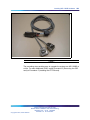
MGC Serial Ports
Each MGC installed in a CS 1000B provides the opportunity for 3 remote
SDIs. The maximum number of TTYs does not change. Therefore, after you
configure the maximum TTYs , no additional TTYs are supported.
The MGC has three serial ports SDI0, SDI1, and SDI2.
You can use serial ports for local debugging; or, you can configure the ports
in the MG 1000B Call Server as system terminals in LD 17.
During the initial configuration of the MGC, you must connect to either
SDI0 or SDI1 to access the installation menu. Only SDI0 has full modem
support, as SDI1 and SDI2 have no hardware flow control (limitation of
the three-port cable used).
SDI2 is not available during the MGC bootup; therefore, you cannot use
it to access the installation menus.
Unlike the NTDK20xx SSC card, all SDI ports on the MGC are configured
by using shipped software. No DIP switches are on the MGC for configuring
the baud rate of SDI0.
Single CPU Implications
Single CPU installations do not require dynamic binding of TTY ports to
the active CPU because only one CPU exists. Therefore, single-CPU
installations can use the Call Server TTY ports or the MGC remote TTY
ports.
Dual CPU Implications
MG 1000B uses a terminal server to ensure that serial ports are always
bound to the active CPU. The remote SDIs on the MGC provide similar
functionality. Each MGC provides three SDI ports that you can provision
in the softswitch as TTYs.
Remote TTY provisioning is enhanced over the terminal server model. SDI
port provisioning is performed on the softswitch and does not require local
provisioning at the IPMG.
Terminal Server Support
The remote SDI feature on the MGC eliminates the need for a terminal
server.
Nortel Communication Server 1000
Branch Office Installation and Commissioning
NN43001-314 01.02 Standard
Release 5.0 20 June 2007
Copyright © 2007, Nortel Networks
.
MGC Serial Ports
27
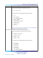
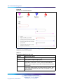
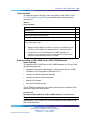
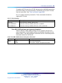
MGC serial port default configuration
The default settings for the serial ports are
•
Baud rate = 9600
•
Number of data bits = 8
•
Number of stop bits = 1
•
Parity = none
•
Flow control = none
MGC serial ports configuration change in Overly 17
If you configure the serial ports on an MG 1000B with MGC as SL1 terminals
on the Call Server, then the baud rate, number of data bits, number of stop
bits, parity, and flow control are configured in LD 17.
Any values configured in LD 17 are downloaded to the MGC and override
the default values. The downloaded values are stored on the MGC and
persist over restarts and power outages. When the serial port baud rate is
changed, a system message indicates the change.
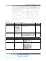
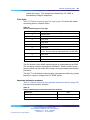
CEMux Support
Support of the Option 11C CS 1000M cabinet and chassis CEMux type
cards are additions to the MG 1000B with an MGC with the CP PM. The
list of supported cards is as follows:
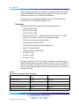
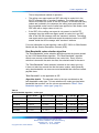
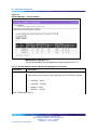
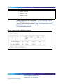
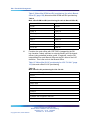
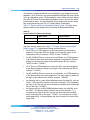
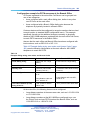
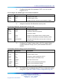
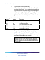
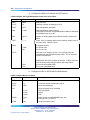
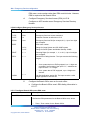
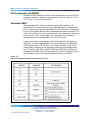
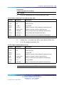
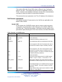
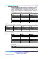
Table 2
CEMux Packs and daughter boards supported in MG 1000B with MGC
Pack
Daughterboard
IP Expansion CEMux Application
1.5MB DTI/PRI
(NTAK09)
DCHI (NTAK93)
non-downloadable DCH
DDCH (NTBK51)
downloadable DCH
CC (NTAK20)
clock controller (stratum 3/4)
1.5MB TMDI
(NTRB21)
CC (NTAK20)
downloadable DCH, clock controller (stratum 3/4)
2.0MB DTI (NTAK
10)
n/a
clock controller (stratum 3/4)
2.0MB PRI (NTAK79)
n/a
clock controller (stratum 3/4), non-downloadable
DCH
2.0MB PRI (NTBK50)
DDCH (NTBK51)
downloadable DCH
CC (NTAK20
clock controller (stratum 3/4)
MISP (NTBK22)
CC (NTAK20)
MISP BRI processor, clock controller (stratum 3/4)
SDI_DCH (NTAK02)
n/a
only DCH is supported
Nortel Communication Server 1000
Branch Office Installation and Commissioning
NN43001-314 01.02 Standard
Release 5.0 20 June 2007
Copyright © 2007, Nortel Networks
.
28 Overview
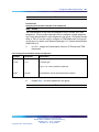
SSTD (NTAK03) not
supported
n/a
n/a
Card Option Mail not
supported
n/a
n/a
Standard Option 11C minimum vintages apply to all packs and daughter
boards.
Attempts to install unsupported CEMux packs or to configure an
unsupported application are blocked.
Support of CEMux requires CS 1000 Release 5.0 Softswitch software and
a Media Gateway Controller Card (MGC). It is supported by all MG 1000B
systems.
Features supported by Option 11C SIPE related to CEMux are supported in
MG 1000B, which includes support for nB+D by having single D-Channel
support trunk packs in separate MG1000Bs.
The TMDI D-Channel ISM used on small systems IS NOT included for the
CS 1000B. D-Channels configured or removed for TMDI cards increment
the existing large system software based DCH ISM. The maximum number
of D-Channels, which is 255, supported with CS 1000B in CS 1000 Release
5.0, matches that of the CS 1000M large systems.
For BRI, you must provision the MISP and the SILC/UILC in the same
IPMG. This is the only supported configuration.
Clock References
With CEMux support, you can configure digital trunks and clock controller
configuration in the IPMG. Each IPMG that contains a digital trunk card
requires a clock controller on that shelf. You cannot use Clock references
across IPMGs, and you can configure only one clock controller per shelf..
Main office hardware description
The main office must be one of the following systems:
•
CS 1000E
•
CS 1000M Cabinet
•
CS 1000M Chassis
•
CS 1000M HG
•
CS 1000M SG
•
CS 1000M MG
Nortel Communication Server 1000
Branch Office Installation and Commissioning
NN43001-314 01.02 Standard
Release 5.0 20 June 2007
Copyright © 2007, Nortel Networks
.
MG 1000B platform hardware description
29
The diagrams throughout this document show a CS 1000E main office. All
of the systems appearing in the list perform identical main office functions
as far as the Branch Office feature is concerned.
MG 1000B platform hardware description
The MG 1000B system has been enhanced for CS 1000 Release 5.0 Branch
Office. The CP-PM Call Server and MGC replace the SSC (Motorola) used
in the Release 4.0/4.5 MG 1000B. The Voice Gateway Media Card is still
supported however, the DSPs are also available on the MGC.
Two new DSP Daughterboards are included in the CS 1000 portfolio of
products. The daughterboards are available in two different sizes, a 32-port
daughterboard and a 96-port daughterboard. These daughterboards are
located on the Media Gateway Controller (MGC) card to provide DSP
resources for connecting IP and TDM devices. These daughterboards
eliminate the need to instal the Voice Gateway Media Cards within the CS
1000E Media Gateways (MG 1000B) chassis, to save slots and reduce cost
over the current Voice Gateway Media Card solution. The addition of the
DSP Daughterboards into a MG 1000B system does not limit the use of
Voice Gateway Media Cards (either Pentium or Strong-Arm versions), either
for DSP-only functionality or for the full IP Line application within the same
system. The MGC is used only in the Media Gateway chassis or Option
11C-style cabinets. From a functional perspective, the DSP Daughterboards
behave in a similar manner as the current Voice Gateway (VGW) application
on the Voice Gateway Media Card.
Support exists for four configurations:
•
a system with no DSP DBs or Voice Gateway Media Card (A pure TDM
system, single media gateway).
•
a system with only Voice Gateway Media Cards
•
a system with only DSP DBs
— a 32-port daughterboard in daughterboard position 1
— a 32-port daughterboard in daughterboard position 2
— A 32-port daughterboard in daughterboard position 1 and a 32-port
daughterboard in daughterboard position 2
— a 96-port daughterboard in daughterboard position 1
— a 96-port daughterboard in daughterboard position 1 and a 32-port
daughterboard in daughterboard position 2
•
a system with DSP DBs (all of the position combinations described in c)
and Voice Gateway Media Cards.
The basic hardware of an MG 1000B platform includes the MG 1000B Core
and the Signaling Server.
Nortel Communication Server 1000
Branch Office Installation and Commissioning
NN43001-314 01.02 Standard
Release 5.0 20 June 2007
Copyright © 2007, Nortel Networks
.
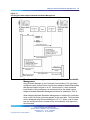
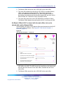
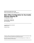
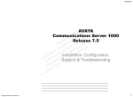
30 Overview
Figure 2
CS 1000 Release 5.0 MG 1000B System
CS 1000 Release 5.0 continues to support the existing Branch Office
configuration that uses the SSC processor, but Nortel no longer offers sales
of the SSC based Branch Office.
CS 1000 Release 5.0 provides various hardware versions of the Signaling
Server, the existing ISP1100 signaling servers, or the new CP-PM Signaling
Server.
With CS 1000 Release 5.0 Branch Office, the hardware configuration
includes a CP-PM call processor card with the MGC, as well as a CP-PM
Signalling Server. If the CP-PM Signalling Server configuration cannot be
used, the option exists to use the Signaling Server on COTS.
The MG 1000B Core and MG 1000B Expander can connect to either a
LAN or a WAN.
An MG 1000B platform can be a new hardware configuration. It can also
be a Small System platform converted to an MG 1000B platform. In the
latter case, the cabinet or chassis performs the same functionality as the
Nortel Communication Server 1000
Branch Office Installation and Commissioning
NN43001-314 01.02 Standard
Release 5.0 20 June 2007
Copyright © 2007, Nortel Networks
.
MG 1000B platform hardware description
31
MG 1000B Core, and the optional chassis expander performs the same
functionality as the MG 1000B Expander. Refer to "Converting a Small
System to a Branch Office" (page 201) for more information.
After conversion to an MG 1000B platform, the Small System cabinet or
chassis is referred to as an "MG 1000B Cabinet" or "MG 1000B Chassis",
as applicable. The optional chassis expander is referred to as the "MG
1000B Chassis Expander".
Throughout this document, the term "MG 1000B Core" can refer to an MG
1000B Cabinet or MG 1000B Chassis for a converted Small System, unless
otherwise indicated. Likewise, the term "MG 1000B Expander" can refer to
an MG 1000B Chassis Expander.
MG 1000B Core
The MG 1000B Core provides access to the local PSTN for users in the
Branch Office. It also provides support for digital telephones and analog
devices, such as fax machines and analog (500/2500-type) telephones
in the Branch Office.
Where required, the MG 1000B Core is connected by copper wire to the MG
1000B Expander for added capacity.
The MG 1000B Core must contain a CP-PM Call Server. The CP-PM Call
Server provides telephony services to elements at the Branch Office, such
as digital telephones, analog devices, digital trunks, and analog trunks.
It also provides call processing services to IP Phones when the phones
are registered to the MG 1000B Core (Local Mode). The MG 1000B Core
provides a dedicated slot (slot 0) for the CP PM. The software feature set on
the CP PM can differ from that of the Call Server at the main office.
The 10/100BaseT connection for the Embedded Local Area Network
(ELAN) and Telephony Local Area Network (TLAN) subnets, where the MG
1000B Core exists, is on the back of the MG 1000B Core.
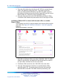
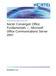
Figure 3 "MG 1000B Core/MG 1000B Expander" (page 32) shows an MG
1000B Core/MG 1000B Expander.
Nortel Communication Server 1000
Branch Office Installation and Commissioning
NN43001-314 01.02 Standard
Release 5.0 20 June 2007
Copyright © 2007, Nortel Networks
.
32 Overview
Figure 3
MG 1000B Core/MG 1000B Expander
MG 1000B Chassis
CEMux packs are supported in card positions 1 to 4 of an MG 1000B
chassis. They are not supported in the MG 1000B expander chassis, similar
to what is the support in the Option 11C SIPE system.
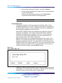
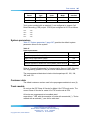
Card slots
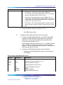
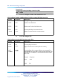
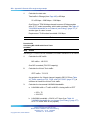
Table 3 "Card slots for MG 1000B Core and MG 1000B Expander" (page 32)
shows the card slot assignments for all configurations of the MG 1000B Core
and MG 1000B Expander (discussed on "MG 1000B Expander" (page 33)).
Table 3
Card slots for MG 1000B Core and MG 1000B Expander
MG 1000B
Configuration
MG 1000B Core
Total
Slot #
for
MG 1000B
Expander
Slot # for
48-port
Nortel Communication Server 1000
Branch Office Installation and Commissioning
NN43001-314 01.02 Standard
Release 5.0 20 June 2007
Copyright © 2007, Nortel Networks
.
Usable
Tota
l
Usable
MG 1000B platform hardware description
slots
33
MGC
DLC
slot #s
slot
s
slot #s
MG 1000B Core
5
0
Not used
1-4
4
7-10
MG 1000B Cabinet
11
0
Not used
1-10
(see
Note 1)
N/A
N/A
MG 1000B Chassis
5
0
4 (see
Note 2)
1-3
4
7-10
(see
Note 1)
For converted Small Systems only, the Meridian Mail card must be installed in slot 10 if Meridian
Mail is to be supported.
If the 48-port Digital Line Card (DLC) is not used, slot 4 must remain unused. However, it can be
covered by a double-slot card, such as an ITG-P card, inserted in slot 3.
In Table 3 "Card slots for MG 1000B Core and MG 1000B Expander" (page
32), the term "usable" denotes those card slots which are not reserved for,
or dedicated to, a specific card type. The following circuit cards can be
installed in any "usable" slot:
•
Media Cards
•
Digital Trunk cards
•
Analog Trunk cards
•
Analog Line cards
•
Digital Line cards
•
Nortel Integrated Recorded Announcer card
•
Nortel Integrated Conference Bridge card
•
cards to support CallPilot Mini or CallPilot 201i
The legacy 24-port ITG-P card, when upgraded to IP Line 4.5 software,
provides the same service as the Media Card. In this document, unless
otherwise noted, the ITG-P card can be substituted for the Media Card.
The Media Cards act exclusively as Voice Gateway Media Cards on the
MG 1000B platform.
MG 1000B Expander
The MG 1000B Expander can be used with all MG 1000B platform
configurations except the MG 1000B Cabinet. The MG 1000B Expander is
identical to the MG 1000B Core with the following exceptions:
•
Digital trunk cards are not supported in the MG 1000B Expander.
Nortel Communication Server 1000
Branch Office Installation and Commissioning
NN43001-314 01.02 Standard
Release 5.0 20 June 2007
Copyright © 2007, Nortel Networks
.
34 Overview
•
The MG 1000B Expander is connected to the MG 1000B Core with
copper wire. Therefore, the back of the MG 1000B Expander does not
have an Ethernet port.
Figure 3 "MG 1000B Core/MG 1000B Expander" (page 32) shows the MG
1000B Expander. Table 3 "Card slots for MG 1000B Core and MG 1000B
Expander" (page 32) gives the card slots for the MG 1000B Expander.
Signaling Server
The Signaling Server is required for the Branch Office feature. It provides
the following functions:
•
IP Peer Networking, incorporating:
— SIP and H.323 Gateways
— Network Routing Service (NRS), consisting of:
–
SIP Redirect Server
–
H.323 Gatekeeper
–
Network Connection Service (NCS)
•
IP Phone registration to the IP Phone Terminal Proxy Server (TPS)
during Local Mode for survivability
•
Web server for Element Manager and NRS Manager
A second Signaling Server can be used to provide redundancy in the case
of a failure in the other Signaling Server at the Branch Office. The NRS
must reside on the Leader Signaling Server.
A network requires one NRS. However, Nortel recommends that an
Alternate NRS, and in some cases at least one Failsafe NRS, be configured
in the network. In a Branch Office network, configuring a Primary or
Alternate NRS at a Branch Office location is not appropriate due to possible
network outages. For maximum coverage, Nortel recommends that a
Failsafe NRS be configured at each Branch Office location that is not
otherwise configured with a Primary or Alternate NRS.
In a SIP-enabled system, the Signaling Server supports only en bloc
signaling.
In an H.323-enabled system, the Signaling Server supports both en bloc
and overlap signaling. En bloc signaling is standard. If overlap signaling is
to be used, Nortel highly recommends that it be installed and enabled on all
Signaling Servers in the network. Failure to do so results in delays in call
completion due to overlap to en-bloc conversion.
Nortel Communication Server 1000
Branch Office Installation and Commissioning
NN43001-314 01.02 Standard
Release 5.0 20 June 2007
Copyright © 2007, Nortel Networks
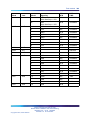
.
MG 1000B platform hardware description
35
For more information on the Signaling Server, refer to Signaling Server
Installation and Commissioning (NN43001-312). For more information on
SIP, H.323, and overlap signaling, refer to IP Peer Networking Installation
and Commissioning (NN43001-313) .
The NCS is required to provide the Main Office Node IP’s actual status. The
redirection procedure cannot be performed without the NCS. Interaction
with the NCS Branch Office requires the same H.323 ID to be configured for
each Branch Office node element (MGC). This H.323 ID exists in the NCS
(NRS H.323 Gatekeeper) Database. If there is no H.323 ID in the NCS
database, the NCS ignores the request for translation from the Branch user
ID (BUID) into associated Main office node IP. For more information on the
NCS, refer to "MG 1000B Core interoperability" (page 176) and "Adding the
Branch Office endpoints to the NRS database" (page 260).
Network Routing Service (NRS)
The NRS application provides network-based routing, combining the
following into a single application:
•
H.323 Gatekeeper — provides central dialing plan management and
routing for H.323-based endpoints and gateways.
•
SIP Redirect Server — provides central dialing plan management and
routing for SIP-based endpoints and gateways.
•
NRS Database — stores the central dialing plan in XML format for both
the SIP Redirect Server and the H.323 Gatekeeper. The SIP Redirect
Server and the H.323 Gatekeeper accesses this common endpoint and
gateway database.
•
Network Connect Server (NCS) — used only for Media Gateway
1000B (MG 1000B), SRG, Geographic Redundancy and Virtual Office
solutions. The NCS allows the Line TPS (LTPS) to query the NRS using
the UNIStim protocol.
•
NRS Manager web interface — the NRS provides its own web interface
to configure the SIP Redirect Server, the H.323 Gatekeeper, and the
NCS.
The NRS application provides routing services to both H.323 and
SIP-compliant devices. The H.323 Gatekeeper can be configured to support
H.323 routing services, while the SIP Redirect Server can be configured to
support SIP routing services. The H.323 Gatekeeper and the SIP Redirect
Server can reside on the same Signaling Server.
Each system in an IP Peer network must register to the NRS. The NRS
software identifies the IP addresses of systems based on the network-wide
numbering plan. NRS registration eliminates the need for manual
configuration of IP addresses and numbering plan information at every site.
Nortel Communication Server 1000
Branch Office Installation and Commissioning
NN43001-314 01.02 Standard
Release 5.0 20 June 2007
Copyright © 2007, Nortel Networks
.
36 Overview
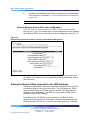
When configuring the NRS it is necessary to enable the NCS. Ensure the
check box "Network Connection Server enabled" is checked in the NRS
configuration window of CS 1000 Element Manager.
For information on configuring the NRS, refer to IP Peer Networking
Installation and Commissioning (NN43001-313) .
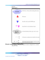
Telephones
The Branch Office feature supports the following telephones:
•
Nortel IP Phone 2001
•
Nortel IP Phone 2002
•
Nortel IP Phone 2004
•
Nortel IP Phone 2007 — configured as IP Phone 2004. In CS 1000
Release 5.0, IP phone 2007 can be configured as itself.
•
IP Phone Key Expansion Module (KEM)
•
WLAN Handset 2210/2211/2212
•
Analog (500-2500 type) and digital telephones
•
Nortel IP Softphone 2050
•
Nortel Mobile Voice Client 2050
•
IP Phone 1120E
•
IP Phone 1140E
•
IP Phone 1150E
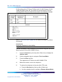
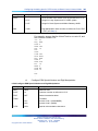
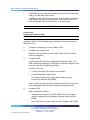
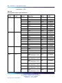
Naming of existing IP Phone TN Types is changed to be consistent with
latest IP Phone naming convention. Below is a table of Rls 4.5 and Rls 5.0
IP Phone TN Types. You can no longer use old names in the overlays, so
when the system administrator tries to use any of the old names, new SCH
message is printed.
Table 4
New IP Phone TN type naming convention
IP Phone Model Name
CS 1000 Release 4.5 TN
Type
CS 1000 Release 5.0 TN Type
IP Phone 2001
i2001
2001P2
IP Phone 2002 Phase I
i2002
2002P1
IP Phone 2002 Phase II
i2002
2002P2
IP Phone 2004 Phase 0/1
i2004
2004P1
IP Phone 2004 Phase II
i2004
2004P2
Nortel Communication Server 1000
Branch Office Installation and Commissioning
NN43001-314 01.02 Standard
Release 5.0 20 June 2007
Copyright © 2007, Nortel Networks
.
MG 1000B platform hardware description
IP Audio Conference Phone
2033
i2001
2033
IP Softphone 2050
i2050
2050PC
Mobile Voice Client 2050
i2050
2050MC
WLAN Handset 2210
i2004
2210
WLAN Handset 2211
i2004
2211
WLAN Handset 2212
i2004
2212
IP Phone 1110
i2001
1110
IP Phone 2007
i2004
2007
IP Phone 1120E
i2004
1120
IP Phone 1140E
i2004
1140
IP Phone 1150E
iPACD
1150
37
Throughout this document, the telephones in this list are referred to
collectively as "IP Phones." IP Phones in the Branch Office are referred
to as "Branch Users."
In an H.323-enabled system, the IP Phones are provisioned in the Branch
Office using Set-Based Installation, Command Line Interface (CLI) overlays,
or Telephony Manager 3.1 (TM 3.1).
Firmware download
The Enhanced UniStim Firmware Download for IP Phones feature provided
an improved method of delivering new firmware to Nortel IP Phones.
For further information on the Enhanced UniStim Firmware Download for IP
Phones feature, refer to IP Line Fundamentals (NN43100-500).
Voice Gateway Media Card
For CS 1000 Release 5.0, the new Media Card 32S (MC32S) fully replaces
the functionality of the current VGMV pack NTVQ01BB. You can use the
new pack in both large and small systems, and anywhere you can use
the current NTVQ01BB pack. The MC32S also adds SRTP security. For
an MGC-based MG 1000B, the sets are configured in four-field format.
For additional information, see theIP Line: Description and Information
(NN43100-500)NTP or theCircuit Card: Description and Installation
(NN43001-311)NTP.
The Media Card acts as a Voice Gateway Media Card, providing a pool of
Digital Signal Processor (DSP) ports for media transcoding between IP
voice packets and circuit-switched resources. The card comes equipped
with DSP modules. Each call between an IP Phone and an analog
Nortel Communication Server 1000
Branch Office Installation and Commissioning
NN43001-314 01.02 Standard
Release 5.0 20 June 2007
Copyright © 2007, Nortel Networks
.
38 Overview
(500/2500-type) or digital telephone or the PSTN uses one DSP port. Calls
between two IP Phones do not require any DSP ports, as there is no need
for IP-to-circuit-switched transcoding.
Media Cards provide echo cancellation, compression, and decompression
of voice streams.For more information about DSP resources residing on the
MGC that are configured with DSP Daughterboards, see the CS 1000E
Installation and Configuration NTP.
The ITG-P card uses two card slots in the MG 1000B Core, whereas the
Media Card uses one card slot.
Analog or digital trunk cards
All analog and digital trunk interfaces supported on CS 1000 systems are
also supported by the Branch Office feature. Analog and digital trunk cards
interface with the PSTN. For information on trunk cards, refer to Circuit Card
Reference(NN43001-311).
Analog or digital line cards
Analog (500/2500-type) or digital telephones and devices are supported by
the Branch Office feature. For information about line cards, refer to Circuit
Card Reference(NN43001-311).
When additional digital and analog (500/2500-type) telephones are located
in the Branch Office, additional DSP resources are required. Refer to
"Media Card DSP capacity" (page 47).
Lineside cards
MG 1000B supports the following lineside cards:
•
NTD514 line side T1
•
NTD534 line side E1
For further information about T1/E1 lineside cards, refer to Circuit Card
Reference(NN43001-311).
MG 1000B with MGC Data Networking
MG 1000B with MGC shelves communicates with the Call Server using
the built-in 100BaseT Ethernet Interface on the MGC. Three Ethernet
ports on the MGC can be used to connect to the ELAN, two for use by
the dual-homing feature and one for a direct connection to a Call Server
platform.
Nortel Communication Server 1000
Branch Office Installation and Commissioning
NN43001-314 01.02 Standard
Release 5.0 20 June 2007
Copyright © 2007, Nortel Networks
.
MG 1000B with MGC Data Networking
39
You can connect the MGC to a Layer 2 switch to handle signaling between
the Call Server and the MG 1000Bs. If two of the MGC ELAN ports connect
to separate Layer 2 switches, the MG 1000B can remain operational if one
of the Layer 2 switches fails.
MG 1000B shelves must have a data network connectivity to the ELAN
port of the Call Server. The design of the data networking configuration is
outside the scope of this document. The engineering of the data network is
documented in the Data Networking for Voice over IP (NN43001-260) NTP.
The MG 1000B with MGC by default supports Auto Negotiate mode on
the embedded Ethernet interfaces; you must configure the networking
equipment to which they connect as Auto Negotiate. If the MGC Ethernet
ports do not auto-negotiate to 100 Mb Full Duplex, an alarm occurs, as
issues can arise if the speed is not 100 Mb, and if the duplex is only half. A
CLI command is also available on the MGC to turn off auto-negotiation for
the embedded Ethernet interfaces, which configures the interfaces to 100
MB Full Duplex. No other speed or duplex options are available on the MGC.
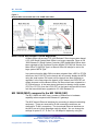
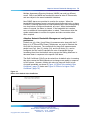
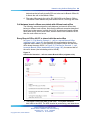
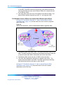
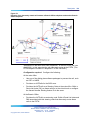
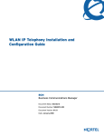
CS 1000B/MG 1000B with MGC - Data Network Topology illustrates a
typical robust network topology.
Figure 4
CS 1000B and MG 1000B with MGC - Data Network Topology
Nortel Communication Server 1000
Branch Office Installation and Commissioning
NN43001-314 01.02 Standard
Release 5.0 20 June 2007
Copyright © 2007, Nortel Networks
.
40 Overview
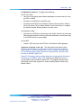
MGC Network Connections
In the following diagrams, two connections are shown to the external data
equipment for the dual-homing feature, distributed and nondistributed.
Nondistributed means that both Ethernet ports (TLAN or ELAN) of the
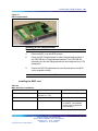
dual-homing feature connect to a single Layer 2 switch, thus providing a
single point of failure if that switch goes out of service.
Distributed means that the two Ethernet ports (TLAN or ELAN) of the
dual-homing feature connect to separate Layer 2 switches, to provide
another level of redundancy and no single point of failure with a Layer 2
switch. Nortel recommends distributed connections; support is available for
nondistributed connections if the cost of the additional data networking
equipment is an issue.
The CE and CT ports on the MGC are the only embedded Ethernet ports
that allow a direct connection to another device, and the only card supported
for this direct connection is the CP-PM Call Server. For a cascading
configuration, you can use the 1E and 1T ports can be used to connect
to another MGC card.
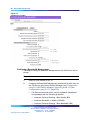
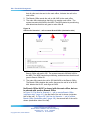
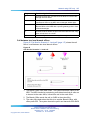
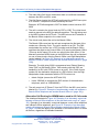
The figure below shows the supported configuration for a single server
configuration without redundant network configurations. This is the standard
configuration of a cost effective single server configuration. A single server
supports multiple MGCs using external networking equipment.
Figure 5
Single server port network connections (no dual-homing)
Nortel Communication Server 1000
Branch Office Installation and Commissioning
NN43001-314 01.02 Standard
Release 5.0 20 June 2007
Copyright © 2007, Nortel Networks
.
MG 1000B with MGC Data Networking
41
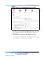
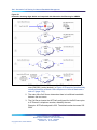
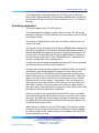
The following figure illustrates a typical network configuration that supports
dual homing of both the ELAN and TLAN. With this configuration, however,
a single Layer 2 switch remains a single point of failure.
Figure 6
Single server port network connections (dual-homing - non distributed)
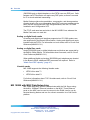
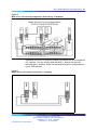
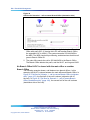
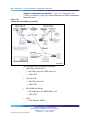
The following figure illustrates a typical network configuration that supports
dual homing of both the ELAN and TLAN. Multiple Layer 2 switches ensure
there isn’t a single point of failure. Nortel recommends this configuration for
the highest reliability in a single CPU Call Server configuration. You must
partition the layer 2 switch into separate VLANs to keep the ELAN and
TLAN traffic on separate subnets
Nortel Communication Server 1000
Branch Office Installation and Commissioning
NN43001-314 01.02 Standard
Release 5.0 20 June 2007
Copyright © 2007, Nortel Networks
.
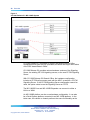
42 Overview
Figure 7
Single server port network connections (dual-homing - distributed)
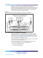
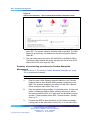
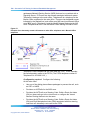
The following figure illustrates a typical network configuration for a dual
CPU Call Server configuration that supports dual homing of both the ELAN
and TLAN. Multiple Layer 2 switches ensure there isn’t a single point of
failure. Nortel recommends this configuration in a dual CPU Call Server
configuration. In this configuration, the CP-PM call server benefits from the
dual homing feature of the MGC, and remains connected to the network,
even if one of the layer 2 ELAN switches fails, avoiding a CPU switchover
due to a network outage.
Nortel Communication Server 1000
Branch Office Installation and Commissioning
NN43001-314 01.02 Standard
Release 5.0 20 June 2007
Copyright © 2007, Nortel Networks
.
MG 1000B with MGC Data Networking
43
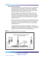
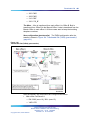
Figure 8
Multi server port network configuration (dual-homing - distributed)
Cascading can occur for the MGC network connections for up to a maximum
of 2 cabinets. You can directly cable the MGCs , without the need for
external Layer 2 switches. Nortel recommends this type of configuration for
a pure TDM solution.
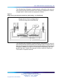
Figure 9
Single server port network connections - cascading
Nortel Communication Server 1000
Branch Office Installation and Commissioning
NN43001-314 01.02 Standard
Release 5.0 20 June 2007
Copyright © 2007, Nortel Networks
.
44 Overview
Multi Server (CP-P4) Port Network Configuration (Dual-homing Distributed), shows a configuration with a Call Server platform that does not
reside in a MG 1000B cabinet and chassis; therefore no direct connection
exists to the MGC. The CP-P4 call server does not use the MGC dual
homing feature to increase the system reliability
Figure 10
Multi server (CP-P4) port network configuration (dual-homing - distributed)
MG 1000B platform configuration overview
In each MG 1000B Core, one CP PM and MGC is required. The three
remaining slots (nine in an MG 1000B Cabinet) can contain analog line
cards, analog trunk cards, digital line cards, or digital trunk cards. Refer to
Table 3 "Card slots for MG 1000B Core and MG 1000B Expander" (page
32) for a summary of the allowable card slots.
Each MG 1000B Core with a digital trunk card must have a clock controller.
See Circuit Card Reference(NN43001-311)
For further information on line side T1 and line side E1 cards, refer to
There are two configurations for the MG 1000B platform:
•
without an MG 1000B Expander
•
with an MG 1000B Expander
Nortel Communication Server 1000
Branch Office Installation and Commissioning
NN43001-314 01.02 Standard
Release 5.0 20 June 2007
Copyright © 2007, Nortel Networks
.
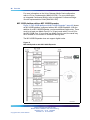
MG 1000B platform configuration overview
45
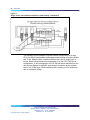
MG 1000B platform without an MG 1000B Expander
Figure 11 "MG 1000B platform without MG 1000B Expander" (page 45)
shows an MG 1000B platform configured without an MG 1000B Expander.
This configuration has a single MG 1000B Core.
Figure 11
MG 1000B platform without MG 1000B Expander
This MG 1000B platform configuration requires at least one Voice Gateway
Media Card. The additional slots can be used for any combination of the
following:
•
trunk card
•
analog or digital line card
•
second Media Card
•
Nortel Integrated Conference Bridge card
•
Nortel Integrated Recorded Announcer card
•
cards to support CallPilot Mini or CallPilot 201i
•
Meridian Mail card (for converted Small Systems only)
Nortel Communication Server 1000
Branch Office Installation and Commissioning
NN43001-314 01.02 Standard
Release 5.0 20 June 2007
Copyright © 2007, Nortel Networks
.
46 Overview
For more information on the Voice Gateway Media Card configuration,
refer to IP Line Fundamentals (NN43100-500). For more information
on Integrated Conference Bridge, refer to Integrated Conference Bridge
Service Implementation Guide (NN43001-558).
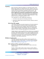
MG 1000B platform with an MG 1000B Expander
Figure 12 "MG 1000B platform with MG 1000B Expander" (page 46) shows
an MG 1000B platform configured with an MG 1000B Expander. With the
addition of an MG 1000B Expander, you have additional usable slots. There
must be at least one Media Card (8- or 32-port cards with IP Line 4.5) for
the MG 1000B Core. If more than one Media Card is used, the cards may
all be located in one chassis or distributed among them.
The MG 1000B Expander does not support digital trunks.
Figure 12
MG 1000B platform with MG 1000B Expander
Nortel Communication Server 1000
Branch Office Installation and Commissioning
NN43001-314 01.02 Standard
Release 5.0 20 June 2007
Copyright © 2007, Nortel Networks
.
Software requirements
47
Capacity
Each CS 1000 main office can support up to 255 branch offices. Each
Branch Office supports up to 400 IP Phone users. However, since all IP
Phones register with the main office, the governing factor is the maximum
number of IP Phones that can be supported at the main office. This
means the total number of IP Phones in all offices can be no greater
than the capacity of the main office, as determined using Communication
Server 1000E Planning and Engineering (NN43041-220), Communication
Server 1000M and Meridian 1 Large System Planning and Engineering
(NN43021-220), or Communication Server 1000M and Meridian 1 Small
System Planning and Engineering (NN43011-220).
The configuration of an MG 1000B platform depends on:
•
the number of line and trunk cards being provisioned
•
the number of Media Cards required to provide a sufficient number of
DSP channels
Media Card DSP capacity
The number of DSP ports to provision depends on the trunk-to-telephone
ratio. A rule-of-thumb is to have the number of ports greater than or
equal to the number of trunks configured. See Communication Server
1000S: Planning and Engineering (NN43031-220) (or Communication
Server 1000M and Meridian 1 Small System Planning and Engineering
(NN43011-220) for converted Small Systems) for more information.
If digital telephones and analog (500/2500-type) telephones are equipped at
the Branch Office, additional DSP ports are needed for digital-to-IP Phone
and analog-to-IP Phone connections. The number of additional DSP ports
must be equal to or greater than the expected number of simultaneous
connections of these types. The user can engineer fewer DSP ports
depending on their desired blocking ratio.
Software requirements
This section describes the relative software versions required in the
main office and Branch Office locations. The actual software packaging
requirements are given in "Main office requirements" (page 192) and
"Branch Office requirements" (page 193).
Main and Branch Office running the same release
Normally, the main office and associated Branch Office run the same
software release.
However, a Branch Office location can be running an earlier software
release than that running at the main office. This situation is discussed in
the next section.
Nortel Communication Server 1000
Branch Office Installation and Commissioning
NN43001-314 01.02 Standard
Release 5.0 20 June 2007
Copyright © 2007, Nortel Networks
.
48 Overview
Main and Branch Office running different releases
The Main Office Call Server and the Branch Office can have different
software releases, as long as the Main Office runs at the highest release.
With the introduction of CS 1000 Release 5.0 program, Nortel’s policy
will be if the main office Call Server is running CS 1000 Release 5.0, the
Branch Office can run on CS 1000 Release 5.0, CS 1000 Release 4.5, or
CS 1000 Release 4.0.
Some functionality found in CS 1000 Release 5.0 is not available in earlier
releases. For example, CS 1000 Release 4.0 does not support Active Call
Failover
It is recommended that the software release on the Branch Office always
match the software release on the main office. In addition, it is possible to
have branch offices running different software releases.
Take into consideration planning your upgrade with this mixed software
policy. Customers must ensure their Branch Offices are at CS 1000 Release
4.5 or CS 1000 Release 4.0 prior to upgrading the main office to CS 1000
Release 5.0 to ensure a supported configuration during the upgrade period.
Both the Call Server and Signaling Server in the main office must run the
same release of software.
If the NRS at the Branch Office is also the Alternate NRS in the network,
then both it and the Primary NRS must be running the same software
release.
This capability is required to support customers who are currently running a
network of CS 1000 Release 4.0 or CS 1000 Release 4.5 branch offices
with a CS 1000 Release 5.0 main office, and who want to add one Branch
Office running CS 1000 Release 5.0. By allowing this mixed-software
operation, customers do not have to upgrade their entire network from a
CS 1000 Release 4.0 or CS 1000 Release 4.5 to CS 1000 Release 5.0 at
the same time.
If the Branch Office is running CS 1000 Release 4.0 or CS 1000 Release
4.5, you do not have to upgrade the Branch Office to CS 1000 Release 5.0.
Indefinite operation with a mixed-software configuration of CS 1000 Release
4.0 and CS 1000 Release 4.5 branch offices and a CS 1000 Release 5.0
main office is supported.
For information on upgrading software, refer to "Upgrading to CS 1000
Release 5.0" (page 207).
Nortel Communication Server 1000
Branch Office Installation and Commissioning
NN43001-314 01.02 Standard
Release 5.0 20 June 2007
Copyright © 2007, Nortel Networks
.
Software requirements
49
Features in mixed-software configurations
Feature operation of IP Phone users in Normal Mode is the feature set on
the main office. IP Phone users in Local Mode use the feature set on the
Branch Office. Users of analog and digital devices always use the feature
set on the Branch Office.
However, be advised that if the Branch Office is running a lower release of
software than the main office, features involving interaction between the
main office and the Branch Office will not function for the Branch Office IP
Phone users. For example, if the main office is on CS 1000 Release 4.5 and
the Branch Office is on CS 1000 Release 4.0 or Succession 3.0, the Active
Call Failover feature and the Enhanced UNIStim Firmware download feature
will not operate for the Branch Office IP Phone users since these features
are not supported on earlier releases. In this case, the Branch Office would
need to be upgraded to CS 1000 Release 4.5 to support these features.
Adding a Branch Office to an existing network
For customers wanting to add a Branch Office to their existing network, with
the introduction of CS 1000 Release 5.0, customers are to order a Branch
Office running CS 1000 Release 4.0 if their main office is running CS 1000
Release 4.0. They are also permitted to order a Branch Office running
CS 1000 Release 4.5 if their main office is running CS 1000 Release 4.5.
However, they will no longer be permitted to order a Branch Office running
on Succession 3.0. This differs from the introduction of CS 1000 Release
4.5, customers which allowed customers to order a Branch Office running
Succession 3.0 software only if their main office is running Succession 3.0
software. They were also permitted to order a Branch Office running on
Succession 3.0 if the main office was running Succession 3.0.
IP Phone firmware
When you add a new CS 1000 Release 5.0 Branch Office to a network that
has CS 1000 Release 4.0 or CS 1000 Release 4.5 branch offices, you must
choose whether to upgrade IP Phone firmware for existing branch offices.
You can choose not to upgrade the IP Phone firmware at the existing branch
offices only if the IP Phones in those branch offices are running at least the
minimum version of firmware as specified in "Telephones" (page 36).
If you choose to upgrade only the IP Phone firmware, you must upgrade the
IP Phone firmware at the existing branch offices first. The main office may
not require an IP Phone firmware upgrade, depending on its current version.
With the introduction of Enhanced UNIStim Firmware Download feature
for Release 4.5, IP Phone firmware at the Branch Office is automatically
downloaded from the main office.
Nortel Communication Server 1000
Branch Office Installation and Commissioning
NN43001-314 01.02 Standard
Release 5.0 20 June 2007
Copyright © 2007, Nortel Networks
.
50 Overview
Refer to "Firmware downloads" (page 345) for more information on
upgrading firmware for the IP Phone 2001, IP Phone 2002, IP Phone 2004,
and IP Phone 2007.
Package Combinations
The MG 1000B with MGC requires existing packages 402 SOFTSWITCH
and 403 IPMG that were introduced in Rls 4.0.
Package combinations supported using the Rls 4.5 MG 1000B are
supported by the MG 1000B with MGC.
For MG 1000B with MGCs, the Branch Office package 390 and IPMG
package 403 are required.
GRPRIM (Geographic Redundancy Primary CS Package) and GRSEC
(Geographic Redundancy Secondary CS Package) are restricted on Branch
Office environment.
Supported applications
The Branch Office feature supports TM 3.01, Nortel Integrated Conference
Bridge, Nortel Integrated Recorded Announcer, CallPilot Mini, and CallPilot
201i at the Branch Office location.
Survivability
The Branch Office provides survivability against WAN failure, Main Office
Call Server failure, or Signaling Server failure. Survivability is also provided
during the Main Office upgrade, including Signaling Server and Call Server
upgrade. A Call Server and Signaling Server are required in the Branch
Office with CS 1000 Release 5.0.
The Branch Office supports Geographic Redundancy as a Main Office
feature. For further information on Geographic Redundancy, see System
Redundancy (NN43001-507).
Branch Office supports the Network Wide Redundancy Phase II feature,
which is supported by the MG 1000B to provide survivability to IP telephones
normally registered with a CS 2100 and CS 1000. For additional information
see theSystem Redundancy (NN43001-507)NTP.
If a LAN/WAN fails, the MG 1000B IP Phones lose communication with the
main office TPS. This causes the IP Phones to reset and register with the
MG 1000B TPS and the MG 1000B Call Server. The IP Phones operate in
Local Mode, and receive call processing services from the call server. In
Local Mode, the MG 1000B TPS tries to communicate with the main office
TPS at regular intervals. Once communication is established with the main
office TPS, the MG 1000B IP Phones are redirected to the main office.
Nortel Communication Server 1000
Branch Office Installation and Commissioning
NN43001-314 01.02 Standard
Release 5.0 20 June 2007
Copyright © 2007, Nortel Networks
.
Survivability
51
If the main office Call Server fails and call processing services are provided
by an alternate Call Server, the MG 1000B IP Phones register with the
alternate Call Server and receive call processing services from it. If no
alternate Call Server is available, the MG 1000B IP Phones stay registered
with the main office TPS for ten minutes. At the end of the ten minutes, the
IP Phones reset and register with the call server. If a key on a particular IP
Phone is pressed before the end of the ten minutes, that telephone resets
and registers with the call server immediately after the key is pressed.
When the main office Signaling Server fails and an Alternate Signaling
Server is available, the MG 1000B IP Phones reset and reregisters with the
main office Call Server through the Alternate Signaling Server, and continue
to receive call processing services from the main office Call Server. If no
Alternate Signaling Server is available, the MG 1000B IP Phones reset and
register with the call server. IP Phones that were registered with the call
server before the main office Signaling Server failure was detected are
then redirected back to the main office and register with the Voice Gateway
Media Card. These telephones stay in Normal Mode. IP Phones that
registered with the call server after the main office Signaling Server failure
was detected stay registered at the Branch Office.
If the Main Office has VTRK applications on the failed Signalling Server, the
NCS de-registers the Main Office from its database. Therefore, redirection
from local mode cannot be completed. If the alternative Signalling Server
has no TPS services configured (for example, it is purely an NRS, Personal
Directory (PD) Server, or pure VTRK), once again, redirection cannot be
completed. The correct scenario occurs when the NCS has a static endpoint
for the Main Office Node IP so there is no VTRK dependency. All TPSs
configured at the Main Office have the same H.323 ID. The Branch Office
maintains a connection to the NCS, or alternative NCS. In this particular
case, IP Phones are redirected to the Main Office even when a primary
Signalling Server fails.
When an MG 1000B IP Phone powers up, it registers first with the MG
1000B TPS, and second with the MG 1000B Call Server. It is then
redirected to the main office by the call server. The MG 1000B TPS queries
the Primary NCS for the main office node IP address to redirect the IP
Phone. The NCS provides the IP based on BUID value. If there are several
routes for a particular BUID route, the smaller route cost factor is chosen.
If the Primary NCS is down or unreachable, the MG 1000B TPS queries
the Alternate NCS. If the MG 1000B TPS receives a positive response,
the MG 1000B IP Phone is redirected to the main office. If the Alternate
NCS is also down or unreachable,the MG 1000B TPS queries the Failsafe
NRS. If a successful response is received from the Failsafe NRS, the IP
Phone registers with the main office. Otherwise, if neither an Alternate
NRS nor a Failsafe NRS is available, the MG 1000B IP Phone remains in
Nortel Communication Server 1000
Branch Office Installation and Commissioning
NN43001-314 01.02 Standard
Release 5.0 20 June 2007
Copyright © 2007, Nortel Networks
.
52 Overview
Local Mode at the Branch Office, the MG 1000B telephones remain in Local
Mode, displaying aServer Unreachable (1) message and receives all call
processing services from the CP PM in the MG 1000B Core.
MG 1000B IP Phones in Normal Mode remain registered with the main office
when the Primary NRS fails and no Alternate or Failsafe NRS is available.
They can call any main office telephone or IP Phones in Normal Mode in
other branch offices. However, they cannot call any MG 1000B digital
telephones, analog (500/2500-type) telephones, or any external number
through the MG 1000B trunks in the normal way, because the Virtual Trunks
are not available. (MG 1000B digital or analog (500/2500-type) telephones
are accessible if alternate routing is available through the PSTN.) The user
has the option of staying in Normal Mode, or going to Local Mode manually
by resetting the telephone or using Test Local Mode. In Local Mode, the
IP Phones can make local calls to other IP Phones, digital telephones, and
analog (500/2500-type) telephones at the Branch Office. They can also be
used to make outgoing PSTN calls as usual.
You must plan for, and obtain, the Primary and optional Alternate NRS
addresses for installing the Branch Office feature software. Determine the
NRS role, that is, the Alternate or Failsafe configuration, for the MG 1000B
Signaling Server.
Nortel recommends that the NRS in the MG 1000B be configured as a
Failsafe NRS, unless it is already acting as the Primary or Alternate NRS.
If the MG 1000B IP Phones go into Local Mode, they can use the MG
1000B NRS services.
For CallPilot Mini and CallPilot 201i applications, a Message Waiting
Indication (MWI) does not survive a Mode change (Normal to Local or Local
to Normal). The message itself is preserved, but the lamp indicator may not
be lit after the Mode change.
Active Call Failover
The Active Call Failover (ACF) feature for IP Phones allows active IP calls to
survive the following failures:
•
IP/IP calls and IP/TDM calls survive signaling path TLAN subnet failures.
•
IP and IP/TDM calls survive Signaling Server restarts.
•
IP and IP/TDM calls survive LTPS ELAN subnet failures.
•
IP calls survive a Call Server cold start and Call Server failures in
system configuration with a redundant Call Server.
ATTENTION
All IP Phones excluding Phase 1/0 support Active Call Failover.
Nortel Communication Server 1000
Branch Office Installation and Commissioning
NN43001-314 01.02 Standard
Release 5.0 20 June 2007
Copyright © 2007, Nortel Networks
.
Survivability
53
ACF mode
The ACF feature for IP Phones enables an IP Phone to reregister in the ACF
mode during a supported system failure.
The ACF mode preserves the following:
•
active media session
•
LED states of the Mute, Handsfree, and Headset keys
•
DRAM content
All other elements (the feature keys, soft keys and text areas) are retained
until the user presses a key or the connection with the Call Server is
resumed. If the user presses a key during the failover, the display area is
cleared and a localized "Server Unreachable" message is displayed.
The IP Phone uses this new mode of reregistration only when the Call Server
explicitly tells the IP Phone to do so. IP Phones clear all call information
when registering to a Call Server or LTPS that does not support the feature.
For further information on Active Call Failure, refer to IP Line Fundamentals
(NN43100-500).
Configuring S2 IP Address to point to the main office TPS
This configuration programs the S1 IP address parameter on the MG 1000B
IP Phone as the Node IP of the Branch Office, and S2 as the Node IP of the
main office (normally, S2 would be set to NULL).
This configuration provides better resiliency when an MG 1000B IP Phone
cannot access the Branch Office over the local LAN or WAN (due to network
problems, for example), but can access the main office. In this case, the IP
Phone tries to register directly with the main office.
This configuration is supported only under the following conditions:
•
Relaxed node ID checking is in operation between the Branch Office
and the main office. Four digits are configured on the TPS for the Node
ID, and the first three digits of that Node ID make up the Node ID on the
IP Phone. For example, 5701 is configured on the main office TPS and
5702 on the MG 1000B TPS, where 570 is the Node ID on the IP Phone.
•
The same TN is programmed on the main office and Branch Office for
the IP Phone.
•
The main office is a CS 1000E system.
The IP Softphone 2050 does not support S2 Addresses. However, the IP
Softphone 2050v2 does have the ability to configure S2.
Nortel Communication Server 1000
Branch Office Installation and Commissioning
NN43001-314 01.02 Standard
Release 5.0 20 June 2007
Copyright © 2007, Nortel Networks
.
54 Overview
For further information on this configuration and its limitations, see
"Configuring non-zero S2 IP Addresses" (page 169).
Nortel Communication Server 1000
Branch Office Installation and Commissioning
NN43001-314 01.02 Standard
Release 5.0 20 June 2007
Copyright © 2007, Nortel Networks
.
55
Bandwidth Management
Contents
This section contains information on the following topics:
"Introduction" (page 55)
"Codec negotiation" (page 56)
"Codec selection" (page 59)
"Codec selection algorithms" (page 59)
"Configuring Bandwidth Management parameters" (page 62)
"Zones" (page 62)
"Configuration rules" (page 62)
"Network Planning" (page 62)
"Enabling codecs" (page 63)
"Configuring Bandwidth Management" (page 64)
"Maintenance commands" (page 67)
"Adaptive Network Bandwidth Management" (page 70)
"Description" (page 70)
"Feature packaging" (page 76)
"Configuration rules" (page 77)
"Configuring Adaptive Network Bandwidth Management" (page 77)
"Maintenance commands" (page 84)
Introduction
CS 1000 supports Bandwidth Management on a network-wide basis so that
voice quality can be managed between multiple Call Servers.
Nortel Communication Server 1000
Branch Office Installation and Commissioning
NN43001-314 01.02 Standard
Release 5.0 20 June 2007
Copyright © 2007, Nortel Networks
.
56 Bandwidth Management
With the Network Bandwidth Management feature, you can configure
bandwidth zones on a network basis so that codec selection and bandwidth
allocation software can identify whether Internet Telephones or gateways
are physically co-located (in the same bandwidth zone) even though they
are controlled by different Call Servers.
Adaptive Network Bandwidth Management is an enhancement of Bandwidth
Management in which Quality of Service (QoS) metrics are used to
automatically lower available bandwidth.
ATTENTION
IMPORTANT!
After all bandwidth is used, any additional calls are blocked or rerouted. Keep this
in mind when designing and implementing Network Bandwidth Management.
Codec negotiation
Codec refers to the voice coding and compression algorithm used by DSPs.
Each codec has different QoS and compression properties.
IP Peer Networking supports the per-call selection of codec standards,
based on the type of call (interzone or intrazone). IP Peer Networking
supports the following codecs (with supported payload sizes in parentheses,
with the default value in bold):
•
G.711 A/mu-law (10 ms, 20 ms, and 30 ms)
•
G.729 A (10 ms, 20 ms, 30 ms, 40 ms, and 50 ms)
•
G.729 AB (10 ms, 20 ms, 30 ms, 40 ms, and 50 ms)
•
G.723.1 (30 ms) (though it can limit the number of DSP channels
available)
•
T.38 for fax
The G.XXX series of codecs are standards defined by the International
Telecommunications Union (ITU).
By default, the G.711 codec must be supported at both ends of a call.
Codec configuration is performed for each node and is independent of the
signaling gateway (SIP or H.323) that is used on the node.
If a CS1000E system is used, the same payload sizes for the same codec
type should be configured on all IPMG cabinets in a system. Otherwise,
TDM to TDM calls between IPMG cabinets are not successful.
If more than one codec is configured, then the minimum payload size among
the configured codecs is used for the SIP Trunk Gateway codec negotiation.
Nortel Communication Server 1000
Branch Office Installation and Commissioning
NN43001-314 01.02 Standard
Release 5.0 20 June 2007
Copyright © 2007, Nortel Networks
.
Codec negotiation 57
Nortel recommends configuring the same payload size for all codecs in
the same node.
SIP example
If a G.711 20ms codec and G.729 30ms codec are configured, then
codec negotiation uses the minimum payload size of 20 ms. That is, the
G.711 20ms codec and the G.729 20ms codec are used. Instead, Nortel
recommends that both G.711 and G.729 codecs be configured as 20ms.
When a G.729 30ms codec is configured, then the G.729 10ms/20ms/30ms
codecs are supported.
IP Peer Networking performs codec negotiation by providing a list of codecs
that the devices can support. Use CS 1000 Element Manager to configure
the list of codec capabilities. Refer to IP Peer Networking: Installation and
Configuration (NN43001-313) for instructions on configuring codecs.
The codec preference sequence sent over SIP/H.323 depends on the
bandwidth policy selected for the Virtual Trunk zone and the involved
telephones. For "Best Quality," the list is sorted from best to worst voice
quality. For "Best Bandwidth," the list is sorted from best to worst bandwidth
usage.
The G.711 codec delivers "toll quality" audio at 64 kbit/s. This codec is
optimal for speech quality, as it has the smallest delay and is resilient to
channel errors. However, the G.711 codec uses the largest bandwidth.
The G.729A codec provides near toll quality voice at a low delay. The
G.729A codec uses compression at 8 kbit/s. The G.729AB codec also
uses compression at 8 kbit/s.
The G.723.1 codec provides the greatest compression.
Payload default values need to be changed if the customer wants to
communicate with a third-party gateway that does not support the above
default payload sizes. Otherwise, IP Peer calls to or from the third-party
gateway are not successful.
If the payload sizes are set higher than the default values (for example,
to support a third-party gateway), then the local IP calls are affected by
higher latency. This is because the codec configuration applies to both IP
Peer calls and local IP (IP Line) calls.
Nortel Communication Server 1000
Branch Office Installation and Commissioning
NN43001-314 01.02 Standard
Release 5.0 20 June 2007
Copyright © 2007, Nortel Networks
.
58 Bandwidth Management
G.711 A-law and mu-law interworking
In case the far end uses a different Pulse Code Modulation (PCM) encoding
law for its G.711 codec, systems that are configured as G.711 A-law also
include G.711 mu-law on their codec preferences list. Systems configured
as G.711 mu-law include G.711 A-law as their last choice. Therefore,
encoding law conversion is performed between systems with different laws.
Bandwidth management and codecs
Bandwidth management defines which codecs are used for intrazone calls
and interzone calls.
Bandwidth management enables administrators to define codec preferences
for IP Phone to IP Phone calls controlled by the same CS 1000 system
within the same zone. These calls are known as intrazone calls. This is
different than the codec preferences for calls between an IP Phone on the
CS 1000 system to a Virtual Trunk (potentially an IP Phone on another
CS 1000 system) or calls to IP Phones in another zone. These calls are
known as interzone calls.
For example, you may prefer high quality speech (G.711) over high
bandwidth within one system, and lower quality speech (G.729AB) over
lower bandwidth to a Virtual Trunk. Such a mechanism can be useful when
a system is on the same LAN as the IP Phones it controls, but the other
systems are on a different LAN (connected through a WAN).
Virtual Trunks usage of bandwidth zones is different than IP Phone
bandwidth usage. For Virtual Trunks, a zone number is configured in the
Route Data Block (LD 16). The zone number determines codec selection
for interzone and intrazone calls (that is, Best Bandwidth or Best Quality).
Refer to IP Peer Networking: Installation and Configuration (NN43001-313)
for information on configuring the RDB zone.
Bandwidth usage for Virtual Trunks is accumulated in its zone to block
calls that exceed the bandwidth availability in a specific zone. However,
the amount of bandwidth that is required to complete a given call is not
known until both call endpoints have negotiated which codec to use.
The bandwidth used for calculating the usage of a Virtual Trunk call is
determined by the preferred codec of the device that connects to the Virtual
Trunk. If the device is an IP Phone, the bandwidth calculations use the
preferred codec of the IP Phone, based on the codec policy defined for
the zones involved (that is, Best Bandwidth or Best Quality). Likewise, the
bandwidth calculations use the preferred codec of the Voice Gateway Media
Card for connections between a circuit-switched device (for example, a PRI
trunk) and a Virtual Trunk.
Nortel Communication Server 1000
Branch Office Installation and Commissioning
NN43001-314 01.02 Standard
Release 5.0 20 June 2007
Copyright © 2007, Nortel Networks
.
Codec negotiation 59
Codec selection
For every Virtual Trunk call, a codec must be selected before the media
path can be opened. When a call is set up or modified (that is, media
redirection), one of two processes occurs:
•
The terminating node selects a common codec and sends the selected
codec to the originating node.
•
The codec selection occurs on both nodes.
Each node has two codec lists: its own list and the far end’s list. To select
the same codec on both nodes, it is essential to use the same codec
selection algorithm on both nodes. Before the codec selection occurs, the
following conditions are met:
•
Each codec list contains more than one payload size for a given codec
type (it depends on the codec configuration).
•
Each codec list is sorted by order of preference (the first codec in the
near end’s list is the near end’s most preferred codec, the first codec in
the far end’s list is the far end’s preferred codec).
Codec selection algorithms
When the codec lists meet the above conditions, one of the following codec
selection algorithms selects the codec to be used:
•
H.323 Master/Slave algorithm
•
SIP Offer/Answer model
•
"Best Bandwidth" codec selection algorithm
If a SIP trunk call is between a CS 1000 system and other third-party
gateway/SIP clients (for example, MCS 5100), then the codec selection
does not guarantee that the same codec is selected for a call from endpoint
A to endpoint B and for a call from endpoint B to endpoint A. This different
codec selection makes it difficult for bandwidth management. However, calls
between two CS 1000 systems have the same codec selection decision
regardless of who originated the call.
H.323 Master/Slave algorithm
In the case of a Virtual Trunk call between Nortel and third-party equipment,
the H.323 Master/Slave algorithm is used.
The codec selection algorithm proposed by the H.323 standard involves a
Master/Slave negotiation. This is initiated each time two nodes exchange
their capabilities (TCS message). The Master/Slave information decides
that one node is Master and the other node is Slave. The outcome of the
Master/Slave negotiation is not known in advance; it is a random result. One
node could be Master then Slave (or vice versa) during the same call.
Nortel Communication Server 1000
Branch Office Installation and Commissioning
NN43001-314 01.02 Standard
Release 5.0 20 June 2007
Copyright © 2007, Nortel Networks
.
60 Bandwidth Management
Algorithm details
following manner:
The H.323 Master/Slave algorithm operates in the
•
The Master node uses its own codec list as the preferred one and finds
a common codec in the far end’s list. In other words, the Master gets the
first codec in its list (for example, C1), checks in the far end’s list if it is a
common codec; if it is, C1 is the selected codec. Otherwise, it gets the
second codec in its list and verifies it against the far end, and so on.
•
The Slave node uses the far end’s list as the preferred one and finds
in its own list the common codec.
Issues caused by the H.323 Master/Slave algorithm The issues
caused by the Master/Slave algorithm are due to the random nature of the
Master/Slave information. In other words, one cannot predetermine the
codec that is used during a Virtual Trunk call.
The following are the issues associated with the H.323 Master/Slave
algorithm:
•
After an on-hold and off-hold scenario (which triggers Master/Slave
negotiation), the codec used for the restored call might be different than
the one used before on-hold, because the Master/Slave information
could have been changed.
•
When using "Fast Start" codec selection, a call from Telephone 1
(node1) to Telephone 2 (node2) can use a different codec than a
call from Telephone 2 (node2) to Telephone 1 (node1), because the
terminating end is always Master.
•
For tandem calls, the Master/Slave information is not relevant. The
Master/Slave information is designed for use between two nodes only,
not between three or more nodes. It makes the codec selection for
tandem calls more complex and inefficient.
To solve the issues, another codec selection algorithm, not based on the
unpredictable Master/Slave information, is needed. Since any change to the
Master/Slave algorithm implies a change to the H.323 standard, the new
codec algorithm is used for Virtual Trunk calls between Nortel equipment.
SIP Offer/Answer model
The SIP codec negotiation is based on the Offer/Answer model with Session
Description Protocol (SDP).
The following three cases of codec negotiation are supported:
•
The calling user agent sends an SDP offer with its codec list in the
INVITE message with a "sendrecv" attribute. In this case, the called
user agent selects one codec and sends the selected codec in an SDP
answer. The SDP answer is included in the 200 OK message (which is
the response to the INVITE) with the "sendrecv" attribute.
Nortel Communication Server 1000
Branch Office Installation and Commissioning
NN43001-314 01.02 Standard
Release 5.0 20 June 2007
Copyright © 2007, Nortel Networks
.
Codec negotiation 61
This is the preferred method of operation.
•
The calling user agent sends an SDP offer with its codec list in the
INVITE message with a "sendrecv" attribute. The called user agent
returns more than one codec in the SDP answer. In the case that many
codecs are included in the response, the calling user agent picks the
first compatible codec from the called user agent’s list, and sends a new
SDP offer with a single codec to lock it in.
•
If the SDP of the calling user agent is not present in the INVITE
message, then the called user agent sends its codec list in an SDP
offer in the 200 OK message, with the "sendrecv" attribute. The calling
user agent selects one codec and sends the selected codec in an SDP
answer inside the ACK message, with "sendrecv" attribute.
For more information on this algorithm, refer to RFC 3264 An Offer/Answer
Model with the Session Description Protocol (SDP).
Best Bandwidth codec selection algorithm
The "Best Bandwidth" codec selection algorithm solves the issues caused
by the H.323 Master/Slave algorithm. The "Best Bandwidth" algorithm
selects one common codec based on two codec lists. Every time the
selection is done with the same two lists, the selected codec is the same.
The "Best Bandwidth" codec decision is based on the codec type only,
it does not take into account the fact that some codecs, while generally
using less bandwidth, can consume more bandwidth than others at certain
payload sizes.
"Best Bandwidth" is also applicable to SIP.
Algorithm details The selected codec is the type considered as the
best bandwidth codec type. To know whether one codec type has better
bandwidth than another, see the rule as summarized in Table 5 "Best
Bandwidth algorithm - codec type" (page 61).
Table 5
Best Bandwidth algorithm - codec type
G.711 A law
G.711 mu-law
G.729 A
G. 729 AB
G. 723.1
G.711 A-law
G.711 A-law
G.711 mu-law
G.729 A
G. 729 AB
G. 723.1
G.711 mu-law
G.711 mu-law
G.711 mu-law
G.729 A
G. 729 AB
G. 723.1
G.729 A
G.729 A
G.729 A
G.729 A
G. 729 AB
G.729 A
G. 729 AB
G. 729 AB
G. 729 AB
G. 729 AB
G. 729 AB
G. 729 AB
G. 723.1
G. 723.1
G. 723.1
G.729 A
G. 729 AB
G. 723.1
Nortel Communication Server 1000
Branch Office Installation and Commissioning
NN43001-314 01.02 Standard
Release 5.0 20 June 2007
Copyright © 2007, Nortel Networks
.
62 Bandwidth Management
Configuring Bandwidth Management parameters
The following sections describe how to configure Bandwidth Management
in a CS 1000 network. Nortel recommends that you read the Bandwidth
Management section in Converging the Data Network with VoIP
(NN43001-260) before using the following configuration information.
Zones
Bandwidth Management Zones are configured for each endpoint on a Call
Server. The Network Bandwidth Zone number determines if a call is an
intrazone call or an interzone call. Once that is determined, the proper
codec and bandwidth limit is applied to the call.
All of the endpoints on one Call Server are configured with Zone number to
identify all of the endpoints as being in a unique geographic location in the
network. In addition, Virtual Trunks are configured with a Zone number that
is different from the endpoint Zone numbers in the Call Server.
Codec selection occurs as described in "Codec selection" (page 59).
Configuration rules
There are four configuration rules for Bandwidth Management, as follows:
1. Each Call Server in the network must be configured with a unique VPNI,
with the only exception noted in point 2, next.
2. Branch Office (MG 1000B and SRG) Call Servers must be configured
with the same VPNI as that of the main office Call Server with which
they register.
3. Nortel recommends that all the endpoints on a Call Server (IP Phones
and Voice Gateway Media Cards) be configured with the same Zone
number.
4. Virtual Trunks must be configured with a different Zone number than
the endpoints.
Network Planning
Before configuring Bandwidth Management in a CS1000 network, follow
these steps:
Step
Action
1
Choose unique VPNIs for all Call Servers in the network.
2
Choose unique Bandwidth Zone numbers for all Call Servers in
the network. These are used when configuring the endpoints
(telephones and gateways) on the Call Server.
Nortel Communication Server 1000
Branch Office Installation and Commissioning
NN43001-314 01.02 Standard
Release 5.0 20 June 2007
Copyright © 2007, Nortel Networks
.
Configuring Bandwidth Management parameters
63
3
Choose unique Bandwidth Zone numbers for the Virtual Trunks in
the network.
4
Choose the codecs that will be enabled on each Call Server.
5
Identify what the interzone codec strategy will be (BB-Best
Bandwidth or BQ-Best Quality) for each zone in the network.
6
Identify what the intrazone codec strategy will be (BB-Best
Bandwidth or BQ-Best Quality) for each zone in the network.
7
Calculate the bandwidth available for intrazone calls for each zone
in the network.
8
Calculate the bandwidth available for interzone calls for each zone
in the network.
9
Calculate the bandwidth available for intrazone calls
—End—
Enabling codecs
In Element Manager, select the codecs that will be enabled for calls on the
Call Server, and define the associated parameters, such as payload size.
Select the Nodes: Servers, Media Cards web page under IP Network.
Then click Edit on the Node Configuration web page, and click VGW and
IP phone codec profile. Select an existing codec or configure a new
one in the VGW and IP phone codec profile section, shown in Figure 13
"Configuring a codec" (page 64). Refer to IP Peer Networking: Installation
and Configuration (NN43001-313) for full instructions on configuring a
codec.
Nortel Communication Server 1000
Branch Office Installation and Commissioning
NN43001-314 01.02 Standard
Release 5.0 20 June 2007
Copyright © 2007, Nortel Networks
.
64 Bandwidth Management
Figure 13
Configuring a codec
Configuring Bandwidth Management
The steps to configure Bandwidth Management on the Call Server are as
follows:
Step
Action
1
Define a VPNI number in LD 15.
2
Configure the Bandwidth Management parameters for each zone on
the Call Server using either Element Manager (see "Configuration
using CS 1000 Element Manager" (page 65)) or LD 117 (see
"Configuration using LD 117" (page 66)):
•
Call Server zones that will be used for endpoints (telephones
and gateways) with the following properties:
— Intrazone Preferred Strategy = Best Quality (BQ)
— Intrazone Bandwidth = default (1000000)
— Interzone Preferred Strategy = Best Bandwidth (BB)
Nortel Communication Server 1000
Branch Office Installation and Commissioning
NN43001-314 01.02 Standard
Release 5.0 20 June 2007
Copyright © 2007, Nortel Networks
.
Configuring Bandwidth Management parameters
65
— Interzone Bandwidth = maximum bandwidth usage allowed
between peer Call Servers
•
Call Server zones that will be used for Virtual Trunks with the
following properties:
— Intrazone Preferred Strategy = Best Quality (BQ)
— Intrazone Bandwidth = default (1000000)
— Interzone Preferred Strategy = Best Bandwidth (BQ)
— Interzone Bandwidth = default (1000000)
3
Configure the IP Phone, DSP and Virtual Trunk data with the
corresponding zone numbers.
For example, for an IP Phone 2004 telephone in zone 8
LD 11
REQ NEW
TYPE 2004P1, 2004P2
...
ZONE 8
...
—End—
Configuration using CS 1000 Element Manager
Zones are configured from the Zones web page, shown in Figure 14 "Zones
web page" (page 66).
Refer to "Element Manager Branch Office zone configuration" (page 260) for
instructions on configuring a Network Bandwidth Management zone, using
the values given on "Configuring Bandwidth Management" (page 64).
Nortel Communication Server 1000
Branch Office Installation and Commissioning
NN43001-314 01.02 Standard
Release 5.0 20 June 2007
Copyright © 2007, Nortel Networks
.
66 Bandwidth Management
Figure 14
Zones web page
Configuration using LD 117
A new Bandwidth Management zone is configured in LD 117 using the
NEW ZONE command. An existing zone can be modified using the CHG
ZONE command.
LD 117 Configure a new or existing Bandwidth Management zone.
Command
Description
NEW | CHG ZONE <zoneNumber> [<intraZoneBandwidth> <intraZoneStrategy>
<interZoneBandwidth> <interZoneStrategy> <zoneIntent> <zoneResourceType>]
Configure a new zone (NEW) or change (CHG) an existing
zone, where:
•
zoneNumber = 0-255
•
intraZoneBandwidth = Available intrazone bandwidth
(Kbit/s); Nortel recommends this value be set to the
maximum value.
•
intraZoneStrategy = BB (Best Bandwidth) or BQ (Best
Quality); Nortel recommends this value be set to BQ.
•
interZoneBandwidth =
— For Call Server zone = Maximum bandwidth usage (in
Kbit/s) allowed between peer Call Servers
— For Virtual Trunk zones = 1000000 (Kbit/s)
Nortel Communication Server 1000
Branch Office Installation and Commissioning
NN43001-314 01.02 Standard
Release 5.0 20 June 2007
Copyright © 2007, Nortel Networks
.
Configuring Bandwidth Management parameters
67
Description
Command
•
interZoneStrategy = BB (Best Bandwidth) or BQ (Best
Quality); Nortel recommends this value be set to BB to
conserve interzone bandwidth.
•
zoneIntent = type of zone, where:
— MO = Main office (Call Server) zone
— BMG = Branch Media Gateway (for Branch Office
zones)
— VTRK = Virtual Trunk zone
•
zoneResourceType = resource intrazone preferred
strategy, where:
— shared = shared DSP channels (default)
— private = private DSP channels
In CS 1000 Release 4.5, the zones that were described with
BMG designator stay with BMG one, all the other zones
are provided with MO designator. It is possible to update
ZoneIntent using CHG ZONE command
Maintenance commands
Maintenance commands can be run from Element Manager or LD 117.
Maintenance using Element Manager
The PRT INTRAZONE and PRT INTERZONE commands are available in
Element Manager from the Zones web page, shown in Figure 14 "Zones web
page" (page 66). To access these commands, follow the steps in Procedure
1 "Printing intrazone and interzone statistics for a zone" (page 67).
Procedure 1
Printing intrazone and interzone statistics for a zone
Step
Action
1
Select IP Network > Zones from the navigator.
The Zones web page opens, as shown in Figure 14 "Zones web
page" (page 66).
2
Click Maintenance Commands for Zones (LD 117).
The Maintenance Commands for Zones web page opens, as
shown in Figure 15 "Maintenance Commands for Zones web page"
(page 68). This page lists all the configured zones.
Nortel Communication Server 1000
Branch Office Installation and Commissioning
NN43001-314 01.02 Standard
Release 5.0 20 June 2007
Copyright © 2007, Nortel Networks
.
68 Bandwidth Management
Figure 15
Maintenance Commands for Zones web page
3
Do one of the following:
•
To display intrazone statistics:
1. Select Print Interzone Statistics (PRT INTERZONE) from
the Action drop-down list.
2. Select a zone from the Zone Number drop-down list, by
doing of the following:
•
•
Select ALL to print statistics for all zones.
•
Select a specific zone number to display statistics for a
specific zone.
To display interzone statistics:
1. Select Print Intrazone Statistics per Local Zone (PRT
INTRAZONE) from the Action drop-down list.
2. Select a zone from the Near End Zone Number drop-down
list, by doing of the following:
4
•
Select ALL to print statistics for all zones.
•
Select a specific zone number to display statistics for a
specific zone.
Click Submit.
Nortel Communication Server 1000
Branch Office Installation and Commissioning
NN43001-314 01.02 Standard
Release 5.0 20 June 2007
Copyright © 2007, Nortel Networks
.
Configuring Bandwidth Management parameters
69
The Maintenance Commands for Zones web page reopens,
displaying the statistics for the specified zone or zones. A blank
field indicates that statistic is either not available or not applicable to
that zone.
Figure 16 "Element Manager - intrazone statistics" (page 69) shows
an example of intrazone statistics for a sample Zone 2.
Figure 16
Element Manager - intrazone statistics
—End—
Maintenance using LD 117
Use the PRT INTRAZONE or PRT INTERZONE commands in LD 117 to
view the intrazone or interzone statistics for specified zones.
ATTENTION
Do not use the PRT ZONE command it has been replaced by the PRT
INTRAZONE and PRT INTERZONE commands.
LD 117 Print zone statistics.
Command
Description
PRT INTRAZONE [<zone>]
Nortel Communication Server 1000
Branch Office Installation and Commissioning
NN43001-314 01.02 Standard
Release 5.0 20 June 2007
Copyright © 2007, Nortel Networks
.
70 Bandwidth Management
Description
Command
Print intrazone statistics for the identified zones, where:
•
zone = ALL or 0-255
The output of this command displays the following information:
•
Zone
•
Type = PRIVATE/SHARED
•
Strategy = BB/BQ
•
ZoneIntent = MO/BMG/VTRK
•
Bandwidth = number of Kbps
•
Usage = number of Kbps
•
Peak = %
PRT INTERZONE [<nearZone>] [<nearVPNI>] [<farZone>] [<farVPNI>]
Print interzone statistics for the specific VPNI zone; where:
•
nearZone = ALL or 0-255
The output of this command displays the following information:
•
Zone number = 0-255
•
Zone VPNI = 1-16283
•
Type= PRIVATE/SHARED
•
Strategy = BB/BQ
•
ZoneIntent = MO/VTRK
Adaptive Network Bandwidth Management
Description
The Adaptive Network Bandwidth Management feature enhances the
performance of Voice over Internet Protocol (VoIP) networks based
on real-time interaction. It provides the means to automatically adjust
bandwidth limits and take corrective action in response to Quality of Service
(QoS) feedback. This dynamic bandwidth adjustment maintains a high level
of voice quality during network degradation.
The Adaptive Network Bandwidth Management feature dynamically adapts
to QoS in the network and reduces the bandwidth available for interzone
calls if QoS degrades. Typically, each Call Server in the network has a zone
assigned to it. The Call Server keeps track of the bandwidth being used
between its own zone and zones belonging to other Call Servers. If the QoS
degrades between the Call Server’s zone and a particular zone belonging
Nortel Communication Server 1000
Branch Office Installation and Commissioning
NN43001-314 01.02 Standard
Release 5.0 20 June 2007
Copyright © 2007, Nortel Networks
.
Adaptive Network Bandwidth Management
71
to another Call Server, the available bandwidth is reduced automatically
between those two zones. When the QoS between the two zones improves,
then the bandwidth limit is allowed to return to normal.
When an IP Phone encounters degradation of the network, it informs the
Call Server through various QoS alarms. These QoS alarms (packet loss,
jitter, delay, and, for phase 2 IP Phones, R value) get reported to the Call
Server. Depending upon the rate of the incoming alarms and the value of
the alarms, the Call Server reduces the available bandwidth available to
make new calls. The Call Server will lower/limit the number of new calls
allowed, based on the available bandwidth. This prevents excessive calls
being placed on a network with limited bandwidth (resulting in poor voice
quality). Once the adjusted (lowered) bandwidth reaches its full capacity,
new calls are either routed to an alternate route (if available), using Network
Alternate Routing Service (NARS) or the Alternative Routing for NBWM
feature, or new calls are blocked. The Call Server continues to monitor the
network throughout the network degradation period. When the degradation
is removed or the performance of the network improves, the allowable
bandwidth returns to provisioned levels and the Call Server gradually starts
allowing new calls.
Essentially, Adaptive Network Bandwidth Management provides a fallback to
PSTN on QoS degradation for new calls. As a result, bandwidth is managed
and quality measured between all the zones across the entire network, and
when necessary corrective action is taken. Due to the real-time interaction
with the network, less maintenance is required for the network since the
system reacts automatically to network conditions.
With Adaptive Network Bandwidth Management, it is not necessary to
provision bandwidth parameters between every zone in the network. Rather,
the Call Server automatically learns of new zones in the network and applies
Adaptive Network Bandwidth Management to these new zones as required.
Therefore, as new Call Servers are added to the network, it is not necessary
to re-provision all the other Call Servers on the network to take into account
this new Call Server. Conversely, when Call Servers are removed from the
network, the remaining Call Servers age out the old Call Server information
and therefore, provide only up to date bandwidth information.
This feature operates between all IP Peer CS 1000 systems, including the
Media Gateway 1000B and Survivable Remote Gateway 50.
Nortel Communication Server 1000
Branch Office Installation and Commissioning
NN43001-314 01.02 Standard
Release 5.0 20 June 2007
Copyright © 2007, Nortel Networks
.
72 Bandwidth Management
Call scenario
A call is requested from a telephone in VPNI 1/Zone 2 on Call Server A to a
telephone in VPNI 3/Zone 3 on Call Server B. Both zones have Adaptive
Network Bandwidth Management enabled.
1. Call Server A contacts the Network Redirect Server to obtain the
address of Call Server B.
2. Call Server A sends a call setup message to Call Server B, identifying
the calling telephone’s VPNI and zone.
3. Call Server B determines if there is sufficient bandwidth for the call, and
sends back the VPNI and zone of the called telephone.
4. Call Server A checks its bandwidth table to determine if there is sufficient
bandwidth available for the call from Call Server A to Call Server B.
5. If Call Server A determines there is enough bandwidth available, the call
is established; otherwise, alternate treatment is provided in the form
of blocking or rerouting the call.
Both Call Server A and Call Server B must consult their own bandwidth
tables to determine if there is enough bandwidth for the call to proceed.
Figure 17 "Call Progress with Adaptive Network Bandwidth Management"
(page 73) shows this scenario.
Nortel Communication Server 1000
Branch Office Installation and Commissioning
NN43001-314 01.02 Standard
Release 5.0 20 June 2007
Copyright © 2007, Nortel Networks
.
Adaptive Network Bandwidth Management
73
Figure 17
Call Progress with Adaptive Network Bandwidth Management
Zone bandwidth management and Adaptive Network Bandwidth
Management
Using Element Manager or the Command Line Interface (CLI), previously
configured zones (except Zone 0) can have the Adaptive Network Bandwidth
Management feature turned on or off. Once turned on, alarm threshold
levels and the QoS coefficients can be adjusted from the default values.
Adaptive Network Bandwidth Management cannot be enabled for Zone 0.
When Adaptive Network Bandwidth Management is enabled for a particular
zone on the Call Server, the zone appears in the zone table. The zone table
can be displayed using Element Manager or LD 117. When a call is made
from the configured zone to another zone, the bandwidth used appears in
the zone table.
Nortel Communication Server 1000
Branch Office Installation and Commissioning
NN43001-314 01.02 Standard
Release 5.0 20 June 2007
Copyright © 2007, Nortel Networks
.
74 Bandwidth Management
When a call is made from a zone with Adaptive Network Bandwidth
Management enabled, to a third party gateway, which has no zone, then the
zone of the Virtual Trunk (VTRK) is used and appears in the zone table.
Figure 18 "Adaptive Network Bandwidth Management graph" (page 74)
shows an example of the bandwidth changes.
Figure 18
Adaptive Network Bandwidth Management graph
When a Call Server receives a QoS alarm, the two zones that originated
the alarm are determined. Using this information, the Call Server reduces
the bandwidth limit between the two zones. This zone-to-zone bandwidth
limit (in effect at any particular time) is known as the Sliding Maximum
Bandwidth Limit and is a percentage of the Configured Interzone bandwidth
limit. The Sliding Maximum value is displayed using the prt interzone
command. The QoS Factor % is also displayed and is the percentage of
the Sliding Maximum versus the configured allowable bandwidth. The Call
Server checks the Network Bandwidth zone management tables for the
originating and terminating zones of the new call to determine the available
bandwidth for the call.
For more information about alarms, refer to Software Input/Output: System
Messages (NN43001-712).
When feedback indicates a significant QoS change in a zone, the Call
Server reduces the available bandwidth (Sliding Maximum Bandwidth Limit)
in the zone until the QoS reaches a satisfactory level. Once satisfactory
QoS is reached, the bandwidth is slowly raised until either the full bandwidth
is available or until QoS degrades again. Bandwidth changes can be
configured to be gradual (to reduce rapid swings and variations) or rapid.
Nortel Communication Server 1000
Branch Office Installation and Commissioning
NN43001-314 01.02 Standard
Release 5.0 20 June 2007
Copyright © 2007, Nortel Networks
.
Adaptive Network Bandwidth Management
75
Multiple Appearance Directory Numbers (MADN) can exist on different
zones. Calls to an MADN are handled the same as other IP Phone calls,
and are subject to the same bandwidth limitations.
New SNMP alarms are provided to monitor the system. When the
bandwidth limit between zones is reduced below configured levels, an alarm
is raised. A Warning alarm and an Unacceptable alarm, each corresponding
to a drop below a configured threshold, are used. When the bandwidth
returns to normal, the alarm is cleared. If the bandwidth limit reaches
zero, an additional Unacceptable alarm is raised. These alarms allow the
system administrator to monitor the system and take corrective action
when required.
Adaptive Network Bandwidth Management configuration
parameters
Packet Loss (pl), Jitter (j) and Delay (d) measurements, along with the R
factor (r) in IP Phone 200x Phase II telephones, are used to calculate the
QoS level for the zones. The coefficients for these QoS measurements
packet loss (Cpl), jitter (Cj), delay (Cd), and the R factor (Cr) can be
configured and are used to calculate the rate of bandwidth change.
Increasing them from their default values causes the Sliding Maximum to
decrease faster in response to the specific QoS alarm.
The QoS Coefficient (CQoS) can be varied from its default value. Increasing
this value causes the Sliding Maximum to change more rapidly in response
to QoS alarms. However, making this value too large will result in loss
of overall bandwidth, as shown in Figure 19 "Effect of the default CQos
Coefficient" (page 75) below and Figure 20 "Effect of a higher CQoS
Coefficient" (page 76).
Figure 19
Effect of the default CQos Coefficient
Nortel Communication Server 1000
Branch Office Installation and Commissioning
NN43001-314 01.02 Standard
Release 5.0 20 June 2007
Copyright © 2007, Nortel Networks
.
76 Bandwidth Management
Figure 20
Effect of a higher CQoS Coefficient
Other configurable coefficients used in the calculation are the QoS
Coefficient (CQoS), QoS Response Time Increase (ZQRT), and QoS
Response Time Interval (ZQRTI). CQoS, Cr, Cd, Cpl, and Cj control the
rate of bandwidth decrease, while ZQRT and ZQRTI control the rate of
bandwidth increase.
The Call Admission Control (CAC) Validity Time Interval (CACVT) is used to
control the length of time that records from a Call Server are saved in the
Bandwidth Management table. If there have not been any calls between two
Call Servers within the configured time, the Call Server is removed from the
table. For example, if Call Server A has Call Server B in the table, and no
call has been placed between A and B for the CACVT time, then Call Server
A removes all Call Server B records in the table.
Limitations
Virtual Office IP Phones are not subject to bandwidth limitations. They
may not have the correct zone information configured. They can also be
controlled by a Call Server that is not responsible for the particular zone.
Thus, bandwidth management is not possible for these phones.
Feature packaging
The Adaptive Network Bandwidth Management feature requires the
following packages:
•
QoS Enhanced Reporting (PVQM) package 401
•
Call Admission Control (CAC) package 407
ATTENTION
Package 401, QoS Enhanced Reporting (PVQM), is required if the R value from
the Phase II IP Phones is to be reported and used in the calculations.
Nortel Communication Server 1000
Branch Office Installation and Commissioning
NN43001-314 01.02 Standard
Release 5.0 20 June 2007
Copyright © 2007, Nortel Networks
.
Adaptive Network Bandwidth Management
77
Configuration rules
The configuration rules for Adaptive Network Bandwidth Management are
as follows:
•
Each main office Call Server in a network must have a unique non-zero
VPNI.
•
All branch offices(MG1000B or SRG) associated with a particular main
office must have the same VPNI as the main office Call Server.
•
All IP Phones (other than specific IP SoftPhone 2050s) and DSP
endpoints on a Call Server must be configured for the same zone.
•
IP SoftPhone 2050s being used remotely must be configured for Zone 0.
•
Branch Office systems(MG 1000B or SRG) should tandem all calls
through the main office Call Server to allow bandwidth monitoring and
control. In this case, the media path is direct between the Branch Office
and any point in the network.
•
Trunk Route Optimization (TRO) must be disabled between the main
office Call Server and the MG 1000B Core or SRG. In this case, the
media path is direct between the Branch Office and any point in the
network.
•
Adaptive Network Bandwidth Management parameters are configured
on the main office only and must not be configured at the branch offices.
Configuring Adaptive Network Bandwidth Management
The following is a summary of the tasks necessary to configure Adaptive
Network Bandwidth Management in the network.
1. Enable the Call Admission Control (CAC) package.
2. Configure CAC in Element Manager or LD 117:
a. Configure the VPNI on the main office and branch offices.
b. Configure both the main office and Branch Office zones at the main
office.
c. Configure the Branch Office zone on the MG 1000B Core or SRG.
d. Configure the interzone and intrazone bandwidth limits at the main
office and MG 1000B Core or SRG.
e. Enable Adaptive Network Bandwidth Management for the zones
on the main office Call Server.
f.
If required, alter the Adaptive Network Bandwidth Management
parameters in keeping with the information in ""Advanced
Configuration Notes" (page 78)" below.
3. Tandem the outbound Branch Office calls by configuring the NRS.
Nortel Communication Server 1000
Branch Office Installation and Commissioning
NN43001-314 01.02 Standard
Release 5.0 20 June 2007
Copyright © 2007, Nortel Networks
.
78 Bandwidth Management
4. Tandem the inbound Branch Office calls by creating a dialing plan which
routes all calls destined for the Branch Office through the main office.
Advanced Configuration Notes
1. The default values for Cpl, Cj, Cd, Cr and CQos can be increased to
increase the response time for Sliding Maximum changes. However,
increasing them can cause the Sliding Maximum to temporarily decrease
to a lower value then necessary, resulting in the needless blocking of
interzone calls.
2. Increasing the value of ZQRT will increase the speed at which the
Sliding Maximum increases. The same effect can be achieved by
decreasing ZQRTI. However, changing these values can cause the
Sliding maximum to oscillate until the network degradation is removed.
Configuration using Element Manager
Element Manager can be used to enable and configure the feature.
The zone must exist before it can be configured for Adaptive Network
Bandwidth Management. Refer to IP Peer Networking: Installation and
Configuration (NN43001-313) for instruction on how to create and configure
basic properties of the zone.
To configure the Adaptive Network Bandwidth Management feature, select
a zone on the Zones web page (see Figure 14 "Zones web page" (page
66)) and click Adaptive Network Bandwidth Management and CAC. The
Adaptive Network Bandwidth Management and CAC web page opens,
as shown in Figure 21 "Adaptive Network Bandwidth Management and
CAC web page" (page 79).
ATTENTION
Do not configure Adaptive Networks Bandwidth Management for Zone 0 or Virtual
Trunk zones.
Nortel Communication Server 1000
Branch Office Installation and Commissioning
NN43001-314 01.02 Standard
Release 5.0 20 June 2007
Copyright © 2007, Nortel Networks
.
Adaptive Network Bandwidth Management
79
Figure 21
Adaptive Network Bandwidth Management and CAC web page
If the Adaptive Network Bandwidth Management feature is enabled using
the Enable Call Admission Control feature (ZCAC) check box, then the
other parameters can be adjusted as required.
Table 6 "Adaptive Network Bandwidth Management and CAC fields" (page
79) shows the fields in the Adaptive Network Bandwidth Management
and CAC web page, the field definitions, and their LD 117 command
equivalent.
Table 6
Adaptive Network Bandwidth Management and CAC fields
Field Title
Field Definition
LD 117
equivalents
Enable Call Admission
Control Feature (CAC)
Control the CAC feature for the zone
ENL ZCAC
•
Enable (check box selected)
•
disable (clear the check box)
Nortel Communication Server 1000
Branch Office Installation and Commissioning
NN43001-314 01.02 Standard
Release 5.0 20 June 2007
Copyright © 2007, Nortel Networks
.
DIS ZCAC
80 Bandwidth Management
LD 117
equivalents
Field Title
Field Definition
QoS Response Time
Increase (ZQRT)
Bandwidth limit increment, as a percentage of
the QoS factor for the zone
CHG ZQRT
QoS Response Time
Interval (ZQRTI)
Time (in minutes) between bandwidth limit
increments
CHG ZQRTI
Warning Alarm Threshold
(ZQWAT)
A QoS value, which is lower than this value, but
higher than the Critical (Unacceptable) Alarm
Threshold, triggers a Major Alarm.
CHG ZQWAT
Critical Alarm Threshold
(ZQUAT)
A QoS value, which is lower than this value,
triggers an Unacceptable (Critical) Alarm.
CHG ZQUAT
R Alarm Coefficient (CR)
The R (Cr) coefficient is used to calculate the
QoS value for the zone.
CHG CR
Packet Loss Alarm
Coefficient (CPL)
The Packet Loss (Cpl) coefficient is used to
calculate the QoS value for the zone.
CHG CPL
Delay Alarm Coefficient
(CD)
The Delay (Cd) coefficient is used to calculate
the QoS value for the zone.
CHG CD
Jitter Alarm Coefficient (CJ)
The Jitter (Cj) coefficient is used to calculate the
QoS value for the zone.
CHG CJ
Coefficient of QoS (CQoS)
The Coefficient of QoS (CQoS) is used to
calculate the overall QoS value for the zone.
CHG CQOS
Recent Validity Time
Interval (CACVT)
Amount of time (in hours) for zone-to-zone
record validity. Once this interval expires,
records for unused zones are purged from the
tables.
CHG CACVT
Configuration using Command Line Interface
You can also configure the Adaptive Network Bandwidth Management
feature using LD 117.
LD 117 - Configure Adaptive Network Bandwidth Management.
Command
Description
CHG CACVT <Zone> <Interval>
Configure the zone-to-zone record validity time interval, where:
•
Zone = 1-255
•
Interval = 1-(48)-255
CHG CD <Zone> <Cd>
Nortel Communication Server 1000
Branch Office Installation and Commissioning
NN43001-314 01.02 Standard
Release 5.0 20 June 2007
Copyright © 2007, Nortel Networks
.
Adaptive Network Bandwidth Management
Command
81
Description
Change the Cd coefficient in the formula that determines how quickly an alarm
reduces the Sliding Maximum bandwidth for the identified zone, where:
•
Zone = 1-255
•
Cd = Cd coefficient = 1-(50)-100
CHG CPL <Zone> <Cpl>
Change the Cpl coefficient in the formula that determines how quickly an alarm
reduces the Sliding Maximum bandwidth for the identified zone, where:
•
Zone = 1-255
•
Cpl = Cpl coefficient = 1-(50)-100
CHG CJ <Zone> <Jitter>
Change the Cj coefficient in the formula that determines how quickly an alarm
reduces the Sliding Maximum bandwidth for the identified zone, where:
•
Zone = 1-255
•
Jitter = Jitter coefficient = 1-(50)-100
CHG CQOS <Zone> <QoS>
Change the QoS coefficient in the formula that determines how quickly an
alarm reduces the Sliding Maximum bandwidth for the identified zone, where:
•
Zone = 1-255
•
QoS = QoS coefficient = 1-(50)-100
CHG CR <Zone> <Cr>
Change the Cr coefficient in the formula that determines how quickly an alarm
reduces the Sliding Maximum bandwidth for the identified zone, where:
•
Zone = 1-255
•
Cr = Cr coefficient = 1-(50)-100
CHG ZONE <zoneNumber> <intraZoneBandwidth> <intraZoneStrategy> <interZoneBandwidth>
<interZoneStrategy> [<zoneIntent> <zoneResourceType>]
Nortel Communication Server 1000
Branch Office Installation and Commissioning
NN43001-314 01.02 Standard
Release 5.0 20 June 2007
Copyright © 2007, Nortel Networks
.
82 Bandwidth Management
Command
Description
Change the parameters of an existing zone, where:
•
zoneNumber = 1-255
•
intraZoneBandwidth = 1000000 (Mbit/s)
•
intraZoneStrategy = intrazone preferred strategy
— Best Quality = BQ
— Best Bandwidth = BB
•
interZoneBandwidth = 1000000 (Mbit/s)
•
interZoneStrategy = intrazone preferred strategy
— Best Quality = BQ
— Best Bandwidth = BB
•
zoneIntent = type of zone, where:
— MO = Main office zone
— BMG = Branch Media Gateway (Branch Office) zone
— VTRK = Virtual Trunk zone
•
zoneResourceType = resource intrazone preferred strategy
— shared DSP channels (default) = shared
— private DSP channels = private
In CS 1000 Release 5.0, the zones that were described with BMG designator
stay with BMG one, all the other zones are provided with MO designator. It is
possible to update zoneIntent using the CHG ZONE command.
CHG ZQRT <Zone> <Incr>
Change ZQRT, which is Response time increase by percentage. It is used to
determine the increase to the Sliding Maximum for the identified zone, where:
•
Zone = 1-255
•
Incr = increase value in percentage = 1-(10)-100
CHG ZQRTI <Zone> <Interval>
Nortel Communication Server 1000
Branch Office Installation and Commissioning
NN43001-314 01.02 Standard
Release 5.0 20 June 2007
Copyright © 2007, Nortel Networks
.
Adaptive Network Bandwidth Management
Command
83
Description
Change the QoS Response Time Interval while alarms are not coming, to
increase the Sliding Maximum for the identified zone, where:
•
Zone = 1-255
•
Interval = interval in minutes = 1-(5)-120
CHG ZQUAT <Zone> <Thres>
Change the QoS Unacceptable Alarm Threshold value for the identified zone,
where:
•
Zone = 1-255
•
Thres = threshold value = 1-(75)-99
When the zone-to-zone QoS value drops below the threshold value, the alarm
is presented. This value must be below the value of ZQWAT.
CHG ZQWAT <Zone> <Thres>
Change the QoS Warning Alarm Threshold value for the identified zone, where:
•
Zone = 1-255
•
Thres = threshold value = 1-(85)-99
When the zone-to-zone QoS value drops below the threshold value, the alarm
is presented. The value for ZQWAT must be higher than the value of ZQUAT.
NEW ZONE <zoneNumber> [<intraZoneBandwidth> <intraZoneStrategy> <interZoneBandwidth>
<interZoneStrategy> <zoneIntent> <zoneResourceType>]
•
zoneNumber = 1-255
•
intraZoneBandwidth = 1000000 (Mbit/s)
•
intraZoneStrategy = BQ (Best Quality)
•
interZoneBandwidth = 1000000 (Mbit/s)
•
interZoneStrategy = intrazone preferred strategy
— Best Quality = BQ
— Best Bandwidth = BB
•
zoneIntent = type of zone, where:
— MO = Main office zone
Nortel Communication Server 1000
Branch Office Installation and Commissioning
NN43001-314 01.02 Standard
Release 5.0 20 June 2007
Copyright © 2007, Nortel Networks
.
84 Bandwidth Management
Description
Command
— BMG = Branch Media Gateway (Branch Office) zone
— VTRK = Virtual Trunk zone
•
zoneResourceType = resource intrazone preferred strategy
— shared DSP channels (default) = shared
— private DSP channels = private
DIS ZCAC <Zone>
Disables the Call Admission Control (CAC) feature for the specified zone,
where:
•
Zone = 1-255
Disables the feature on a zone-by-zone basis.
ENL ZCAC <Zone>
Enables the Call Admission Control (CAC) feature for the specified zone,
where:
•
Zone = 1-255
Enables the feature on a zone-by-zone basis.
Maintenance commands
The Adaptive Network Bandwidth Management feature can be maintained
using Element Manager or LD 117.
Maintenance using Element Manager
The CAC parameters, intrazone statistics, and interzone statistics for one of
more zones are available in Element Manager from the Zones web page,
shown in Figure 14 "Zones web page" (page 66). To view the intrazone
or interzone statistics, use Procedure 1 "Printing intrazone and interzone
statistics for a zone" (page 67). To display the CAC parameters, follow the
steps in Procedure 2 "Displaying CAC parameters for one or more zones"
(page 85).
Nortel Communication Server 1000
Branch Office Installation and Commissioning
NN43001-314 01.02 Standard
Release 5.0 20 June 2007
Copyright © 2007, Nortel Networks
.
Adaptive Network Bandwidth Management
85
Procedure 2
Displaying CAC parameters for one or more zones
Step
Action
1
Select IP Network > Zones from the navigator.
The Zones web page opens (see Figure 14 "Zones web page"
(page 66)).
2
Click Maintenance Commands for Zones (LD 117).
The Maintenance Commands for Zones web page opens, as
shown in Figure 15 "Maintenance Commands for Zones web
page" (page 68). This page lists all the configured zones and their
intrazone statistics by default.
3
Select Print Adaptive Network Bandwidth Management and CAC
Parameters (PRT ZCAC) from the Action drop-down list.
4
Select a zone from the Zone Number drop-down list, by doing one
of the following:
5
•
Select ALL to print statistics for all zones.
•
Select a specific zone number to display statistics for a specific
zone.
Click Submit.
The Maintenance Commands for Zones web page reopens,
displaying the statistics for the specified zone or zones. A blank
field indicates that statistic is either not available or not applicable to
that zone.
Figure 22 "Element Manager - CAC parameters" (page 86) shows
an example of the CAC parameters for all Zones.
—End—
Nortel Communication Server 1000
Branch Office Installation and Commissioning
NN43001-314 01.02 Standard
Release 5.0 20 June 2007
Copyright © 2007, Nortel Networks
.
86 Bandwidth Management
Figure 22
Element Manager - CAC parameters
Maintenance using LD 117
The same information can be displayed using commands in LD 117.
LD 117 - Display Adaptive Network Bandwidth Management information
Command
Description
CLR CACR <nearZone> [<nearVPNI>] [<farZone>] [<farVPNI>]
Clear zone-to-zone record for near (VPNI-Zone) for far (VPNI-Zone), where:
•
nearZone = 0-255
•
nearVPNI = 1-16383
•
farZone = 0-255
•
farVPNI = 1-16383
PRT INTRAZONE [<zone>]
Nortel Communication Server 1000
Branch Office Installation and Commissioning
NN43001-314 01.02 Standard
Release 5.0 20 June 2007
Copyright © 2007, Nortel Networks
.
Adaptive Network Bandwidth Management
Command
Description
Print intrazone statistics for the identified zones, where:
•
zone = ALL or 1-255
The output of this command displays the following information:
•
Zone
•
State = ENL/DIS
•
Type = PRIVATE/SHARED
•
Strategy = BB/BQ
•
MO/VTRK/BMG = zoneIntent
•
Bandwidth = Kbps
•
Usage = Kbps
•
Peak = %
Figure 23 "Sample output for PRT INTRAZONE command" (page 89) shows
an example of the output for this command.
PRT INTERZONE [<nearZone>] [<nearVPNI>] [<farZone>] [<farVPNI>]
Print interzone statistics for the specific VPNI zone; where:
•
nearZone = ALL or 1-255
•
nearVPNI = 1-16383
•
farZone = 0-255
•
farVPNI = 1-16383
The output of this command displays the following information:
•
Near end Zone
•
Near end VPNI
•
Far end Zone
•
Far end VPNI
•
State = ENL/DIS
•
Type = PRIVATE/SHARED
Nortel Communication Server 1000
Branch Office Installation and Commissioning
NN43001-314 01.02 Standard
Release 5.0 20 June 2007
Copyright © 2007, Nortel Networks
.
87
88 Bandwidth Management
Command
Description
•
Strategy = BB/BQ
•
MO/VTRK /BMG= zoneIntent
•
QoS factor = %
•
Bandwidth configured = Kbps
•
Sliding max = Kbps
•
Usage = Kbps
•
Peak = %
•
Call = Cph
•
Alarm = Aph
The report rows are grouped as:
•
First row = summary bandwidth usage per near zone
•
Next rows = bandwidth usage per near (VPNI- Zone) and far (VPNI - Zone)
Figure 24 "Sample output for PRT INTERZONE command" (page 90) shows
an example of the output for this command.
PRT ZCAC [<zone>]
Print CAC parameters for the specified zone, or for all zones, where:
•
zone = ALL or 1-255
The output of this command displays the following information:
•
Local ZONE = 1-255
•
State = ENL/DIS
•
CR = 1-100
•
CPL = 1-100
•
CD = 1-100
•
CJ = 1-100
•
CQOS = 1-100
•
ZQRT = 1-100
Nortel Communication Server 1000
Branch Office Installation and Commissioning
NN43001-314 01.02 Standard
Release 5.0 20 June 2007
Copyright © 2007, Nortel Networks
.
Adaptive Network Bandwidth Management
Command
89
Description
•
ZQRTI = 10-120
•
ZQUAT = 1-99
•
ZQWAT =1-99
•
CACVT = 1-255
Sample outputs for PRT commands Figure 23 "Sample output for
PRT INTRAZONE command" (page 89) shows an example of the output
of the PRT INTRAZONE command. Figure 24 "Sample output for PRT
INTERZONE command" (page 90) shows an example of the output of the
PRT INTERZONE command.
Figure 23
Sample output for PRT INTRAZONE command
Nortel Communication Server 1000
Branch Office Installation and Commissioning
NN43001-314 01.02 Standard
Release 5.0 20 June 2007
Copyright © 2007, Nortel Networks
.
90 Bandwidth Management
Figure 24
Sample output for PRT INTERZONE command
Tandem Bandwidth Management overview
In order for the main office to correctly keep track of all the bandwidth being
used to and from a Branch Office the call must be tandemed through the
main office. When calls are tandemed through the main office only the
signaling is tandemed, the actual voice bandwidth travels directly between
the source and destination.
Nortel Communication Server 1000
Branch Office Installation and Commissioning
NN43001-314 01.02 Standard
Release 5.0 20 June 2007
Copyright © 2007, Nortel Networks
.
Dialing Plan Overview
91
Bandwidth utilization for the Branch Office is tracked at the main office and
can be displayed in LD 117 using the PRT INTERZONE command. To
provide the correct bandwidth utilization to the main office Call Server,
when a Branch Office is calling another node in the network, the calls must
be tandemed through the main office Call Server in both the inbound and
outbound direction.
Entering the main office Gateway endpoint identifier in the Tandem Endpoint
field for each Branch Office gateways configured on the NRS only provides
tandeming in the outbound direction from each Branch Office (from Branch
Office to main office).
To tandem calls through the main office in the inbound direction (from main
office to Branch Office), one must make use of the dialing plan capabilities
of the CS 1000 to first route the call to the main office. The main office
prepends a prefix to the dialed number and the number is routed to the
Branch Office.
Tandeming all Branch Office calls through the main office allows the main
office to keep track of the bandwidth being used at each Branch Office.
Application
This feature applies to the Branch Office and the Adaptive Bandwidth
Management feature. Specifically, it applies to calls made to and from the
Branch Office from either telephones registered locally at the Branch Office
(digital, analog [500/2500-type], and IP Phones) or trunks at the Branch
Office to another node in the network. It does not apply when using Branch
Office IP Phones that are registered with the main office (for example,
Normal Mode).
Dialing Plan Overview
Depending upon the type of dialing plan used in the network (Coordinated
Dialing Plan [CDP], or Uniform Dialing Plan [UDP] or a combination of both)
the general idea is to have all calls that are terminating at a Branch Office
first dial a number that will get routed to the main office associated with that
Branch Office. The main office recognizes this number as belonging to
the Branch Office and appends a tandem prefix to this number using Digit
Manipulation Index (DMI). The main office then routes the call to the Branch
Office while accounting for the additional bandwidth used.
See Figure 25 "A call between two branch offices tandems through the main
office" (page 92) for an example of a tandem call.
Nortel Communication Server 1000
Branch Office Installation and Commissioning
NN43001-314 01.02 Standard
Release 5.0 20 June 2007
Copyright © 2007, Nortel Networks
.
92 Bandwidth Management
Figure 25
A call between two branch offices tandems through the main office
Figure 26 "General legend" (page 93) on Figure 26 "General legend" (page
93) shows a general legend for the figures in the following section.
Nortel Communication Server 1000
Branch Office Installation and Commissioning
NN43001-314 01.02 Standard
Release 5.0 20 June 2007
Copyright © 2007, Nortel Networks
.
Network using Uniform Dialing Plan 93
Figure 26
General legend
Network using Uniform Dialing Plan
The following section provides general network configuration for a network
using UDP only.
Nortel Communication Server 1000
Branch Office Installation and Commissioning
NN43001-314 01.02 Standard
Release 5.0 20 June 2007
Copyright © 2007, Nortel Networks
.
94 Bandwidth Management
Figure 27 "Scenario 1: UDP throughout the network" (page 94) shows two
or more main offices with their branch offices, within a larger network.
Callers within each main office/Branch Office "region" use UDP to place
calls between systems. Callers also use UDP to place calls across the IP
network to the other main office(s) and its (their) branch offices.
In a typical network, a full region uses a single Home Location Code
(HLOC). However, it is also possible, where the number of users requires it,
to have two or more codes, although using one for the main office and one
for each Branch Office is unlikely at best.
Figure 27
Scenario 1: UDP throughout the network
Common details
In general, if an HLOC is shared between two or more systems, the
provisioning at the main office gets more complex, unless all branch offices
share HLOCs with the main office. That is, if the main office has two or more
HLOCs, and one or more of these (but not necessarily the same one) is
used by every Branch Office, then provisioning is relatively straight forward.
Nortel Communication Server 1000
Branch Office Installation and Commissioning
NN43001-314 01.02 Standard
Release 5.0 20 June 2007
Copyright © 2007, Nortel Networks
.
Network using Uniform Dialing Plan 95
Table 7 "Configuration details for the general case" (page 95) describes the
network configuration and the steps that a call takes during its setup.
Table 7
Configuration details for the general case
Call progress
steps
Region
Configuration detail and call progress
during call setup
1, 2, 3
UDP used for all calls within the region.
1, 2, 3
UDP used for region to region calls.
1, 2, 3
Prefixes for branch offices for regular calls are
required for all branch offices. May have additional
prefixes for E-911 calls, if required, or may share
prefixes.
1
1
All branch offices are provisioned at the NRS to route
all outbound calls (from the Branch Office) through
the main office. (NRS tandem configuration).
1
2
Main office sends all UDP calls to destinations
that are not its own Branch Office to the NRS with
unchanged dialled digits.
1
3
Main office sends all UDP calls to destinations that
are its own Branch Office to the NRS with a specific
gateway prefix in front of the dialled digits.
1
4
All branch offices delete the prefix and any LOC
codes, and terminate the calls. May be to a local set
or to a trunk.
2,3
Similar call setup steps take places for calls within
region 2 and 3.
Differences when every Branch Office HLOC is shared with the main
office
Table 8 "Provisioning details for this case" (page 95) shows the configuration
when the Branch Office HLOC is shared with the main office.
Table 8
Provisioning details for this case
Region
Provisioning detail
1
Provisioning on the main office requires parsing to only "normal"
LOC identification and HLOC deletion.
1
LOC values that are on branch offices may be provisioned as
extended LOCs (> 3 digit codes).
Nortel Communication Server 1000
Branch Office Installation and Commissioning
NN43001-314 01.02 Standard
Release 5.0 20 June 2007
Copyright © 2007, Nortel Networks
.
96 Bandwidth Management
Region
Provisioning detail
1
The DMI for the Branch Office "LOC" inserts a gateway routing
prefix in front of the number.
2,3
Similar configuration, as above, applies to regions 2 and 3.
Call between two branch offices associated with the same main office
The following scenarios describe calls between two branch offices that
belong to the same main office. the different scenarios described below
vary vary in the manner in which the HLOC is architected; branch offices
have same HLOC as the main office, branch offices have a different HLOC
than the main office and so on.
Every Branch Office HLOC is shared with the main office
In the following example, the HLOC of all the branch offices and the HLOC
of the main office are all the same. See Figure 28 "Call flow for Scenario 1 local call" (page 96).
Figure 28
Call flow for Scenario 1 - local call
1. The Branch Office user dials 6-395-3456. The system transmits
395-3456 to the NRS. The NRS checks its provisioning, and determines
that all calls are to be sent to the main office; it directs the call to the
main office.
Nortel Communication Server 1000
Branch Office Installation and Commissioning
NN43001-314 01.02 Standard
Release 5.0 20 June 2007
Copyright © 2007, Nortel Networks
.
Network using Uniform Dialing Plan 97
2. The Branch Office sends the call to 395-3456 to the main office.
3. The main office determines that this is LOC 39534, to another Branch
Office, with gateway routing prefix 552. The system inserts the
prefix and transmits 552-395-3456 to the NRS. The NRS checks its
provisioning, and determines that all calls to prefix 552 are to be sent to
Branch Office A2; it directs the call to the Branch Office.
4. The main office sends the call to 552-395-3456 to the Branch Office.
The Branch Office deletes the prefix and the HLOC, and rings set 3456.
No Branch Office HLOC is shared with the main office, but can be
shared with another Branch Office
In this example, the HLOC of the branch offices are the same but the HLOC
of the main office is different. See Figure 29 "Call flow for Scenario 1 local call" (page 97).
Figure 29
Call flow for Scenario 1 - local call
1. The Branch Office user dials 6-395-3456. The system transmits
395-3456 to the NRS. The NRS checks its provisioning, and determines
that all calls are to be sent to the main office; it directs the call to the
main office.
2. The Branch Office sends the call to 395-3456 to the main office.
Nortel Communication Server 1000
Branch Office Installation and Commissioning
NN43001-314 01.02 Standard
Release 5.0 20 June 2007
Copyright © 2007, Nortel Networks
.
98 Bandwidth Management
3. The main office determines that this is LOC 39534 to another Branch
Office, with gateway routing prefix 552. The system inserts the
prefix and transmits 552-395-3456 to the NRS. The NRS checks its
provisioning, and determines that all calls to prefix 552 are to be sent to
Branch Office A2; it directs the call to the Branch Office.
4. The main office sends the call to 552-395-3456 to the Branch Office.
The Branch Office deletes the prefix and the HLOC and rings set 3456.
No Branch Office HLOC is shared with the main office or another
Branch Office
In this example, the HLOC is unique between all the branch offices and the
main office. See Figure 30 "Call flow for Scenario 1- local call" (page 98).
Figure 30
Call flow for Scenario 1- local call
1. The Branch Office user dials 6-395-3456. The system transmits
399-3456 to the Branch Office user dials 6-399-3456. NRS. The NRS
checks its provisioning, and determines that all calls are to be sent to
the main office; it directs the call to the main office.
2. The Branch Office sends the call to 399-3456 to the main office.
3. The main office determines that this is to another Branch Office,
with office prefix 552. The system inserts the prefix and transmits
552-399-3456 to the NRS. The NRS checks its provisioning, and
Nortel Communication Server 1000
Branch Office Installation and Commissioning
NN43001-314 01.02 Standard
Release 5.0 20 June 2007
Copyright © 2007, Nortel Networks
.
Network using Uniform Dialing Plan 99
determines that all calls to prefix 552 are to be sent to Branch Office A2;
it directs the call to the Branch Office.
4. The main office sends the call to 552-399-3456 to the Branch Office.
The Branch Office deletes the prefix and the HLOC, and rings set 3456.
Call between branch offices associated with different main office
The following scenarios describe calls between two branch offices that
belong to different main offices. Note that the different scenarios described
below vary in the manner in which the HLOC is architected; branch offices
have same HLOC as the main office, branch offices have a different HLOC
than the main office and so on.
Every Branch Office HLOC is shared with the main office
In Figure 31 "Call flow for Scenario 1 - call to a remote Branch Office
(originator side)" (page 99), the first half of the call setup is shown (the
originator side is side A). In this example, the Branch Office and the main
office share the same HLOC. In Figure 32 "Call flow for Scenario 1 - call
to remote Branch Office (destination side)" (page 100), the second half of
the call is shown (the terminating side is side B).
Figure 31
Call flow for Scenario 1 - call to a remote Branch Office (originator side)
1. The Branch Office user dials 6-444-3456. The system transmits
444-3456 to the NRS. The NRS checks its provisioning, and determines
Nortel Communication Server 1000
Branch Office Installation and Commissioning
NN43001-314 01.02 Standard
Release 5.0 20 June 2007
Copyright © 2007, Nortel Networks
.
100 Bandwidth Management
that all calls are to be sent to the main office; it directs the call to the
main office.
2. The Branch Office sends the call to 444-3456 to the main office.
3. The main office determines that this is to another main office. The
system transmits 444-3456 to the NRS. The NRS checks its provisioning,
and determines that this call goes to main office B.
Figure 32
Call flow for Scenario 1 - call to remote Branch Office (destination side)
1. Main office B determines that this is to LOC 44434, which is a local
Branch Office with prefix 225. The system transmits 225-444-3456 to
the NRS. The NRS checks its provisioning, and determines that this call
goes to Branch Office B1.
2. The main office sends the call to 225-444-3456 to the Branch Office.
The Branch Office deletes the prefix, discovers the call is to its HLOC
444, deletes the HLOC, and rings set 3456.
No Branch Office HLOC is shared with the main office, but can
be shared with another Branch Office
In Figure 33 "Call flow for Scenario 1 - call to remote Branch Office
(originator side)" (page 101), the first half of the call is shown (originator
side of the call). In Figure 34 "Call flow for Scenario 1 - call to remote
Branch Office (destination side)" (page 102), the second half of the call is
shown (destination side of the call).
Nortel Communication Server 1000
Branch Office Installation and Commissioning
NN43001-314 01.02 Standard
Release 5.0 20 June 2007
Copyright © 2007, Nortel Networks
.
Network using Uniform Dialing Plan 101
Figure 33
Call flow for Scenario 1 - call to remote Branch Office (originator side)
1. The Branch Office user dials 6-444-3456. The system transmits
444-3456 to the NRS. The NRS checks its provisioning, and determines
that all calls are to be sent to the main office; it directs the call to the
main office.
2. The Branch Office sends the call to 444-3456 to the main office.
3. The main office determines that this is to another main office. The
system transmits 444-3456 to the NRS. The NRS checks its provisioning,
and determines that this call goes to main office B.
Nortel Communication Server 1000
Branch Office Installation and Commissioning
NN43001-314 01.02 Standard
Release 5.0 20 June 2007
Copyright © 2007, Nortel Networks
.
102 Bandwidth Management
Figure 34
Call flow for Scenario 1 - call to remote Branch Office (destination side)
1. Main office B determines that this LOC plus digits is to a local Branch
Office with prefix 225. (If sharing this LOC with another Branch Office,
the extended LOC is 44434.) The system transmits 225-444-3456 to
the NRS. The NRS checks its provisioning, and determines that this call
goes to Branch Office B1.
2. The main office sends the call to 225-444-3456 to the Branch Office.
The Branch Office deletes the prefix, and the HLOC, and rings set 3456.
No Branch Office HLOC is shared with the main office or another
Branch Office
The following example shows a call between two branch offices. In this
example, the HLOC is unique between the main office and Branch Office. In
Figure 35 "Call flow for Scenario 1 - call to remote Branch Office (originator
side)" (page 103), the first half of the call is shown (originator side of
the call). In Figure 36 "Call flow for Scenario 1 - call to remote Branch
Office (destination side)" (page 104), the second half of the call is shown
(destination side of the call).
Nortel Communication Server 1000
Branch Office Installation and Commissioning
NN43001-314 01.02 Standard
Release 5.0 20 June 2007
Copyright © 2007, Nortel Networks
.
Network using Uniform Dialing Plan 103
Figure 35
Call flow for Scenario 1 - call to remote Branch Office (originator side)
1. The Branch Office user dials 6-444-3456. The system transmits
444-3456 to the NRS. The NRS checks its provisioning, and determines
that all calls are to be sent to the main office; it directs the call to the
main office.
2. The Branch Office sends the call to 444-3456 to the main office.
3. The main office determines that this is to another main office. The
system transmits 444-3456 to the NRS. NRS checks its provisioning,
and determines that this call goes to main office B.
Nortel Communication Server 1000
Branch Office Installation and Commissioning
NN43001-314 01.02 Standard
Release 5.0 20 June 2007
Copyright © 2007, Nortel Networks
.
104 Bandwidth Management
Figure 36
Call flow for Scenario 1 - call to remote Branch Office (destination side)
1. Main office B determines that LOC 444 is to a local Branch Office with
prefix 225. The system transmits 225-444-3456 to the NRS. The NRS
checks its provisioning, and determines that this call goes to Branch
Office B1.
2. The main office sends the call to 225-444-3456 to the Branch Office.
The Branch Office deletes the prefix, discovers the call is to its HLOC,
deletes the HLOC, and rings set 3456.
Summary of provisioning procedures for Tandem Bandwidth
Management
Use Procedure 3 "Provisioning Tandem Bandwidth Management" (page
106) to provision the network.
Step
Action
1
Enter the main office Gateway endpoint identifier in the Tandem
Endpoint field for each Branch Office gateway configured on the
NRS. This provides tandeming for outbound calls from a Branch
Office through its main office. See step 1.
2
Plan the gateway routing prefixes, if not already done. At least one
prefix is needed per Branch Office, although any branch offices
that have a prefix for ESA "911" calls does not necessarily require
another. (These prefixes will be SPN - Special Number - entries.)
See step 2.
3
Provision the NRS to send all calls to a LOC without a gateway
routing prefix to the main office of that LOC, or to the main office
Nortel Communication Server 1000
Branch Office Installation and Commissioning
NN43001-314 01.02 Standard
Release 5.0 20 June 2007
Copyright © 2007, Nortel Networks
.
Network using Uniform Dialing Plan 105
which provides service for the Branch Office using the LOC. See
step 3.
4
Provision the NRS to send all calls to a LOC with a gateway routing
prefix to the Branch Office directly. Using the gateway routing prefix
and the Type of Number of SPN, the entries can be differentiated
from the normal LOCs easily. See step 4.
5
Provision the main office with the DGT table DMIs to insert the
prefixes and set the Type of Number correctly. Create RLB RLI
entries to use these DMIs for the VTRK route(s). One RLI per
Branch Office will be the minimum requirement. Note that calls
from remote systems will typically have the HLOC prefix, so this is
defined here. See step 5.
6
Provision the main office with CDP DSCs (mapped by the RLI
into Location Codes) sufficient to uniquely identify all of its branch
offices (using extended location codes, if required); use the RLI
index defined for each Branch Office as the RLI value of the LOC
definition. This is the route to the Branch Office. See step 6.
7
Provision the main office and Branch Office with a home location
code (HLOC) or multiple codes to terminate all calls that should
terminate on this system. See step 7.
8
Provision the main office to send all other LOCs to the IP network
without prefixes. These are going to a remote main office. See
step 8.
9
Provision the Branch Office with a terminating RLI with a DMI to
delete the LOC prefixes. See step 9.
—End—
Provisioning Example of Tandem Bandwidth Management
Figure 37 "Provisioning example" (page 106) shows an example of the
network configuration.
Nortel Communication Server 1000
Branch Office Installation and Commissioning
NN43001-314 01.02 Standard
Release 5.0 20 June 2007
Copyright © 2007, Nortel Networks
.
106 Bandwidth Management
Figure 37
Provisioning example
Procedure 3
Provisioning Tandem Bandwidth Management
Step
Action
1
Enter the main office Gateway endpoint identifier in the Tandem
Endpoint field for each Branch Office GW configured on the
NRS.This provides tandeming for outbound calls from a Branch
Office through its main office.
Figure 38 "Tandem endpoint configuration in Element Manager"
(page 107) shows the tandem endpoint configuration in Element
Manager.
Nortel Communication Server 1000
Branch Office Installation and Commissioning
NN43001-314 01.02 Standard
Release 5.0 20 June 2007
Copyright © 2007, Nortel Networks
.
Network using Uniform Dialing Plan 107
Figure 38
Tandem endpoint configuration in Element Manager
2
Plan the gateway routing prefixes. At least one prefix is needed per
Branch Office, although any branch offices that have a prefix for ESA
"911" calls does not necessarily require another. (These prefixes will
be SPN - Special Number - entries if you are using ESA 911. In the
example these are LOC codes because network 911 is not being
used.) In our example the Branch Office prefixes are 741 (Branch
Office B) and 742 (Branch Office A).
3
Provision the NRS to send all calls to a LOC without a gateway
routing prefix to the main office of that LOC, or to the main office
which provides service for the Branch Office using the LOC. In our
example the NRS is provisioned with 841 (for main office B) and 842
(for main office A).
4
Provision the NRS to send all calls to a LOC with a gateway routing
prefix to the Branch Office directly. Using the gateway routing prefix
and the Type of Number as used (LOC or SPN), the entries can be
differentiated from the normal LOCs easily.
In our example the NRS is provisioned with 741-841 at Branch Office
B and 742-842 for Branch Office A.
5
Provision the main office with the DGT table DMIs to insert the
prefixes and set the Type of Number correctly. Create RLB RLI
entries to use these DMIs for the VTRK route(s). One RLI per Branch
Office will be the minimum requirement. Note that calls from remote
systems will typically have the HLOC prefix, so this is defined here
Nortel Communication Server 1000
Branch Office Installation and Commissioning
NN43001-314 01.02 Standard
Release 5.0 20 June 2007
Copyright © 2007, Nortel Networks
.
108 Bandwidth Management
Table 9 "Main office B DMI and RLI provisioning (for calls in Branch
Office B)" (page 108) lists main office B DMI and RLI provisioning.
Table 9
Main office B DMI and RLI provisioning (for calls in Branch Office B)
6
Create a DMI
Create an RLI
LD 86
LD 86
REQ new
REQ new
CUST 0
CUST 0
FEAT dgt
FEAT rlb
DMI 50
RLI 50
DEL 0
ENTR 0
ISPN no
LTER no
INST 741841
ROUT 71
CTYP loc
DMI 50
Provision the main office with CDP DSCs (mapped by the RLI
into Location Codes) sufficient to uniquely identify all of its branch
offices (using extended location codes, if required); use the RLI
index defined for each Branch Office as the RLI value of the LOC
definition. This is the route to the Branch Office.
Table 10 "Main office B LOC provisioning for LOC 741 841" (page
108) lists main office B LOC provisioning.
Table 10
Main office B LOC provisioning for LOC 741 841
Create a CDP mapped to the LOC:
LD 87
REQ NEW
CUST 0
FEAT CDP
TYPE DSC
DSC 4030
FLEN 4
RLI 50
Create a CDP mapped to the LOC:
LD 87
Nortel Communication Server 1000
Branch Office Installation and Commissioning
NN43001-314 01.02 Standard
Release 5.0 20 June 2007
Copyright © 2007, Nortel Networks
.
Network using Uniform Dialing Plan 109
7
Provision the main office and Branch Office with a home location
code (HLOC) or multiple codes to terminate all calls that should
terminate on this system.
Table 11 "Main office and Branch Office HLOC provisioning - Main
office B and Branch Office B" (page 109) lists main office and Branch
Office HLOC provisioning.
Table 11
Main office and Branch Office HLOC provisioning - Main office B and
Branch Office B
Create a DMI
Create an HLOC
LD 86
LD 90
REQ new
REQ new
CUST 0
CUST 0
FEAT dgt
FEAT net
DMI 61
TRAN ac1
DEL 3
TYPE hloc
ISPN no
HLOC 841
DMI 61
Repeat the above for all the main offices and branch offices.
8
Provision the main office to send all other LOCs to the IP network
without prefixes. These are going to a remote main office.
Table 12 "Main office B LOC provisioning for LOC to remote main
office system - main office A is LOC 842" (page 109) lists main office
B LOC provisioning for LOC to remote main office.
Table 12
Main office B LOC provisioning for LOC to remote main office system
- main office A is LOC 842
Create an RLI
Create a LOC
LD 86
LD 90
REQ new
REQ NEW
CUST 0
CUST 0
FEAT rlb
FEAT NET
RLI 51
TRAN AC1
ENTR 0
TYPE LOC
LTER no
LOC 842
Nortel Communication Server 1000
Branch Office Installation and Commissioning
NN43001-314 01.02 Standard
Release 5.0 20 June 2007
Copyright © 2007, Nortel Networks
.
110 Bandwidth Management
Create an RLI
Create a LOC
ROUT 71
FLEN 7
RLI 51
Table 13 "Main office A LOC provisioning for LOC to remote main
office systems - main office B is LOC 841" (page 110) lists main
office A LOC provisioning for LOC to the remote office.
Table 13
Main office A LOC provisioning for LOC to remote main office systems
- main office B is LOC 841
Create an RLI
Create a LOC
LD 86
LD 90
REQ new
REQ NEW
CUST 0
CUST 0
FEAT rlb
FEAT NET
RLI 71
TRAN AC1
ENTR 0
TYPE LOC
LTER no
LOC 841
ROUT 75
FLEN 7
RLI 71
9
Provision the Branch Office with a terminating RLI with a DMI to
delete the LOC prefixes.
Table 14
Branch Office terminating RLI provisioning
Create a DMI
Create an HLOC
LD 86
LD 90
REQ new
REQ NEW
CUST 0
CUST 0
FEAT dgt
FEAT net
DMI 61
TRAN ac1
DEL 6
TYPE hloc
ISPN no
HLOC 741
DMI 61
—End—
Nortel Communication Server 1000
Branch Office Installation and Commissioning
NN43001-314 01.02 Standard
Release 5.0 20 June 2007
Copyright © 2007, Nortel Networks
.
Network using Uniform Dialing Plan 111
Network using mixed Coordinated Dialing Plan and Uniform Dialing Plan
The following section provides general details of the network setup. Figure
39 "Scenario 2 - UDP between main offices, CDP inside the main office
region" (page 111) shows an example of a mixed network configuration.
Figure 39
Scenario 2 - UDP between main offices, CDP inside the main office region
Table 15 "Provisioning details for this case" (page 111) lists provisioning
details for a mixed network.
Table 15
Provisioning details for this case
Region
Provisioning detail
1, 2, 3
CDP used for all calls within the region.
1, 2, 3
UDP used for region to region calls.
Nortel Communication Server 1000
Branch Office Installation and Commissioning
NN43001-314 01.02 Standard
Release 5.0 20 June 2007
Copyright © 2007, Nortel Networks
.
112 Bandwidth Management
Region
Provisioning detail
1, 2, 3
Prefixes for branch offices for regular calls not required.
May still have prefixes for E-911 calls, if required.
1
All branch offices are provisioned at the NRS to route
all calls through the main office.
1
Main office sends all UDP calls to destinations that are
not its own Branch Office to the NRS with unchanged
dialled digits.
1
Main office sends all UDP calls to destinations that are
its own Branch Office to the NRS after deleting the
HLOC and converting to CDP.
2,3
Similar configuration, as above, applies to regions 2
and 3.
Call between two local branch offices
Figure 40 "Call flow for Scenario 2 - local call dials CDP" (page 112) shows
the NRS Configuration web page in Element Manager.
Figure 40
Call flow for Scenario 2 - local call dials CDP
1. The Branch Office user dials 3456 (CDP). The system transmits 3456 to
the NRS. The NRS checks its provisioning, and determines that all calls
are to be sent to the main office; it directs the call to the main office.
2. The Branch Office sends the call to 3456 to the main office.
3. The main office determines that this is to another Branch Office. The
system transmits 3456 to the NRS. The NRS checks its provisioning,
and determines that all calls to 3456 in this CDP domain are to be sent
to Branch Office A2; it directs the call to the Branch Office.
Nortel Communication Server 1000
Branch Office Installation and Commissioning
NN43001-314 01.02 Standard
Release 5.0 20 June 2007
Copyright © 2007, Nortel Networks
.
Network using Uniform Dialing Plan 113
4. The main office sends the call to 3456 to the Branch Office. The Branch
Office rings set 3456.
Abnormal case - calls originating using UDP, but terminating
using CDP
Figure 41
Call flow for Scenario 2 - local call dial UDP
1. The Branch Office user dials 6-395-3456. The system transmits
395-3456 to the NRS. The NRS checks its provisioning, and determines
that all calls are to be sent to the main office; it directs the call to the
main office.
2. The Branch Office sends the call to 395-3456 to the main office.
3. The main office determines that this is to another Branch Office, using
CDP. The system deletes the HLOC and transmits 3456 to the NRS.
The NRS checks its provisioning, and determines that all calls to 3456
from this CDP region are to be sent to Branch Office A2; it directs the
call to the Branch Office.
4. The main office sends the call to 3456 to the Branch Office. The Branch
Office rings set 3456.
Call between branch offices associated with different main offices
In Figure 42 "Call flow for Scenario 2 - local call to remote Branch Office
(originator side)" (page 114), the first half of the call is shown (the originator
side of the call).
Nortel Communication Server 1000
Branch Office Installation and Commissioning
NN43001-314 01.02 Standard
Release 5.0 20 June 2007
Copyright © 2007, Nortel Networks
.
114 Bandwidth Management
Figure 42
Call flow for Scenario 2 - local call to remote Branch Office (originator side)
1. The Branch Office user dials 6-444-3456. The system transmits
444-3456 to the NRS. The NRS checks its provisioning, and determines
that all calls are to be sent to the main office; it directs the call to the
main office.
2. The Branch Office sends the call to 444-3456 to the main office.The
main office determines that this is to another main office. The system
transmits 444-3456 to the NRS. The NRS checks its provisioning, and
determines that this call goes to main office B.
In Figure 43 "Call flow for Scenario 2 - call to remote Branch Office
(destination side)" (page 115), the second half of the call is shown
(destination side of the call).
Nortel Communication Server 1000
Branch Office Installation and Commissioning
NN43001-314 01.02 Standard
Release 5.0 20 June 2007
Copyright © 2007, Nortel Networks
.
Network using CDP only
115
Figure 43
Call flow for Scenario 2 - call to remote Branch Office (destination side)
1. The main office B deletes the HLOC, and determines that this is to a
local Branch Office. The system transmits 3456 to the NRS. The NRS
checks its provisioning, and determines that for this CDP region this call
goes to Branch Office B1.
2. The main office sends the call to 3456 to the Branch Office. The Branch
Office rings set 3456.
Network using CDP only
The following section provides general details of network setup.
Figure 44 "Scenario 3 - full CDP network" (page 116) shows a full CDP
network configuration.
Nortel Communication Server 1000
Branch Office Installation and Commissioning
NN43001-314 01.02 Standard
Release 5.0 20 June 2007
Copyright © 2007, Nortel Networks
.
116 Bandwidth Management
Figure 44
Scenario 3 - full CDP network
Table 16 "Provisioning details for this case" (page 116) lists the provisioning
details for a full CDP network.
Table 16
Provisioning details for this case
Region
Provisioning detail
1, 2, 3
CDP used for all calls within the region.
1, 2, 3
CDP used for region to region calls.
1, 2, 3
All CDP numbers must be sufficiently long to allow unique
termination of the calls. That is, every main office/Branch
Office region requires its own LSC to ensure that all numbers
are unique.
1, 2, 3
Prefixes for branch offices for regular calls are required. May
have additional prefixes for E-911 calls, if required, or may
share prefixes.
Nortel Communication Server 1000
Branch Office Installation and Commissioning
NN43001-314 01.02 Standard
Release 5.0 20 June 2007
Copyright © 2007, Nortel Networks
.
Network using CDP only
117
Region
Provisioning detail
1
All branch offices are provisioned at the NRS to route all calls
through the main office.
1
Main office sends all CDP calls to destinations that are not its
own Branch Office to the NRS with unchanged dialled digits.
1
Main office sends all CDP calls to destinations that are its own
Branch Office to the NRS with a specific gateway prefix in front
of the dialled digits.
1
All branch offices delete the prefix and terminate the calls. May
be to a local set or to a trunk.
2,3
Similar configuration, as above, applies to regions 2 and 3.
Call between two local branch offices
Figure 45 "Call flow for Scenario 3 - local call" (page 117) shows the call
flow of a call between two local branch offices.
Figure 45
Call flow for Scenario 3 - local call
1. The Branch Office user dials 43456. The system transmits 43456 to the
NRS. The NRS checks its provisioning, and determines that all calls are
to be sent to the main office; it directs the call to the main office.
2. The Branch Office sends the call to 43456 to the main office.
3. The main office determines that this is to another Branch Office, with
office prefix 552. The system inserts the prefix and transmits 552-43456
Nortel Communication Server 1000
Branch Office Installation and Commissioning
NN43001-314 01.02 Standard
Release 5.0 20 June 2007
Copyright © 2007, Nortel Networks
.
118 Bandwidth Management
to the NRS. The NRS checks its provisioning, and determines that all
calls to prefix 552 are to be sent to Branch Office A2; it directs the call
to the Branch Office.
4. The main office sends the call to 552-43456 to the Branch Office. The
Branch Office deletes the prefix and LSC "4", and rings set 3456.
Call between branch offices associated with different main offices
In Figure 46 "Call flow for Scenario 3 - calls to remote Branch Office
(originator side)" (page 118), the first half of the call is shown (originator
side of the call).
Figure 46
Call flow for Scenario 3 - calls to remote Branch Office (originator side)
1. The Branch Office user dials 53456. The system transmits 53456 to the
NRS. The NRS checks its provisioning, and determines that all calls are
to be sent to the main office; it directs the call to the main office.
2. The Branch Office sends the call to 53456 to the main office.
3. The main office determines that this is to another main office. The
system transmits 53456 to the NRS. The NRS checks its provisioning,
and determines that this call goes to main office B.
In Figure 47 "Call flow for Scenario 3- calls to remote Branch Office
(destination side)" (page 119), the second half of the call is shown
(destination side of the call).
Nortel Communication Server 1000
Branch Office Installation and Commissioning
NN43001-314 01.02 Standard
Release 5.0 20 June 2007
Copyright © 2007, Nortel Networks
.
Network using CDP only
119
Figure 47
Call flow for Scenario 3- calls to remote Branch Office (destination side)
1. Main office B determines that this is to a local Branch Office with prefix
225. The system transmits 225-53456 to the NRS. The NRS checks its
provisioning, and determines that this call goes to Branch Office B1.
2. The main office sends the call to 225-53456 to the Branch Office. The
Branch Office deletes the prefix and LSC, and rings set 3456.
Nortel Communication Server 1000
Branch Office Installation and Commissioning
NN43001-314 01.02 Standard
Release 5.0 20 June 2007
Copyright © 2007, Nortel Networks
.
120 Bandwidth Management
Nortel Communication Server 1000
Branch Office Installation and Commissioning
NN43001-314 01.02 Standard
Release 5.0 20 June 2007
Copyright © 2007, Nortel Networks
.
121
Bandwidth Management Support for
Network Wide Virtual Office
Contents
This section contains information on the following topics:
•
Section "Feature description" (page 121)
•
Section "Feature interactions" (page 122)
•
Section "Feature packaging" (page 123)
•
Section "Feature implementation" (page 123)
•
Section "Feature operation" (page 125)
Feature description
Bandwidth Management Support for Network Wide Virtual Office (NWVO)
allows the assignment of the same Virtual Private Network Identifier, VPNI,
to all Call Servers in a network, such that the entire network can be identified
by one VPNI number. It allows the assignment of the same Bandwidth
Zone number to different Call Servers and to have an INTRAZONE policy
between them. At the same time this feature does not interfere with
the existing functionality of the Bandwidth Management (BWM) feature,
because previous bandwidth configuration rules are still supported. This
feature extends the meaning of the Virtual Private Network Identifier (VPNI).
In previous releases, VPNI was used to identify one customer system
(Main Office (MO) switch + Branch Office (BO) switches connected to this
MO switch). In release 5.0, a VPNI number identifies the whole customer
network that includes all MO and BO switches.
This feature introduces a new Current Zone field for the IP sets to
distinguish between the Bandwidth Zone number configured for the IP set
and the current, real, zone number that is not configurable, but is changed
dynamically by Virtual Office feature operation. The Current Zone field is
used in the bandwidth calculation routines instead of the Configured Zone
field to have correct bandwidth calculation in case of NWVO call scenarios.
Nortel Communication Server 1000
Branch Office Installation and Commissioning
NN43001-314 01.02 Standard
Release 5.0 20 June 2007
Copyright © 2007, Nortel Networks
.
122 Bandwidth Management Support for Network Wide Virtual Office
The customer can check the value of the Current Zone for IP sets using
LD 20, PRT command - as this value is not configurable, no changes are
made to LD 11.
Operating parameters
The following are operating parameters for this feature:
•
Only IP Phones with the "IP Client cookies" feature enabled are
supported
•
The correct BWM calculation for a Virtual Office (VO) IP Phone is
possible only within the home Customer network (when all the systems
are configured with the same VPNI number).
•
The maximum number of Bandwidth Zones that can be configured on the
Call Servers within the home customer network is limited to 255 (1-255).
•
The interaction between CS 1000 Release 5.0 and the previous releases
is not supported. Therefore, the correct bandwidth calculation will not
be provided if a remote VO login is performed from a CS 1000 with a
software release that is earlier than CS 1000 Release 5.0. In this case
the earlier release’s bandwidth calculation method is used.
•
If two or more Call Servers have the same VPNI and Bandwidth Zone
configured, the usage in this zone can’t be synchronized between these
Call Servers.
•
The feature supports only one customer. If more than one customer is
configured, the customer with the lowest customer number is supported.
Assumptions
The following configuration is used:
•
Bandwidth zones are allocated on a Network-wide basis.
•
All zones in the network are configured on all the Call Servers.
•
All Call Servers within the network will have the identical copy of the
zone table and each individual zone policy.
•
The VPNI number will be configured as the same for all Call Servers
within the network.
•
Call Servers that belong to different networks will have different VPNI
numbers. Each network has its individual VPNI numbers.
•
The identical copy of the zone table within the network should be
configured manually unless a synchronization mechanism is introduced.
Feature interactions
The following feature interactions exist:
Nortel Communication Server 1000
Branch Office Installation and Commissioning
NN43001-314 01.02 Standard
Release 5.0 20 June 2007
Copyright © 2007, Nortel Networks
.
Feature implementation
123
Interaction with Zone-based Digit Manipulation
A new prompt is added to the Customer Data Block (CDB) to configure the
zone (Current or Configured) to be used for Zone-based Digit Manipulation
feature. It allows VO users to use either local PSTN connections of the
CS were they are physically located (Current Zone), or remote PSTN
connections of the CS were their VO TNs are configured (Configured Zone)
depending on customers’ preferences.
Interaction with Time and Date
A new prompt is added to the CDB to configure the zone (Current or
Configured) to be used for Time and Date feature. It allows the VO user
to have local time and date on the display of the IP set used for VO login
to home CS.
Interaction with Off-Hook Alarm Security
Off-Hook Alarm Security feature uses information about Current Zone field
rather than the Configured Zone field for their operation.
Feature packaging
This feature needs two packages to be equipped on the system:
•
Virtual Office (VO) package 382
•
Virtual Office Enhancement (VOE) package 387
Feature implementation
Task summary list
The following is a list of all tasks in this section:
•
"LD 15 - Define VPNI number in Customer Data Block" (page 123)
•
"LD 117 Define Zone Data" (page 124)
•
"LD 11 - Configure IP sets " (page 124)
•
"LD 15 - Choose zone (Current or Configured) to be used for zone-based
digit manipulation feature. " (page 125)
•
"LD 15 - Choose zone (Current or Configured - default value) to be used
for Time and Date. " (page 125)
LD 15 - Define VPNI number in Customer Data Block
Prompt
Response
Description
REQ:
NEW/CHG
Add new or change existing data.
Nortel Communication Server 1000
Branch Office Installation and Commissioning
NN43001-314 01.02 Standard
Release 5.0 20 June 2007
Copyright © 2007, Nortel Networks
.
124 Bandwidth Management Support for Network Wide Virtual Office
Prompt
Response
Description
TYPE:
NET_DATA
Networking.
-VPNI
1-16283
Virtual private network identifier.
LD 117 Define Zone Data
Command
Description
NEW ZONE <zoneNumbe
r> <intraZoneBandwidth>
<intraZoneStrategy>
<interZoneBandwidth>
<interZoneStrategy>
[ <zoneIntent>
<zoneResourceType>
]
Define a new Zone with parameters. All parameters must be
entered:
- zoneNumber from 0 to 255.
- intraZoneBandwidth from 0 to 0.1Mbps.
- intraZoneStrategy is the intrazone preferred strategy where BQ is
Best Quality or BB is Best Bandwidth.
- interZoneBandwidth from 0-0.1Mbps.
- interZoneStrategy is the interzone preferred strategy where BQ is
Best Quality and BB is Best Bandwidth.
- zoneIntent is the type of zone, where MO is Main Office zone, BMG
is Branch Media Gateway zone and VTRK is Virtual Trunk zone.
- zoneResourceType is resource Intrazone preferred strategy, where
shared is shared DSP channels and private is private DSP channels.
LD 11 - Configure IP sets
Prompt
Response
Description
REQ:
NEW/CHG
New or changed request.
TYPE:
a...a
Telephone type. Type ? for a list of possible
responses.
TN
lscu
Terminal number for Large System and CS
1000E system, where l = loop, s = shelf, c =
card, u = unit.
cu
Terminal number for Small System and Media
Gateway 1000B where c = card and u = unit.
CUST
xx
Customer number, as defined in LD 15
BUID
<user_id>
Dialable DN, Main Office User ID. Enter X to
delete.
MOTN
lscu
Main Office TN for Large System and CS
1000E system, where l = loop, s = shelf, c =
card, u = unit.
cu
Main Office TN for Small System and Media
Gateway 1000B 1000T, where c = card and
u = unit.
Nortel Communication Server 1000
Branch Office Installation and Commissioning
NN43001-314 01.02 Standard
Release 5.0 20 June 2007
Copyright © 2007, Nortel Networks
.
Feature operation
125
Prompt
Response
Description
ZONE
<number>
Zone Number which Nortel Networks IP Phone
set belongs.
CLS
VOLA
Allow/deny Virtual Office operation from this
TN.
VOUA
Allow/deny Virtual Office login onto this TN
using other phone (destination of Virtual Office
login).
LD 15 - Choose zone (Current or Configured) to be used for zone-based digit manipulation
feature.
Prompt
Response
Description
REQ
CHG
Change existing data block.
TYPE:
FTR_DATA
Features and options.
CUST
xx
Customer number.
VO_CUR_ZONE_ZD
M
YES/NO (default)
(Disable) enable using Current zone for
zone-based digit manipulation.
LD 15 - Choose zone (Current or Configured - default value) to be used for Time and Date.
Prompt
Response
Description
REQ
CHG
Change existing data block
TYPE:
FTR_DATA
Features and options
CUST
xx
Customer number
VO_CUR_ZONE_ZD
M
YES/NO (default)
(Disable) enable using Current zone for Time
and Date.
Feature operation
No specific operating procedures are required to use this feature.
Nortel Communication Server 1000
Branch Office Installation and Commissioning
NN43001-314 01.02 Standard
Release 5.0 20 June 2007
Copyright © 2007, Nortel Networks
.
126 Bandwidth Management Support for Network Wide Virtual Office
Nortel Communication Server 1000
Branch Office Installation and Commissioning
NN43001-314 01.02 Standard
Release 5.0 20 June 2007
Copyright © 2007, Nortel Networks
.
127
Alternative Call Routing for Network
Bandwidth Management
Contents
This section contains information on the following topics:
"Description" (page 127)
"Operating parameters" (page 143)
"Feature interactions" (page 144)
"Feature packaging" (page 145)
"Feature implementation using Command Line Interface" (page 145)
"Feature implementation using Element Manager" (page 147)
"Diagnostics" (page 149)
"Maintenance" (page 155)
"Feature operation" (page 158)
Description
Alternative Call Routing for Network Bandwidth Management (NBWM)
allows a station-to-station call (that is, a call that does not use a trunk)
between a Branch Office and main office to overflow to traditional routes.
Overflow can occur if there is insufficient inter-zone bandwidth available
to carry the call or if the Quality of Service (QoS) has degraded to
unacceptable levels. The feature also applies to station-to-station calls from
one Branch Office to another Branch Office, provided both stations are
registered to the same main office.
Nortel Communication Server 1000
Branch Office Installation and Commissioning
NN43001-314 01.02 Standard
Release 5.0 20 June 2007
Copyright © 2007, Nortel Networks
.
128 Alternative Call Routing for Network Bandwidth Management
Figure 48 "Example of Alternative Call Routing for NBWM in operation"
(page 128) shows a diagram of a typical network where Alternative Call
Routing for NBWM can be used. It illustrates the sequence of events that
are explained in the information following the diagram.
Event number 1 pertains to the originally dialed call that experiences low
bandwidth or unacceptable QoS conditions. Event number 2 pertains to
the alternately routed call.
Figure 48
Example of Alternative Call Routing for NBWM in operation
There are multiple choices of alternate routes provided for the overflowed
calls. Network administrators who do not want calls to be blocked, but
have a limited amount of bandwidth available, want to overflow calls
to conventional trunks, (Public Switched Telephone Network [PSTN] or
TIE/Meridian Customer Defined Network [MCDN]). This feature allows
calls to be routed by overflowing them, trading off the capital cost of WAN
bandwidth against the incremental cost of overflowed calls.
Nortel recommends that this feature be used with DID (Direct Inward Dial)
numbers. This allows calls that are rerouted over the PSTN to ring the
intended telephone directly. It is possible to user this feature without having
DID such that when the call gets rerouted over the PSTN the call reaches
an attendant console or a specific telephone.
When there is insufficient bandwidth for a station-to-station call, the
Alternative Call Routing for NBWM feature uses a trunk for a call which
would not normally use a trunk.
Prior to the introduction of the Alternative Call Routing for NBWM feature,
there was no alternate routing mechanism for the following types of
station-to-station calls:
•
Branch Office calls to or from the main office
Nortel Communication Server 1000
Branch Office Installation and Commissioning
NN43001-314 01.02 Standard
Release 5.0 20 June 2007
Copyright © 2007, Nortel Networks
.
Description
•
129
Branch Office calls to or from another Branch Office controlled by the
same main office
The term "Branch Office" refers to Media Gateway 1000B (MG1000B) and
Survivable Remote Gateway (SRG) systems in this document.
This feature enables alternate routing to occur for Branch Office users
registered to the main office, when they place inter-zone, station-to-station
calls to main office stations or Branch Office stations.
The Alternative Call Routing for NBWM feature can be triggered by
operation of either of the following features:
•
NBWM
•
Adaptive Network Bandwidth Management
For more information on Network Bandwidth Management and Adaptive
Network Bandwidth Management, refer to IP Peer Networking Installation
and Commissioning (NN43001-313) .
The Alternative Call Routing for NBWM feature can be implemented to
operate in one of the following two ways:
•
Bandwidth insufficiency: Alternately routes station-to-station IP network
calls that encounter lack of bandwidth or poor QoS in the originating or
terminating zone as the calls are being established
•
All Calls: Alternately routes station-to-station IP network calls,
regardless of available bandwidth
Configure one of these two modes of operation (Bandwidth insufficiency or
All Calls) on a zone basis.
The Alternative Call Routing for NBWM feature deals only with interzone
calls. This feature is configurable for main office and Branch Office zones,
not virtual trunk zones.
It is possible to configure this feature to re-route all calls to MCDN or PSTN
routes and still maintain the main office-Branch Office architecture.
ALTPrefix
When the Alternative Call Routing for NBWM feature is invoked, the dialed
number is modified with a prefix (called the ALTPrefix) inserted at the
beginning of the digit string. The ALTPrefix can have a maximum of seven
digits.
The system handles the call with the ALTPrefix inserted as if the user had
dialed the digits.
Nortel Communication Server 1000
Branch Office Installation and Commissioning
NN43001-314 01.02 Standard
Release 5.0 20 June 2007
Copyright © 2007, Nortel Networks
.
130 Alternative Call Routing for Network Bandwidth Management
The ALTPrefix applies to the zone in which the call originates. There is one
ALTPrefix for each zone that requires alternate routing.
All Call Servers must be able to translate the ALTPrefixes for all zones that
require Alternative Call Routing for NBWM.
How Alternative Call Routing for NBWM works
When a user dials a station-to-station call between two different zones (that
is, the calling and called telephones are not located in the same geographic
area) and the bandwidth limit has been reached, then the Alternative Call
Routing feature is invoked.
The following steps occur in Alternative Call Routing scenarios.
Call from Branch Office telephone in Normal Mode
1. The interzone station-to-station call is attempted. There is insufficient
bandwidth available to make the call.
2. The main office inserts the ALTPrefix associated with the originator’s
zone (the Branch Office in this case) before the dialed digits.
3. The main office uses Coordinated Dialing Plan (CDP) or Vacant Number
Routing (VNR) to route the call to a virtual trunk.
4. A request is made to the NRS to determine the endpoint. The NRS
returns the Branch Office address as the endpoint.
5. The call is routed on the virtual trunk to the Branch Office.
6. The Branch Office treats the ALTPrefix as a steering code. The
Branch Office determines the Route List Index (RLI) and uses a
Digit Manipulation Index (DMI) to change the dialed number into a
PSTN/MCDN format number.
7. The call is routed over the PSTN/MCDN trunks to the telephone at the
main office or other Branch Office.
Call from main office telephone to Branch Office telephone
1. The interzone station-to-station call is attempted. There is insufficient
bandwidth available to make the call.
2. The main office inserts the ALTPrefix associated with the originator’s
zone (the main office in this case) before the dialed digits.
3. The main office uses CDP and recognizes the ALTPrefix as a steering
code.
4. The main office determines the RLI and uses a DMI to change the
dialed number into a PSTN/MCDN format number.
Nortel Communication Server 1000
Branch Office Installation and Commissioning
NN43001-314 01.02 Standard
Release 5.0 20 June 2007
Copyright © 2007, Nortel Networks
.
Description
131
5. The call is routed over the PSTN/MCDN to the telephone at the Branch
Office.
With the ALTPrefix digits inserted, the resulting number must be one that
CDP or VNR software can process as a steering code.
For SRGs, the main office manipulates the digits in the call into a format
appropriate for routing from the SRG on PSTN/MCDN trunks. For more
information on SRG, refer to Main Office Configuration for Survivable
Remote Gateway 50 Configuration Guide (NN43001-307).
The steering code allows the call to be translated and referenced to a Route
List Index from which the system chooses the alternate route. The digit
manipulation capability of CDP allows digits (such as the ALTPrefix) to be
deleted and it can insert digits so the resulting number is appropriate for
the alternate route choice selected (PSTN or MCDN). For example, you can
manipulate the digits for PSTN routes so that DID destinations are dialable.
Dialing plans
Consider the many ways that calls can be dialed in a network. A
station-to-station call can be dialed using the following:
•
Directory Number (DN)
•
Coordinated Dialing Plan DN (starting with a Local Steering Code or
Distant Steering Code)
•
Uniform Dialing Plan DN (starting with a Location Code or Home
Location Code)
•
Transferable DN (TNDN) or Group Dialing Plan DN
Main offices and branch offices must be able to translate the calls, after the
ALTPrefix is inserted, using CDP or VNR. Take into account the format of
the calls with an ALTPrefix inserted prior to the rest of the digits.
Before deciding whether to program the steering codes as Distant Steering
Codes (DSC) or Trunk Steering Codes (TSC), take into account that the
system counts the digits in calls that start with a DSC.
Without Flexible Numbering Plan (FNP), DSC calls must have the same
number of digits as specified in LD 86 ESN (the NCDP prompt). With FNP,
fewer digits are acceptable, if the FLEN prompt is programmed correctly.
The maximum length of a CDP DN is seven digits (if DNXP is not equipped),
and ten digits, if DNXP is equipped. For more information refer to Dialing
Plans Reference (NN43001-283).
Nortel Communication Server 1000
Branch Office Installation and Commissioning
NN43001-314 01.02 Standard
Release 5.0 20 June 2007
Copyright © 2007, Nortel Networks
.
132 Alternative Call Routing for Network Bandwidth Management
Calls preceded by the ALTPrefix can be handled by the Vacant Number
Routing (VNR) feature. Use Flexible Numbering Plan (FNP) software for
this type of routing.
Examples of Alternative Call Routing for NBWM in operation
The main office systems shown in the diagrams in this chapter are CS
1000E systems. However, this feature is supported on any CS 1000 system.
A call from a Branch Office telephone to a main office telephone
Figure 49 "Example of an alternately routed call between a Branch Office
telephone in Normal Mode and a main of" (page 132) shows two CS 1000
systems. The system shown on the left is a main office. The system
shown on the right is a Branch Office. Both systems have access to
the PSTN. The Wide Area Network (WAN) is shown in the center with a
gatekeeper/Network Routing Service (NRS) that can be co-resident with a
Signaling Server. IP Phones are also shown associated with each system.
Telephone A belongs to the main office. Telephone B is a telephone at the
Branch Office registered to the main office. There are two bandwidth zones
indicated by the dashed line (main office zone - MO zone and Branch Office
zone - BO2 zone). Telephone A and the Media Gateway belong to the MO
zone. The Branch Office and Telephone B belong to the BO2 zone.
Figure 49
Example of an alternately routed call between a Branch Office telephone in Normal Mode
and a main office telephone
Telephone B calls Telephone A (the user dials DN 5262). In this example,
the call alternately routes to the PSTN. (The PSTN telephone number of
Telephone A is 613-966-5262.)
Nortel Communication Server 1000
Branch Office Installation and Commissioning
NN43001-314 01.02 Standard
Release 5.0 20 June 2007
Copyright © 2007, Nortel Networks
.
Description
Configuration required
133
Configure the following:
At the main office:
•
Use one of the dialing plan software packages to process the call, such
as CDP or NARS.
•
Provision an ALTPrefix for the BO2 zone.
•
Provision the ALTPrefix as a Steering Code at the main office. Build a
Route List Index (RLI) so these calls go to the virtual trunk or configure
the Vacant Number Routing feature to do the same.
At the Branch Office:
•
Provision the ALTPrefix as a steering code. Build a Route List Index and
DMI associated with this steering code that alternately routes these calls
to the PSTN with the correct digits.
At the NRS:
•
Create a CDP entry for the ALTPrefix in the Branch Office gateway.
Sequence of events in the call The information that follows refers
to Figure 49 "Example of an alternately routed call between a Branch
Office telephone in Normal Mode and a main of" (page 132) and Figure
50 "Illustration showing digits dialed and outpulsed with Alternative Call
Routing for NBWM" (page 134).
Figure 50 "Illustration showing digits dialed and outpulsed with Alternative
Call Routing for NBWM" (page 134) illustrates the steps that occur in
an alternately routed station-to-station call. The diagram assumes that
alternately routed calls originate on Voice Gateway Media Cards at the
Branch Office.
Nortel Communication Server 1000
Branch Office Installation and Commissioning
NN43001-314 01.02 Standard
Release 5.0 20 June 2007
Copyright © 2007, Nortel Networks
.
134 Alternative Call Routing for Network Bandwidth Management
Figure 50
Illustration showing digits dialed and outpulsed with Alternative Call Routing for NBWM
1. IP Phone User B in the BO2 zone dials IP Phone A in the main office
zone (DN 5262) (action labeled 1 in Figure 49 "Example of an alternately
routed call between a Branch Office telephone in Normal Mode and a
main of" (page 132)).
2. The main office Call Server determines there is insufficient bandwidth
between the two zones.
3. The Call Server inserts the ALTPrefix configured for the BO2 zone prior
to IP Phone A’s telephone number, dialed by the user.
Example: ALTPrefix assigned is 222. The dialed number becomes 222
5262.
Nortel Communication Server 1000
Branch Office Installation and Commissioning
NN43001-314 01.02 Standard
Release 5.0 20 June 2007
Copyright © 2007, Nortel Networks
.
Description
135
4. The call is routed to the virtual trunk by CDP or VNR. The virtual trunk
sends a request to the NRS for address resolution. The digit string sent
to the NRS contains the ALTPrefix. The NRS returns the IP address of
the Branch Office endpoint to the virtual trunk.
5. The virtual trunk places the call to the Branch Office.
6. The Branch Office receives the call and recognizes the first part of the
number as a Steering Code. The call is steered to an RLI. The DMI
manipulates the number into a PSTN number and the Branch Office
outpulses the digits to the Central Office (CO) serving the Branch Office.
(This may be the same CO as the one serving the main office.) If the
alternate route has MCDN trunks in the BO2 zone, the call is outpulsed
on one of these trunks, after the Branch Office uses Digit Manipulation
(action labeled 2 in Figure 49 "Example of an alternately routed call
between a Branch Office telephone in Normal Mode and a main of"
(page 132)).
Example: Refer to Figure 50 "Illustration showing digits dialed and
outpulsed with Alternative Call Routing for NBWM" (page 134).
2225 is programmed as a Steering Code at the Branch Office. Calls
starting with this Steering Code are handled by an RLI with a PSTN
trunk route as an entry. If the Public format number for the destination
telephone is a DID number, then the Digit Manipulation Index associated
with the PSTN route must:
•
delete 3 digits (remove the ALTPrefix 222)
•
insert 1613966 (to compose the DID number of the destination
telephone, which is 16139665262)
7. Call comes into IP Phone A from the PSTN or MCDN trunks in the main
office zone (action labeled 3 in Figure 49 "Example of an alternately
routed call between a Branch Office telephone in Normal Mode and a
main of" (page 132)).
ATTENTION
Program other Steering Codes to route calls to other locations properly (for
example, program Steering Code 2226 to route calls to another Branch Office
where 15063486XXX would have to be outpulsed). Refer to the section called "A
call from a Branch Office telephone to another Branch Office telephone" (page
138).
A call from a main office telephone to a Branch Office telephone
Figure 51 "Example of an alternately routed call between a main office
telephone and a Branch Office telephone" (page 136) shows two CS 1000
systems. The system shown on the left is a main office. The system
shown on the right is a Branch Office. Both systems have access to
the PSTN. The Wide Area Network (WAN) is shown in the center with a
Nortel Communication Server 1000
Branch Office Installation and Commissioning
NN43001-314 01.02 Standard
Release 5.0 20 June 2007
Copyright © 2007, Nortel Networks
.
136 Alternative Call Routing for Network Bandwidth Management
gatekeeper/Network Routing Service (NRS) that can be co-resident with a
Signaling Server. IP Phones are also shown associated with each system.
Telephone A belongs to the main office. Telephone B is a telephone at the
Branch Office registered to the main office. There are two bandwidth zones
indicated by the dashed line (main office zone [MO zone] and Branch Office
zone [BO2 zone]). Telephone A and the Media Gateway belong to the MO
zone. Telephones B and C and the Branch Office belong to the BO2 zone.
Figure 51
Example of an alternately routed call between a main office telephone and a Branch Office
telephone
Telephone A calls Telephone B (the user dials DN 3121). In this example,
the call alternately routes to the PSTN. (The PSTN telephone number of
Telephone B is 613-966-3121.)
Configuration required
Configure the following:
At the main office:
•
Use one of the dialing plan software packages to process the call, such
as CDP or NARS.
•
Provision an ALTPrefix for the BO2 zone.
•
Provision the ALTPrefix as a Steering Code. Build a Route List Index
(RLI) so these calls go to the virtual trunk or configure the Vacant
Number Routing feature to do the same.
•
Provision the ALTPrefix as a Steering Code. Build a Route List Index
(RLI) and Digit Manipulation Index (DMI) associated with this steering
code that can alternately route calls to the PSTN.
Nortel Communication Server 1000
Branch Office Installation and Commissioning
NN43001-314 01.02 Standard
Release 5.0 20 June 2007
Copyright © 2007, Nortel Networks
.
Description
•
137
Set up a DMI to outpulse the correct digits to the Branch Office
telephone.
At the Branch Office:
•
No provisioning required.
At the NRS:
•
No provisioning required.
Sequence of events in the call The information that follows refers to
Figure 51 "Example of an alternately routed call between a main office
telephone and a Branch Office telephone" (page 136) and Figure 52
"Illustration showing digits dialed and outpulsed with Alternative Call Routing
for NBWM" (page 137).
Figure 52
Illustration showing digits dialed and outpulsed with Alternative Call Routing for NBWM
1. IP Phone User A in the MO zone dials IP Phone B in the BO2 zone (DN
3121) (action labeled 1 in Example of an alternately routed call between
a main office telephone and a Branch Office telephone).
2. The main office Call Server determines there is insufficient bandwidth
between the two zones.
3. The Call Server inserts the ALTPrefix configured for the MO zone
prior to IP Phone B’s telephone number. The rebuilt number contains
the ALTPrefix.
Nortel Communication Server 1000
Branch Office Installation and Commissioning
NN43001-314 01.02 Standard
Release 5.0 20 June 2007
Copyright © 2007, Nortel Networks
.
138 Alternative Call Routing for Network Bandwidth Management
Example: ALTPrefix assigned is 777. The dialed number becomes 777
3121.
4. The call is routed by CDP or VNR to the outgoing route using an RLI.
Example: 7773 is a steering code, translated to go to an RLI where
there is one entry, a PSTN trunk route.
5. The main office manipulates the digits and the call is routed to the PSTN
in the MO zone (action labeled 2 in Example of an alternately routed call
between a main office telephone and a Branch Office telephone).
Example: Use DMI to delete and insert digits on the PSTN trunk route.
•
delete 3 digits (remove the ALTPrefix 777)
•
insert 966 (to compose the DID number of the destination telephone
which is 9663121, a local call.)
6. The call is routed through the PSTN and arrives at the Branch Office.
The call is treated as an intrazone zone call and is carried through the
PSTN trunk, terminating at IP Phone B in the BO2 zone (action labeled
3 in Figure 51 "Example of an alternately routed call between a main
office telephone and a Branch Office telephone" (page 136)).
A call from a Branch Office telephone to another Branch Office
telephone
Figure 53 "Example of an alternately routed call between a Branch Office
telephone and another Branch Office te" (page 139) shows three systems:
one main office and two branch offices.
All three systems are configured with the same Virtual Private Network
Identifier (VPNI). All systems have virtual trunks.
The Wide Area Network (WAN) is shown with a gatekeeper/Network Routing
Service (NRS) that can be co-resident with one of the Signaling Servers.
Telephone F belongs to Branch Office 1 in Normal Mode and telephone B
is a Branch Office 2 telephone in Normal Mode.
There are three bandwidth zones indicated by the dashed lines (main office
zone [MO zone], Branch Office zone [BO2 zone], and Branch Office 1 zone
[BO1 zone]). Telephone F and Branch Office 1 belong to the BO1 zone.
Telephone B and the other Branch Office belong to the BO2 zone.
Nortel Communication Server 1000
Branch Office Installation and Commissioning
NN43001-314 01.02 Standard
Release 5.0 20 June 2007
Copyright © 2007, Nortel Networks
.
Description
139
Figure 53
Example of an alternately routed call between a Branch Office telephone and another Branch
Office telephone
Telephone B in the BO2 zone calls Telephone F in the BO1 zone (the user
dials 6020). In this example, the call alternately routes to the PSTN. (The
PSTN telephone number of Telephone F is 506-348-6020.)
Configuration required
Configure the following:
At the main office:
•
Use one of the dialing plan software packages to process the call, such
as CDP or NARS.
•
Provision an ALTPrefix for the BO2 zone.
•
Provision the ALTPrefix as a Steering Code at the main office. Build a
Route List Index (RLI) so these calls go to the virtual trunk or configure
the Vacant Number Routing feature to do the same.
At the Branch Office:
•
Provision the ALTPrefix as a steering code. Build a Route List Index and
DMI associated with this steering code that alternately routes these
calls to the PSTN.
Nortel Communication Server 1000
Branch Office Installation and Commissioning
NN43001-314 01.02 Standard
Release 5.0 20 June 2007
Copyright © 2007, Nortel Networks
.
140 Alternative Call Routing for Network Bandwidth Management
At the NRS:
•
Create a CDP entry for the ALTPrefix in the Branch Office gateway.
Sequence of events in the call The information that follows refers
to Figure 53 "Example of an alternately routed call between a Branch
Office telephone and another Branch Office te" (page 139) and Figure
54 "Illustration showing digits dialed and outpulsed with Alternative Call
Routing for NBWM" (page 141).
Nortel Communication Server 1000
Branch Office Installation and Commissioning
NN43001-314 01.02 Standard
Release 5.0 20 June 2007
Copyright © 2007, Nortel Networks
.
Description
141
Figure 54
Illustration showing digits dialed and outpulsed with Alternative Call Routing for NBWM
1. The user of IP Phone B in the BO2 zone dials IP Phone F in the BO1
zone (DN 6020) (action labeled 1 in Figure 53 "Example of an alternately
routed call between a Branch Office telephone and another Branch
Office te" (page 139)).
Nortel Communication Server 1000
Branch Office Installation and Commissioning
NN43001-314 01.02 Standard
Release 5.0 20 June 2007
Copyright © 2007, Nortel Networks
.
142 Alternative Call Routing for Network Bandwidth Management
2. The main office Call Server determines there is insufficient bandwidth
between the BO2 and BO1 zones.
3. The Call Server inserts the ALTPrefix configured for the BO2 zone prior
to IP Phone F’s telephone number, dialed by the user.
Example: ALTPrefix assigned is 222.The dialed number becomes 222
6020.
4. The call is routed to the virtual trunk by CDP or VNR. The virtual trunk
sends a request to the NRS for address resolution. The digit string sent
to the NRS contains the ALTPrefix. The NRS returns the IP address of
the Branch Office endpoint to the virtual trunk.
5. The virtual trunk places the call to the Branch Office.
The Branch Office receives the call and recognizes the first part of the
number as a Steering Code. The call is steered to an RLI. The DMI
manipulates the number into a PSTN number and the Branch Office
outpulses the digits to the Central Office (CO) serving the Branch Office.
(This may be the same CO as the one serving the main office.) If the
alternate route has MCDN trunks in the BO2 zone, the call is outpulsed
on one of these trunks, after the Branch Office uses Digit Manipulation
(action labeled 2 in Figure 53 "Example of an alternately routed call
between a Branch Office telephone and another Branch Office te" (page
139)).
Example: The digit string 2226 is programmed as a Distant Steering
Code (DSC) at the Branch Office. Calls starting with this DSC are
handled by an RLI with PSTN trunks as an entry. If the Public format
number for the destination telephone is a DID number, then the Digit
Manipulation Index associated with the PSTN route must:
•
delete 3 digits (remove the ALTPrefix 222)
•
insert 1506348 (to compose the DID number of the destination
telephone, which is 15063486020)
6. The call comes into IP Phone F from the PSTN in the BO1 zone (action
labeled 3 in Figure 53 "Example of an alternately routed call between a
Branch Office telephone and another Branch Office te" (page 139)).
Alternative Call Routing for NBWM feature used in All Calls mode
The situations illustrated in Figure 49 "Example of an alternately routed call
between a Branch Office telephone in Normal Mode and a main of" (page
132), Example of an alternately routed call between a main office telephone
and a Branch Office telephone, and Figure 53 "Example of an alternately
routed call between a Branch Office telephone and another Branch Office
te" (page 139) can also apply to the operation of the feature when it is active
all the time, regardless of available bandwidth.
Nortel Communication Server 1000
Branch Office Installation and Commissioning
NN43001-314 01.02 Standard
Release 5.0 20 June 2007
Copyright © 2007, Nortel Networks
.
Operating parameters
143
The configuration and provisioning for the All Calls mode is exactly the
same as the regular Alternative Call Routing for NBWM feature except that
the Alternate Routing for All Calls option is selected in LD 117 or Element
Manager.
Operating parameters
This feature applies to all CS 1000 systems.
This feature applies to station-to-station, interzone calls. The call can be
between IP Phones or a TDM telephone at the main office and an IP Phone
at the Branch Office.
This feature is configurable for main office and Branch Office zones, not
virtual trunk zones.
The operation of the Alternative Call Routing for NBWM feature depends on
the proper configuration of the Network Bandwidth Management feature. If
Network Bandwidth Management encounters insufficient bandwidth for an
interzone call, the Alternative Call Routing for NBWM feature attempts to
re-route the call through the PSTN or TIE/MCDN route, if Alternative Call
Routing is configured for the originating zone.
Configure the Voice Gateway bandwidth zone and the IP Phone bandwidth
zone with the same number on each Call Server.
For alternately routed calls that originate at the Branch Office, the network
administrator must decide whether to program the main office to use
conventional PSTN or TIE/MCDN routes that physically terminate at the
Branch Office or to use conventional trunks at the main office. Outpulsed
digits on the PSTN trunks must be in the format required by the Central
Office serving the chosen system. For example, if the two systems are
served by the same Central Office, PSTN calls can use the trunks at the
main office. However, if the two systems are located at a great distance
from each other, it may make sense to program the main office to use trunks
at the Branch Office for alternately routed calls.
If there is a location with multiple NXX codes for DID users, it is possible
to translate and outpulse calls properly as long as each NXX has a unique
DN range. Non-DID users can be reached through the attendant console,
by deleting the ALTPrefix and the DN dialed and inserting the digits in the
Listed Directory Number (LDN).
When calls are rerouted to use the PSTN instead of the station-to-station
IP network, there may be a loss of feature functionality normally available
for station-to-station calls. Features that are not available over the PSTN
are not available to the user.
Nortel Communication Server 1000
Branch Office Installation and Commissioning
NN43001-314 01.02 Standard
Release 5.0 20 June 2007
Copyright © 2007, Nortel Networks
.
144 Alternative Call Routing for Network Bandwidth Management
This feature does not apply to virtual trunk calls. It only applies to
station-to-station calls, and routes them over the PSTN or MCDN network.
Virtual Trunk calls already have this feature and can be alternately routed
using traditional methods (such as NARS), which are outside the scope of
this feature.
Alternative Call Routing for NBWM does not apply to users who are
registered in local mode to the Branch Office.
Calls that are in an ACD queue cannot be alternately routed by this feature.
These calls remain in the ACD queue until an ACD agent and sufficient
bandwidth are available.
Music on Hold is not affected by this feature.
A QoS0038 message prints out when insufficient bandwidth is detected
between two zones. A QoS0039 message prints out when the Alternative
Call Routing for NBWM feature is invoked.
If a user at a Branch Office attempts to make a conference call, Alternative
Call Routing for NBWM is not invoked.
Feature interactions
Call Redirections
The Alternative Call Routing for NBWM feature works with Call Transfer,
Call Forward All Calls, and Conference. Redirection operates as if the user
dialed the ALTPrefix manually.
Multiple Appearance Directory Number
If telephone endpoints sharing Multiple Appearance DNs (MADN) are
configured in different zones, then this feature handles the call in the same
way that Network Bandwidth Management does. The zone number of the
telephone that is prime for the DN is the only zone considered.
Network Bandwidth Management
The Alternative Call Routing for NBWM feature does not detect insufficient
bandwidth. It reacts to insufficient bandwidth detected by the Network
Bandwidth Management and Adaptive Network Bandwidth Management
features. For more information on these two features, refer to IP Peer
Networking Installation and Commissioning (NN43001-313) .
Network Class of Service
The telephone calling must have an NCOS assigned that allows the call
to use the alternate route.
Nortel Communication Server 1000
Branch Office Installation and Commissioning
NN43001-314 01.02 Standard
Release 5.0 20 June 2007
Copyright © 2007, Nortel Networks
.
Feature implementation using Command Line Interface 145
Network Routing Service (NRS)
Both the main office and Branch Office must be registered on the Nortel
NRS for tandem routing to work for main office to Branch Office tandeming.
Trunk Route Optimization (TRO)
Disable Trunk Route Optimization between the Branch Office (or SRG) and
the main office to allow the tandeming required for the feature to work.
Virtual Office
It is not possible to determine the real Bandwidth Zone of a telephone
logged in as a Virtual Office telephone.
Feature packaging
The Alternative Call Routing for NBWM feature requires the following
software package:
•
Coordinated Dialing Plan (CDP) package 59
The following software package is optional:
•
Flexible Numbering Plan (FNP) package 160
Feature implementation using Command Line Interface
Task summary list
The following is a summary of the tasks in this section:
1. "LD 117 - Enable Alternative Call Routing for NBWM for a particular
zone." (page 145)
2. "LD 117 - Configure Alternate Prefix number for a particular zone and
the All Calls option, if desire" (page 146)
3. "LD 117 - Print Alternate Prefix number for a particular zone." (page 146)
LD 117 - Enable Alternative Call Routing for NBWM for a particular zone.
Command
Description
ENL ZALT <zone>
Nortel Communication Server 1000
Branch Office Installation and Commissioning
NN43001-314 01.02 Standard
Release 5.0 20 June 2007
Copyright © 2007, Nortel Networks
.
146 Alternative Call Routing for Network Bandwidth Management
Description
Command
Enable Alternative Call Routing for NBWM, where:
<zone>
Input zone number (0-255).
Configure the Branch Office zone using LD 117 at the main office.
LD 117 - Configure Alternate Prefix number for a particular zone and the All Calls option,
if desired.
Description
Command
CHG ZALT <zone> <ALTPrefix> [<re-route all calls>]
Change ALTPrefix number for zone, where:
<zone>
Input zone number (0-255).
Configure the Branch Office zone using LD 117 at the main office.
<ALTPrefix>
A digit string, of up to 7 digits, added to the start of the dialed
number, if the call will not be routed through the WAN (due to lack of
bandwidth, poor QoS, or feature is configured for all calls).
[<re-route all calls>]
Allow or Deny Alternative Call Routing for all calls, where:
•
(NO) = deny
•
YES = allow
LD 117 - Print Alternate Prefix number for a particular zone.
Description
Command
PRT ZALT <zone>
Print the ALTPrefix assigned to a particular zone and if the feature operates for all calls from
that zone, where:
<zone>
Input zone number (0-255).
If you do not input a zone number, the system prints the information
for all configured zones.
Sample printout
#
ZALT
Alternate Prefix
All Calls
Alarms
Suppression
Time
10
ENL
100
YES
50
11
ENL
101
YES
0
12
DIS
102
NO
1000
Nortel Communication Server 1000
Branch Office Installation and Commissioning
NN43001-314 01.02 Standard
Release 5.0 20 June 2007
Copyright © 2007, Nortel Networks
.
Feature implementation using Element Manager
147
Feature implementation using Element Manager
Zone configuration
Use Element Manager to configure the specific zone properties.
1. Access the Zones web page to select Alternate Routing for Calls
between IP Stations.
2. Access the Alternate Routing for Calls between IP Stations web
page to configure the feature.
Accessing the Zones web page
Procedure 4
Accessing the Zones web page
Step
Action
1
From the navigator, click IP Network > Zones. (See Figure 55
"Access the Zone web page" (page 147).)
Figure 55
Access the Zone web page
The Zones web page opens. (See Figure 56 "Access the Zones
web page to select Alternate Routing for Calls between IP Stations"
(page 148)).
Nortel Communication Server 1000
Branch Office Installation and Commissioning
NN43001-314 01.02 Standard
Release 5.0 20 June 2007
Copyright © 2007, Nortel Networks
.
148 Alternative Call Routing for Network Bandwidth Management
Figure 56
Access the Zones web page to select Alternate Routing for Calls between IP Stations
2
Under Configuration click beside the Zone, or click the Zone you
are programming, to expand the choices under it.
3
Click Alternate Routing for Calls between IP Stations.
A web page appears that displays the configuration parameters
related to the Alternative Call Routing for NBWM feature. (See
Figure 57 "Access the Alternate Routing for Calls between IP
Stations web page to configure the feature" (page 149).)
Nortel Communication Server 1000
Branch Office Installation and Commissioning
NN43001-314 01.02 Standard
Release 5.0 20 June 2007
Copyright © 2007, Nortel Networks
.
Diagnostics 149
Figure 57
Access the Alternate Routing for Calls between IP Stations web page to configure the feature
The Zone Number for the zone you selected in step 3 is displayed.
4
Select the Enable Alternate Routing feature (ENL_ZALT) check
box to enable the Alternative Call Routing for NBWM feature.
5
Enter a maximum of 7 digits in Alternate Routing Prefix Digits
(ALTPrefix).
6
Select the Re-route for All Calls (ALL_CALLS) check box to
enable the feature for all calls.
7
Click Submit to enter the data.
—End—
Diagnostics
Command Line Interface diagnostics
LD 117 - Obtain status for a particular zone.
Command
Description
STAT ZALT <zone>
Display Alternative Call Routing Status, where:
zone = bandwidth zone
If you do not enter a value in the zone field, you obtain a printout of the status of all configured
zones.
Nortel Communication Server 1000
Branch Office Installation and Commissioning
NN43001-314 01.02 Standard
Release 5.0 20 June 2007
Copyright © 2007, Nortel Networks
.
150 Alternative Call Routing for Network Bandwidth Management
The printout for all configured zones appears as follows:
#
Alternate Routing Status
10
ENL
11
DIS
12
DIS
LD 117 - Obtain status for a Branch Office zone(s).
Command
Description
STAT ZBR <zone>
Show status of specified Branch Office zone, where:
zone = bandwidth zone
If you do not enter a value in the zone field, you obtain a printout of the status of all configured
Branch Office zones.
The printout for all configured Branch Office zones appears as follows:
#
State
Flags
Des
10
ENL
TIM
BVW
11
DIS
LOC ALT
TOR
12
DIS
ESA ALT
Des entries are codes you assign to each Branch Office for your own
records.
Element Manager diagnostics
Print zone Alternative Call Routing information
The print capability allows the following parameters to be viewed for each
zone:
•
enable/disable status of the Alternative Call Routing for NBWM feature
•
ALTPrefix digits
•
enable/disable status of the All Calls option
Procedure 5
Printing zone ALTPrefix
Step
Action
1
From the navigator, click System > Maintenance. The Maintenance
web page appears. (See Figure 58 "System Maintenance web
page" (page 151).)
Nortel Communication Server 1000
Branch Office Installation and Commissioning
NN43001-314 01.02 Standard
Release 5.0 20 June 2007
Copyright © 2007, Nortel Networks
.
Diagnostics 151
Figure 58
System Maintenance web page
2
Click Select by Functionality. The Select by Functionality web
page appears. (See Figure 59 "Maintenance web page showing
Select by Functionality" (page 152).)
Nortel Communication Server 1000
Branch Office Installation and Commissioning
NN43001-314 01.02 Standard
Release 5.0 20 June 2007
Copyright © 2007, Nortel Networks
.
152 Alternative Call Routing for Network Bandwidth Management
Figure 59
Maintenance web page showing Select by Functionality
3
Click Zone diagnostics. The Maintenance Commands for Zones
web page appears. (See Figure 60 "The Maintenance Commands
for Zones web page with PRT ZALT results" (page 153).) You can
also access this page if you click on Zones, as you see in Figure 56
"Access the Zones web page to select Alternate Routing for Calls
between IP Stations" (page 148).
Nortel Communication Server 1000
Branch Office Installation and Commissioning
NN43001-314 01.02 Standard
Release 5.0 20 June 2007
Copyright © 2007, Nortel Networks
.
Diagnostics 153
Figure 60
The Maintenance Commands for Zones web page with PRT ZALT results
4
Select Print Zone Alternate Prefix Information (PRT ZALT) from
the the drop-down list beside Action.
5
Select ALL or a zone number from the Zone Number drop-down list.
6
Click Submit. Figure 60 "The Maintenance Commands for Zones
web page with PRT ZALT results" (page 153) shows a typical
example of the results.
—End—
Show the status of the Alternative Call Routing for NBWM feature
Procedure 6
Show Status
Step
Action
The Show Status functionality displays the enable/disable status of the
Alternative Call Routing for NBWM feature. The configured zones and the
status of the feature for each zone can be listed.
1
From the navigator, click System > Maintenance. The Maintenance
web page appears. (See Figure 58 "System Maintenance web
page" (page 151).)
2
Click Select by Functionality. The Select by Functionality web
page appears. (See Figure 59 "Maintenance web page showing
Select by Functionality" (page 152).)
Nortel Communication Server 1000
Branch Office Installation and Commissioning
NN43001-314 01.02 Standard
Release 5.0 20 June 2007
Copyright © 2007, Nortel Networks
.
154 Alternative Call Routing for Network Bandwidth Management
3
Click Zone diagnostics. The Maintenance Commands for
Zones web page appears. (See Figure 61 "Show the status of the
Alternative Call Routing feature for the Branch Office zone" (page
154).)
4
Select Show Alternate Routing Status (STAT ZALT) from the
drop-down list beside Action. (See Figure 61 "Show the status of
the Alternative Call Routing feature for the Branch Office zone"
(page 154).)
Figure 61
Show the status of the Alternative Call Routing feature for the Branch Office zone
5
Select ALL or a zone number from the Zone Number drop-down list.
6
Click Submit to enter the data
The display updates with the data associated with that zone. Figure
61 "Show the status of the Alternative Call Routing feature for the
Branch Office zone" (page 154) shows a typical example of the
results.
—End—
Nortel Communication Server 1000
Branch Office Installation and Commissioning
NN43001-314 01.02 Standard
Release 5.0 20 June 2007
Copyright © 2007, Nortel Networks
.
Maintenance
155
Maintenance
Command Line Interface maintenance
LD 117 - Enable and disable Alternative Call Routing for NBWM for a zone.
Command
Description
ENL ZALT <zone>
Enable Alternative Call Routing for Bandwidth Management for
zone specified.
DIS ZALT <zone>
Disable Alternative Call Routing for Bandwidth Management for
zone specified.
ENL ZBR <zone> [ALL] [LOC][ESA][TIM][ALT] Enable features for the Branch Office zone. If
you do not input features, then all are enabled.
DIS ZBR [ALL] [LOC][ESA][TIM][ALT] Disable features for the Branch Office zone. If you do not
input features, then all are disabled.
The system responds with ok, if operation is successful.
LD 117 - Change and Print Zone Alarm Suppression Time Interval.
Description
Command
CHG ZAST <zone> <Alarm Suppression Interval>
Change Suppression Time Interval for QoS alarms related to
Alternative Call Routing for NBWM feature for zone specified. Time
Interval is measured in seconds from the time the last alarm was
printed.
Default is 0. Range is 0 - 3600 seconds.
PRT ZAST <zone>
Print Suppression Time Interval for QoS alarms related to Alternative
Call Routing for NBWM feature for zone specified. No entry for zone
number results in printout for all zones.
Sample printout:
#
Alarms Suppression Time
10
50
11
0
12
1000
Where # is the column header for zone number.
Element Manager maintenance
Enable a zones Branch Office behavior
You can configure the Alternative Call Routing for NBWM feature while you
configure the zone’s Branch Office behavior.
Nortel Communication Server 1000
Branch Office Installation and Commissioning
NN43001-314 01.02 Standard
Release 5.0 20 June 2007
Copyright © 2007, Nortel Networks
.
156 Alternative Call Routing for Network Bandwidth Management
Procedure 7
Enabling a zones Branch Office behavior
Step
Action
1
From the navigator, click System > Maintenance. The Maintenance
web page appears. (See Figure 58 "System Maintenance web
page" (page 151).)
2
Click Select by Functionality. The Select by Functionality web
page appears. (See Figure 59 "Maintenance web page showing
Select by Functionality" (page 152).)
3
Click Zone diagnostics. The Maintenance Commands for Zones
web page appears. (See Figure 60 "The Maintenance Commands
for Zones web page with PRT ZALT results" (page 153).)
4
Select Enable a Zone’s Branch Office Behavior from the
drop-down list beside Action. (See Figure 62 "Enable zone Branch
Office behavior" (page 156).)
Figure 62
Enable zone Branch Office behavior
5
Select the zone number you want to configure from the Zone
Number drop-down list.
6
Select the check box beside the Alternate Routing for Branch
option to enable the feature.
Nortel Communication Server 1000
Branch Office Installation and Commissioning
NN43001-314 01.02 Standard
Release 5.0 20 June 2007
Copyright © 2007, Nortel Networks
.
Maintenance
7
157
Click Submit. The display updates with new configuration data for
the zone you specified.
—End—
Suppress alarms
Procedure 8
Suppress Alternative Call Routing for NBWM alarms
Step
Action
You can suppress alarms QoS0038 and QoS0039 for a configurable amount
of time (0 - 3600 seconds).
1
Click IP Network > Zones
2
Click beside the Zone, or click the Zone you are programming, to
expand the choices under it.
3
Click Alternate Routing for Calls between IP Stations
4
Enter digits in Alarm Suppression Time Period (ZAST). See
Figure 63 "Alarm Suppression Time Period (ZAST)" (page 157).
5
Click Submit to enter the data.
Figure 63
Alarm Suppression Time Period (ZAST)
Nortel Communication Server 1000
Branch Office Installation and Commissioning
NN43001-314 01.02 Standard
Release 5.0 20 June 2007
Copyright © 2007, Nortel Networks
.
158 Alternative Call Routing for Network Bandwidth Management
—End—
Feature operation
No specific operating procedures are required to use this feature.
Nortel Communication Server 1000
Branch Office Installation and Commissioning
NN43001-314 01.02 Standard
Release 5.0 20 June 2007
Copyright © 2007, Nortel Networks
.
159
How the Branch Office feature works
Contents
This section contains information on the following topics:
"Introduction" (page 160)
"Normal Mode and Local Mode operation" (page 160)
"Normal Mode" (page 160)
"Local Mode" (page 160)
"Virtual Trunks" (page 164)
"IP Phone calls" (page 165)
"Zones" (page 165)
"Vacant Number Routing" (page 165)
"Time of Day" (page 166)
"MG 1000B IP Phone to local PSTN calls" (page 166)
"IP Phone to analog (500/2500-type) or digital telephone calls" (page 167)
"Conference calls" (page 167)
"Group Call" (page 168)
"Configuring non-zero S2 IP Addresses" (page 169)
"Points to remember" (page 170)
"Configuring the S2 IP Address parameter" (page 171)
"Multiple Appearance DN (MADN)" (page 172)
"IP Phones with the same DN at the Branch Office" (page 172)
"IP Phones with the same DN at the main office" (page 172)
"Emergency services" (page 172)
"Configuring ESA for emergency services" (page 173)
"Configuring SPN for emergency services" (page 174)
"Abbreviated Dialing" (page 174)
Nortel Communication Server 1000
Branch Office Installation and Commissioning
NN43001-314 01.02 Standard
Release 5.0 20 June 2007
Copyright © 2007, Nortel Networks
.
160 How the Branch Office feature works
"MG 1000B Core interoperability" (page 176)
"Network Wide Redundancy Phase II and Network Music" (page 176)
Introduction
The Branch Office connects to the main office using Virtual Trunks over
the LAN or WAN. Virtual Trunks are software components that provide the
trunking features of the Meridian Customer-Defined Networking (MCDN)
feature set. The main office and the Branch Office are configured as
Electronic Switched Network (ESN) nodes, connected by Virtual Trunks.
The MG 1000B Core provides a trunk gateway to the PSTN. Access to
PSTN digital or analog trunks at the Branch Office occurs through the
MCDN Virtual Trunk.
For more information on Virtual Trunks, refer to IP Peer Networking
Installation and Commissioning (NN43001-313) . For more information
about Electronic Switched Networking (ESN), refer to Electronic Switched
Network: Signaling and Transmission Guidelines (NN43001-280).
Normal Mode and Local Mode operation
Normal Mode
The Main Office provides central call processing for the Branch Office
Internet Telephones in Normal Mode. The Branch Office Internet
Telephones are configured at the Main Office Call Server. These telephones
are registered to the Main Office Line Terminal Proxy Server (LTPS) and are
controlled by the Call Server at the Main Office in Normal Mode.
Users of the MG 1000B IP Phones receive the features, key layout, and
tones of the main office Call Server. This provides feature and application
transparency between the Branch Office and the main office.
Local Mode
Devices that are physically located with the Branch Office and are controlled
by the Branch Office call server are in local mode. These devices consist
of analog (500/2500-type) or digital telephones, analog or digital devices,
and may include IP Phones. Normally, IP Phones are registered to the
main office in Normal Mode, however, when the IP Phone cannot reach the
main office, it reverts to Local Mode.
If the Branch Office Internet Telephone loses communication with the Main
Office, the Call server in the Branch Office provides the call processing
for the telephone. While the Branch Office Internet Telephones are have
service at the Branch Office, the telephone display shows Local Mode.
In Local Mode, IP Phones receive only those features and tones that are
provisioned on the Branch Office.
Nortel Communication Server 1000
Branch Office Installation and Commissioning
NN43001-314 01.02 Standard
Release 5.0 20 June 2007
Copyright © 2007, Nortel Networks
.
Normal Mode and Local Mode operation
161
An IP Phone at the Branch Office may be in Local Mode for two different
reasons:
•
IP Phone may have just booted up
•
IP Phone cannot communicate to the main office because of a WAN
failure or a failure of the main office components.
In the event of a WAN failure, the Branch Office IP Phones lose
communication with the main office. This causes the Branch Office IP
Phones to reset and reregister with the Branch Office. The IP Phones then
operate in Local Mode. providing services based on a limited MG 1000B
feature set, which has significant differences from the CS 1000 software.
If the main office Call Server fails and call processing services are provided
by an Alternate Call Server, the Branch Office IP Phone reset and reregister
with the Alternate Call Server and receive call processing services from it.
If no Alternate Call Server is available, the Branch Office IP Phones go to
Local Mode while the MG 1000B attempts to find an Alternate Call Server
by way of the NetConnect Server (NCS).
When the main office Signaling Server fails and an Alternate Signaling
Server is available, the Branch Office IP Phones reset and reregister with
the Branch Office. The MG 1000B will query the NCS for the Alternate
Signaling Server’s IP address. The MG 1000B will redirect the IP Phone
to the Alternate Signaling Server and continue to receive call processing
services from the main office Call Server. If no Alternate Call Server is
available, the Branch Office IP Phones reset and reregister with the MG
1000B in Local Mode.
The user has the option of going to Local Mode manually by resetting the
telephone or using Test Local Mode. In Local Mode, the IP Phones can
make local calls to other IP Phone and analog (500/2500) or digital phones
at the Branch Office. They can also be used to make outgoing PSTN calls
and receive incoming calls as usual.
ATTENTION
IMPORTANT!
When a telephone or trunk in the main office calls an MG 1000B IP Phone in Local
Mode, the call is treated according to the main office call redirection configuration
(such as forwarding to voicemail or continuous ringback).
When an IP Phone at the Branch Office first boots up it attempts to
communicate with the MG 1000B. Once it has established communications
with the MG 1000B, the MG 1000B will redirect the IP Phone to the main
office.
Nortel Communication Server 1000
Branch Office Installation and Commissioning
NN43001-314 01.02 Standard
Release 5.0 20 June 2007
Copyright © 2007, Nortel Networks
.
162 How the Branch Office feature works
Before the Branch Office IP Phone attempts to register with the main office,
the MG 1000B first queries the Primary NRS (NCS) fro the main office for
the Virtual Trunk node IP address to redirect the IP Phone. If the Primary
NRS (NCS) is down or unreachable, the MG 1000B queries the Alternate
NRS, if one is specified. If it receives a positive response, the MG 1000B
is redirected to the specified main office. Otherwise, it neither a Primary
or an Alternate NRS is available, the Branch Office IP Phone remains in
Local Mode, and receives call processing services from the MG 1000B
until communication is reestablished.
If an IP Phone is in Local Mode due to WAN failure, the MG 1000B
tries to communicate with the main office TPS at regular intervals. Once
communication is established with the main office Call Server, the idle
Branch Office IP Phones are automatically redirected and reregistered to
the main office. IP Phones that were busy at the time communication was
reestablished, complete the call in Local Mode, and then reregister with the
main office once the call is complete.
MG 1000 IP Phones in Normal Mode remain registered with the main office
if the Primary NRS fails and no Alternate NRS is available. They can call
any main office telephone or IP Phones in Normal Mode in other branch
offices. However, they cannot call an Branch Office analog (500/2500-type)
telephones, digital telephones, or any external numbers through the MG
1000B trunks because the Virtual Trunks are not available. (MG 1000B
analog [500/2500-type] or digital telephones, are accessible if alternate
routing is available through the PSTN.)
Features supported in Local Mode
In Local Mode, IP Phones receive only those features and tones that are
provisioned on the call server. The features are not necessarily the same in
Normal Mode due to local configuration, or if the Branch Office and main
office are running different software releases or different service levels.
When the Branch Office is running a previous software release, the Local
Mode features are limited to those available in that release. Depending on
what is provisioned, this means that Normal Mode may have more features
than Local Mode.
A user can attempt a Virtual Office Login to an MG 1000B IP Phone from an
MG 1000B IP Phone in Local Mode. If the Virtual Office Login is successful,
the Virtual Office user is registered with either the Branch Office or main
office. A Branch Office in local mode only accepts Coordinated Dialing Plan
(CDP) numbers as Virtual Office user ID’s.
Nortel Communication Server 1000
Branch Office Installation and Commissioning
NN43001-314 01.02 Standard
Release 5.0 20 June 2007
Copyright © 2007, Nortel Networks
.
Normal Mode and Local Mode operation
163
After Virtual Office login, the Branch Office does not start the redirection
procedure to the Main Office for a logged in set immediately. The Main
Office can accept only an IP Phone 2004 compatible phone following a
Branch Office redirection. If the redirected phone is not 2004 compatible
(such as 2007 or 1140), an Invalid Set Type message is displayed.
If the network is using CDP, the Network Ring Again (NRGN) feature does
not work for a Branch User in Local Mode. In the CDP environment, the
NRS database configures the main office as the endpoint for the Branch
User DN. The Virtual Trunk obtains the endpoint of NRGN response
messages from the NRS. It sends admission requests to the NRS with
the Branch User DN. The NRS returns the address associated with the
destination DN. In this case, the returned address is that of the main office.
Users in a Branch Office cannot access their Personal Directory, Callers
List, or Recall List when in Local Mode, because the lists are stored on a
Signaling Server in the main office.
Licensing
A licensing feature for the Internet Telephones in the Branch Office notifies
Branch Office administrators of a license violation; the extended use of
Branch Office Internet Telephones in Local Mode.
Operation of IP Phones in Local Mode is meant to provide survivability
during conditions of network failure only. It is not intended for prolonged
operations. Therefore, a Licensing Period of 90 days is allowed for MG
1000B IP Phones to stay in Local Mode. When the Licensing Period expires,
a BUG0103 system message is written to the MG 1000B Call Server log file.
The message is also printed on the teletype terminal (TTY). The IP Phones
are reset at the end of every call, and try to register with the main office.
When nine or fewer days remain on the licensing feature, IP Phones display
a "Licensed days left: n" message to indicate how many days you can use
the MG 1000B IP Phone in Local Mode. This message also appears as a
banner when the technician logs into a maintenance terminal. After the
Licensing Period has expired, IP Phones in Local Mode display "Beyond
Licensed Period".
Licensing is based on a debit-and-credit system for the amount of time
the IP Phones have been registered to the main office or Branch Office.
Credits are in two-hour units. After a software upgrade, 1080 initial credits,
equivalent to a 90-day period, are provided. The total credits are decreased
by one every time five or less IP Phones stay in Local Mode for two hours.
The total credits are increased by one for every two hours that five or less
IP Phones are registered with the main office. Total credits cannot exceed
1080 credits, or 90 days.
Nortel Communication Server 1000
Branch Office Installation and Commissioning
NN43001-314 01.02 Standard
Release 5.0 20 June 2007
Copyright © 2007, Nortel Networks
.
164 How the Branch Office feature works
The licensing feature applies only if more than four IP Phones are in
Local Mode at the same time. If four or fewer phones are in Local Mode
simultaneously, the licensing feature is not activated.
Testing the telephone in Local Mode
From Normal Mode, a Branch Office user can use Test Local Mode to test
telephone functionality in Local Mode. The user can perform the test at any
time and does not require a password. This test is invoked from the Internet
Telephone.
Nortel recommends testing Local Mode operation after changing the
provisioning for a telephone on the MG 1000B.
To ensure that users do not forget to resume Normal Mode operation,
the MG 1000B TPS redirects the telephone to the main office to return
the telephone to Normal mode. This occurs if the telephone remains
registered to the MG 1000B Call Server in Test Local Mode for ten minutes.
Alternatively, the user can select Resume Normal Mode from the Options
menu.
If a Branch Office phone in Test Local Mode logs into another Branch Office
TN through Virtual Office, makes an ESA call and is redirected (for example,
their location isn’t known), the phone is correctly redirected to its original TN
to complete the call. When the ESA call is complete, the phone immediately
reregisters with the Main Office rather than remaining registered to the
Branch Office for 10 minutes.
For more information see the Emergency Services Access: Description and
Administration (NN43001-613)NTP.
Virtual Trunks
In order for endpoints in the CS 1000 network to access endpoints in local
mode at the Branch Office or to access the PSTN at the Branch Office,
Virtual Trunks are used over the LAN/WAN.
Virtual Trunks are software components that provide the trunking features
of the Meridian Customer-Defined Network (MCDN) feature set. Access
to PSTN digital or analog trunks at the Branch Office occurs through the
MCDN Virtual Trunk.
For more information on Virtual Trunks, refer to IP Peer Networking
Installation and Commissioning (NN43001-313) .
Nortel Communication Server 1000
Branch Office Installation and Commissioning
NN43001-314 01.02 Standard
Release 5.0 20 June 2007
Copyright © 2007, Nortel Networks
.
Normal Mode and Local Mode operation
165
IP Phone calls
When an IP Phone calls another IP Phone, each telephone receives the
address of the other to exchange media directly between the telephones.
Also note that when in Normal Mode, an MG 1000B IP Phone calling a main
office IP Phone does not require any trunking to setup the call. However,
LAN/WAN bandwidth is used to provide a media path for the call. For more
information on Direct IP media path functionality, see IP Peer Networking
Installation and Commissioning (NN43001-313) .
Zones
A zone is a collection of IP Phones that:
•
share similar IP bandwidth restrictions
•
are geographically close to one another
•
are all in the same time zone
•
are all in the same PSTN dialing plan
For dialing plan purposes, all telephones in the same zone are treated
identically. Each IP Phone is assigned to a zone during configuration.
IP Phones at a Branch Office are configured within a unique zone. In the
main office Call Server, IP Phones at the Branch Office are assigned to a
Branch Office zone to define the numbering plan for local, long-distance
(optional), and emergency services calls. Zone configuration modifies the
dialed digits so a local, long-distance (optional) or emergency services
call can be sent to a NRS as a long-distance call. Zone configuration data
enables the main office Call Server to modify the dialed digits for these types
of calls initiated from an MG 1000B telephone. The NRS then provides the
endpoint information to route the call to the Branch Office.
ATTENTION
Throughout this document, the term "zone" is defined as a Bandwidth
Management Zone, not a Gatekeeper Zone. Refer to "Bandwidth Management"
(page 55).
Vacant Number Routing
Vacant Number Routing (VNR) is mandatory in a Branch Office. If a vacant
number is dialed, the number is not treated as invalid, and the call is routed
to the Gatekeeper. The Gatekeeper tries to determine where the terminal
is located. If the terminal is located, the call is routed to the terminating
location. If the terminal cannot be located, each of the alternate routes will
be tried, in the configured sequence. If all alternate routes fail, the call is
blocked.
Nortel Communication Server 1000
Branch Office Installation and Commissioning
NN43001-314 01.02 Standard
Release 5.0 20 June 2007
Copyright © 2007, Nortel Networks
.
166 How the Branch Office feature works
Vacant Number Routing (VNR) is mandatory in a Branch Office. It enables
a Branch Office to route calls through the NRS, or other alternate routes if
configured, with minimal configuration. Instead of changing the numbering
trees and steering codes at each location, all the routing information can be
kept at one central location.
At the Branch Office, VNR is normally routed first to the Virtual Trunk. VNR
also enables Data Manipulation Index (DMI) numbers for all trunk types so
alternate routes can be configured.
If a vacant number is dialed, the number is not treated as invalid, and the
call is routed to the NRS. The NRS tries to determine where the terminal
is located. If the terminal is located, the call is routed to the terminating
location. If the terminal cannot be located, each of the alternate routes
are tried, in the configured sequence. If all alternate routes fail, the call is
blocked.
Time of Day
The idle clock on the telephone display must be localized to the correct time
for the geographic location of the IP Phone (the Call Server updates this
information on the telephone). The date and time display on the IP Phone is
determined by the Call Server to which the telephone connects.
The Branch Office feature allows branch offices to located in regions with
different time zone than the main office. The time zone of the Branch Office
is configured with the Branch Office zone at the main office. The time zone
adjusts the main office time for display at the Branch Office. Idle MG 1000B
telephones then display the correct time of the Branch Office, rather than
that of the main office.
MG 1000B IP Phone to local PSTN calls
When an MG 1000B IP Phone in Normal Mode dials a local PSTN number,
the call is processed by the main office Call Server. The dialed digits are
modified according to the dialing plan information configured in the zone
for the MG 1000B IP Phone.
The call is configured to be routed over the Virtual Trunk to the Branch
Office. The MG 1000B call server then tandems the call to the local PSTN.
This implementation can optionally be implemented for long-distance calls
over PSTN trunks.
Nortel Communication Server 1000
Branch Office Installation and Commissioning
NN43001-314 01.02 Standard
Release 5.0 20 June 2007
Copyright © 2007, Nortel Networks
.
Normal Mode and Local Mode operation
167
ATTENTION
IMPORTANT!
If you are using one Access Code for both local and long-distance calls, and
that Access Code is associated with a Branch Office zone, all calls (local and
long-distance) are routed through that Branch Office.
For more information, see "Dialing plan configuration" (page 291).
IP Phone to analog (500/2500-type) or digital telephone calls
When an MG 1000B IP Phone in Normal Mode calls an analog
(500/2500-type) or digital telephone in the Branch Office, the call is
processed at the main office Call Server. A Virtual Trunk route is selected
according to the digits dialed. The call is routed over a Virtual Trunk to
the Branch Office. The MG 1000B Call Server processes the incoming
Virtual Trunk call and terminates it to the local analog (500/2500-type)
or digital telephone. Since this is a call between IP and circuit-switched
devices, a DSP resource on a Media Card is allocated and connected to
the analog (500/2500-type) or digital telephone. The IP address of the DSP
resource is returned to the main office Call Server so a direct media path
between the IP Phone and the DSP resource can be set up when the call is
established. Refer to IP Peer Networking Installation and Commissioning
(NN43001-313) for details.
Incoming calls from the local PSTN
The Vacant Number Routing (VNR) feature must be configured on the
MG 1000B Call Server to route all vacant numbers to the main office. An
incoming Central Office trunk call can be configured to terminate at the
local attendant console, an analog (500/2500-type) telephone, or a digital
telephone. It can also be routed to a remote attendant console, an MG
1000B IP Phone, or an analog (500/2500-type) or digital telephone in the
main office. Direct-Inward-Dial (DID) calls from local PSTN trunks are
routed according to the destination DNs. Incoming calls to MG 1000B IP
Phones in Normal Mode are routed to the main office Call Server over the
Virtual Trunks. Calls to local analog or digital devices are terminated locally.
Conference calls
When a branch user initiates a conference call while registered in local
mode, the conference facilities of the main office are used. This means that
in a conference among three Branch Users, the LAN/WAN bandwidth of
three media paths is used. The main office controls the calls except in Local
Mode, where local resources are used.
In sites with limited LAN/WAN bandwidth between the main office and the
Branch Office and with heavy conference traffic among Branch Users, you
can install the Nortel Integrated Conference Bridge card in the MG 1000B
Core or the MG 1000B Expander. This configuration provides a meet-me
conference facility and reduces LAN/WAN bandwidth usage requirements.
Nortel Communication Server 1000
Branch Office Installation and Commissioning
NN43001-314 01.02 Standard
Release 5.0 20 June 2007
Copyright © 2007, Nortel Networks
.
168 How the Branch Office feature works
The conferencing feature for MG 1000B systems supports up to 30 parties
with the addition of the MGC as the gateway controller for the MG 1000B.
In a CS 1000E system, the MGC acts as the controllers for the MG 1000Bs:
•
If you configure a conference loop in LD 17 on any MGC-based MG
1000Bs, the maximum number of parties for any conference on the
system is six. This is the CS 1000 Release 5.0 limit due to the Call
Server hardware.
•
If you configure no conference loops in LD 17 on any MGC-based MG
1000B’s, the maximum number of parties for all conferences on the
system is 30, if you configure the conference loops for the MGC-based
MG 1000Bs in the system. This is introduced in CS 1000 Release 5.0
with the MGC hardware.
Group Call
With the new conference capabilities on the MGC, the Group Call feature
available in CS 1000 Release 5.0 on CS 1000B is enhanced. The number
of group members increases from six to 20.
If the MG 1000B system has a MGC as the controller for the MG 1000Bs,
the maximum number of group members (and member DNs in a call)
remains at 6.
Local Mode operation
Also see "Survivability" (page 50).
Survivability of IP Phones
If the MG 1000B IP Phone loses communication with the main office, the
Call Server in the MG 1000B Core provides the call processing for the
telephone. While the MG 1000B IP Phones are being provided with service
at the Branch Office, the telephone display shows "Local Mode".
When an MG 1000B telephone is in Local Mode, the user has full access to
services configured at the Branch Office (analog or digital devices, analog
or digital trunks) and to other IP Phones registered to the MG 1000B Call
Server. With proper ESN configuration, the Branch User can also access
IP Phones at the main office or other branch offices by routing through
the local PSTN.
ATTENTION
IMPORTANT!
When a telephone or trunk in the main office calls an MG 1000B IP Phone in Local
Mode, the call is treated according to the main office call redirection configuration
(such as forwarding to voicemail or continuous ringback).
Nortel Communication Server 1000
Branch Office Installation and Commissioning
NN43001-314 01.02 Standard
Release 5.0 20 June 2007
Copyright © 2007, Nortel Networks
.
Configuring non-zero S2 IP Addresses 169
When the telephone detects that it has lost communication with the main
office, it reboots and registers to the MG 1000B TPS. This means that,
depending on the network configuration (or the point of failure in the
network), not all MG 1000B IP Phones go into Local Mode at the same
time. Calls are not maintained during switchover from Normal Mode to
Local Mode.
IP Phones that are in Local Mode due to a network or main office failure are
automatically redirected to the main office when connectivity is restored.
Established calls are completed before the switchback from Local Mode
to Normal Mode.
To provide survivability for the IP Phones, the MG 1000B IP Phones must
be provisioned on both the Call Server at the main office and the MG 1000B
Call Server. "Installing and configuring IP Phones" (page 264)
Configuring non-zero S2 IP Addresses
This section describes how to configure the S2 IP Address parameter on an
IP Phone at a Branch Office to provide additional survivability when:
•
The MG 1000B TPS on the MG 1000B Signaling Server is not available.
Therefore, MG 1000B IP Phones cannot be redirected to the main office
TPS because the S2 parameter is set to NULL.
•
The MG 1000B Call Server and any associated Voice Gateway Media
Cards in the MG 1000B Core are not available. Therefore, MG 1000B
IP Phones cannot be redirected to the main office TPS because the S2
parameter is set to NULL.
MG 1000B IP Phones register with the MG 1000B Call Server before being
redirected to the main office. If the sets cannot register with the MG 1000B
Call Server as described in the previous paragraph, they are not redirected
to the main office, even though the main office is fully functional and no
network problems exist between the Branch Office and main office.
Normally, an MG 1000B IP Phone registers with the main office TPS using
its S1 IP Address parameter. This section describes how an MG 1000B
IP Phone can register with the main office TPS using its S2 IP Address
parameter if one or more of the above events occur at the Branch Office.
Figure 64 "Configuration using S2 IP Address" (page 170) shows a typical
configuration using the S2 IP Address.
Nortel Communication Server 1000
Branch Office Installation and Commissioning
NN43001-314 01.02 Standard
Release 5.0 20 June 2007
Copyright © 2007, Nortel Networks
.
170 How the Branch Office feature works
Figure 64
Configuration using S2 IP Address
Points to remember
When an IP set registers to the main office using S2, remember the
following important points:
•
An IP Phone registered to the main office using S2 appears in the main
office TPS as a "regular online" user. Normally, an MG 1000B IP Phone
registered to the main office Call Server appears as a "branch online"
user. Commands can be executed on the main office Signaling Server
to verify this operation.
•
The display on an IP Phone registered to the main office using S2 does
not show the "Branch USER: XXXX" prompt.
•
For an MG 1000B IP Phone to register successfully with the main office
TPS using S2, relaxed node ID checking must be used. Four digits must
be configured for the Node IP Address on both the main office TPS
and MG 1000B TPS. The first three digits must be the same, and are
configured as the Node ID on the IP Phones.
•
When an MG 1000B IP Phone is registered to the main office using S2,
an administrator must manually redirect the IP Phone back to the MG
1000B TPS once the IP Phone becomes available again. This action
enables the MG 1000B IP Phone to go back to Normal Mode by using
S1 to register to the main office.
•
If the MG 1000B TSP or MGC becomes unavailable, MG 1000B
IP Phones registered to the main office TPS (in Normal Mode) are
unaffected. MG 1000B IP Phones that are rebooted try to register using
S1, or S2 if programmed.
•
The main office can be either a CS 1000M Large System or a CS
1000E. If the main office is any system other than a CS 1000M Large
Nortel Communication Server 1000
Branch Office Installation and Commissioning
NN43001-314 01.02 Standard
Release 5.0 20 June 2007
Copyright © 2007, Nortel Networks
.
Configuring non-zero S2 IP Addresses 171
System or a CS 1000E, a TN mismatch occurs and redirection from
Branch Office to main office is not successful.
•
If the MG 1000B TPS is unavailable, IP Phones at the main office or
Branch Office have no access to TDM resources (digital and analog
telephones or PSTN trunks) at the Branch Office, whether the IP Phones
are registered using S1 or S2.
•
Bandwidth management zones, emergency access, and time of day
continue to work normally, regardless of whether an IP Phone is
registered using S1 or S2.
•
If the MGC and CP PM at the Branch Office are initialized or rebooted
simultaneously, MG 1000B IP Phones can register using S1 or S2. In
this case, an administrator must manually redirect the S2-registered IP
Phones to register using S1 again.
•
If the main office contains a survivable remote gateway, then MG 1000B
IP Phones can register successfully using either S1 or S2 when the
main office Call Server becomes unavailable.
•
MG 1000B IP Phones registered to the main office using S2 are not
redirected to the MG 1000B TPS during IP Phone firmware upgrade
at the main office. MG 1000B IP Phones registered using S2 receive
firmware upgrades in the same manner as main office IP Phones. The
first time the MG 1000B IP Phone reboots after the firmware upgrade,
it is directed to the MG 1000B TPS using S1. Any different firmware is
applied at that time, before the IP Phone is redirected back to the main
office TPS.
•
MG 1000B IP Phones registered using S1 are redirected back to the
MG 1000B Signaling Server for any firmware upgrades, as described in
"Firmware downloads" (page 345).
•
MG 1000B IP Phones registered using S2 do not display "Test Local
Mode."
Configuring the S2 IP Address parameter
For detailed information on configuring IP Phones, refer to IP Phones
Fundamentals (NN43001-368). This section contains a brief summary.
To configure the S2 parameter, do the following:
Step
Action
1
Reboot the MG 1000B IP Phone.
2
When the "Nortel" banner displays, quickly press the four keys under
the display in sequence, from left to right.
Nortel Communication Server 1000
Branch Office Installation and Commissioning
NN43001-314 01.02 Standard
Release 5.0 20 June 2007
Copyright © 2007, Nortel Networks
.
172 How the Branch Office feature works
3
Program the IP address, subnet mask, and gateway addresses for
the MG 1000B IP Phone.
4
Program the S1 IP Address, action, and retry parameters. The S1 IP
Address is the MG 1000B Node IP Address.
5
Program the S2 IP Address, action, and retry parameters. The S2 IP
Address is the main office Node IP Address.
6
Program the remaining parameters. The IP Phone reboots again.
—End—
If the MG 1000B IP Phone can register with the main office using S1, it is
redirected to the main office TPS and operates as a normal Branch User.
If the MG 1000B IP Phone cannot register with the main office using S1
after the number of programmed S1 retries, it uses S2 to register with the
main office as a regular online main office user.
Multiple Appearance DN (MADN)
IP Phones with the same DN at the Branch Office
When the MG 1000B CP PM processes incoming calls from a local trunk or
from an analog (500/2500-type) or digital telephone, the CP PM determines
if the dialed DN is a Multiple Appearance DN (MADN). If any telephone in
an MADN arrangement is analog or digital, or if one or more IP Phones
are registered in Local Mode at the Branch Office, the call terminates
at the Branch Office. In this case, the analog (500/2500-type) or digital
telephones, and the IP Phones registered to the MG 1000B Core, ring. IP
Phones registered to the main office do not ring.
In other words, if the MG 1000B CP PM can terminate the call to any
telephone in the Branch Office that belongs to the MADN arrangement, the
call does not reroute to the main office.
IP Phones with the same DN at the main office
If a call is made to an MADN at the main office, all MADN appearances,
including those on MG 1000B IP Phones in Normal Mode, ring. Any
appearance can answer the call. MADN appearances on MG 1000B IP
Phones in Local Mode do not ring.
Emergency services
Support for access to emergency services by Branch Users in Normal Mode
is configured at the main office.
Nortel Communication Server 1000
Branch Office Installation and Commissioning
NN43001-314 01.02 Standard
Release 5.0 20 June 2007
Copyright © 2007, Nortel Networks
.
Emergency services
173
The key difference between the main office user and the Branch User is the
route selected for the emergency call. An emergency call must be handed
off to the PSTN over a trunk at the central office that is geographically
closest to the caller — this means that there is normally an emergency trunk
in the main office, and one in each of the branch offices. An emergency call
originating from an MG 1000B IP Phone must route from the main office
Call Server to the MG 1000B CP PM so that the call can be sent on the
MG 1000B PSTN.
ATTENTION
IMPORTANT!
In Normal Mode, an IP Phone must have a Virtual Trunk available and configured
between the main office and Branch Office to complete an emergency services
call.
ATTENTION
IMPORTANT!
Do not route ESA calls to a node that has no direct ESA trunks.
Refer to "Routing ESA calls" (page 316) for more information on routing
ESN calls.
There are two general methods to specify which digit string results in a
call to emergency services:
•
Use the Emergency Services Access (ESA) feature. This is the
preferred method in North America, the Caribbean and Latin America
(CALA), and in those countries that are members of the European
Union. ESA provides specific features and capabilities required by
legislation in these jurisdictions.
•
Use a special dialing sequence, such as a Special Number (SPN) in the
Network Alternate Route Selection (NARS) data block.
Refer to "Emergency Services configuration" (page 315) for more
information on ESA and SPN configuration.
Configuring ESA for emergency services
The ESA configuration specifies the digit sequence (a DN) that the user
dials to start an emergency call, known as the ESDN. There can only be
one ESA configuration per customer and thus only one ESDN per customer,
which means that all telephones on the same network must be in the same
numbering plan.
If the Branch Office and the main office do not use the same digits for
emergency calls, it is not possible to use ESA at both locations. Refer to
Emergency Services Access Fundamentals (NN43001-613) for complete
information.
Nortel Communication Server 1000
Branch Office Installation and Commissioning
NN43001-314 01.02 Standard
Release 5.0 20 June 2007
Copyright © 2007, Nortel Networks
.
174 How the Branch Office feature works
With all sites using the same ESDN, a conflict occurs in the NRS. The
conflict is resolved by using a unique prefix for each site, which the main
office adds as it routes the call. The suggested prefix is the ESN home
location code of the MG 1000B CP PM, or alternately, the Number Plan
Area (NPA) code of the MG 1000B CP PM if there is not more than one
Call Server in the NPA. Virtually any unique string can be used as a prefix
because the call is sent to the NRS as an SPN. In the NRS, SPNs have
their own separate numbering plan.
The Automatic Number Identification (ANI) data sent to the Public Safety
Answering Point (PSAP) identifies the location of the caller. In some
constituencies, legislation requires one DID per fixed number of square
feet, so the physical location of the emergency can be approximated based
on the telephone number delivered to the PSAP. The ESA feature has a
comprehensive scheme that can be used to convert an extension into an
appropriate DID.
If the Branch Office is relatively small, it can be easier to use a single, fixed
DID number for the Branch Office. This can be configured using the CHG
ZESA command in LD 117, where the <ESALocator> parameter is the DID
telephone number to be sent for use by the PSAP to locate the source of the
emergency call. For more information on this command, refer to Software
Input Output Reference - Maintenance (NN43001-711).
Configuring SPN for emergency services
Using an SPN for access to emergency services uses the digit manipulation
capabilities configured for the MG 1000B zone as follows:
•
If the Branch User is in Normal Mode, the user dials the Access Code
for the local PSTN and the normal DN for emergency services.
If the main office and Branch Office use the same DN for accessing
emergency services, a conflict occurs in the NRS. The conflict is
resolved by using the Zone Dialing Plan (ZDP) configured in the Branch
Office. The digits specified by the ZDP are prefixed to the dialed digits,
and the call is then sent to the NRS as an SPN. In the NRS, the SPNs
have their own separate numbering plan. The call is routed to the MG
1000B Call Server so that it can be sent out to the MG 1000B PSTN.
•
If the Branch User is in Local Mode (or an analog [500/2500-type] or
digital telephone at the MG 1000B), the user dials the Access Code for
the local PSTN and the normal DN for emergency services access. This
selects the appropriate trunk for local PSTN access.
Abbreviated Dialing
With the Abbreviated Dialing feature, users in the same geographic location
(the Main Office or the Branch Office) can call one another with a DN
shorter than the configured DN.
Nortel Communication Server 1000
Branch Office Installation and Commissioning
NN43001-314 01.02 Standard
Release 5.0 20 June 2007
Copyright © 2007, Nortel Networks
.
Abbreviated Dialing
175
This feature is implemented with a pre-translation group assigned to every
telephone. All IP Phones in the same bandwidth management zone use the
same pre-translation group. TDM telephones, which share the same dialing
plan with IP Phones in a bandwidth management zone, also use the same
pre-translation group. The pre-translation group assignment is more easily
and quickly done using the TM 3.01 global change functionality.
Table 17 "Sample values for Abbreviated Dialing" (page 175) gives some
sample values to help explain the functionality of Abbreviated Dialing.
Table 17
Sample values for Abbreviated Dialing
Main office
Branch Office
Location code
70
71
DN
703000
713000
Using the sample values from Table 17 "Sample values for Abbreviated
Dialing" (page 175), Abbreviated Dialing works as follows:
•
An IP Phone or TDM telephone in the main office can call another
telephone in the main office by dialing only the last four digits of the
called party’s DN (for example, "3000" to reach "703000").
•
An MG 1000B IP Phone, in Normal or Local Mode, or a TDM telephone
in the Branch Office can call another telephone in the Branch Office by
dialing only the last four digits of the called party’s DN (for example,
"3000" to reach "713000").
•
An IP Phone or TDM telephone in the main office can call a telephone
in the Branch Office by dialing all six digits of the called party’s DN (for
example, "713000").
•
An MG 1000B IP Phone, in Normal or Local Mode, or a TDM telephone
in the Branch Office can call a telephone in the main office by dialing all
six digits of the called party’s DN (for example, "703000").
•
An incoming call to a main office telephone has a four-digit DN, such as
"3000." The main office location code (in this example, "70") is added to
the front of the DN, and the call terminates as indicated by the full-length
DN (in this case, "703000").
•
An incoming call to an MG 1000B telephone has a four-digit DN, such
as "3000". The Branch Office location code (in this example, "71")
is added to the front of the DN, and the call terminates as indicated
by the full-length DN, in this case "713000". In Local Mode, the call is
terminated locally. In Normal Mode, the call is routed to the main office
using VNR.
Nortel Communication Server 1000
Branch Office Installation and Commissioning
NN43001-314 01.02 Standard
Release 5.0 20 June 2007
Copyright © 2007, Nortel Networks
.
176 How the Branch Office feature works
•
Calling Line Identification (CLID) on outgoing PSTN calls from the main
office or the Branch Office are modified from four to six digits. Additional
digits can be added using the capabilities of CLID.
•
The calling party display always shows the full-length DN of the
originating party.
•
The display on the calling telephone shows the called DN as dialed.
After the call is established or modified, the display changes in
accordance with existing features.
MG 1000B Core interoperability
MG 1000B Core to MG 1000B Core interoperability is fully supported
between CS 1000 and Multimedia Communication Server 5100 (MCS
5100). A Network Connection Server (NCS) is required for Branch Office,
Virtual Office, and Geographic Redundancy features to work.
Alternatively, Virtual Trunks can utilize the MCS 5100 H.323 Gatekeeper.
In this case, at least one dedicated Signaling Server is required to run as
the primary CS 1000 NCS, where the H.323 endpoints are configured as
non-RAS endpoints because Virtual Trunks will establish a connection
with MCS, not NCS. During endpoint configuration on that NCS, set the
NCS option to On; otherwise, all incoming requests from this endpoint are
rejected. Set the Route cost to 1. Only those routes with the cost factor 1
are used for set redirections. However, the private numbering plan must be
configured on both the MCS 5100 H.323 Gatekeeper and the NCS (CS 1000
H.323 Gatekeeper). Without proper NCS server configuration, redirection to
the main office does not work. For further information on configuring the
Branch Office in the MCS database, refer to MCS documentation.
Network Wide Redundancy Phase II and Network Music
The Network Wide Redundancy Phase II feature interacts with the Branch
Office feature. If you configure a Branch Office as an endpoint in the NRS,
and an IP set in a node in an IP Network has NUID and NHTN configured
to point to a Branch Office, the set is redirected to the Branch Office and
registered as a Branch Office set.
The Network Wide Redundancy Phase II feature extends the Network
Wide Redundancy sub feature of the Geographic Redundancy feature
introduced in Release 4.0 to small systems to provide survivability of IP
telephones normally registered with a CS 1000/2100. With this solution, you
can register a number of IP sets with the CS 1000 and to receive telephony
services from it. Other IP sets are normally registered with a remote CS
1000/2100 to receive telephony services from the 2100/CS 1000. In the
case the link to the remote CS 1000/2100 or to the remote 2100/CS 1000
itself goes down, the IP telephones survive by registering with the local CS
1000, which provides telephony services while the link to the CS 1000/2100
Nortel Communication Server 1000
Branch Office Installation and Commissioning
NN43001-314 01.02 Standard
Release 5.0 20 June 2007
Copyright © 2007, Nortel Networks
.
Network Wide Redundancy Phase II and Network Music
177
or the CS 1000/2100 itself is down. When the link to the remote 2100/CS
1000 or to the remote CS 1000/2100 itself is restored, the IP telephones
are automatically redirected back to the remote CS 1000/2100 to receive
telephony services. Support for this feature is available in the MG 1000B
to provide survivability to IP telephones normally registered with a CS
2100/CS 1000.
The Network Music feature connects a Central Audio Server attached to a
CS 1000/2100 as the music source on demand to provide music to parties
(be it through a CO trunk, TIE trunk, FX trunk, WATS trunk, virtual trunk,
or extension) on hold in a CS 1000. The Central Audio Server is accessed
through a call to an external DN over an H.323/SIP virtual trunk or a TDM
trunk. The virtual trunk or TDM trunk connects to a network music trunk
through an analog TIE trunk, the Network Music TIE trunk. The virtual trunk
implemented with an XUT pack (NT8D14) and a network music agent. Two
trunk units in the XUT are used, one is configured as a Network Music trunk,
the other is configured as an incoming-only Network Music TIE trunk. The
two trunk units connect back to back, (for example,TIP lead to TIP lead and
Ring lead to Ring lead). The TIE trunk is auto terminated to the network
music agent, which is a PCA with a target PCA DN to ring the external
DN to reach the Central Audio Server. When a party is put on hold, the
party connects to the Network Music trunk, the capture of which initiates an
incoming call to the Network Music TIE trunk. The incoming TIE trunk call is
redirected to the Central Audio Server through the network music agent.
If an MG 100B is to provide survivability, you require the SBO package (390).
The Network Music Service feature requires the packages shown in Table
27: Network Music Service Feature Packaging Requirements.
Figure 65
Network Music Service Feature Packaging Requirements
For additional information see theSystem Redundancy (NN43001-507)NTP.
Nortel Communication Server 1000
Branch Office Installation and Commissioning
NN43001-314 01.02 Standard
Release 5.0 20 June 2007
Copyright © 2007, Nortel Networks
.
178 How the Branch Office feature works
Nortel Communication Server 1000
Branch Office Installation and Commissioning
NN43001-314 01.02 Standard
Release 5.0 20 June 2007
Copyright © 2007, Nortel Networks
.
179
Planning and management
Contents
This section contains information on the following topics:
"Data network planning" (page 179)
"LAN/WAN bandwidth requirements" (page 180)
"Branch Office dialing plan" (page 181)
"Emergency Services" (page 182)
"Zones" (page 182)
"Music on Hold" (page 182)
"ESN Access Codes" (page 182)
"Provisioning the IP Phones" (page 182)
"Configuration example for PSTN resources at the Branch Office" (page 183)
"Management" (page 185)
"Remote Access" (page 185)
"Element Manager" (page 185)
"Telephony Manger 3.1" (page 186)
"Set-Based Installation for IP Phones" (page 186)
"Traffic measurement" (page 186)
"Call Detail Recording (CDR)" (page 187)
"Proactive Voice Quality management" (page 188)
"System security" (page 189)
Data network planning
Verify compliance with network requirements for system expansions. Refer
to Converging the Data Network with VoIP Fundamentals (NN43001-260).
In particular, concentrate on the following:
•
delay
•
packet loss
Nortel Communication Server 1000
Branch Office Installation and Commissioning
NN43001-314 01.02 Standard
Release 5.0 20 June 2007
Copyright © 2007, Nortel Networks
.
180 Planning and management
•
jitter
CAUTION
Service Interruption
If the network is planned so IP Phones use a different route
to the main office than the MG 1000B TPS, a fault condition
can occur. When the MG 1000B TPS can "ping" the main
office but the IP Phone cannot "ping" the main office due to
a network outage, an IP Phone registration can force the
telephone into a cycle of registering locally, being redirected to
the main office, rebooting and then registering locally again.
When this cycle occurs, further diagnose the network outage.
Information about these and other measurements of voice quality on VoIP
calls can be obtained using the Proactive Voice Quality Management (PVQ)
feature. Refer to "Proactive Voice Quality management" (page 188)
LAN/WAN bandwidth requirements
The LAN/WAN bandwidth requirement between the main office and Branch
Office consists of two components — one for the media path and the other
for signaling and background tasks.
The LAN/WAN bandwidth requirement for the media path depends on the
following factors:
•
traffic pattern at the Branch Office
•
chosen packetization delay
•
Voice Activity Detect
•
codec
•
Link type
Detailed information about traffic information is contained in the
Communication Server 1000E: Planning and Engineering (NN43041-220)
NTP. An example for the MG 1000B is given in Appendix "Branch Office
engineering example" (page 371).
Signaling and background tasks that use LAN/WAN bandwidth include:
•
NRS polling
•
NRS database synchronization
•
Endpoint registration requests to NRS
•
Lamp Audit
•
IP Phone Keep Alive messages
•
Call signaling to and from IP Phones
Nortel Communication Server 1000
Branch Office Installation and Commissioning
NN43001-314 01.02 Standard
Release 5.0 20 June 2007
Copyright © 2007, Nortel Networks
.
Branch Office dialing plan
181
The maximum bandwidth required for these activities is approximately 13
Kbps. This is insignificant when compared to the bandwidth requirement
for the expected voice traffic.
Therefore, when determining the LAN/WAN bandwidth requirement for a
Branch Office, expected voice traffic should be the major factor.
Branch Office dialing plan
Since IP Phone users can be located at a Branch Office equipped with
an MG 1000B Core, the routing of calls to the local gateway is important
(especially when toll charges apply to calls made from the central Call
Server that controls the telephone). The administrator can configure digit
manipulation through zone attributes for IP Phones to select a main office or
Branch Office that provides PSTN access local to the destination of the call.
The Branch Office feature supports the various PSTN interfaces. Refer
to Electronic Switched Network: Signaling and Transmission Guidelines
(NN43001-280) for further information.
Calls from the PSTN to users within the network can be routed with the
various ESN numbering plan configurations or the Vacant Number Routing
(VNR) feature. This enables small sites, such as a Branch Office, to require
minimal configuration to route calls through other Call Servers or through
the NRS.
Outgoing calls can include local and, optionally, long-distance calls.
To access local PSTN resources, outgoing calls can be routed using ESN
as well as zone parameters that enable digit insertion. The zone parameters
force calls made by a Branch User to be routed to the desired local PSTN
facilities.
For more information about PSTN configuration, see "Configuration example
for PSTN resources at the Branch Office" (page 183).
Nortel recommends that the Branch User ID (BUID) be the same at the
Branch Office as the DN at the main office. A BUID has a maximum of 15
digits. Under the recommended Coordinated Dialing Plan (CDP), it can be
an extension (for example, 4567). Under the Uniform Dialing Plan (UDP),
it is the user’s main office DN, the Location Code (LOC), plus the Access
Code (for example, 6 343-5555).
The main office DN must be an ESN-compliant DN. See "ESN Access
Codes" (page 182).
Nortel Communication Server 1000
Branch Office Installation and Commissioning
NN43001-314 01.02 Standard
Release 5.0 20 June 2007
Copyright © 2007, Nortel Networks
.
182 Planning and management
For more information about CDP, refer to Dialing Plans Reference
(NN43001-283). For details on other Numbering Plan options, refer to
Communication Server 1000S: Overview (NN43031-110). For more
information on ESN, refer to "ESN Access Codes" (page 182).
Emergency Services
To understand Emergency Service Access (ESA), see "Emergency
services" (page 172). The main office Call Server supports only one
Emergency Service DN (ESDN). If the ESDN is different at the Branch
Office and at the main office, or if there is more than one emergency
number, then a Special Number (SPN) must be configured to route ESA
calls from the MG 1000B telephone to the MG 1000B PSTN. Refer to
"Emergency Services configuration" (page 315).
Zones
The Branch Office feature enables IP Phones in more than one geographic
location to have dialing plan behaviors that are localized to the location
of the telephone rather than the location of the main office Call Server.
Use different zone numbers for different branch offices. For additional
information, see the Communication Server 1000E: Planning and
Engineering (NN43041-220) NTP.
Music on Hold
For Branch Users in Normal Mode, the main office provides music to the
user if Music on Hold is provisioned. The use of the G.729A, G.729 +VAD
option, and G.723 codecs between the main office and the MG 1000B
impacts the music quality.
ESN Access Codes
ESN data is configured with two Access Codes called AC1 and AC2.
AC1 normally applies to long-distance calls, whether placed on or off
the customer’s private network (for example, dialing "6"). AC2 normally
applies to local calls (for example, dialing "9"). For more information, refer
to Electronic Switched Network: Signaling and Transmission Guidelines
(NN43001-280).
Provisioning the IP Phones
Users must provision the IP Phone on any Call Server that provides service
to that telephone. There is no automatic data synchronization between the
main office Call Server and the MG 1000B Call Server.
There is a procedure in TM 3.01 to transfer IP Phone data from the main
office to the Branch Office. "Transferring IP Phone data using TM 3.01"
(page 274)
Nortel Communication Server 1000
Branch Office Installation and Commissioning
NN43001-314 01.02 Standard
Release 5.0 20 June 2007
Copyright © 2007, Nortel Networks
.
Branch Office dialing plan
183
Configuration example for PSTN resources at the Branch Office
IP Phones registered to the main office Call Server can be grouped into
one of two categories:
•
those configured with a main office dialing plan, similar to any other
non-IP Phone at the main office
•
those configured with a Branch Office dialing plan because the
telephone is physically located in a Branch Office
Customer data must first be configured to recognize numbers that are local
to each location (a standard NARS configuration issue). This example
specifically focuses on the additional changes necessary to physically
enable an MG 1000B telephone, registered with the main office Call Server,
to reach PSTN resources in the Branch Office.
Assume that the main office and Branch Office have been configured with
local numbers, such as 555-1212 or 967-1111.
Table 18 "Example dialing string, area codes, and Access Codes" (page
183) uses the following configuration at the main office for MG 1000B
telephones to reach the PSTN.
Table 18
Example dialing string, area codes, and Access Codes
At the main office node
At the Branch Office node
Local dialing string
Local calls use 7-digit
dialing
Local calls use 7-digit dialing
Area code (NPA)
The NPA is 613
The NPA is 506
Country code
The main office Node
Country Code is 1
The Branch Office Node Country
Code is 1
NARS configuration
Local calls use AC2, which
is "9"
Local calls use AC2, which is "9"
Long-distance calls use
AC1, which is "6"
The Public National (E.164)
entry points to...
"506" points to Branch
Office node
Long-distance calls use AC1,
which is "6"
"613" points to main office node
At the main office, the following items must be configured:
•
Long-distance numbers in the same area code, such as 1-613-531-1234
or 1-613-320-1234.
•
Long-distance numbers at the MG 1000B are configured to go over
the Virtual Trunk and use PSTN trunks at the Branch Office, such as
1-506-555-1212 or 1-506-472-1234.
Nortel Communication Server 1000
Branch Office Installation and Commissioning
NN43001-314 01.02 Standard
Release 5.0 20 June 2007
Copyright © 2007, Nortel Networks
.
184 Planning and management
•
All other long-distance numbers have other routing as appropriate
(1-NPA-NXX-XXXX).
At the Branch Office, the following items must be configured:
•
Long-distance numbers in the same area code, such as 1-506-234-1234
or 1-506-675-1234.
•
Long-distance numbers at the main office are configured to go over
the Virtual Trunk and use PSTN trunks at the main office, such as
1-613-967-1111 or 1-613-555-1212.
•
All other long-distance numbers have other routing as appropriate
(1-NPA-NXX-XXXX), but most are routed through the main office.
If a main office telephone goes off-hook and dials "9 555-1212," the Call
Server assumes the user intends to reach the number 555-1212 in the local
NPA. The fully-qualified number (E.164) is 1-613-555-1212.
If an MG 1000B IP Phone goes off hook and dials "9 555-1212," the MG
1000B Call Server assumes that the user intends to reach the number
555-1212 in the NPA that is local to the Branch Office, and thus the fully
qualified number (E.164) is 1-506-555-1212.
Since the main office must reach the MG 1000B PSTN resources (through
the MG 1000B Core), the call is treated like a PSTN toll-avoidance call.
(This is a private-network-routed call with public network termination.)
For other examples, such as calls between different NPAs within the same
city, refer to the "Dialing plan configuration" (page 291).
Zone configuration description
Configure Branch Office features on the IP Phones using the Branch Office
zone characteristics in LD 117 at the main office. For example, assuming
that telephones in the Branch Office are in zone 10, use the commands
given in "LD 117 Zone configuration example." (page 184)
LD 117 Zone configuration example.
Command
Description
CHG ZBRN 10 YES
Sets the flag that shows (literally, in the PRT ZONE output) whether the zone
is a main office or Branch Office zone.
CHG ZACB 10 AC2 AC1
Nortel Communication Server 1000
Branch Office Installation and Commissioning
NN43001-314 01.02 Standard
Release 5.0 20 June 2007
Copyright © 2007, Nortel Networks
.
Management
185
Description
Command
Tells the system the NARS Access Codes for local dialing and the NARS
Access Code to convert the call into a long-distance call, to route the call to the
Branch Office. In this case we are converting a call, such as "9 555-1212" into
the call "6 1 506 555-1212", a conversion from AC2 to AC1.
CHG ZDP 10 1 506
Specifies the additional digits needed to convert a local call to a long-distance
call. In this case, insert the PSTN Access Code for long-distance (which also
happens to be the country code in North America) and the NPA into the digit
string. The system can recognize when these values are already present, so
if the user were to dial "9 506 555-1212" only the "1" would be added when
the conversion to "6 1 506 555-1212" is performed.
ENL ZBR 10 LOC
Enables the Branch Office zone behaviors. Other options can be enabled
or disabled separately. For instance, the LOC command turns on the local
dialing option, also called "dial 9 for outside line". This can also be applied to
long-distance calls originating in the MG 1000B.
The dialed digits can now be converted to a long-distance format. It is up
to NARS to partially route the number over the private network to take
advantage of any long-distance benefits.
Management
The following sections pertain to MG 1000B management. Refer to System
Management Reference (NN43001-600).
Remote Access
Remote Access to the MG 1000B CP PM is available through Ethernet
connection or remote login through a dial-up modem.
Element Manager
The Element Manager application:
•
configures the Media Card for IP Line 5.0
•
configures the IP Phone Terminal Proxy Server (TPS)
•
configures the Virtual Trunks
•
upgrades the Media Card
•
upgrades the IP Phone firmware
•
manages CS 1000E and CS 1000M information, such as:
— customer data
— routes
Nortel Communication Server 1000
Branch Office Installation and Commissioning
NN43001-314 01.02 Standard
Release 5.0 20 June 2007
Copyright © 2007, Nortel Networks
.
186 Planning and management
— trunks
— the IP telephony node
— Electronic Switched Network (ESN) data
— Digital Signal Processing (DSP) channels
— Branch Office zone features
— Emergency Services Access at the Branch Office
— Daylight Savings Time at the Branch Office
Telephony Manger 3.1
TM 3.1 supports all Windows and web-based applications for the Branch
Office feature, similar to the CS 1000E and CS 1000M systems. TM 3.01
allows customers to configure IP Phone data for use in survivable mode.
When using TM 3.01 Station Administration for IP Phones, it is possible to
copy and paste an IP Phone from one system to another. Refer to Using the
Import/Export facility in TM 3.01 and Copying and Pasting IP Phone Data
using TM 3.01. This can be useful for provisioning the IP Phone data on
both the main office and Branch Office.
Set-Based Installation for IP Phones
Nortel recommends using Set-Based Installation for MG 1000B IP Phones.
Set-Based Installation takes less time than traditional telephone installation.
The procedure for Set-Based Installation enables the delegation of
telephone installation to trusted users. To have a trusted user perform
this function, configure a Temporary IP Phone Installer’s Password for the
system. "IP Phone passwords and parameters" (page 215) To proceed with
Set-Based Installation, see Procedure 24 "Using Set-Based Installation"
(page 267).
Automatic Set Removal
The Automatic Set Removal feature enables the technician or a trusted user
to remove the IP Phone configuration from the system. This feature requires
a Flexible Feature Code (FFC) and a set relocation password. The FFC
code is Automatic Set Removal (AREM) in LD 57, and the set relocation
password is the Set Relocation Security Code (SRCD) in LD 15.
Traffic measurement
Traffic measurement at the Branch Office includes calls involving local
trunks, Virtual Trunks, and analog and digital devices. It does not include
calls of MG 1000B IP Phones in Normal Mode with any terminal at the main
Nortel Communication Server 1000
Branch Office Installation and Commissioning
NN43001-314 01.02 Standard
Release 5.0 20 June 2007
Copyright © 2007, Nortel Networks
.
Management
187
office, or any other Branch Office in the network. However, IP Phone calls to
devices or local trunks at the Branch Office are counted as incoming Virtual
Trunk calls to the analog or digital devices or local trunks.
When an IP Phone is in Local Mode, any calls to or from the IP Phone are
included in the traffic measurement at the Branch Office.
Call Detail Recording (CDR)
The format of CDR output for the Branch Office feature is no different from
the existing CDR format.
CDR at the Branch Office reports calls processed at the MG 1000B Call
Server. CDR includes:
•
incoming Virtual Trunk calls to local devices
•
incoming Virtual Trunk calls to outgoing local analog and digital trunks
•
incoming local trunks (analog and digital) to outgoing Virtual Trunks
•
incoming local trunk calls to local devices
•
local device calls (IP Phones in Local Mode, analog (500/2500-type)
telephones and digital telephones) to outgoing local trunks
•
local device calls to outgoing Virtual Trunks
Calls from MG 1000B IP Phones in Normal Mode generate CDR records at
the main office for the following call types involving MG 1000B IP Phones:
In the case of VO Logged out phones, CDR records will not be generated
since the emergency TNs are fully restricted.
•
Incoming Virtual Trunks – CDR records are generated when a call from
another Call Server in the network over a Virtual Trunk terminates at
an MG 1000B IP Phone.
•
Incoming local (analog and digital) trunks – CDR records are generated
when a call from the local PSTN terminates at an MG 1000B IP Phone.
•
Outgoing Virtual Trunks – CDR records are generated when an MG
1000B IP Phone makes a call to another Call Server in the network over
a Virtual Trunk, to a device at the Branch Office, or to a destination
over the local trunks at the Branch Office. An associated CDR record is
also generated at the Branch Office when the call involves MG 1000B
facilities. When the call goes out on the local trunks at the Branch Office,
the CDR record shows the user as having made a long-distance call
to the PSTN at the Branch Office.
•
Outgoing local trunks (analog and digital).
Nortel Communication Server 1000
Branch Office Installation and Commissioning
NN43001-314 01.02 Standard
Release 5.0 20 June 2007
Copyright © 2007, Nortel Networks
.
188 Planning and management
The identifying digits in the main office Call Server’s CDR log are the
manipulated string as specified by the Branch Office zone. For example,
the Branch Office user dialed "9, 555-1212", but the main office Call
Server changes it to "6, 1-613-555-1212". CDR records the dial string as
"1-613-555-1212". In other words, the main office Call Server produces a
CDR record indicating that the user dialed a "long-distance" digit string
because the feature converts the call from a local dialing pattern to a
long-distance dialing pattern.
Proactive Voice Quality management
Proactive Voice Quality management (PVQ) allows the user to monitor the
voice quality of Voice over Internet Protocol (VoIP) calls on an ongoing basis
and detect specific problems when they occur. Alarms and traffic reports
are used to implement this. Refer to Converging the Data Network with VoIP
Fundamentals (NN43001-260) for full details on this feature.
Four metrics on voice quality are collected on every call: packet loss,
latency, jitter, and R-value. The metrics are then analyzed to determine if an
alarm should be generated. The metrics are also aggregated and reported,
along with other information, in Traffic Report 16.
The R-level metric is calculated only for those IP Phones that are equipped
with a firmware version of 2.0 or higher.
A PVQ alarm is generated whenever a metric exceeds a given threshold.
The thresholds are user-defined in LD 117 at a Call Server and are
propagated throughout the system. Listed in order of increasing severity, the
threshold levels are: good, warning, and unacceptable. Refer to Converging
the Data Network with VoIP Fundamentals (NN43001-260) for details on
setting the PVQ thresholds.
A PVQ alarm can be one of two types:
•
Alarms generated on a per-zone basis (zone-based) — generated if
the aggregate metrics for a particular zone, such as a Branch Office,
exceeds a warning or unacceptable threshold. These alarms are
generated by the Call Server.
•
Alarms generated on a per-call basis — each call is monitored and
an alarm generated if any metric meets or exceeds a warning or
unacceptable threshold. These alarms are generated by the Signaling
Server.
The user can set a Notification Level to control when and how often a
given alarm is generated. This capability is useful when many alarms are
generated, but most are minor and relate more to potential system capacity
issues than voice quality. It is also useful when a user wants to monitor a
particular area of a network, such as a Branch Office. Notification levels
are defined in LD 117. See "Change/print PVQ notification levels" (page
357) for the commands.
Nortel Communication Server 1000
Branch Office Installation and Commissioning
NN43001-314 01.02 Standard
Release 5.0 20 June 2007
Copyright © 2007, Nortel Networks
.
Management
189
ATTENTION
IMPORTANT!
The notification level for a Branch Office zone must be configured exactly the
same in the main office and the Branch Office.
System security
CS 1000E and CS 1000M (Large System) system security is explained in
detail in System Management Reference (NN43001-600). This is required
reading for any Branch Office administrator. Refer to Access Control
Management Reference (NN43001-602) for additional information.
Nortel recommends that the Station Control Password (SCPW) be longer
than four characters. This recommendation is not enforced by the software.
The SCPW does not have to be the same in the main office and the Branch
Office, but the user can set them to be the same for convenience.
Unauthorized access
When using Branch User Config during the installation phase, a branch
password and a main office password are required. The branch password
is the IP Phone Installer’s Password or the Temporary IP Phone Installer’s
Password. If the required password is not configured, an error message (or
otherwise failure to login) results. Three failed attempts lock that particular
user ID from logging in for one hour. The lock is recorded in the TPS system
log, and is printed to the Teletype Terminal (TTY). The system administrator
can clear the lockout. Also, rebooting or reregistering the telephone to
the TPS node can also clear the lock. "Signaling Server CLI commands"
(page 354)
Three failed attempts to enter the main office password also locks the user
out (this time at the main office Call Server). The main office Call Server
lock can be removed only by an administrator using a LD 32 command to
disable and re-enable that Terminal Number (TN) at the main office. For
additional information, see the Communication Server 1000E: Planning and
Engineering (NN43041-220) NTP.
Nortel Communication Server 1000
Branch Office Installation and Commissioning
NN43001-314 01.02 Standard
Release 5.0 20 June 2007
Copyright © 2007, Nortel Networks
.
190 Planning and management
Nortel Communication Server 1000
Branch Office Installation and Commissioning
NN43001-314 01.02 Standard
Release 5.0 20 June 2007
Copyright © 2007, Nortel Networks
.
191
Adding a Branch Office
Contents
This section contains information on the following topics:
"Introduction" (page 191)
"Main office requirements" (page 192)
"Branch Office requirements" (page 193)
"Implementation summary" (page 194)
"Adding a CS 1000 Release 5.0 Branch Office to a Branch Office network with
previous releases of soft" (page 196)
"Upgrade the entire network to CS 1000 Release 5.0" (page 197)
"Upgrade only the main office to CS 1000 Release 5.0" (page 198)
Introduction
To install a Branch Office:
Step
Action
1
Upgrade the main office to CS 1000 Release 5.0 software. For
more information, refer to Communication Server 1000E Upgrades
(NN43041-458) or CS 1000M and Meridian 1 Large System
Upgrades Overview (NN43021-458).
2
Configure the Branch Office implementation parameters at the main
office before installing the Branch Office. These parameters are the
dialing plan, zone parameters, IP Phone parameters, and passwords.
—End—
A CS 1000 Release 5.0 Branch Office can only be added to a CS 1000E or
1000M main office running CS 1000 Release 5.0 software. However, branch
offices already existing in the network can be running a previous release of
software. In this case, you must choose whether or not to upgrade the set
Nortel Communication Server 1000
Branch Office Installation and Commissioning
NN43001-314 01.02 Standard
Release 5.0 20 June 2007
Copyright © 2007, Nortel Networks
.
192 Adding a Branch Office
firmware for the existing branch offices. You can choose not to upgrade the
firmware at the existing branch offices only if the IP Phones in those branch
offices are running at least the minimum version of firmware as specified
in "Telephones" (page 36).
If you choose to upgrade the firmware, you must upgrade the firmware at
the existing branch offices first. The main office may not require a firmware
upgrade, depending on its current version.
Refer to "Firmware downloads" (page 345) for more information on
upgrading firmware for the 2001P2, 2002P1/2002P2, and 2004P1/2004P2,
and 2033.
Main office requirements
The Branch Office feature requires the following at the main office:
•
CS 1000 hardware, CS 1000 Release 4.0, CS 1000 Release 4.5 or CS
1000 Release 5.0.
•
IP Peer H.323 Trunk (H323_VTRK) package 399. This package is
required to support H.323 functionality. Package 184 is included with
package 399.
•
The main office must have a software Service Level of 2 or higher to
work with the Branch Office.
The main office requires the following software packages to support
the specified Basic Network features. Refer to Basic Network Feature
Fundamentals (NN43001-579) for more information on these features.
•
Network Call Back Queuing (MCBQ) package 38. This package is
required for SRG IP Phones to invoke any queuing feature or Ringback
When Free feature.
•
Network Speed Call (NSC) package 39. This package is required for
SRG IP Phones to invoke the Network Speed Call feature.
The main office requires the following software packages to support the
specified ISDN Primary Rate Interface features. Refer to ISDN Primary
Rate Interface Fundamentals (NN43001-569) for more information on these
features.
•
Network Attendant Service (NAS) package 159. This package is
required for analog (500/2500-type) telephones in the Branch Office
to access attendant services when the attendant is configured on the
main office.
•
Network Message Services (NMS) package 175. This package is
required for analog (500/2500-type) telephones in the Branch Office to
Nortel Communication Server 1000
Branch Office Installation and Commissioning
NN43001-314 01.02 Standard
Release 5.0 20 June 2007
Copyright © 2007, Nortel Networks
.
Main office requirements
193
share the voicemail system in the main office. For any configurations
using centralized Call Pilot on the main office with one or more branch
offices in separate time zones, the NMS package is required at the main
office for the branch IP Phones.
Optional features
•
Network Alternate Route Selection (NARS) package 58. Refer to Basic
Network Feature Fundamentals (NN43001-579).
•
Overlap Signaling (OVLP) package 184. This package is optional; it is
required for overlap signaling. It is packaged with H.323 Virtual Trunk
(H323_VTRK) package 399 (Release 4.0 and Release 4.5).
•
Emergency Services Access (ESA) package 329. This package is
optional; it is required only to receive 911/ESA features in North
American and some Caribbean and Latin American (CALA) markets.
Refer to Emergency Services Access Fundamentals (NN43001-613).
•
Virtual Office (VIRTUAL_OFFICE) package 382 and M3900 Phase III
Virtual Office Enhancement (VIR_OFF_ENH) package 387. These
packages are optional; they are required only for Virtual Office
functionality.
•
Network Signaling (NSIG) package 37. This package is optional for
SRG IP Phones to access set-based Network Class of Service (NCOS)
features.
•
Adaptive Network Bandwidth Management package 407.
•
Alternate Routing for Network Bandwidth Management
•
SIP Gateway and Converged Desktop (SIP) package 406. This package
is optional; it is required to support SIP functionality.
Branch Office requirements
The Branch Office feature requires the hardware described in "MG 1000B
platform hardware description" (page 29). The MG 1000B Call Server also
requires the following software packages:
•
Command Status Link (CSL) package 77
•
Integrated Services Digital Network (ISDN) package 145
•
Flexible Numbering Plan (FNP) software package 160. Refer to Dialing
Plans Reference (NN43001-283)
•
Overlap Signaling (OVLP) package 184. This package is required only if
overlap signaling is to be implemented in the Branch Office. Refer to IP
Peer Networking Installation and Commissioning (NN43001-313) .
•
Enhanced ACD Routing (EAR) package 214
•
Enhanced Call Trace (ECT) package 215
Nortel Communication Server 1000
Branch Office Installation and Commissioning
NN43001-314 01.02 Standard
Release 5.0 20 June 2007
Copyright © 2007, Nortel Networks
.
194 Adding a Branch Office
•
Emergency Services Access (ESA) package 329
•
Virtual Office (VIRTUAL_OFFICE) package 382 and M3900 Phase III
Virtual Office Enhancement (VIR_OFF_ENH) package 387. These
packages are optional; they are required only for Virtual Office
functionality.
•
BMG package 390
•
IP Peer H.323 Trunk (H323_VTRK) package 399. This package is
optional; it is required for H.323 functionality. The packaging for package
399 also includes package 184.
ATTENTION
These packages are automatically enabled in the Branch Office software.
The Branch Office feature also requires the SIP Gateway and Converged
Desktop (SIP) package 406 for SIP. This package may or may not be
automatically enabled in the Branch Office software, depending on the
region in which the software is used.
When using Set-Based Installation at the MG 1000B, install the following:
•
Set Relocation (SR) package 53
•
Flexible Feature Code (FFC) package 139
•
Automatic Installation (AINS) package 200
The feature packages listed above are automatically enabled in the Branch
Office software.
If the main office is equipped with Location Code Expansion (LOCX)
package 400, the Branch Office must also have this package. Refer to ISDN
Primary Rate Interface Fundamentals (NN43001-569).
The keycodes used to install software at the Branch Office differ from those
used to install software at the main office.
Implementation summary
To prepare for a Branch Office, refer to the Communication Server 1000E:
Planning and Engineering (NN43041-220) NTP. This contains important
electrical information and safety guidelines.
Follow these steps to implement the CS 1000 Release 5.0 Branch Office:
Step
Action
1
At the main office:
Nortel Communication Server 1000
Branch Office Installation and Commissioning
NN43001-314 01.02 Standard
Release 5.0 20 June 2007
Copyright © 2007, Nortel Networks
.
Implementation summary
195
a. Upgrade the main office software to CS 1000 Release 5.0. Refer
to , Communication Server 1000E Upgrades (NN43041-458)
orCS 1000M and Meridian 1 Large System Upgrades Overview
(NN43021-458).
b. If not already implemented, implement IP Peer Networking
as part of a system installation or upgrade. Refer to IP Peer
Networking Installation and Commissioning (NN43001-313) .
c. Configure the Branch Office zones. See Procedure 9
"Configuring ESN and MG 1000B zones" (page 210).
d. Configure the Branch Office dialing plan. See "Dialing plan
configuration" (page 291).
e. Configure the IP Phone passwords. See Procedure 11 "Setting
and changing the Station Control Password Configuration" (page
216).
f.
2
Use NRS Manager to add the System Host Name of the MG
1000B Signaling Server to the H.323 endpoint list. This action
enables the Signaling Server at the Branch Office to register with
the Gatekeeper (H.323). Refer to IP Peer Networking Installation
and Commissioning (NN43001-313) .
For each Branch Office:
a. Install the MG 1000B Core. See "Installing an MG 1000B Core"
(page 221).
b. Install the MG 1000B Signaling Server. See "Installing a
Signaling Server" (page 228).
c. Install the Branch Office software, starting with CP-PM Call
Server and MGC.
Software for the MG 1000B CP-PM Call Server and MGC
comes with preprogrammed data that can be selected during
the installation procedure. For more information, see Appendix
"Preprogrammed data" (page 361).
d. Configure the Branch Office (Customer Data Block and ELAN
subnet). See Procedure 23 "Configuring the MG 1000B zone"
(page 257).
e. Configure the Branch Office dialing plan. See "Dialing plan
configuration" (page 291).
f.
Configure the Voice Gateway Media Cards. Refer to IP Line
Fundamentals (NN43100-500).
Use the same zone for DSP physical TNs and IP Phone TNs.
The zone number must match that at the main office. Refer to IP
Line Fundamentals (NN43100-500).
Nortel Communication Server 1000
Branch Office Installation and Commissioning
NN43001-314 01.02 Standard
Release 5.0 20 June 2007
Copyright © 2007, Nortel Networks
.
196 Adding a Branch Office
g. Install and provision the local trunks (the XUT, PRI, and DTI
cards).
h. If applicable, configure Abbreviated Dialing. See "Abbreviated
Dialing configuration" (page 337).
i.
Provision the Virtual Trunks. Refer to IP Peer Networking
Installation and Commissioning (NN43001-313) .
When configuring NRS, enable the Network Connection Service
(NCS). Ensure that each Branch User ID (BUID) is entered in
the Branch Office numbering plan so it points to the main office.
For survivability reasons, ensure that the Signaling Server and
the media cards use the same H.323 ID. This ensures that the
Branch User will be properly redirected to the main office. Refer
to "Adding the Branch Office endpoints to the NRS database"
(page 260) for more information.
j.
Install MG 1000B telephones, starting with "Installing and
configuring IP Phones" (page 264).
To provision IP Phones as Configured Desktop Services, in
a network with an MCS 5100, refer to IP Peer Networking
Installation and Commissioning (NN43001-313) .
—End—
Adding a CS 1000 Release 5.0 Branch Office to a Branch Office with
a previous software release
The CS 1000 Release 5.0 Branch Office feature requires a main office
running Nortel Communication Server 1000 Release 4.5. Therefore, the
main office must be upgraded to CS 1000 Release 5.0 before a CS 1000
Release 5.0 Branch Office can be added.
Two options are available when an existing Succession 3.0 Branch Office or
CS 1000 4.0 network requires the addition of a new Branch Office. These
options are:
1. Upgrade the entire network to CS 1000 Release 5.0, and then add
the new Branch Office (see "Upgrade the entire network to CS 1000
Release 5.0" (page 197)).
2. Upgrade only the main office to CS 1000 Release 5.0, and then add
the new Branch Office (see "Upgrade only the main office to CS 1000
Release 5.0" (page 198)).
If, in a given network, there is one or more Succession 3.0 branch offices, all
branch offices must be upgraded to CS 1000 Release 4.0 Software before
you can upgrade the main office to CS 1000 Release 5.0
Nortel Communication Server 1000
Branch Office Installation and Commissioning
NN43001-314 01.02 Standard
Release 5.0 20 June 2007
Copyright © 2007, Nortel Networks
.
Adding a CS 1000 Release 5.0 Branch Office to a Branch Office with a previous software release 197
For further information on upgrading the IP Phone firmware, refer to IP
Line Fundamentals (NN43100-500). For information on upgrading and
reconfiguring the Signaling Server software, refer to Signaling Server
Installation and Commissioning (NN43001-312).
Upgrade the entire network to CS 1000 Release 5.0
To upgrade the entire network to CS 1000 Release 5.0:
Step
Action
1
At the main office:
a. Upgrade the Call Server software to CS 1000 Release 5.0.
b. Upgrade the main office Signaling Servers software to CS 1000
Release 5.0 with the Automatic Firmware Upgrade set.
c. Reconfigure the main office Signaling Server to configure the
NRS.
d. Upgrade the main office Voice Gateway Media Cards to CS 1000
Release 5.0.
2
At each existing CS 1000 4.0 or CS 1000 4.5 Branch Office:
a. Upgrade the Small System Controller to CP-PM Call Server and
MGC (CS 1000 Release 5.0).
b. Upgrade the MG 1000B Signaling Servers software to CS 1000
Release 5.0 with the Automatic Firmware Upgrade set.
c. Reconfigure the MG 1000B Signaling Servers to configure the
NRS.
d. Upgrade the MG 1000B Voice Gateway Media Cards to CS 1000
Release 5.0.
3
Execute the umsUpgradeAll command on the main office
Signaling Servers, or Voice Gateway Media Cards, if necessary.
4
Install the new CS 1000 Release 5.0 Branch Office as described in
"Implementation summary" (page 194).
—End—
Nortel Communication Server 1000
Branch Office Installation and Commissioning
NN43001-314 01.02 Standard
Release 5.0 20 June 2007
Copyright © 2007, Nortel Networks
.
198 Adding a Branch Office
Upgrade only the main office to CS 1000 Release 5.0
ATTENTION
IMPORTANT!
A mixed software configuration between the main office and branch offices running
, CS 1000 4.0, CS 1000 Release 4.5 or CS 1000 Release 5.0, is permitted. In this
case, indefinite operation with a mixed software configuration is supported.
If you choose to upgrade only the main office to CS 1000 Release 5.0,
you have the option of upgrading the IP Phone firmware. Specifically, the
options are:
1. Upgrade the IP Phone firmware in the existing CS 1000 4.0 or CS 1000
4.5 Branch Offices (see "Upgrade main office with IP Phone firmware
upgrade" (page 198)).
2. Do not upgrade the IP Phone firmware in the existing CS 1000 4.0 or
CS 1000 4.5 Branch Offices (see "Upgrade main office without IP Phone
firmware upgrade" (page 199)).
Upgrade main office with IP Phone firmware upgrade
To upgrade the main office to CS 1000 Release 5.0 and upgrade the IP
Phone firmware in CS 1000 4.0 or CS 1000 4.5 branch offices to CS 1000
Release 5.0:
Step
Action
1
At the main office:
a. Upgrade the Call Server software to CS 1000 Release 5.0.
b. Upgrade the main office Signaling Server(s) software to CS 1000
Release 5.0 with the Automatic Firmware Upgrade set.
c. Reconfigure the main office Signaling Server to configure the
NRS.
d. Upgrade the main office Voice Gateway Media Cards to CS 1000
Release 5.0.
e. If necessary, execute the umsUpgradeAll command on the
main office Signaling Server(s) or Voice Gateway Media Card(s).
2
At each existing CS 1000 4.0 or CS 1000 4.5 Branch Office:
a. Upgrade the IP Phone firmware to CS 1000 Release 5.0 IP
Phone firmware.
3
Execute the umsUpgradeAll command on the main office
Signaling Server(s), or Voice Gateway Media Card(s) if necessary.
Nortel Communication Server 1000
Branch Office Installation and Commissioning
NN43001-314 01.02 Standard
Release 5.0 20 June 2007
Copyright © 2007, Nortel Networks
.
Adding a CS 1000 Release 5.0 Branch Office to a Branch Office with a previous software release 199
4
Install the new CS 1000 Release 5.0 Branch Office as described in
"Implementation summary" (page 194).
—End—
Upgrade main office without IP Phone firmware upgrade
To upgrade the main office to CS 1000 Release 5.0 without upgrading the IP
Phone firmware in the existing CS 1000 4.0 or CS 1000 4.5 branch offices:
Step
Action
1
At the main office:
a. Upgrade the Call Server software to CS 1000 Release 5.0.
b. Upgrade the main office Signaling Server software to CS 1000
Release 5.0 with the Automatic Firmware Upgrade set.
c. Reconfigure the main office Signaling Server to configure the
NRS.
d. Upgrade the main office Voice Gateway Media Cards to CS 1000
Release 5.0.
2
At each existing CS 1000 Branch Office:
a. If necessary, execute the isetResetAll command on the MG
1000B Signaling Server(s) or Voice Gateway Media Card(s).
3
Install the new CS 1000 Release 5.0 Branch Office, as described in
"Implementation summary" (page 194).
—End—
Nortel Communication Server 1000
Branch Office Installation and Commissioning
NN43001-314 01.02 Standard
Release 5.0 20 June 2007
Copyright © 2007, Nortel Networks
.
200 Adding a Branch Office
Nortel Communication Server 1000
Branch Office Installation and Commissioning
NN43001-314 01.02 Standard
Release 5.0 20 June 2007
Copyright © 2007, Nortel Networks
.
201
Converting a Small System to a Branch
Office
Contents
This section contains information on the following topics:
"Introduction" (page 201)
"Requirements" (page 201)
"Conversion" (page 202)
"Implementation summary" (page 203)
Introduction
Customers with a CS 1000M installed base can re-configure existing
satellite Small System to function as Branch Offices. This configuration
allows customers to incorporate systems that were previously stand-alone
into a Branch Office network.
Where no main office exists, one office can be configured as the main office,
and the others converted to branch offices. Alternatively, if a main office
already exists, each of the other offices can be converted to a Branch Office
and associated with that main office. Therefore, customers with a number
of Small Systems can obtain the advantages of the Branch Office feature
without replacing their existing hardware.
Once a Small System has been converted to a Branch Office, it cannot
revert directly back to a stand-alone system.
Requirements
Any system can be configured as a main office, as listed in "Main office
hardware description" (page 28).
The following Small Systems can be converted to a Branch Office:
•
single-cabinet Meridian 1 Option 11C/Meridian 1 PBX 11C Cabinet
Nortel Communication Server 1000
Branch Office Installation and Commissioning
NN43001-314 01.02 Standard
Release 5.0 20 June 2007
Copyright © 2007, Nortel Networks
.
202 Converting a Small System to a Branch Office
•
single-chassis Meridian 1 Option 11C Mini/Meridian 1 PBX 11C Chassis
with or without a chassis expander
•
single-cabinet CS 1000M Cabinet
•
single-cabinet CS 1000M Chassis with or without a chassis expander
Only single-cabinet and single-chassis systems (with or without a chassis
expander) can be converted. Multiple-cabinet and multiple-chassis Small
Systems must first be reduced to single cabinets or chassis.
To function as a Branch Office, the Small System must be equipped with
the following:
•
a system controller card that meets the requirements for CS 1000
Release 5.0 software, specifically:
— NTDK20HA or newer Media Gateway Card (MGC) equipped with an
NTTK25xx Software Daughterboard.
— NTDK97AB Mini System Controller (MSC) card for chassis systems
only. The NTDK97AB MSC card supports a maximum of 2000
Corporate Directory entries.
•
at least one Voice Gateway Media Card, running IP Line 4.5 software.
This card can be an 8- or 24-port Media Card (which occupies one slot)
or a 24-port ITG-P card (which occupies two slots).
•
a Signaling Server
— If a Signaling Server is added to a previously CISPR Class B system
(previously used in some specific countries), the system is now
compliant to Class A, as noted in the front and back pages of this
document.
Refer to Communication Server 1000E Upgrade - Option 11C Cabinet to CS
1000E (NN43041-464) or Communication Server 1000E Upgrade - Option
11C Chassis to CS 1000E (NN43041-465)for information on preparing a
Small System for conversion.
Conversion
A main office must exist before a Small System can be converted to a
Branch Office. The main office must be a CS 1000M or CS 1000E system
running CS 1000 Release 5.0 software.
If necessary, refer to CS 1000M and Meridian 1 Large System Upgrades
Overview (NN43021-458),Communication Server 1000E Upgrade - Option
11C Cabinet to CS 1000E (NN43041-464), or Communication Server 1000E
Upgrade - Option 11C Chassis to CS 1000E (NN43041-465) for instructions
Nortel Communication Server 1000
Branch Office Installation and Commissioning
NN43001-314 01.02 Standard
Release 5.0 20 June 2007
Copyright © 2007, Nortel Networks
.
Conversion
203
on upgrading an existing system to CS 1000 Release 5.0 software. Refer
to Signaling Server Installation and Commissioning (NN43001-312) for
instructions on installing a Signaling Server on a Meridian 1 system.
If a Signaling Server is added to a previously CISPR Class B system
(previously used in some specific countries), the system is now compliant to
Class A, as noted in the front and back pages of this document.
If a main office does not exist, you can designate an existing office as a
main office. Refer to "Main office configuration" (page 209) for instructions
on setting up a main office.
Implementation summary
CAUTION
Service Interruption
Converting an existing Small System is equivalent to installing
a new Branch Office, and service is interrupted during the
conversion process.
The duration of the service outage depends on the extent of
reconfiguration required at the existing Small System and main
office sites.
While it may theoretically be possible to convert a fully
pre-equipped Small System without shutting down service, Nortel
recommends a cold start for the Branch Office installation.
ATTENTION
IMPORTANT!
Nortel recommends that you back up your database before beginning the
conversion. Use the EDD command in LD 43 or use NRS Manager to perform
the datadump.
Use the following steps to convert a Small System to a Branch Office and
incorporate it into a Branch Office network:
Step
Action
1
Configure the main office:
a. Follow the procedures in ""Implementation summary" (page
194)," step 1 to set up and configure the main office.
b. Use the new keycode to change the Licenses to allow for the
additional requirements of the associated branch offices. In
particular, ensure that the IP USERS and BASIC IP USERS
licenses are increased to include the total number of IP Phones
in the main offices and the new branch offices.
Nortel Communication Server 1000
Branch Office Installation and Commissioning
NN43001-314 01.02 Standard
Release 5.0 20 June 2007
Copyright © 2007, Nortel Networks
.
204 Converting a Small System to a Branch Office
2
For each Small System that is to be converted to a Branch Office:
a. Power down the system, including reserve power if so equipped.
b. Upgrade the system controller card if required. Refer to Meridian
1 Small System Software -only Upgrade (NN43011-459).
c. Install a Voice Gateway Media Card if required. Refer to IP Line
Fundamentals (NN43100-500).
If the Small System already has a Voice Gateway Media Card,
upgrade it to IP Line 4.5. Refer to IP Line Fundamentals
(NN43100-500).
d. Install a Signaling Server if required. Follow the procedures in
"Installing a Signaling Server" (page 228).
A Signaling Server must be installed on an Meridian Option
11C/Meridian 1 PBX 11C Cabinet, or Meridian Option 11C
Mini/Meridian 1 PBX 11C Chassis system. A CS 1000M Small
System already has a Signaling Server installed.
e. Configure the Signaling Server.
1. Run the Signaling Server Install Tool, as described in
Installing the Signaling Server software.
2. Transfer the node information using Element Manager. Refer
to IP Line Fundamentals (NN43100-500).
f.
Install the Branch Office software, using the Branch Office
keycodes. Follow Installing and provisioning an MG 1000B. At
the specified menus, select the following:
1. At the Branch Office Software Installation Main Menu (step
1), select the following option:
3. New System Installation — From Software
Delivery Card
2. At the Select Database menu (step 8), select the following
option to use the existing database:
3.
Archived database
The software for a Branch Office is significantly different from the
software for a Small System.
g. Configure the Branch Office (Customer Data Block and ELAN
subnet). See Procedure 23 "Configuring the MG 1000B zone"
(page 257).
h. Configure the Branch Office dialing plan. See "Dialing plan
configuration" (page 291).
Nortel Communication Server 1000
Branch Office Installation and Commissioning
NN43001-314 01.02 Standard
Release 5.0 20 June 2007
Copyright © 2007, Nortel Networks
.
Conversion
i.
205
Configure the Voice Gateway Media Cards. Refer to IP Line
Fundamentals (NN43100-500).
Use the same zone for DSP physical TNs and IP Phone TNs.
The zone number must match that at the main office. Refer to IP
Line Fundamentals (NN43100-500).
j.
Install and provision the local trunks (the XUT, PRI, and DTI
cards). Refer to Communication Server 1000M and Meridian 1
Small System Installation and Commissioning (NN43011-310).
k. If applicable, configure Abbreviated Dialing. See "Abbreviated
Dialing configuration" (page 337).
l.
Provision the Virtual Trunks. Refer to IP Peer Networking
Installation and Commissioning (NN43001-313) .
When configuring NRS, enable the Network Connection Service
(NCS). Ensure that each Branch User ID (BUID) is entered in the
Branch Office numbering plan so it points to the main office. This
ensures that the Branch User will be properly redirected to the
main office. Refer to "Adding the Branch Office endpoints to the
NRS database" (page 260) for more information.
m. Configure the IP Phones as Branch Users. Refer to "Branch
User Config" (page 270) for details on Branch User Config.
—End—
Nortel Communication Server 1000
Branch Office Installation and Commissioning
NN43001-314 01.02 Standard
Release 5.0 20 June 2007
Copyright © 2007, Nortel Networks
.
206 Converting a Small System to a Branch Office
Nortel Communication Server 1000
Branch Office Installation and Commissioning
NN43001-314 01.02 Standard
Release 5.0 20 June 2007
Copyright © 2007, Nortel Networks
.
207
Upgrading to CS 1000 Release 5.0
Contents
This section contains information on the following topics:
"Introduction" (page 207)
"Upgrading to CS 1000 Release 5.0" (page 208)
Introduction
This chapter describes upgrading an existing main office and its associated
branch offices from CS 1000 4.0 or CS 1000 4.5 to CS 1000 Release 5.0.
If, in a given network, there is one or more CS 1000 4.0 Branch Offices,
or one or more CS 1000 4.5 Branch Offices, all Branch Offices must be
upgraded to Succession 4.5 software before upgrading the main office to
CS 1000 Release 5.0.
When the Branch Office is being upgraded, the following components are
not affected:
•
telephone services between MG 1000B IP Phones in Normal Mode
•
telephone services between MG 1000B IP Phones in Normal Mode and
main office telephones or trunks other than those to the Branch Office
Selecting to migrate your system to an MG 1000B will mean you are
effectively decommissioning your existing system software. Once your order
is processed, your existing system Site ID/Serial number will be marked as
decommissioned in Nortel’s software history database. The purchased
software licenses on your existing system (and the "right-to-use" for the
software) can be transferred to the target CS 1000E main system. You
can also transfer your Applications to the target CS 1000E as part of this
process if you wish (assuming they are supported). If you want to move
some Applications to a different system, please do that in advance using the
regular Applications Transfer process.
Nortel Communication Server 1000
Branch Office Installation and Commissioning
NN43001-314 01.02 Standard
Release 5.0 20 June 2007
Copyright © 2007, Nortel Networks
.
208 Upgrading to CS 1000 Release 5.0
Upgrading to CS 1000 Release 5.0
If the main office has not already been upgraded to CS 1000 Release 5.0,
begin with step 1. If the main office has been upgraded to CS 1000 Release
5.0, skip to step 2.
Step
Action
1
At the main office:
a. Upgrade the Call Server software to CS 1000 Release 5.0.
b. Upgrade the main office Signaling Server(s) software to CS 1000
Release 5.0 with the Automatic Firmware Upgrade set.
c. Configure the main office Signaling Server(s) to access the NRS.
d. Upgrade the main office Voice Gateway Media Card(s) to CS
1000 Release 5.0.
2
At each existing CS 1000 4.0 or CS 1000 4.5 Branch Office:
a. Upgrade the Small System Controller software to CS 1000
Release 5.0.
b. Upgrade the MG 1000B Signaling Server software to CS 1000
Release 5.0 with the Automatic Firmware Upgrade set.
c. Configure the MG 1000B Signaling Server(s) to access the NRS.
d. Upgrade the MG 1000B Voice Gateway Media Card(s) to CS
1000 Release 5.0.
3
Execute the umsUpgradeAll command on the main office
Signaling Servers, or Voice Gateway Media Cards, if necessary.
—End—
Nortel Communication Server 1000
Branch Office Installation and Commissioning
NN43001-314 01.02 Standard
Release 5.0 20 June 2007
Copyright © 2007, Nortel Networks
.
209
Main office configuration
Contents
This section contains information on the following topics:
"Introduction" (page 209)
"Zone parameters" (page 210)
"Element Manager zone configuration" (page 213)
"IP Phone passwords and parameters" (page 215)
"MG 1000B IP Phone configuration" (page 218)
Introduction
This section describes the configuration of zones, IP Phone passwords and
parameters, and MG 1000B IP Phones at the main office.
Branch Office configuration procedures at the Branch Office are discussed
separately in "Branch Office configuration" (page 255).
Branch Office dialing plan configuration in the main office and Branch Office
is described in "Dialing plan configuration" (page 291).
Configuration of PVQ alarms, thresholds, and notification levels is discussed
in "Proactive Voice Quality management" (page 188) and "Maintenance
and diagnostics" (page 345).
For more information on main office configuration, refer to IP Peer
Networking Installation and Commissioning (NN43001-313) . Also refer to
Communication Server 1000E Planning and Engineering (NN43041-220),
Communication Server 1000M and Meridian 1 Large System Installation
and Commissioning (NN43021-310), or Communication Server 1000M and
Meridian 1 Small System Installation and Commissioning (NN43011-310)
as appropriate for the system.
Nortel Communication Server 1000
Branch Office Installation and Commissioning
NN43001-314 01.02 Standard
Release 5.0 20 June 2007
Copyright © 2007, Nortel Networks
.
210 Main office configuration
Zone parameters
Zone parameters must be configured at both the main office Call Server
and MG 1000B Call Server. The main office procedure is similar to an IP
Peer Network configuration with the Branch Office-specific configuration
outlined in this chapter.
Zone parameters are defined at the main office in LD 117 (see Procedure
9 "Configuring ESN and MG 1000B zones" (page 210)) and applied to IP
Phones in LD 11 (see Procedure 27 "Installing IP Phones through overlays"
(page 279)).
Time adjustments for zones are configured in LD 117 and defined relative to
the time set in LD 2.
"Emergency Services configuration" (page 315) describes ESA configuration
in the dialing plan for the main office and Branch Office.
Procedure 9
Configuring ESN and MG 1000B zones
Step
Action
WARNING
Before and after an upgrade, perform a datadump (using LD 43
EDD or through Element Manager) on the Call Server to back up
the existing data.
1
Configure the Home Location Code (HLOC), and the Virtual Private
Network Identifier (VPNI).
LD 15 Configure Customer Data Home Location Code and Virtual Private Network Identifier.
Prompt
Response
Description
REQ:
CHG
Change existing data.
TYPE:
NET
ISDN and ESN Networking options
CUST
Customer number
0-99
Range for Large System and CS 1000E system
0-31
Range for Small System and Media Gateway 1000B.
CLID
YES
Allow Calling Line Identification option
- ENTRY
xx
CLID entry to be configured
- - HLOC
100-9999999
Home Location code (ESN) (3-7 digits)
ISDN
YES
Integrated Services Digital Network
...
Nortel Communication Server 1000
Branch Office Installation and Commissioning
NN43001-314 01.02 Standard
Release 5.0 20 June 2007
Copyright © 2007, Nortel Networks
.
Zone parameters
211
Prompt
Response
Description
- VPNI
(0)-16283
Virtual Private Network Identifier for Bandwidth Management
feature
0 or X = Disables feature
1-16383 = Enables feature
<cr> = No Change
2
Configure the Branch Office zone.
Configure the zone properties for IP telephony bandwidth
management. Use LD 117 or Element Manager. Refer to IP Peer
Networking Installation and Commissioning (NN43001-313) .
The Branch Office zone number and zone bandwidth management
parameters at the main office must match the corresponding Branch
Office zone number and zone bandwidth management parameters
at the Branch Office.
ATTENTION
IMPORTANT!
Zone 0, the default zone, must not be configured as a Branch Office zone.
Network Bandwidth Management does not support zone 0. If zone 0 is
configured as a Branch Office zone, the Bandwidth Management feature
is not activated.
LD 117 Define zone properties for the Branch Office.
Command
Description
NEW ZONE <xxx> [<intraZoneBandwidth> <intraZoneStrategy> <interZoneBandwidth>
<interZoneStrategy> <zoneResourceType>]
Create a new zone with the following parameters:
•
xxx = 0-255 zone number
•
intraZoneBandwidth = Intrazone available bandwidth (see Note Note 1:)
0-1000000 Kbps
•
intraZoneStrategy = Intrazone preferred strategy (BQ for Best Quality or
BB for Best Bandwidth) (see Note Note 2:)
If the Network Bandwidth Management feature is going to be used, the intraZoneBandwidth
and interZoneBandwidth parameters must be set to the actual available bandwidth. Refer to
"Bandwidth Management" (page 55).
If the Network Bandwidth Management feature is going to be used, and the zone is going to be
associated with a Virtual Trunk, the intraZoneStrategy and interZoneStrategy parameters must be
set to BQ. Refer to "Bandwidth Management" (page 55).
Nortel Communication Server 1000
Branch Office Installation and Commissioning
NN43001-314 01.02 Standard
Release 5.0 20 June 2007
Copyright © 2007, Nortel Networks
.
212 Main office configuration
Description
Command
•
interZoneBandwidth = Interzone available bandwidth (see Note Note 1:)
0-1000000 Kbps
•
interZoneStrategy = Interzone preferred strategy (BQ for Best Quality or
BB for Best Bandwidth) (see Note Note 2:)
•
zoneResourceType = zone resource type (shared or private), where
— shared = Current default zone type. The IP Phones configured in
shared zones use DSP resources configured in shared zones. If all of
the shared zones’ gateway channels are used, the caller receives an
overflow tone and the call is blocked. The order of channel selection
for the gateway channels is:
1. channel from same zone as IP Phone is configured
2. any available channel from the shared zones’ channels
— private = New zone type introduced by IPL 3.0. DSP channels
configured in a private zone are only used by IP Phones which have
also been configured for that private zone. If more DSP resources
are required by these IP Phones than what are available in the zone,
DSPs from other zones are used. However, IP Phones configured in
shared zones cannot use the private zones’ channels. The order of
selection for the gateway channels is:
1. channel from same private zone as IP Phone is configured
2. any available channel from the pool of shared zones’ channels
If the Network Bandwidth Management feature is going to be used, the intraZoneBandwidth
and interZoneBandwidth parameters must be set to the actual available bandwidth. Refer to
"Bandwidth Management" (page 55).
If the Network Bandwidth Management feature is going to be used, and the zone is going to be
associated with a Virtual Trunk, the intraZoneStrategy and interZoneStrategy parameters must be
set to BQ. Refer to "Bandwidth Management" (page 55).
3
Define the zone parameters at the Branch Office. Use LD 117 or
Element Manager. Refer to IP Peer Networking Installation and
Commissioning (NN43001-313) .
LD 117 Define zone parameters for the Branch Office.
Command
Description
CHG ZBRN <Zone> <yes|no>
Define a zone as a Branch Office zone.
CHG ZDST <Zone> <yes|no> <StartMonth> <StartWeek> <StartDay> <StartHour> <EndMonth>
<EndWeek> <EndDay> <EndHour>
Nortel Communication Server 1000
Branch Office Installation and Commissioning
NN43001-314 01.02 Standard
Release 5.0 20 June 2007
Copyright © 2007, Nortel Networks
.
Zone parameters
213
Description
Command
If the Branch Office observes Daylight Savings Time (DST), these parameters
specify the start and end of DST. During DST, the clock automatically
advances one hour forward.
CHG ZTDF <Zone> <TimeDifferencefromMainOffice>
Specified in minutes, the time difference between main office and Branch
Office when both are not in DST.
CHG ZDES <Zone> <ZoneDescription
A name to render data display more meaningful.
4
Enable the features for the Branch Office zone in LD 117.
LD 117 Enable features for MG 1000B zone.
Command
Description
ENL ZBR <zone> ALL
Enables features for Branch Office <zone>.
—End—
Element Manager zone configuration
Use Element Manager to configure the Branch Office specific zone
properties and time difference.
Figure 66
Branch Office-specific zone configuration
Nortel Communication Server 1000
Branch Office Installation and Commissioning
NN43001-314 01.02 Standard
Release 5.0 20 June 2007
Copyright © 2007, Nortel Networks
.
214 Main office configuration
Figure 67
Branch Office-specific Zone Basic Property and Bandwidth Management
Figure 68
Zone Time Difference and time zone
Nortel Communication Server 1000
Branch Office Installation and Commissioning
NN43001-314 01.02 Standard
Release 5.0 20 June 2007
Copyright © 2007, Nortel Networks
.
IP Phone passwords and parameters
Step
Action
1
Select IP Network > Zones in Element Manager navigator.
215
The Zones window opens (Figure 66 "Branch Office-specific zone
configuration" (page 213)). The zone list is the main window used
for zone configuration.
In the Zone List window, select the zone to be configured. The
following properties can be configured:
•
Basic Property and Bandwidth Management – see Figure 67
"Branch Office-specific Zone Basic Property and Bandwidth
Management" (page 214)
•
Dialing Plan and Access Codes – see Figure 115 "Zone Dialing
Plan and Access Codes" (page 312)
•
Emergency Service Information – see Figure 116 "Zone
Emergency Service Information" (page 327)
•
Time Difference and Daylight Saving Time Property – see Figure
68 "Zone Time Difference and time zone" (page 214)
—End—
IP Phone passwords and parameters
Procedure 10 "Setting the IP Phone Installers Password" (page 215)
enables any trusted user to install a telephone from its keypad interface.
Both main office and branch passwords are required.
Procedure 10
Setting the IP Phone Installers Password
Step
Action
The IP Phone Installer’s Password is configured on one Signaling Server or
Voice Gateway Media Card in a node. The passwords are then applied to
all components in the node.
Users must use the Temporary IP Phone Installer’s Password if the SCPW
is not configured.
1
From a computer terminal connected to the Signaling Server, open a
command line shell at the main office TPS node.
2
For a permanent IP Phone Installer’s Password, enter the CLI
command nodePwdSet. For a Temporary IP Phone Installer’s
Password, enter the command nodeTempPwdSet. The command,
Nortel Communication Server 1000
Branch Office Installation and Commissioning
NN43001-314 01.02 Standard
Release 5.0 20 June 2007
Copyright © 2007, Nortel Networks
.
216 Main office configuration
related commands, and explanations are given in Table 19 "IP
Phone node passwords" (page 216).
Table 19
IP Phone node passwords
Command
Description
nodePwdSet
Sets the node password. If a non-zero length
password is configured, all IP Phones that attempt
to register after this command is entered display
a prompt for node password before the TN can
be modified.
nodePwdShow
Shows the node password settings.
nodePwdEnable
Enables node password checking.
nodePwdDisable
Disables node password checking.
nodeTempPwdCle
ar
Deletes the temporary password and resets its
uses and time to zero.
nodeTempPwdSet
Sets the node-level TN entry temporary password.
For detailed command-line or Element Manager procedures, refer to
IP Line Fundamentals (NN43100-500).
—End—
To use the Virtual Office feature, a Station Control Password (SCPW) must
be configured at both the Branch Office and the main office. This procedure
enables you to configure the length of the SCPW and the parameters
for telephone modification, such as the Set-Based Removal feature
prompts SRCD (LD 15) and AREM (LD 57). The actual SCPW password
configuration takes place while configuring the telephone data through the
overlays. Telephone data is discussed in "MG 1000B telephones" (page
263).
The SCPW is also used to access the user’s Personal Directory, Callers
List, and Redial List. The user can configure a second SCPW solely for
this purpose if desired. If the user chooses to use the same SCPW for
all applications, the SCPW must be the same at both the main office and
Branch Office.
Procedure 11
Setting and changing the Station Control Password Configuration
Step
Action
The following steps are used to configure the SCPW.
Nortel Communication Server 1000
Branch Office Installation and Commissioning
NN43001-314 01.02 Standard
Release 5.0 20 June 2007
Copyright © 2007, Nortel Networks
.
IP Phone passwords and parameters
1
217
Configure the length of the password, SCPL, to be of non-zero
length in LD 15.
LD 15 Configure the SCPW length in the Customer Data Block.
Prompt
Response
Description
REQ:
CHG
Change existing data.
TYPE:
FFC
Flexible Feature Code
SCPL
0-8
Length of SCPW, minimum recommended is 4 digits
2
Assign the Automatic Set Relocation security code.
LD 15 Assign Automatic Set Relocation security code.
Prompt
Response
Description
REQ:
CHG
Change existing data.
TYPE:
FTR
Customer Features and options
CUST
SRCD
Customer number
0-99
Range for Large System and CS 1000E system
0-31
Range for Small System and Media Gateway 1000B
(0000)-9999
Automatic Set Relocation security code X removes
security code
3
Configure the Flexible Feature Code in LD 57 to enable Station
Control Password Change (SCPC) and Set-Based Removal if
desired.
LD 57 Enable password change and set removal features.
Prompt
Response
Description
REQ
NEW
Add new data.
TYPE
FFC
Flexible Feature Code
CUST
xx
Customer number as defined in LD 15
FFCT
YES
Flexible Feature Confirmation Tone
CODE
AREM
Automatic Set Removal
- AREM
xxxx
Code to invoke Automatic Set Removal
CODE
SCPC
Station Control Password Change
- SCPC
xxxx
Code to invoke password change
4
The SCPW itself is configured during IP Phone configuration, either
using TM 3.1 (see "MG 1000B IP Phone configuration using TM
Nortel Communication Server 1000
Branch Office Installation and Commissioning
NN43001-314 01.02 Standard
Release 5.0 20 June 2007
Copyright © 2007, Nortel Networks
.
218 Main office configuration
3.01" (page 218)) or overlays (see Procedure 12 "Configuring MG
1000B IP Phones at the main office using LD 11" (page 218)).
—End—
MG 1000B IP Phone configuration
After the Branch Office zones and passwords are provisioned, provision the
MG 1000B IP Phones at the main office. These can be provisioned using
TM 3.01 (see "MG 1000B IP Phone configuration using TM 3.01" (page
218)) or LD 11 (see Procedure 12 "Configuring MG 1000B IP Phones at the
main office using LD 11" (page 218)).
There is no automatic data synchronization between the main office
Call Server and MG 1000B Call Server. The technician must provision
the telephone on all pertinent Call Servers or MGCs. See Using the
Import/Export facility in TM 3.01 and Copying and Pasting IP Phone Data
using TM 3.01 for details on easily transferring the data from the main office
to the Branch Office.
MG 1000B IP Phone configuration using TM 3.01
At the main office, TM 3.01 can be used to configure MG 1000B IP Phones.
Use Telephone Pages to configure the telephones to include the following:
•
Terminal Type
•
TN
•
Customer Number
•
Branch Office Zone
•
Prime DN corresponding to the BUID
Refer to the Telephony Manager 3.0: System Administration NTP for details.
MG 1000B IP Phone configuration using LD 11
Use Procedure 12 "Configuring MG 1000B IP Phones at the main office
using LD 11" (page 218) at the main office to configure MG 1000B IP
Phones.
Procedure 12
Configuring MG 1000B IP Phones at the main office using LD 11
Step
Action
1
Configure the Branch Office zones and dialing plan. See Procedure
9 "Configuring ESN and MG 1000B zones" (page 210).
Nortel Communication Server 1000
Branch Office Installation and Commissioning
NN43001-314 01.02 Standard
Release 5.0 20 June 2007
Copyright © 2007, Nortel Networks
.
MG 1000B IP Phone configuration
2
219
Configure the following telephone data in LD 11:
•
Terminal type
•
Customer Number
•
TN
•
Zone
•
Prime DN to correspond to BUID
LD 11 Provision Branch User and SCPW at the main office
Prompt
Response
Description
REQ:
NEW CHG
Add new data, or change existing data.
TYPE:
a...a
Terminal type.
Type ? for a list of possible responses.
CUST
xx
Customer number as defined in LD 15.
ZONE
0-255
Zone Number to which the IP Phone belongs. The
zone prompt applies only when the TYPE is 2001P2,
2002P1/2002P2 2004P1/2004P2, or 2050PC/2050MC.
Zone number is not checked against LD 117.
xxxx
Station Control Password.
Must equal Station Control Password Length (SCPL) as
defined in LD 15. Not prompted if SCPL = 0. Precede
with X to delete.
...
SCPW
—End—
Nortel Communication Server 1000
Branch Office Installation and Commissioning
NN43001-314 01.02 Standard
Release 5.0 20 June 2007
Copyright © 2007, Nortel Networks
.
220 Main office configuration
Nortel Communication Server 1000
Branch Office Installation and Commissioning
NN43001-314 01.02 Standard
Release 5.0 20 June 2007
Copyright © 2007, Nortel Networks
.
221
MG 1000B platform hardware
installation
Contents
This section contains information on the following topics:
"Installing an MG 1000B Core" (page 221)
"Readiness checklist" (page 222)
"Tools checklist" (page 223)
"Rack-mounting an MG 1000B Core or MG 1000B Expander" (page 223)
"Installing cards" (page 227)
"Installing a Signaling Server" (page 228)
"Materials required" (page 228)
"Preparing for rack-mounting" (page 230)
"Rack-mounting" (page 232)
"Connecting and powering up the Signaling Server" (page 235)
Installing an MG 1000B Core
For CS 1000 Release 5.0, the MG 1000B Core must contain a Call
Processor Pentium Mobile (CP-PM) CS or Media Gateway Card (MGC).
The chassis can contain the following interface cards:
•
8-port or 32-port Voice Gateway Media Card
•
Digital Trunk card
•
Analog Trunk card
•
Analog Line card
•
Digital Line card
•
Nortel Integrated Recorded Announcer card
•
Nortel Integrated Conference Bridge Card
•
cards to support CallPilot Mini or CallPilot 201i
Nortel Communication Server 1000
Branch Office Installation and Commissioning
NN43001-314 01.02 Standard
Release 5.0 20 June 2007
Copyright © 2007, Nortel Networks
.
222 MG 1000B platform hardware installation
To connect to the PSTN, use one of the following interface cards:
•
1.5 Mb T1 Multi-functional Digital Interface
•
Extended Universal Trunk (analog)
•
2.0 Mb Digital Trunk Interface (DTI)
•
2.0 Mb Primary Rate Interface (PRI)
The MG 1000B Expander will support digital trunks if configured with a
media gateway controller.
Each MG 1000B Core with a digital trunk card must have a clock controller.
See Circuit Card Reference(NN43001-311).
The MG 1000B platform must have a Signaling Server that can be installed
in the same rack as the MG 1000B Core and MG 1000B Expander. The MG
1000B Expander is optional and follows the same installation procedure as
the MG 1000B Core.
Readiness checklist
Before starting the installation, use the checklist in Table 20 "Readiness
checklist" (page 222) to make sure you are ready.
Table 20
Readiness checklist
Have you:
Read all safety instructions in Communication Server 1000E: Installation
and Configuration (NN43041-310)?
Received all equipment?
Made sure the area meets all environmental requirements?
Checked for all power requirements?
Checked for correct grounding facilities?
Developed an equipment layout plan for the system?
This information is provided by your Planning and Engineering group.
Completed the card slot assignment plan?
This information is provided by your Planning and Engineering group.
Obtained all the tools required to continue with the installation?
Prepared the network data as suggested in Converging the Data Network
with VoIP Fundamentals (NN43001-260) and Communication Server
1000E: Installation and Configuration (NN43041-310)?
Nortel Communication Server 1000
Branch Office Installation and Commissioning
NN43001-314 01.02 Standard
Release 5.0 20 June 2007
Copyright © 2007, Nortel Networks
.
ü
Installing an MG 1000B Core
223
Tools checklist
To install the system correctly, make sure that the tools listed in Table
21 "Tools checklist" (page 223) are available before assembling the
components.
Table 21
Tools checklist
Tools and components
ü
screwdrivers
an ECOS 1023 POW-R-MATE or similar type of test meter
appropriate cable terminating tools
a drill for making lead holes
a computer for connecting directly to the MG 1000B Core by a DTE—DTE
null modem cable, with:
•
teletype terminal (ANSI-W emulation, serial port, 19 200 bps) for the
Call Server, MG 1000B Core, Signaling Server, and Media Cards
•
a web browser for Element Manager and NRS Management
(configure cache settings to check for new pages every time and to
empty the cache when the browser is closed)
Rack-mounting an MG 1000B Core or MG 1000B Expander
Items required
To install each MG 1000B Core or MG 1000B Expander in a 19-inch rack,
use the following items:
•
equipment layout plan (discussed in Communication Server 1000E:
Installation and Configuration (NN43041-310))
•
one pair of left and right guide brackets
•
one pair of left and right ear brackets
•
eight #12-24 screws
•
four #8-32 machine screws
The NTTK09 kit contains all of the above items with the exception of the
equipment layout plan and screws.
Procedure 13
Mounting the MG 1000B Core or MG 1000B Expander in a 19-inch rack
Step
Action
References to "MG 1000B Core" in the following steps also apply to the
MG 1000B Expander.
Nortel Communication Server 1000
Branch Office Installation and Commissioning
NN43001-314 01.02 Standard
Release 5.0 20 June 2007
Copyright © 2007, Nortel Networks
.
224 MG 1000B platform hardware installation
1
Fasten the right guide bracket to the right rack support.
a. Insert two #12-24 self-tapping screws into the two middle slots
in the guide bracket and into the respective holes in the right
rack support.
b. Tighten the screws. See Figure 69 "Guide bracket installed in a
rack" (page 224).
Figure 69
Guide bracket installed in a rack
The guide brackets guide the MG 1000B Core into place and enable
one person to install the MG 1000B Core in the rack.
2
Fasten the left guide bracket to the left rack support.
a. Insert two #12-24 self-tapping screws into the two middle slots in
the bracket and into the respective holes in the left rack support.
b. Fasten the screws.
3
Attach the right ear bracket (marked with an "R") to the holes on the
right side of the MG 1000B Core. See Figure 70 "Right ear bracket
installed on the MG 1000B Core" (page 225).
a. Use two #8-32 machine screws.
b. Position the ear bracket so that the four holes on the bracket
flange are nearer to the back of the MG 1000B Core. To
determine the front of the bracket, locate the "R". This "R" must
Nortel Communication Server 1000
Branch Office Installation and Commissioning
NN43001-314 01.02 Standard
Release 5.0 20 June 2007
Copyright © 2007, Nortel Networks
.
Installing an MG 1000B Core
225
be at the top of the bracket and must face to the front of the MG
1000B Core.
Figure 70
Right ear bracket installed on the MG 1000B Core
4
Attach the left ear bracket (marked with an "L") to the holes on the
left side of the MG 1000B Core (near the front).
a. Use two #8-32 machine screws.
b. Position the ear bracket so that the four holes on the bracket
flange are nearer to the back of the MG 1000B Core. To
determine the front of the bracket, locate the "L". This "L" must
be at the top of the bracket and must face to the front of the MG
1000B Core.
WARNING
The MG 1000B Core and MG 1000B Expander each
weigh approximately 30 lb. (13.5 kg) with circuit cards
installed, or 26 lb. (12 kg) without circuit cards installed. If
necessary, get assistance when lifting the equipment.
Nortel Communication Server 1000
Branch Office Installation and Commissioning
NN43001-314 01.02 Standard
Release 5.0 20 June 2007
Copyright © 2007, Nortel Networks
.
226 MG 1000B platform hardware installation
5
Place the MG 1000B Core on the guide brackets. Carefully slide the
MG 1000B Core into the rack until the ear brackets come to rest
against the rack support.
6
Use the four remaining #12-24 self-tapping screws to fasten the MG
1000B Core to the rack supports (two screws on each side).
7
Make sure that the back of the MG 1000B Core is on the guide
brackets. See Figure 71 "MG 1000B Core and MG 1000B Expander
installed in a rack" (page 226).
Figure 71
MG 1000B Core and MG 1000B Expander installed in a rack
8
Install the equipment ground wires for the MG 1000B Core, MG
1000B Expander, and Signaling Server. See Communication Server
1000E: Installation and Configuration (NN43041-310).
9
Install a UPS (if required) according to the manufacturer’s
instructions.
10
Open the MG 1000B Core and install the Software Daughterboard,
Security Device, and ground clip as described in Communication
Server 1000E: Installation and Configuration (NN43041-310).
11
Install circuit cards in the MG 1000B Core and the MG 1000B
Expander. See Communication Server 1000E: Installation and
Configuration (NN43041-310).
12
Make the Ethernet connections. Configure the Ethernet port to
enable TM 3.01 and Element Manager connectivity as required.
a. See Procedure 22 "Connecting the Ethernet ports" (page 247).
Nortel Communication Server 1000
Branch Office Installation and Commissioning
NN43001-314 01.02 Standard
Release 5.0 20 June 2007
Copyright © 2007, Nortel Networks
.
Installing an MG 1000B Core
227
b. Follow the instructions in Telephony Manager 3.1 Installation
and Commissioning (NN43050-300). A sample printout of the
Ethernet configuration is provided.
Do not connect a serial port to the AUX connector. It can damage
the port.
13
Set DIP switches on the power supply for the desired ringing voltage,
ringing frequency, and message waiting voltage. These procedures
are in Communication Server 1000S: Installation and Configuration
(NN43031-310).
14
Connect the system to an AC power source. Make sure that the
source matches the label on the back of the MG 1000B Core. Turn
the power switch to "ON".
Figure 72
Power switch on the front of the MG 1000B Core
15
Install any remaining equipment, such as alarms. See
Communication Server 1000E: Installation and Configuration
(NN43041-310).
16
Reinstall the front covers on the MG 1000B Core and MG 1000B
Expander.
—End—
Installing cards
In the MG 1000B, install Media Cards. To install and configure the 8- or
32-port Media Card (see Figure 73 "Media Card" (page 228)) or the 24-port
ITG-P card, refer to IP Line Fundamentals (NN43100-500).
Nortel Communication Server 1000
Branch Office Installation and Commissioning
NN43001-314 01.02 Standard
Release 5.0 20 June 2007
Copyright © 2007, Nortel Networks
.
228 MG 1000B platform hardware installation
Figure 73
Media Card
Install a trunk card to connect with the PSTN and an analog or digital
line card to connect with local resources. Consult Communication
Server 1000S: Installation and Configuration (NN43031-310) (or
Communication Server 1000M and Meridian 1 Large System Installation
and Commissioning (NN43021-310) for converted Small Systems) and
Circuit Card Reference(NN43001-311) for specific details and installation
procedures of the various interface cards of the MG 1000B Core.
Installing a Signaling Server
This section describes how to prepare and install a Signaling Server.
For more information on the Signaling Server, refer to Signaling Server
Installation and Commissioning (NN43001-312).
Materials required
To install the Signaling Server, obtain the following items:
1. The tools listed in the "Readiness checklist" (page 222).
2. The Signaling Server (see Figure 74 "Signaling Server" (page 228)).
Figure 74
Signaling Server
ATTENTION
Save the packaging container and packing materials in case you must reship
the product.
Nortel Communication Server 1000
Branch Office Installation and Commissioning
NN43001-314 01.02 Standard
Release 5.0 20 June 2007
Copyright © 2007, Nortel Networks
.
Installing a Signaling Server
229
3. The power cable for the Signaling Server. Check that the power cord
is the exact type required in the host region. Do not modify or use the
supplied AC power cord if it is not the correct type.
4. The serial cable for the Signaling Server.
5. The CAT5 cables for networking.
6. The contents of the accessories pouch to install the Signaling Server.
The accessories pouch should contain the following items:
a. Two support brackets (A)
b. Two rack-mounting brackets (B)
c. Six rack-mount bracket screws (10-25 x 1/4" panhead Phillips)
d. Two bezel door long rack-mount screws
Refer to Figure 75 "Signaling Server brackets (two of each)" (page 229).
If any parts are missing, contact your supplier immediately.
Figure 75
Signaling Server brackets (two of each)
CAUTION
The load rating for this mounting kit is 50 lb (23 kg). If you exceed
this limit, damage or injury can occur.
Nortel Communication Server 1000
Branch Office Installation and Commissioning
NN43001-314 01.02 Standard
Release 5.0 20 June 2007
Copyright © 2007, Nortel Networks
.
230 MG 1000B platform hardware installation
Preparing for rack-mounting
Procedure 14
Preparing the Signaling Server for rack-mounting
Step
Action
The Front Mount Bracket assembly is not intended for use as a slide rail
system. The Signaling Server must be firmly attached to the rack.
1
Make sure the Signaling Server is not plugged into an electrical
outlet.
2
Align the end of the rail (A in Figure 75 "Signaling Server brackets
(two of each)" (page 229)) with the flange (B in Figure 76 "Signaling
Server support bracket" (page 230)) toward the back of the Signaling
Server. See Figure 76 "Signaling Server support bracket" (page
230).
Figure 76
Signaling Server support bracket
3
Align the screw holes in the rack-mount rail with the mating holes in
the side of the Signaling Server. Use three screws (C) on each side.
Hand-tighten the screws to prevent cross-threading then use a
Phillips screwdriver to secure them.
4
Attach the bezel door to the faceplate of the Signaling Server, as
shown in Figure 77 "Left hinge mount" (page 231) and Figure 78
"Right hinge mount" (page 231).
Nortel Communication Server 1000
Branch Office Installation and Commissioning
NN43001-314 01.02 Standard
Release 5.0 20 June 2007
Copyright © 2007, Nortel Networks
.
Installing a Signaling Server
Figure 77
Left hinge mount
Figure 78
Right hinge mount
Nortel Communication Server 1000
Branch Office Installation and Commissioning
NN43001-314 01.02 Standard
Release 5.0 20 June 2007
Copyright © 2007, Nortel Networks
.
231
232 MG 1000B platform hardware installation
When the door is attached to the Signaling Server and rack-mount
apparatus, it appears as shown in Figure 79 "Snapped-in bezel
door" (page 232).
Figure 79
Snapped-in bezel door
—End—
Rack-mounting
Read the following warnings carefully before installing the Signaling Server
in the rack.
DANGER
DANGER OF ELECTRIC SHOCK
DISCONNECT AC POWER: Completely disconnect the the
Signaling Server from any AC power source before performing this
procedure. Pressing the Power button DOES NOT turn off power
to this Signaling Server. Some circuitry in the Signaling Server
may continue to operate even though the front panel Power button
is off. Failure to disconnect the Signaling Server from its AC power
source can result in personal injury or equipment damage.
Nortel Communication Server 1000
Branch Office Installation and Commissioning
NN43001-314 01.02 Standard
Release 5.0 20 June 2007
Copyright © 2007, Nortel Networks
.
Installing a Signaling Server
233
WARNING
MAIN AC POWER DISCONNECT: You must install an AC power
disconnect for the entire rack unit. This main disconnect must be
readily accessible, and it must be labeled as controlling power to
the entire unit, not just to the Signaling Server(s).
WARNING
Damage to Equipment
OVERCURRENT PROTECTION: The Signaling Server is
designed for an AC line voltage source with up to 20 amperes (A)
of overcurrent protection. If the power system for the equipment
rack is installed on an MG 1000B circuit with more than 20 A
of protection, provide supplemental protection for the Signaling
Server. If more than one Signaling Server is installed in the
rack, the power source for each Signaling Server must be from
a separate MG 1000B circuit.
Procedure 15
Rack-mounting the Signaling Server
Step
Action
1
Attach the rack-mount brackets (B as shown in Figure 75 "Signaling
Server brackets (two of each)" (page 229)) to the front of the
equipment rack. Install the left and right side at an equal height. Use
standard length screws from the accessories pouch and screw them
into the top and bottom drill holes of the bracket. See Figure 80
"Installed rack-mount bracket" (page 233).
Figure 80
Installed rack-mount bracket
2
When both brackets are fixed in place, do the following:
Nortel Communication Server 1000
Branch Office Installation and Commissioning
NN43001-314 01.02 Standard
Release 5.0 20 June 2007
Copyright © 2007, Nortel Networks
.
234 MG 1000B platform hardware installation
a. Align the rack-mount brackets on the Signaling Server with the
slide rail system on the rack posts.
b. Slide the Signaling Server into place.
Refer to Figure 81 "Rack-mounting the Signaling Server" (page 234).
Figure 81
Rack-mounting the Signaling Server
3
Tighten the screws through the faceplate of the Signaling Server to
the rack-mount bracket.
WARNING
Do not apply excessive torque while tightening the bolts.
The bezel door is plastic and does not require or withstand
overtightening.
—End—
Nortel Communication Server 1000
Branch Office Installation and Commissioning
NN43001-314 01.02 Standard
Release 5.0 20 June 2007
Copyright © 2007, Nortel Networks
.
Installing a Signaling Server
235
Connecting and powering up the Signaling Server
WARNING
Do not modify or use a supplied AC power cord if it is not the exact
type required in the region where the Signaling Server is installed
and used.
Replace the cord with the correct type. Refer to "Check the Power
Cord" in the "Unpack and Inspect the Server" section at the front
of this guide for power cord requirements.
In geographic regions that are susceptible to electrical storms, Nortel
recommends that you plug the Signaling Server into an AC surge
suppressor.
Procedure 16
Connecting and powering up the Signaling Server
Step
Action
1
Connect the Signaling Server to the TLAN subnet.
Insert the RJ-45 CAT5 (or better) cable into the P2 port (TLAN
network interface) on the back of the Signaling Server. The P2 port
is the top one of the two network interfaces shown in Figure 82 "Back
of Signaling Server" (page 235).
2
Connect the Signaling Server to the ELAN subnet.
Insert the RJ-45 CAT5 (or better) cable into the P1 port (ELAN
network interface). The P1 port is the bottom one of the two network
interfaces shown in Figure 82 "Back of Signaling Server" (page 235).
Figure 82
Back of Signaling Server
3
Connect the power cord.
a. Check that the power cord is the type required in the region
where the Signaling Server is used.
Nortel Communication Server 1000
Branch Office Installation and Commissioning
NN43001-314 01.02 Standard
Release 5.0 20 June 2007
Copyright © 2007, Nortel Networks
.
236 MG 1000B platform hardware installation
Do not modify or use the supplied AC power cord if it is not
the correct type. Refer to in Communication Server 1000S:
Installation and Configuration (NN43031-310) for a detailed
power cord description.
b. Attach the female end of the power cord to the mating AC power
receptacle on the left side of the Signaling Server’s back panel.
See Figure 82 "Back of Signaling Server" (page 235). Plug the
male end of the AC power cord into the AC power source (wall
outlet).
4
Connect a maintenance terminal to the Signaling Server.
a. Connect a DTE–DTE null modem serial cable (supplied with
the Signaling Server) from the back of the Signaling Server to a
maintenance terminal. The connection looks like that shown in
Figure 83 "Maintenance to Signaling Server connection" (page
236).
Figure 83
Maintenance to Signaling Server connection
b. The COM port on the maintenance terminal is set as follows:
•
Terminal type: VT100
•
Speed: 96 000
•
Data bits: 8
•
Parity: none
•
Stop bits: 1
•
Flow control: none
The Signaling Server is shipped with the Admin/Serial port set
to 19 200 Bit/s. Other available speeds are 38 400, and 115
200 Bit/s.
5
Power up the Signaling Server.
a. Open the bezel door (Figure 84 "Signaling Server with open
bezel door" (page 237)) to access the Power switch:
1. Grasp the tab at each end of the hinged bezel door.
Nortel Communication Server 1000
Branch Office Installation and Commissioning
NN43001-314 01.02 Standard
Release 5.0 20 June 2007
Copyright © 2007, Nortel Networks
.
Installing a Signaling Server
237
2. Gently pull the tabs out and down to swing open the hinged
bezel door.
Figure 84
Signaling Server with open bezel door
The MAC addresses are visible on the lower right-hand side
when the bezel door is open. See Figure 85 "MAC address"
(page 237).
MAC1 is Port 1 (ELAN network interface), and MAC2 is Port 2
(TLAN network interface).
Though the MAC1 address is the top address, Port 1 is the
bottom network interface port on the back of the Signaling Server.
Figure 86 "Signaling Server indicators and power switch" (page
238) shows the LEDs that correspond to the ELAN and TLAN
network interfaces.
Figure 85
MAC address
b. Press the Power switch (see Figure 86 "Signaling Server
indicators and power switch" (page 238)). Notice that the green
LED power indicator is lit.
Nortel Communication Server 1000
Branch Office Installation and Commissioning
NN43001-314 01.02 Standard
Release 5.0 20 June 2007
Copyright © 2007, Nortel Networks
.
238 MG 1000B platform hardware installation
Figure 86
Signaling Server indicators and power switch
The Signaling Server LED indicators show the following:
•
Power – green LED on, power on; LED off, power off.
•
Status – red LED off, CPU running; LED on, CPU halted.
•
Drive – green LED flashing, Hard Drive or CD ROM Drive
active.
•
Link – green LED, Ethernet port active.
•
100Mbps – green LED on, Ethernet port running at 100Mbps;
LED off, Ethernet port running at 10Mbps.
When the power is turned off on a Signaling Server, the two Link
LEDs for Port 0 and Port 1 continue to flash. Depress the Power
button for approximately seven seconds to completely turn the
power off.
6
For additional operating information, refer to the Signaling Server
Product Guide on the Resource CD-ROM shipped with the Signaling
Server.
—End—
To install the Signaling Server software, see "Signaling Server software
installation" (page 239).
Nortel Communication Server 1000
Branch Office Installation and Commissioning
NN43001-314 01.02 Standard
Release 5.0 20 June 2007
Copyright © 2007, Nortel Networks
.
239
MG 1000B software installation
Contents
This section contains information on the following topics:
"Signaling Server software installation" (page 239)
"Materials required" (page 240)
"Creating the Signaling Server CD" (page 240)
"Installing the Signaling Server software" (page 241)
"Signaling Server tools" (page 241)
"Signaling Server port speed" (page 243)
"Verifying a successful configuration" (page 244)
"Connecting the MG 1000B Core to the network" (page 244)
"Connecting the MG 1000B Core to the network" (page 244)
"Using Element Manager to configure the node" (page 247)
"Installing MG 1000B Hardware" (page 249)
"Installing the cards" (page 250)
"Installing a DSP Daughterboard" (page 250)
"Installing the MGC card" (page 251)
"Installing the CP PM card" (page 252)
Signaling Server software installation
Software for the Signaling Server is installed using the Install Tool, which
runs from the Signaling Server Software CD-ROM. The Install Tool program
also upgrades existing Signaling Server software to the latest version. The
Signaling Server is out-of-service during software installation or upgrade.
To perform a software installation or upgrade, reboot the Signaling Server
with the Software CD-ROM in its drive. No floppy disk is required, since
the software CD-ROM is bootable.
Nortel Communication Server 1000
Branch Office Installation and Commissioning
NN43001-314 01.02 Standard
Release 5.0 20 June 2007
Copyright © 2007, Nortel Networks
.
240 MG 1000B software installation
The Install Tool installs all Signaling Server software, including the operating
system, applications, and web files. The Install Tool also copies software
files for the Voice Gateway Media Cards and IP Phones, which are used
to upgrade these components. For a new Signaling Server, the Install Tool
prompts for IP telephony parameters to perform basic system configuration.
After the Signaling Server software is installed, further system configuration
is performed using Element Manager and NRS Manager.
For more information about the Signaling Server, refer to Signaling Server
Installation and Commissioning (NN43001-312).
Materials required
To install the software, you need:
1. A power cable and serial cable (provided with Signaling Server
hardware), and CAT5 cables for networking.
2. The Signaling Server Software CD-ROM. Order or download the
CD-ROM image from the Nortel Electronic Software Download site if
you do not have the latest version in the shipment.
Creating the Signaling Server CD
A single ".iso" file is provided to create the Software CD-ROM. This file is a
ready-to-burn ISO9660 CD image that creates a bootable CD that complies
to the El Torito specification. You must use CD writer software that can
create a CD from this image. As the CD image is preconfigured, your
software automatically creates a bootable CS 1000 Release 5.0 CD-ROM.
See your software’s help pages to create a CD from an ISO file. Also
review the README file that is associated with the Nortel Signaling Server
Software download.
Procedure 17
Creating a Signaling Server software CD-ROM
Step
Action
1
Use the software option to "burn" or "create" a CD from the CD
image. Do not drag-and-drop, as this can result in a file copy and
a CD-ROM that does not work. Do not write the ISO file to the
CD-ROM.
ATTENTION
Select the disk-at-once write option.
2
Close the session.
Nortel Communication Server 1000
Branch Office Installation and Commissioning
NN43001-314 01.02 Standard
Release 5.0 20 June 2007
Copyright © 2007, Nortel Networks
.
Signaling Server software installation 241
3
Label the CD appropriately (for example, Signaling Server,
sse-x.xx.xx).
—End—
The Software CD-ROM must be readable in a standard CD-ROM drive. After
you create a CD from the CD image, the CD contains several directories
and files. If you cannot create a CD, please refer to the CD writer’s software
documentation.
Once the CD is created, you can use it to install new software or upgrade
software on an existing Signaling Server.
Installing the Signaling Server software
Before proceeding, you must complete Procedure 16 "Connecting and
powering up the Signaling Server" (page 235).
If you are installing the software on a new Signaling Server, or If you
are upgrading the software, refer to Signaling Server Installation and
Commissioning (NN43001-312).
Upgrading the SIgnaling Server software
Use the Signaling Server Install Tool to upgrade the Signaling Server
software, refer to Signaling Server Installation and Commissioning
(NN43001-312)
To upgrade the Signaling Server software, the IP Phone firmware, and the
Voice Gateway Media Card loadware, select option a in the Main Menu of
the Install Tool (see Install Tool Main Menu). To upgrade only the Signaling
Server software, select option b in the Main Menu.
Refer to Signaling Server Installation and Commissioning (NN43001-312)
for more information on upgrading and rec-onfiguring the Signaling Server.
Signaling Server tools
See Procedure 18 "Viewing the Tools Menu" (page 241) to access the
options in the Signaling Server Install Tools menu.
Procedure 18
Viewing the Tools Menu
Step
Action
Use this option to set the date and time on the Signaling Server. This is also
where you can reset the shell login names and passwords (if you forgot
them or simply want to restore the initial defaults).
Nortel Communication Server 1000
Branch Office Installation and Commissioning
NN43001-314 01.02 Standard
Release 5.0 20 June 2007
Copyright © 2007, Nortel Networks
.
242 MG 1000B software installation
1
Enter t at the Main Menu to access the Tools menu. The Tools
Menu appears as shown in Tools menu.
2
Under the Tools Menu:
Figure 87
Tools menu
a. Set the date and time (default).
b. Repartition and reinitialize the hard disk.
c. Delete the Administrator login and password.
d. Test the hard disk.
e. Change the web server security flag.
f.
Initialize the unprotected partition (/u).
WARNING
Option f (Initialize unprotected partition [/u]) deletes the
database, reports, and all other files and directories on
partition u. Back up the database before selecting this
option.
Option b (Partition and initialize the hard disk), results in a
reboot. Leave the Signaling Server Software CD-ROM in
the drive so that the Install Tool can restart. Then, reinstall
the Signaling Server software, as described in Installing
the Signaling Server software.
—End—
Nortel Communication Server 1000
Branch Office Installation and Commissioning
NN43001-314 01.02 Standard
Release 5.0 20 June 2007
Copyright © 2007, Nortel Networks
.
Signaling Server software installation 243
Signaling Server port speed
Use Procedure 19 "Changing the Signaling Server port speed" (page 243)
to change the initial port speed of the Signaling Server for a maintenance
terminal connection. This procedure is optional.
Procedure 19
Changing the Signaling Server port speed
Step
Action
1
Make sure the DTE–DTE null modem cable (supplied with the
Signaling Server) runs from the back port of the Signaling Server to
the maintenance terminal.
2
Press <CR> to see the login prompt. The Signaling Server must
boot successfully before the user can log in.
3
Log in to the Signaling Server.
ATTENTION
If the Signaling Server has connected to the Call Server (the startup
messages indicate whether or not the link is up), use the PWD1 login to
access the Signaling Server.
The default Signaling Server Command Line Interface (CLI) login
and password is:
•
Login = admin
•
Password = cseadmin
The system immediately prompts a change to the default password.
ATTENTION
If you forget the password, reset it from the Tools Menu (see Procedure
18 "Viewing the Tools Menu" (page 241)).
4
Enter stty 9600 to change the port speed to 9600 baud.
Acceptable values for the maintenance port speed are 9600, 19
200, 38 400, and 115 200.
5
Change the port speed on the terminal, terminal emulator, or
workstation (which can require a terminal emulator reset).
6
Press <CR> several times to make sure the command line prompt is
visible at the new speed.
7
Enter exit to log out of the CLI.
Nortel Communication Server 1000
Branch Office Installation and Commissioning
NN43001-314 01.02 Standard
Release 5.0 20 June 2007
Copyright © 2007, Nortel Networks
.
244 MG 1000B software installation
—End—
After installing software and configuring basic information about the
Signaling Server, the Signaling Server components can be configured using
the web-based Element Manager interface. See Element Manager System
Reference - Administration (NN43001-632).
Verifying a successful configuration
To ensure that ELAN and TLAN network interfaces on the Signaling Server
are configured correctly, perform a ping test at each interface.
Procedure 20
Verifying successful configuration
Step
Action
1
From the Call Server, in LD 117, enter:
ping <ip address>
2
From the Media Card, log in to the Media Card and enter:
ping "ip address",3
3
From the Signaling Server, log in and enter:
ping "ip address",3
—End—
Connecting the MG 1000B Core to the network
Connecting the MG 1000B Core to the network
The MG 1000B Core has two 10/100BaseT ports (1 and 2) and one
Attachment Unit Interface (AUI) port at the back on the lower left-hand side.
See Figure 88 "Back of MG 1000B Core" (page 245).
Nortel Communication Server 1000
Branch Office Installation and Commissioning
NN43001-314 01.02 Standard
Release 5.0 20 June 2007
Copyright © 2007, Nortel Networks
.
Connecting the MG 1000B Core to the network
245
Figure 88
Back of MG 1000B Core
Connect to the 10BaseT ELAN network interface port 1, or, in the case
of the MGC, the AUI port, that is connected to the Ethernet port on the
motherboard.
Use the AUI port with an Ethernet Media Attachment Unit (MAU) for the
MGC.
Port 2 and LED lights on both ports are for future use.
The two 100BaseT ports at the top right corner of the MG 1000B Core
are disconnected, as the MG 1000B MGC does not support expansion
daughterboards. Therefore, there is no TLAN network interface for the MG
1000B Core itself. The TLAN network interfaces exist only on the MG 1000B
Media Cards, IP Phones, and the Signaling Server, as shown in Figure 11
"MG 1000B platform without MG 1000B Expander" (page 45) and Figure 12
"MG 1000B platform with MG 1000B Expander" (page 46).
Refer to LD 117 in Software Input Output Reference - Maintenance
(NN43001-711) for IP connectivity information.
Configure login names and pseudo terminals (PTYs) for TM 3.01 and
Element Manager connectivity. You need three PTYs for Element Manager.
For the configuration procedure, see Telephony Manager 3.1 Installation
and Commissioning (NN43050-300).
The default login is
User ID: admin1
Password: 0000
This is a Level 1 password. For more information, refer to System
Management Reference (NN43001-600).
Nortel Communication Server 1000
Branch Office Installation and Commissioning
NN43001-314 01.02 Standard
Release 5.0 20 June 2007
Copyright © 2007, Nortel Networks
.
246 MG 1000B software installation
Procedure 21
Configuring the ELAN network interface IP address
Step
Action
To configure the active ELNK Ethernet interface for the Branch Office:
1
Go into LD 117.
2
Create host entries with IP address on the ELAN subnet. Enter the
following command:
NEW HOST <hostname> <IP_addr>
3
Configure the ELAN network interface subnet mask. Enter the
following command:
CHG MASK <maskvalue>
where
<maskvalue> = nnn.nnn.nnn.nnn
4
Configure a new Routing Entry. Enter the following command:
NEW ROUTE <destination IP> <gateway IP>
where
<destination IP> is the ELAN network interface IP address
of the Media Card on the MG 1000B Core
<gateway IP> is the ELAN network interface IP address of the
MG 1000B Core
5
Verify the IP address for the Ethernet link. Enter the following
command:
PRT ELNK
6
Activate New Host entry. Enter the following command:
CHG ELNK ACTIVE <hostname>
7
Save the ELAN network interface configuration. Enter the following
command:
UPDATE DBS
8
For the changes to take affect, enter the following commands in LD
137 to disable and enable the ELNK:
DIS ELNK
ENL ELNK
—End—
Nortel Communication Server 1000
Branch Office Installation and Commissioning
NN43001-314 01.02 Standard
Release 5.0 20 June 2007
Copyright © 2007, Nortel Networks
.
Connecting the MG 1000B Core to the network
247
Procedure 22
Connecting the Ethernet ports
Step
Action
To configure the TLAN and ELAN network interfaces at the MG 1000B
Core and enable traffic over the LAN/WAN, connect the CAT5 cables and
configure the data connectivity.
1
Insert the CAT5 cable into the RJ-45 10BaseT Port 1 or Ethernet
MAU. Connect the other end of the CAT5 cable to the switch. For
more information about the switch, see Converging the Data Network
with VoIP Fundamentals (NN43001-260).
This connects the MG 1000B Core to the ELAN network interface.
The switch connects to the LAN/WAN router.
2
Install and put the Signaling Server into operation, and connect the
Signaling Server ELAN and TLAN network interfaces to the switch.
See "MG 1000B platform hardware installation" (page 221).
For more detailed information on the switch and router connections, see
Converging the Data Network with VoIP Fundamentals (NN43001-260).
—End—
Using Element Manager to configure the node
In Element Manager, configure the following IP telephony node values that
are specific to the MG 1000B:
•
under H323 GW Settings (see Figure 89 "Confirm IP telephony node
values H.323 Gatekeeper" (page 248)):
— Primary gatekeeper IP address
— Alternate gatekeeper IP address (if equipped)
— Primary Network Connect Server IP address
— Primary Network Connect Server Port number
— Alternate Network Connect Server IP address
— Alternate Network Connect Server Port number
— Primary Network Connect Server time-out
If NRS and NCS have different IP addresses, then the Branch Office
must be configured as non-RAS H.323 endpoint with NCS support in
the NCS database.
Nortel Communication Server 1000
Branch Office Installation and Commissioning
NN43001-314 01.02 Standard
Release 5.0 20 June 2007
Copyright © 2007, Nortel Networks
.
248 MG 1000B software installation
•
under SIP GW Settings (see Figure 90 "Confirm IP telephony node
values SIP Redirect Server" (page 249)):
— Primary Proxy/Redirect IP address
— Primary Proxy/Redirect IP port
— select Primary Proxy Supports Registration
— Primary Proxy or Redirect server flag
— Secondary Proxy/Redirect IP address (if equipped)
— Secondary Proxy/Redirect IP port
— select Secondary Proxy Supports Registration
— Secondary CDS Proxy or Redirect server flag
To configure a Follower Signaling Server, refer to Signaling Server
Installation and Commissioning (NN43001-312).
To configure an Alternate and Failsafe (if required) NRS, refer to
the corresponding procedures in IP Peer Networking Installation and
Commissioning (NN43001-313) .
Figure 89
Confirm IP telephony node values H.323 Gatekeeper
Nortel Communication Server 1000
Branch Office Installation and Commissioning
NN43001-314 01.02 Standard
Release 5.0 20 June 2007
Copyright © 2007, Nortel Networks
.
Installing MG 1000B Hardware
249
Figure 90
Confirm IP telephony node values SIP Redirect Server
Installing MG 1000B Hardware
To upgrade the hardware for an Option 11C Chassis, perform the following
steps:
•
Power down the chassis.
•
Remove the SSC card as described in Procedure 3.
•
Destroy or return the SSC security device to your local Nortel Repairs/
Returns center.
•
Install the DSP Daughterboard on the MGC card as described in
Installing a DSP Daughterboard.
•
Install the MGC card as described in Removing the SSC card.
•
Install the CP PM as described in Installing the CP PM card.
•
Cable the cards as shown in “Cabling the cards”.
•
Power up the MG 1000E.
•
Enter the ‘mgcsetup’ menu and configure the IP parameters, then
reboot the MGC.
If the Centralized Software Upgrade (CSU) feature is enabled on the Call
Server, the firmware for the MGC is downloaded automatically (or if the
internal Compact Flash is blank), otherwise initiate the firmware download
using Overlay 143 commands.
Nortel Communication Server 1000
Branch Office Installation and Commissioning
NN43001-314 01.02 Standard
Release 5.0 20 June 2007
Copyright © 2007, Nortel Networks
.
250 MG 1000B software installation
Installing the cards
The following sections describe the process required to install the MGC
and CP PM cards.
Removing the SSC card
Step
Action
1
Unlatch the SSC card.
2
Remove the SSC card from its slot.
ATTENTION
The SSC card should be preserved for a minimum of five days.
It is illegal to continue to run the system software on the existing SSC card. Please
DESTROY or RETURN the SSC dongle to your local Nortel Repairs/Returns
center. No further orders will be accepted for the serial number since it will be
decommissioned and tracked in Nortel’s database.
—End—
Installing a DSP Daughterboard
Table 12 lists the configuration options for Position 1 and 2.
Table 22
DSP Daughterboard configurations
Position 1
Position 2
DB32 (card slot 11)
None
None
DB32 (card slot 0)
DB32 (card slot 11)
DB32 (card slot 0)
DB96 (card slot 11, 12 &13)
None
DB96 (card slot 11, 12 &13)
DB32 (card slot 0)
The following procedure describes how to install a DSP Daughterboard
on an MGC card.
Nortel Communication Server 1000
Branch Office Installation and Commissioning
NN43001-314 01.02 Standard
Release 5.0 20 June 2007
Copyright © 2007, Nortel Networks
.
Installing MG 1000B Hardware
251
Figure 91
DSP Daughterboard
Installing a DSP Daughterboard
Step
Action
1
Place the MGC on a safe ESD surface.
2
Place the DSP Daughterboard in either Daughterboard position 1
(for DSP DB-96) or Daughterboard position 2 (for DSP DB-32),
depending on how the Daughterboard will be configured from a TN
perspective.
3
Ensure the DSP Daughterboard is securely attached to the MGC.
(using supplied screws).
—End—
Installing the MGC card
Table 23
MGC Serial Port Capabilities
Port
Modem Support?
Used for initial Configuration?
SD10
Yes (requires null modem to
connect to a TTY)
Yes
SD11
No (No hardware flow control)
Yes
SD12
No (No hardware flow control)
No (Only available after FPGA
is enabled. Not available
during initial configuration
menu display)
Nortel Communication Server 1000
Branch Office Installation and Commissioning
NN43001-314 01.02 Standard
Release 5.0 20 June 2007
Copyright © 2007, Nortel Networks
.
252 MG 1000B software installation
Installing the MGC card
Step
Action
1
Insert the MGC into Slot 0 of the Chassis.
ATTENTION
You must ensure that all dongles (for both MGC and CP PM cards) are correctly
identified.
Please DESTROY or RETURN the SSC dongle to your local Nortel
Repairs/Returns center.
For the MGC card and the CP PM call server, you must use the dongles provided
in the software kit. Chassis Expander dongles may be disposed of, as they are
no longer needed.
2
The existing 3-port SDI cable (NTBK48AA) is reused. It connects
to the SDI port on the Chassis.
—End—
Installing the CP PM card
The following procedure describes how to install the CP PM card in a
Chassis.
Ensure that all DIP switches are set correctly. DIP switches determine
whether the CP PM boots from a hard drive or compact flash.
Installing the CP PM card
Step
Action
1
Ensure that the security dongle (the one that comes as part of the
software kit) is inserted on the CP PM call processor.
2
Slide the CP PM call processor into Slot 1 (or higher) of the Chassis.
3
Lock the card into the faceplate latches.
4
Attach the SDI cable. The 50-pin Amphinol connects to the back
of the CP PM call server.
Nortel Communication Server 1000
Branch Office Installation and Commissioning
NN43001-314 01.02 Standard
Release 5.0 20 June 2007
Copyright © 2007, Nortel Networks
.
Installing MG 1000B Hardware
253
—End—
The preceding steps enable users to upgrade the system one MG 1000B at
a time. For each additional IPMG, repeat Procedure 3 (Removing the SSC
card) to Procedure 5 (Installing the CP PM card).
Nortel Communication Server 1000
Branch Office Installation and Commissioning
NN43001-314 01.02 Standard
Release 5.0 20 June 2007
Copyright © 2007, Nortel Networks
.
254 MG 1000B software installation
Nortel Communication Server 1000
Branch Office Installation and Commissioning
NN43001-314 01.02 Standard
Release 5.0 20 June 2007
Copyright © 2007, Nortel Networks
.
255
Branch Office configuration
Contents
This section contains information on the following topics:
"Configuring the Branch Office" (page 255)
"Summary of steps" (page 255)
"Configuring the Media Cards" (page 256)
"Configuring the trunks and lines" (page 256)
"Zone parameters" (page 256)
"Adding the Branch Office endpoints to the NRS database" (page 260)
Configuring the Branch Office
After connecting the MG 1000B Core to the network and configuring the
system user names and passwords (see "MG 1000B software installation"
(page 239)), complete the configuration.
Summary of steps
Perform the following steps to configure a Branch Office:
Step
Action
1
Configure the ELAN network interface IP address (see Procedure 21
"Configuring the ELAN network interface IP address" (page 246)).
2
Configure the Branch Office dialing plan (see "Dialing plan
configuration" (page 291)).
3
Configure Media Cards as voice gateways (see "Configuring the
Media Cards" (page 256)).
4
Configure trunks and lines (see ) CS 1000E Installation and
Configuration NTP..
5
Configure IP Phones (see "Installing and configuring IP Phones"
(page 264)).
Nortel Communication Server 1000
Branch Office Installation and Commissioning
NN43001-314 01.02 Standard
Release 5.0 20 June 2007
Copyright © 2007, Nortel Networks
.
256 Branch Office configuration
—End—
Configuring the Media Cards
The Media Cards (see Figure 73 "Media Card" (page 228)) arrive at a
customer location with pre-installed software. To install and upgrade these
cards, you need the latest workfile. The workfile is delivered by the PC card
or Element Manager and contains all Media Card operating system and
application files. The workfile is a single packed and compressed file.
For more information on configuring the Media Card, see IP Line
Fundamentals (NN43100-500)
Configuring the trunks and lines
To install the line and trunk cards, refer to Communication Server 1000S:
Installation and Configuration (NN43031-310). If the Branch Office is
a converted Small System, refer to Communication Server 1000M and
Meridian 1 Small System Installation and Commissioning (NN43011-310).
To configure lines, refer to Communication Server 1000S: Installation and
Configuration (NN43031-310). If the Branch Office is a converted Small
System, refer to Communication Server 1000M and Meridian 1 Small
System Installation and Commissioning (NN43011-310).
To install and configure Virtual Trunks on the Branch Office, refer to IP Peer
Networking Installation and Commissioning (NN43001-313) .
Zone parameters
Zone parameters must be configured at both the main office Call Server
and MG 1000B CPPM. The procedure at the MG 1000B CPPM is similar to
an IP Peer Network configuration, with the additional Branch Office-specific
configuration outlined in this chapter. Refer to IP Peer Networking
Installation and Commissioning (NN43001-313) .
Zones are defined in LD 117 and applied to IP Phones in LD 11.
Emergency services configuration in the dialing plan is discussed for both
the main office and Branch Office in "Emergency Services configuration"
(page 315).
Configuration of PVQ alarms, thresholds, and notification levels is discussed
in "Proactive Voice Quality management" (page 188) and "Maintenance
and diagnostics" (page 345).
Nortel Communication Server 1000
Branch Office Installation and Commissioning
NN43001-314 01.02 Standard
Release 5.0 20 June 2007
Copyright © 2007, Nortel Networks
.
Zone parameters
257
Procedure 23
Configuring the MG 1000B zone
Step
Action
WARNING
Before and after an upgrade, perform a datadump (using LD 43
EDD or NRS Manager) on the CPPM or MGC to back up the
existing data.
1
Set the current date and time. See Software Input Output
Administration (NN43001-611).
LD 2 Define system date.
Description
Command
STAD dd mm yyyy hh mm ss
Set the time and date:
STAD DAY MONTH YEAR HOUR MINUTE SECOND
2
Configure the Home Location Code (HLOC) and Virtual Private
Network Identifier (VPNI).
LD 15 Configure Customer Data Home Location Code and Virtual Private Network Identifier.
Prompt
Response
Description
REQ:
NEW CHG
Add new data, or change existing data.
TYPE:
NET
ISDN and ESN Networking options
CUST
Customer number
0-99
Range for Large System and CS 1000E system
0-31
Range for Small System and Media Gateway 1000B
CLID
YES
Allow Calling Line Identification Option
- ENTRY
xx
CLID entry to be configured
- - HLOC
100-9999999
Home location code (ESN) (3-7 digits)
ISDN
YES
Integrated Services Digital Network
- VPNI
(0)-16383
Virtual Private Network Identifier for Bandwidth
Management Feature
0 or X = disables feature
1-16383 = enables feature
<cr> = no change
...
Nortel Communication Server 1000
Branch Office Installation and Commissioning
NN43001-314 01.02 Standard
Release 5.0 20 June 2007
Copyright © 2007, Nortel Networks
.
258 Branch Office configuration
3
Configure Vacant Number Routing (VNR).
VNR must be configured at the Branch Office. When a Branch User
is in Normal Mode, a call to that user arriving at the Branch Office will
be routed to the main office. VNR at the Branch Office and the NRS
configuration identifies the main office as the endpoint for that user.
VNR is routed through the Virtual Trunk. This enables the NRS to
centralize Numbering Plan definitions. To configure VNR, you must
configure a Route List Index (RLI) with the Digit Manipulation Index
(DMI) in LD 86 set to 0 (no digit manipulation required) on the Virtual
Trunk route.
LD 15 Configure Vacant Number Routing.
Prompt
Response
Description
REQ:
NEW CHG
Add new data, or change existing data.
TYPE:
NET
Configure networking
VNR
YES
Vacant Number Routing
- RLI
0-999
Route List Index as defined in LD 86
- FLEN
1-(16)
Flexible length of digits expected
- CDPL
1-(10)
Flexible length of VNR CDP
- UDPL
1-(19)
Flexible length of VNR LOC
4
Configure the zone properties for IP telephony bandwidth
management. Use LD 117 or Element Manager (refer to Figure
92 "Branch Office-specific Zone Basic Property and Bandwidth
Management" (page 260)). At the Branch Office, this zone is used
only for bandwidth management purposes. It does not have any
associated time zone or dialing plan properties.
ATTENTION
The Branch Office zone number and zone bandwidth management
parameters at the main office must match the corresponding Branch
Office zone number and zone bandwidth management parameters at
the Branch Office.
Nortel Communication Server 1000
Branch Office Installation and Commissioning
NN43001-314 01.02 Standard
Release 5.0 20 June 2007
Copyright © 2007, Nortel Networks
.
Zone parameters
259
ATTENTION
IMPORTANT!
Zone 0, the default zone, must not be configured as a Branch Office zone.
Network Bandwidth Management does not support zone 0. If zone 0 is
configured as a Branch Office zone, the Network Bandwidth Management
feature will not be activated.
LD 117 Define zone properties at the Branch Office.
Command
Description
NEW ZONE <xxx> [<intraZoneBandwidth> <intraZoneStrategy> <interZoneBandwidth>
<interZoneStrategy> <zoneResourceType>]
Create a new zone with the following parameters:
•
xxx = 0-255 zone number
•
intraZoneBandwidth = Intrazone available bandwidth (see Note) 0-1 000
000 Kbps
•
intraZoneStrategy = Intrazone preferred strategy (BQ for Best Quality
or BB for Best Bandwidth)
•
interZoneBandwidth = Interzone available bandwidth (see Note) 0-1 000
000 Kbps
•
interZoneStrategy = Interzone preferred strategy (BQ for Best Quality
or BB for Best Bandwidth)
•
zoneResourceType = zone resource type (shared or private), where
— shared = Current default zone type. The IP Phones configured in
shared zones use DSP resources configured in shared zones. If all of
the shared zones’ gateway channels are used, the caller receives an
overflow tone and the call is blocked. The order of channel selection
for the gateway channels is:
1. channel from same zone as IP Phone is configured
2. any available channel from the shared zones’ channels
— private = New zone type introduced by IPL 3.0. DSP channels
configured in a private zone are only used by IP Phones which have
also been configured for that private zone. If more DSP resources
are required by these IP Phones than what are available in the zone,
DSPs from other zones are used. However, IP Phones configured in
shared zones cannot use the private zones’ channels. The order of
selection for the gateway channels is:
1. channel from same private zone as IP Phone is configured
2. any available channel from the pool of shared zones’ channels
If the Network Bandwidth Management feature is going to be used, parameters intraZoneBandwidth
and interZoneBandwidth must be set to the maximum configurable value. See "Bandwidth
Management" (page 55).
Nortel Communication Server 1000
Branch Office Installation and Commissioning
NN43001-314 01.02 Standard
Release 5.0 20 June 2007
Copyright © 2007, Nortel Networks
.
260 Branch Office configuration
5
Configure the parameters for IP Phone passwords and modifications.
This procedure is outlined in "IP Phone passwords and parameters"
(page 215).
—End—
Element Manager Branch Office zone configuration
Figure 92 "Branch Office-specific Zone Basic Property and Bandwidth
Management" (page 260) shows the only zone configuration screen required
at the Branch Office. It is an alternative to zone configuration using LD 117.
Figure 92
Branch Office-specific Zone Basic Property and Bandwidth Management
At the Branch Office, the Branch Office Support (ZBRN) parameter must
be cleared. This parameter is only applicable to the corresponding zone at
the main office.
Adding the Branch Office endpoints to the NRS database
The Branch Office feature requires the Network Connection Service (NCS)
to redirect a Branch User to the main office. The NCS allows the TPS to
query the NRS using the UNIStim protocol, and the TPS then redirects
the Branch User accordingly. The NCS is a component of NRS, and is
enabled using the NRS Manager.
Each Branch User ID (BUID) must be entered in the Branch Office
numbering plan to point to the main office. Nortel recommends that each
BUID be a public DN (that is, a number in the public directory). Therefore,
Nortel Communication Server 1000
Branch Office Installation and Commissioning
NN43001-314 01.02 Standard
Release 5.0 20 June 2007
Copyright © 2007, Nortel Networks
.
Adding the Branch Office endpoints to the NRS database
261
the BUID points to both the Branch Office and the main office. However,
there may be situations where a separate BUID may be required, such as in
a Multiple Appearance DN (MADN) configuration. In this case, the separate
BUID may not be a public DN and explicit configuration is required. The
BUID must be added to the numbering plan to point to the main office.
Nortel recommends that routing entries should be set up to consider the
cost of redirection. In Normal Mode, the least cost route should be used to
redirect the Branch User to the main office. For survivability, an alternate
route should be used, such as that route with a second-least cost.
Refer to IP Peer Networking Installation and Commissioning (NN43001-313)
for the appropriate procedures.
Nortel Communication Server 1000
Branch Office Installation and Commissioning
NN43001-314 01.02 Standard
Release 5.0 20 June 2007
Copyright © 2007, Nortel Networks
.
262 Branch Office configuration
Nortel Communication Server 1000
Branch Office Installation and Commissioning
NN43001-314 01.02 Standard
Release 5.0 20 June 2007
Copyright © 2007, Nortel Networks
.
263
MG 1000B telephones
Contents
This section contains information on the following topics:
"Overview" (page 263)
"Installing and configuring IP Phones" (page 264)
"Password requirements" (page 265)
"Installing an IP Phone using the keypad" (page 265)
"Branch User Config" (page 270)
"Transferring IP Phone data using TM 3.01" (page 274)
"Survivability test" (page 276)
"Installing IP Phones through LD 11" (page 279)
"Using the IP Phones" (page 281)
"Telephone Options" (page 282)
"Virtual Office Login on the Branch Office" (page 284)
"Test Local Mode" (page 286)
"Personal Directory, Callers List, Redial List" (page 287)
"Set-Based Removal" (page 287)
"Analog and digital devices in the Branch Office" (page 288)
"Analog devices" (page 288)
"Digital devices" (page 288)
"Activating analog (500/2500-type) and digital telephones" (page 289)
Overview
After the Branch Office zones and passwords are provisioned, the MG
1000B IP Phones must be provisioned. They can be provisioned using TM
3.01, LD 11, or Set-Based Installation.
The IP Phones or devices that are supported in the MG 1000B include:
•
IP Phones – "Installing and configuring IP Phones" (page 264)
Nortel Communication Server 1000
Branch Office Installation and Commissioning
NN43001-314 01.02 Standard
Release 5.0 20 June 2007
Copyright © 2007, Nortel Networks
.
264 MG 1000B telephones
•
Analog (500/2500-type) telephones and devices – "Analog devices"
(page 288)
•
Digital telephones and devices – "Digital devices" (page 288)
This chapter provides information on installing and configuring IP Phones,
analog devices, and digital devices at the Branch Office.
Installing and configuring IP Phones
All MG 1000B IP Phones must be configured in the main office on the main
office Call Server (see "MG 1000B IP Phone configuration" (page 218)).
They are also configured on the MG 1000B CPPM for survivability purposes.
Automatic data synchronization is not carried out between the main office
Call Server and MG 1000B CPPM. However, refer to "Transferring IP Phone
data using TM 3.01" (page 274)for procedures to transfer IP Phone data
from the main office to the MG 1000B.
Configuring IP Phones is done in two stages – IP Phone data configuration,
and Branch User-specific data configuration. The configuration can be done
in two ways:
•
Set-based installation - Use the keypad interface on the IP Phone to
enter the data.
— Enter the IP Phone data (follow the procedure Procedure 24 "Using
Set-Based Installation" (page 267)).
— Enter the Branch User-specific data (follow the procedure Procedure
25 "Configuring a Branch User" (page 271)).
•
Use TM 3.01 or LD 11 to enter all data.
Alternatively, use any method to install the IP Phone and then configure
the Branch User information.
This section contains instructions for installing IP Phones in all three ways:
Set-Based, TM 3.01, or overlays.
When the telephone line is inserted into the jack, the IP Phone contacts the
MG 1000B TPS for registration, and receives the firmware and features
of the Branch Office.
WARNING
Do not plug the IP Phone into an ISDN connection. Severe
damage can result. Consult the system administrator to ensure
that the telephone is plugged into a 10/100BaseT Ethernet jack.
Nortel Communication Server 1000
Branch Office Installation and Commissioning
NN43001-314 01.02 Standard
Release 5.0 20 June 2007
Copyright © 2007, Nortel Networks
.
Installing and configuring IP Phones
265
At the Branch Office, under a Branch User registration request (plugging
an IP Phone into a jack), the main office Call Server checks the configured
terminal type against the IP Phone type and configuration. This check
occurs at the Branch Office.
At the main office, under a Branch User registration request, the main office
Call Server checks for a match of the configuration to the IP Phone type. If
they do not match, registration is blocked.
Password requirements
To configure Branch User-specific data from the IP Phone keypad, a main
office password and a branch password are required.
If you configure an IP Phone Installer’s Password or a Temporary IP
Phone Installer’s Password, you can delegate these tasks and continue to
configure the system based on CS 1000E Installation and Configuration
NTP (NN43041-310). If the Branch Office is a converted Small System,
refer to Communication Server 1000M and Meridian 1 Small System
Installation and Commissioning (NN43011-310).
To install an IP Phone at the Branch Office using Set-Based Installation,
Nortel strongly recommends that an IP Phone Installer’s Password or a
Temporary IP Phone Installer’s Password be configured on the MG 1000B
Signaling Server. See Procedure 10 "Setting the IP Phone Installers
Password" (page 215) for information on configuring the passwords.
To configure the Branch User from an IP Phone in the main office, one
of the following is required:
•
IP Phone Installer’s Password or Temporary IP Phone Installer’s
Password configured on the main office Signaling Server. The
Temporary IP Phone Installer’s Password is usually implemented to
enable a "trusted" user to install telephones at the MG 1000B.
•
Station Control Password (SCPW) for the IP Phone configured on the
main office Call Server. This is not the usual option, since usually a
trusted user or administrator installs IP Phones. An SCPW is a user
password.
Installing an IP Phone using the keypad
Before proceeding to install an IP Phone using the keypad, be sure to
obtain the required passwords, as described in "Password requirements"
(page 265).
The procedure to install an IP Phone through the telephone interface
consists of three steps.
Nortel Communication Server 1000
Branch Office Installation and Commissioning
NN43001-314 01.02 Standard
Release 5.0 20 June 2007
Copyright © 2007, Nortel Networks
.
266 MG 1000B telephones
Step
Action
1
Connect the IP Phone to an Ethernet jack and configure the S1 IP
address (or use Dynamic Host Control Protocol (DHCP) to retrieve
the IP address).
The S1 IP address is the IP address of the MG 1000B TPS. If it is
entered as the main office TPS, the IP Phones register to the main
office, but do not behave as MG 1000B IP Phones.
2
Provision the basic Terminal Number (TN), Directory Number
(DN), and node data through the Set-Based Installation procedure
(Procedure 24 "Using Set-Based Installation" (page 267)). This
makes the set operational and provides basic provisioning for
survivability. Nortel recommends that the DN be the same at both
the main office and the Branch Office.
3
Configure the Branch User ID (BUID) and its Main Office TN (MOTN)
through Procedure 25 "Configuring a Branch User" (page 271).
—End—
These three steps are easily performed and enable an administrator to
install and provision a telephone.
WARNING
After all IP Phones have been installed, perform a datadump
(using LD 43 EDD or NRS Manager) on the MG 1000B Call
Server. Refer to Communication Server 1000E: Installation and
Configuration NTP (NN43041-310).
If you have already unpacked and connected the IP Phone, complete
Procedure 24 "Using Set-Based Installation" (page 267). It simplifies
configuration of MG 1000B IP Phones for survivability. Each MG 1000B IP
Phone must also be provisioned at the main office.
To use DHCP addressing (using the automatic installation procedure,
see theCommunication Server 1000E: Installation and Configuration
NTP (NN43041-310) for more detail), verify that the network has DHCP
enabled. Refer to Converging the Data Network with VoIP Fundamentals
(NN43001-260) for more information.
The IP Phone screen display differs according to the telephone model in
use. For example, the screen displays shown in the procedures in this
section are for an IP Phone 2004. The IP Phone 2001 and IP Phone
Nortel Communication Server 1000
Branch Office Installation and Commissioning
NN43001-314 01.02 Standard
Release 5.0 20 June 2007
Copyright © 2007, Nortel Networks
.
Installing and configuring IP Phones
267
2002 have a one-line display. The IP Phone 2004, IP Phone 2007 and IP
SoftPhone 2050 have a three-line display. Users can scroll through the
display screens using the navigation keys.
Procedure 24
Using Set-Based Installation
Step
Action
This procedure installs IP Phones at the Branch Office and main office. If
necessary, the administrator can perform a Set-Based Installation when
the Branch User is in Local Mode.
1
To configure the S1 (primary connect server) on the IP Phone,
choose DHCP, or manually enter the IP address of the local (MG
1000B) TPS node. Enter the Branch Office node number and
password, as shown in Figure 93 "Set-Based Installation Step 1"
(page 267).
Figure 93
Set-Based Installation Step 1
2
Enter the TN and press the OK soft key, as shown in Figure 94
"Set-Based Installation Step 2" (page 267).
Figure 94
Set-Based Installation Step 2
3
Wait for the default key map to download. The screen appears as
shown in Figure 95 "Set-Based Installation Step 3" (page 268).
Nortel Communication Server 1000
Branch Office Installation and Commissioning
NN43001-314 01.02 Standard
Release 5.0 20 June 2007
Copyright © 2007, Nortel Networks
.
268 MG 1000B telephones
Figure 95
Set-Based Installation Step 3
4
Lift the handset and listen for the continuous dial tone. The Model
prompt is displayed as shown in Figure 96 "Set-Based Installation
Step 4" (page 268).
Figure 96
Set-Based Installation Step 4
5
Press the # key to select the default model, or enter the model
number and press #.
6
Listen for a special tone. The prompt appears as shown in Figure 97
"Set-Based Installation Step 6" (page 268). Enter the zone number
as assigned in the branch zone data at the main office. Press #.
Figure 97
Set-Based Installation Step 6
7
Enter the extension number as prompted by the screen shown in
Figure 98 "Set-Based Installation Step 7" (page 269), and press #.
Nortel Communication Server 1000
Branch Office Installation and Commissioning
NN43001-314 01.02 Standard
Release 5.0 20 June 2007
Copyright © 2007, Nortel Networks
.
Installing and configuring IP Phones
269
Figure 98
Set-Based Installation Step 7
8
Replace the handset when you hear a relocation tone and see "OK"
on the screen display.
9
The IP Phone is now registered with the Call Server. Wait
approximately ten seconds for the key map download to complete.
The IP Phone is now fully operational in Local Mode. The screen
appears as shown in Figure 99 "Set-Based Installation complete"
(page 269).
Figure 99
Set-Based Installation complete
10
Test for survival functionality by making and receiving a call on the
telephone.
11
The telephone is now configured for basic operation and survivability.
To configure the Branch User, see "Branch User Config" (page 270).
—End—
You must also configure the Set-Based Removal feature prompts SRCD (LD
15) and AREM (LD 57) by following Procedure 11 "Setting and changing the
Station Control Password Configuration" (page 216).
Nortel Communication Server 1000
Branch Office Installation and Commissioning
NN43001-314 01.02 Standard
Release 5.0 20 June 2007
Copyright © 2007, Nortel Networks
.
270 MG 1000B telephones
Branch User Config
To complete the interface-based configuration of the Branch User, the
administrator or a trusted user can configure the IP Phone with the Branch
User Config command. Before proceeding, be sure to obtain the required
passwords as described in "Password requirements" (page 265).
If the Branch User ID (BUID) is not configured, the IP Phone registers at the
MG 1000B CP PM and stays in Local Mode. If the IP Phone is configured
with a BUID, it is automatically redirected to the main office TPS and then to
the main office Call Server. If there is a BUID, the MOTN is equal to the set
TN by default. If there is no BUID MOTN, it has not yet been configured. A
BUID is used for redirection, while the MOTN is used on the main office for
registration. Redirection may not be successful (refer to Table 26 "Normal
Operation troubleshooting" (page 349)).
Branch User Config is the IP Phone-based mechanism to enter the BUID
so that the IP Phone can be redirected to the main office to run in Normal
Mode. Branch User Config is an option on the Options menu display that is
available to the Branch User.
The menu option for Branch User Config is shown in Figure 100 "Options
menu" (page 270).
Figure 100
Options menu
If an SCPW has been configured, "Password Admin" appears in the list as
the second option, forcing the "Branch User Config" option to scroll out of
sight. Use the navigation keys to scroll down to "Branch User Config".
To register an IP Phone to the main office, Branch User Config uses the
following:
•
Branch User ID (BUID)
•
Branch password — IP Phone Installer’s Password or Temporary IP
Phone Installer’s Password
•
Main Office TN (MOTN), in either Large System format (four fields) or
Small System format (two fields). This defaults to the TN at the MG
1000B.
Nortel Communication Server 1000
Branch Office Installation and Commissioning
NN43001-314 01.02 Standard
Release 5.0 20 June 2007
Copyright © 2007, Nortel Networks
.
Installing and configuring IP Phones
•
271
Main office password — IP Phone Installer’s Password, Temporary IP
Phone Installer’s Password, or SCPW.
For information on setting up passwords, see "IP Phone passwords and
parameters" (page 215).
Branch User Config is used for configuration. Once the IP Phone is
configured at the Branch Office, its parameters redirect the IP Phone to the
main office. This means that configuration is not required a second time
unless the Branch User parameters change on that IP Phone.
Attempting to perform a Branch User Config to a TN of a different set type
at the main office results in a Permission Denied (4) error message on the
display of the IP Phone. See Table 26 "Normal Operation troubleshooting"
(page 349) for more information on error messages.
Whenever a valid change is made to BUID/MOTN in LD 11, the IP Phone,
if in Local Mode, is automatically redirected to the main office. A service
change to BUID/MOTN does not affect IP Phones in Normal Mode. If the
BUID of an IP Phone is deleted in a service change, no attempt is made to
redirect the telephone to the main office.
WARNING
Do not delete the BUID/MOTN. If they are subsequently deleted,
the association between the main office and the Branch Office
is lost, and any IP Phones which are in, or go into, Local Mode,
remain in Local Mode.
Procedure 25
Configuring a Branch User
Step
Action
1
To invoke the login and configuration operation for a Branch User,
press the Services key (the key with the Globe icon) on an idle IP
Phone. If the Branch Office package is equipped, the Virtual Office
Login and Branch User Config options are displayed.
2
Select Branch User Config, as shown in Figure 100 "Options
menu" (page 270).
3
Enter the Branch User ID, that is a dialable DN of the main office.
See Figure 101 "Branch User ID" (page 272).
For a CDP dialing plan, the Access Code is not required. For
example, xxx-xxxx. For a UDP dialing plan, this DN includes the
Access Code. For example, 6-xxx-xxxx.
Nortel Communication Server 1000
Branch Office Installation and Commissioning
NN43001-314 01.02 Standard
Release 5.0 20 June 2007
Copyright © 2007, Nortel Networks
.
272 MG 1000B telephones
Figure 101
Branch User ID
4
Enter the branch password, that is the IP Phone Installer’s Password
or Temporary IP Phone Installer’s Password for the TPS node at the
Branch Office. See Figure 102 "Branch password" (page 272).
Figure 102
Branch password
5
To enter the Main Office TN:
•
Choose Select to accept the default Main Office TN on the
display.
•
Enter the Main Office TN in a Large System format (four fields),
and press Select.
The default value is the Branch Office TN in Large System format
(four fields). See Figure 103 "Main Office Terminal Number" (page
273), which shows an example of the display of a TN in Small
System format.
Nortel Communication Server 1000
Branch Office Installation and Commissioning
NN43001-314 01.02 Standard
Release 5.0 20 June 2007
Copyright © 2007, Nortel Networks
.
Installing and configuring IP Phones
273
Figure 103
Main Office Terminal Number
6
Enter the IP Phone Installer’s Password, Temporary Internet
Installer’s Password for the main office, or the SCPW for the Main
Office TN. See Figure 104 "Main office password" (page 273).
Figure 104
Main office password
Following entry of this data, the IP Phone is taken offline and the
display shows "Locating Remote Server". The IP Phone registers
with the main office and becomes operational.
Nortel Communication Server 1000
Branch Office Installation and Commissioning
NN43001-314 01.02 Standard
Release 5.0 20 June 2007
Copyright © 2007, Nortel Networks
.
274 MG 1000B telephones
CAUTION
Network Problems During Installation:
Setup:
The IP Phone in the Branch Office is on a different subnet
to the MG 1000B TPS and has a different route to the
main office. The MG 1000B TPS can connect to the main
office but the IP Phone cannot.
Symptom:
The terminal registers to the MG 1000B TPS and is
redirected to the main office (displaying the "Locating
Remote Server" message). When it does not successfully
register at the main office, it returns to the Branch Office
(displaying "Server Unreachable"). The terminal keeps
repeating the pattern.
Consequence:
The IP Phone does not successfully provide call service.
Diagnosis:
When this behavior is observed, check whether a ping
succeeds from the IP Phone’s subnet to the main office
TPS subnet.
CAUTION
After all IP Phones are installed, perform a datadump
(using LD 43 EDD or through NRS Manager) on the MG
1000B CP PM. Refer to the Communication Server 1000E:
Installation and Configuration NTP (NN43041-310).
7
Execute the EDD command in LD 43.
—End—
Transferring IP Phone data using TM 3.01
Provisioned data for MG 1000B IP Phones can be transferred directly from
the main office to the branch office using TM BUID and MOTN values are
then added. This transfer can be done by:
Using the Reports and Import Facility in TM
Step
Action
1
Create a report file to contain the exported station data:
•
In TM WebStation, choose Telephones > Reports.
•
In the Reports page, choose Customize.
Nortel Communication Server 1000
Branch Office Installation and Commissioning
NN43001-314 01.02 Standard
Release 5.0 20 June 2007
Copyright © 2007, Nortel Networks
.
Installing and configuring IP Phones
2
3
4
5
6
Configure the report file in the Customize a Report page:
•
Under Field Selection, choose fields that have been configured
in the IP Phone.
•
Under Custom Criteria, enter criteria SYNCSTATUS =
Transmitted.
•
Under Report Format, choose CSV.
•
Under Format Options, enter a file name.
•
Under Save Report Definition, enter a report name.
•
Click Save to save the report configuration.
Generate the report file.
•
Under Site/System Selection, choose the main office system.
•
ClickView Data to generate the report.
•
When prompted to Open or Save the file, click Save.
Create the import file.
•
In a text editor, open the report file generated in Step 3.
•
Add the fields MOTN and BUID to the end of first line, separating
fields with commas.
•
Add the values for MOTN and BUID to the end of the rest of the
lines, separating fields with commas.
•
Save the file.
Import the data:
•
In TM Web Station, choose Telephones > Import.
•
In the Import page, choose branch office Site – System and
click Import.
•
Select the import file created in Step 4 and click OK.
•
Click Close in the Import Status window when the import
process is done.
Verify the results:
•
In the Import page, click View Log to check the details of each
telephone imported.
•
In TM WebStation, choose Telephones > Search.
•
In the Search Telephones page, choose the Branch Office Site
– System.
Nortel Communication Server 1000
Branch Office Installation and Commissioning
NN43001-314 01.02 Standard
Release 5.0 20 June 2007
Copyright © 2007, Nortel Networks
.
275
276 MG 1000B telephones
•
Enter search criteria Sync Status = All and click Search.
•
All the imported telephones are listed, click on a few telephones
to verify the attributes.
•
Select all the telephone(s) imported and clickTransmit to
synchronize with the PBX and test appropriately.
—End—
Survivability test
This section pertains to IP Phones installed at a Branch Office. When
LAN/WAN connectivity is lost, the IP Phones reboot and are registered at
the MG 1000B Call Server. When LAN/WAN connectivity is reestablished,
each telephone reregisters at the main office.
After the MG 1000B IP Phones are installed and configured, test the IP
Phones for survivability. This is highly recommended when installing
the BUID and MOTN through overlays or TM 3.01. In these cases, the
IP Phones are automatically redirected to the main office without the
opportunity to test for Local Mode functionality.
When the Main Office TN is prompted during Branch User config, if the
MOTN is not configured through the LD configuration, the default value is
displayed as shown in Figure 14. The default with CS 1000 Release 5.0 is
the Branch Office TN in large system format. The user may press the Select
softkey to accept the default or enter a new Main Office TN (in either 2 or
4-fields TN format) and then press the Select softkey.
Figure 105
Entry of Main Office TN
Validation of MOTN input from Branch User Config is limited to preliminary
range checks. The input string is converted to a packed TN and the MOTN
and MOTN type are set as either small or large system.
Nortel Communication Server 1000
Branch Office Installation and Commissioning
NN43001-314 01.02 Standard
Release 5.0 20 June 2007
Copyright © 2007, Nortel Networks
.
Installing and configuring IP Phones
277
A Branch User Identification (BUID) and Main Office TN (MOTN) can be
provisioned, if the Internet telephone belongs to a MG 1000B Branch Office.
The local TN configured for the Branch Office set with CS 1000 Release 5.0
accepts a four-field format.
This prompt accepts TN’s in two or four-field format. If nothing is entered
for the BUID, then the set does not get automatically redirected to the
Main Office. The value of BUID and MOTN are assigned in the TN block
when the crafts person performs the Branch User Config. At this time the
User ID entered is saved as the value of BUID and the Main Office TN is
saved as the MOTN. Once the value for BUID and MOTN are known at the
Branch Office, a set is automatically redirected to the Main Office when
the set re-powers or when WAN connectivity to the Main Office is restored
after being temporarily lost.
Table 24
LD 11 Branch Office changes for Internet Telephones
Prompt
Responses
Description
REQ
NEW/CHG
TYPE
2004P1, 200
4P2/2050PC,
2050MC/2002
P1,2002P2/20
01P2, 1110,11
20,1140, 1150,
2007,2033
Internet telephones.
CUST
<num>
Customer number.
TN
cu,lscu
With CS 1000 Release 5.0 MG 1000B
with MGC, the TN entered for an IP
Phone is 4-field format.
Prompt
Responses
Description
Pkg#
BUID
<user id>
dialable DN, Main
Office user id Enter X
to delete
390
MOTN
I s c u or c u
Main Office TN The
default is the Branch
Office TN entered
above, which for CS
1000 Release 5.0 MG
1000B with MGC, will
be 4-field format.
390
Nortel Communication Server 1000
Branch Office Installation and Commissioning
NN43001-314 01.02 Standard
Release 5.0 20 June 2007
Copyright © 2007, Nortel Networks
.
Pkg#
278 MG 1000B telephones
LD 20 printing of the IP Phone TN Block with CS 1000 Release 5.0 MG
1000B with MGC shows the TN entered as four-field format, with the
matching MOTN TN as four-field format, shown in the following example:
Refer to "Test Local Mode" (page 286) for details on testing Local Mode
functionality.
Procedure 26
Testing the telephone for survivability
Step
Action
Test the survivability of the connections and functions using the Test Local
Mode command on the MG 1000B IP Phone.
1
Press the Services key (the key with a Globe icon) to display the
Options menu.
2
Use the navigation keys to navigate to Test Local Mode.
3
Press the Select soft key.
This registers the IP Phone to the MG 1000B CP PM.
4
Make and receive a call on the telephone.
5
To redirect the telephone to the main office TPS node:
a. Press the Services key (the key with a Globe icon).
b. Use the navigation keys to navigate to Resume Normal Mode.
Nortel Communication Server 1000
Branch Office Installation and Commissioning
NN43001-314 01.02 Standard
Release 5.0 20 June 2007
Copyright © 2007, Nortel Networks
.
Installing and configuring IP Phones
279
c. Press the Select soft key.
This reregisters the telephone at the main office.
If Resume Normal Mode is not selected, the IP Phone automatically
returns to Normal Mode after ten minutes.
—End—
Installing IP Phones through LD 11
To use the Virtual Office feature at the Branch Office in Local Mode, a
Station Control Password must be configured. Refer to Procedure 11
"Setting and changing the Station Control Password Configuration" (page
216) to provision the Station Control Password at the Branch Office. To
prevent user password confusion, Nortel recommends that the same SCPW
be used at the main office and the Branch Office.
Procedure 27 "Installing IP Phones through overlays" (page 279) describes
the general method of installing a Branch User IP Phone through LD 11.
ATTENTION
If the installation technician uses TM 3.01 or LD 11 to configure the Branch User
ID and Main Office TN for an IP Phone, the IP Phone is automatically redirected
to the main office after it is registered to the Branch Office.
Procedure 27
Installing IP Phones through overlays
Step
Action
1
Configure the Branch Office zones and dialing plan. See Procedure
23 "Configuring the MG 1000B zone" (page 257). Perform this
procedure on the MG 1000B Call Server.
2
Configure the following telephone data in LD 11:
•
Terminal type
•
Customer Number
•
TN
•
Zone
To automatically redirect the IP Phone to the main office, configure a
BUID and its MOTN. The BUID and MOTN prompts are unique to the
Branch Office feature. Leave the MOTN field blank if it has the same
value as the Branch Office TN. If a BUID is not entered, MOTN is not
prompted. In this case, Branch User configuration is still required.
Nortel Communication Server 1000
Branch Office Installation and Commissioning
NN43001-314 01.02 Standard
Release 5.0 20 June 2007
Copyright © 2007, Nortel Networks
.
280 MG 1000B telephones
The BUID, or primary DN, of an MG 1000B IP Phone should match
its primary DN at the main office, though this is not a requirement. If
different DNs are configured, the dial-in numbers change when the
Branch Office is in Local Mode.
WARNING
Do not delete the BUID/MOTN. If they are subsequently
deleted, the association between the main office and the
Branch Office will be lost, and any IP Phones which are
in, or go into, Local Mode, will remain in Local Mode.
LD 11 Provision Branch User and SCPW at the Branch Office.
Prompt
Response
Description
REQ:
NEW CHG
Add new data, or change existing data.
TYPE:
a...a
Terminal type.
Type.? for a list of possible responses.
CUST
xx
Customer number as defined in LD 15.
BUID
x...x
Branch User ID.
A dialable DN to call the telephone in Normal
Mode from the Branch Office.
Enter X to delete.
MOTN
ZONE
Main Office Terminal Number.
lscu
Format for Large System and CS 1000E
system, where l = loop; s = shelf, c = card, and
u = unit.
cu
Format for Small System, Media Gateway
1000B, where c = card and u = unit.
0-255
Zone Number to which the IP Phone belongs.
The zone prompt applies only when the TYPE
is 2001P2, 2002P1, 2002P2, 2004P1, 2004P2,
2007, or 2050PC, 2050MC. Zone number is not
checked against LD 117.
xxxx
Station Control Password Must equal Station
Control Password Length (SCPL) as defined
in LD 15. Not prompted if SCPL = 0. Precede
with X to delete.
...
SCPW
Nortel Communication Server 1000
Branch Office Installation and Commissioning
NN43001-314 01.02 Standard
Release 5.0 20 June 2007
Copyright © 2007, Nortel Networks
.
Using the IP Phones
3
281
(Optional) Disallow usage of Virtual Office. For more information
on the Virtual Office feature, refer to Features and Services
Fundamentals (NN43001-106-B1).
LD 11 Enable/disable Virtual Office (optional).
Prompt
Response
Description
REQ:
NEW CHG
Add new data, or change existing data.
TYPE:
a...a
Terminal type.
Type ? for a list of possible responses.
CLS
(VOLA)
VOLD
Allow Virtual Office operation from this TN.
Deny Virtual Office operation from this TN.
CLS
VOUA
Allow Virtual Office login onto this TN using other
telephone (destination of Virtual Office login).
(VOUD)
Deny Virtual Office login onto this TN using other
telephone (destination of Virtual Office login).
4
Provision the Station Control Password (SCPW) if the Virtual Office
feature is desired in Local Mode due to LAN/WAN or main office
failure. See Procedure 11 "Setting and changing the Station Control
Password Configuration" (page 216).
5
Perform a manual or automatic installation of the MG 1000B
IP Phone according to instructions in IP Phones Fundamentals
(NN43001-368).
WARNING
After all telephones are installed, perform a datadump
(using LD 43 or NRS Manager) on the MG 1000B Call
Server. Refer to the Communication Server 1000E:
Installation and Configuration NTP (NN43041-310).
6
Test the IP Phones for survivability using Procedure 26 "Testing the
telephone for survivability" (page 278).
—End—
Using the IP Phones
An MG 1000B IP Phone is operational immediately after configuration. You
can learn more about its services by referring to "Telephone Options" (page
282) and to IP Phones Fundamentals (NN43001-368). You can also test the
telephone. Refer to "Test Local Mode" (page 286).
Nortel Communication Server 1000
Branch Office Installation and Commissioning
NN43001-314 01.02 Standard
Release 5.0 20 June 2007
Copyright © 2007, Nortel Networks
.
282 MG 1000B telephones
Changing the SCPW
Use Procedure 27 "Installing IP Phones through overlays" (page 279) to
change the SCPW of a telephone at any time.
Procedure 28
Changing the SCPW
Step
Action
1
Dial the SCPC code followed by the current Station Control
Password.
An FFC tone is given at this point.
2
Enter the new password.
The new password must be the same length as SCPL.
3
Wait for the FFC tone and enter the new password again.
If the new password is accepted, another FFC tone is given. If the
new password is not accepted, an overflow tone is given.
—End—
Telephone Options
The IP Phone Options feature is described in IP Phones Fundamentals
(NN43001-368).
Procedure 29
Using the Telephone Options feature
Step
Action
This procedure explains how to use IP Phone Options features. The IP
Phone has been configured using Branch User Config and is operating
in Normal Mode.
1
Press the Services key (the key with the Globe icon).
The Options menu is displayed (see Figure 106 "Options menu"
(page 283)).
Nortel Communication Server 1000
Branch Office Installation and Commissioning
NN43001-314 01.02 Standard
Release 5.0 20 June 2007
Copyright © 2007, Nortel Networks
.
Using the IP Phones
283
Figure 106
Options menu
The Virtual Office Login option only appears if VOLA CLS is
configured.
2
Use the navigation keys to highlight Telephone Option.
3
Press the Select soft key to activate the feature.
4
Use the Up or Down keys to select an option.
The available options will differ depending on the type of IP Phone in
use. The options include:
•
Volume adjustment
•
Contrast adjustment
•
Language
•
Date and time
•
Display diagnostics
•
Local dialpad tone
•
Set info
•
Ring type
•
Call timer
•
Onhook default path
•
Change Feature Key label
5
Press the Select soft key.
6
Follow the screen prompts to enter data as required.
7
Press the Services key or the Cancel soft key to exit the Services
menu.
—End—
Nortel Communication Server 1000
Branch Office Installation and Commissioning
NN43001-314 01.02 Standard
Release 5.0 20 June 2007
Copyright © 2007, Nortel Networks
.
284 MG 1000B telephones
Virtual Office Login on the Branch Office
The Virtual Office Login feature is described in IP Phones Fundamentals
(NN43001-368).
Procedure 30
Using the Virtual Office Login feature
Step
Action
This procedure explains how to log in to and log out of Virtual Office. The IP
Phone has been configured using Branch User Config and is operating in
Normal Mode or Local Mode.
1
Press the Services key (the key with the Globe icon).
The Options menu is displayed (see Figure 106 "Options menu"
(page 283)).
2
Use the navigation keys to highlight Virtual Office Login.
3
Press the Select soft key.
The screen prompts for the User ID.
4
Enter the User ID, the user’s dialable DN with the Access Code.
ATTENTION
The User ID must be an ESN number.
5
Press the Select soft key.
6
Enter the Station Control Password for the destination IP Phone.
"Locating Remote Server" appears on the display.
When logged into Virtual Office, the telephone display appears as
shown in Figure 107 "Virtual Office - logged in" (page 284).
Figure 107
Virtual Office - logged in
7
To log out of Virtual Office:
a. Press the Services key to display the Options menu.
Nortel Communication Server 1000
Branch Office Installation and Commissioning
NN43001-314 01.02 Standard
Release 5.0 20 June 2007
Copyright © 2007, Nortel Networks
.
Using the IP Phones
285
b. Use the navigation keys to highlight Virtual Office Logout.
See Figure 108 "Virtual Office application menu" (page 285).
Figure 108
Virtual Office application menu
c. Press the Select soft key.
—End—
Feature interactions between Branch User and Virtual Office
logins
When an MG 1000B IP Phone user travels to the main office or another
network location, the user can access their own Main Office TN from an
IP Phone at the visited location by using the Virtual Office feature. The
IP Phone at the Branch Office is forced to log out after the Virtual Office
feature is activated.
If the IP Phone has been forced- to log out, the Virtual or Branch User soft
key shows on the IP Phone display area (see Figure 109 "Virtual or Branch
soft key display" (page 285)). The IP Phone is not operational in this mode.
The user must log in to bring the IP Phone back into service.
Figure 109
Virtual or Branch soft key display
The Virtual and Branch soft keys are provided to reset the IP Phone to
operational:
1. Press the Branch soft key to register the IP Phone to the main office.
Nortel Communication Server 1000
Branch Office Installation and Commissioning
NN43001-314 01.02 Standard
Release 5.0 20 June 2007
Copyright © 2007, Nortel Networks
.
286 MG 1000B telephones
2. Press the Virtual soft key to activate Virtual Office Login.
In either case, the user is prompted for the User ID and the SCPW.
When a Branch User IP Phone re-powers, it registers with the MG 1000B
Call Server, and is automatically redirected to the main office. If another IP
Phone has already occupied the Main Office TN using the Virtual Office
login, the re-powered IP Phone is logged out at the main office Call Server
with the screen shown in Figure 109 "Virtual or Branch soft key display"
(page 285). The IP Phone remains registered to the main office TPS and is
listed with the isetShow command.
Test Local Mode
A user in Normal Mode can test the survivability functionality by entering
the Test Local Mode command, as shown in Figure 100 "Options menu"
(page 270). This results in the IP Phone registering to the MG 1000B Call
Server. The user should make a call and receive an MG 1000B-based or
PSTN-based call in Test Local Mode to be sure that the telephone works
in the event of a LAN/WAN failure.
Procedure 31
Using the Test Local Mode feature
Step
Action
This procedure explains how to test the IP Phone for Local Mode operation.
The IP Phone has been configured using Branch User Config, overlays, or
TM 3.01, and is operating in Normal Mode.
1
Press the Services key (the key with the Globe icon).
The Options menu is displayed (see Figure 106 "Options menu"
(page 283)).
2
Use the navigation keys to highlight Test Local Mode.
3
Press the Select soft key.
The IP Phone displays "Local Mode".
4
To register again at the main office:
a. Press the Services key to display the menu in Figure 110
"Resume Normal Mode" (page 287).
Nortel Communication Server 1000
Branch Office Installation and Commissioning
NN43001-314 01.02 Standard
Release 5.0 20 June 2007
Copyright © 2007, Nortel Networks
.
Set-Based Removal 287
Figure 110
Resume Normal Mode
The Virtual Office Login option only appears if VOLA CLS is
configured.
b. Use the Navigation keys to highlight Resume Normal Mode.
c. Press the Select soft key.
—End—
If you fail to resume Normal Mode, Test Local Mode lasts for ten minutes,
and then automatically redirects the telephone to the main office Call Server.
Personal Directory, Callers List, Redial List
The Personal Directory feature permits users to configure and maintain a
Personal Directory of telephone numbers. The system also automatically
creates the following lists:
•
Callers List — a list of calls to the user
•
Redial List — a list of numbers dialed by the user
Entries in the Personal Directory, Callers List, and Redial List are stored on
the Application Server on a Signaling Server at the main office. Therefore,
Branch Users can access their lists only when in Normal Mode.
Branch Users access their Personal Directory, Callers List, and Redial List
using the SCPW.
For more information on the Personal Directory, Callers List, and Redial List
features, refer to IP Line Fundamentals (NN43100-500).
Set-Based Removal
The following procedure can be used by an administrator or a trusted user to
remove the system provisioning for an IP Phone or analog (500/2500-type)
or digital telephone.
Nortel Communication Server 1000
Branch Office Installation and Commissioning
NN43001-314 01.02 Standard
Release 5.0 20 June 2007
Copyright © 2007, Nortel Networks
.
288 MG 1000B telephones
Procedure 32
Using the Set-Based Removal feature
Step
Action
When the Automatic Set Removal (AREM) feature is enabled and you have
a Set Relocation Security Code (SRCD), follow these steps:
1
Lift the handset or press the DN key of the IP Phone to be removed.
2
Key in the AREM code after hearing the dial tone.
3
Enter the SRCD.
4
Hang up, or press the Release key.
—End—
Analog and digital devices in the Branch Office
Analog devices
Analog (500/2500-type) telephones are supported in the Branch Office, but
are not centrally managed from the main office. Instead, they are managed
at each Branch Office. When a call is between an analog (500/2500-type)
telephone and an IP Phone, a DSP resource is required. Therefore, when
analog (500/2500-type) telephones are located in the Branch Office, allow
for additional voice gateway channels to support IP-TDM connections.
Analog (500/2500-type) telephones at a Branch Office can be configured
using:
•
Set-Based Installation
•
Overlays (locally or remotely through a modem or Ethernet connection).
For more information, see Procedure 27 "Installing IP Phones through
overlays" (page 279).
•
TM 3.01
Analog devices supported by the Branch Office feature include analog
(500/2500-type) telephones, fax machines, and modems.
Digital devices
Digital telephones and attendant consoles are supported in the Branch
Office, but are not centrally managed from the main office. Instead, they
are managed at each Branch Office. When a call is between a digital
telephone and an IP Phone, a DSP resource is required. Therefore, when
digital telephones are located in the Branch Office, allow for additional voice
gateway channels to support IP-TDM connections.
Nortel Communication Server 1000
Branch Office Installation and Commissioning
NN43001-314 01.02 Standard
Release 5.0 20 June 2007
Copyright © 2007, Nortel Networks
.
Analog and digital devices in the Branch Office
289
Digital telephones at a Branch Office can be configured using:
•
Set-Based Installation (not for M3900-series telephones)
•
Overlays (locally or remotely through a modem or Ethernet connection).
For more information, see Procedure 27 "Installing IP Phones through
overlays" (page 279).
•
TM 3.01
Digital devices supported by the Branch Office feature include digital
telephones, consoles, and a CallPilot Mini or CallPilot 201i.
M3900-series digital telephones also have a Virtual Office feature. This
feature is not network-wide, like the Virtual Office feature on the IP Phones.
For an M3900-series telephone, a Virtual Office login enables a registration
to another TN within the MG 1000B CP PM.
Activating analog (500/2500-type) and digital telephones
Activate each telephone using the Automatic Set Configuration feature. This
feature is described in . If the Branch Office is a converted Small System,
refer to Communication Server 1000M and Meridian 1 Small System
Installation and Commissioning (NN43011-310).
To program a telephone with the data feature, configure the Data Class of
Service parameter in LD 11. Refer to Software Input Output Administration
(NN43001-611).
Nortel Communication Server 1000
Branch Office Installation and Commissioning
NN43001-314 01.02 Standard
Release 5.0 20 June 2007
Copyright © 2007, Nortel Networks
.
290 MG 1000B telephones
Nortel Communication Server 1000
Branch Office Installation and Commissioning
NN43001-314 01.02 Standard
Release 5.0 20 June 2007
Copyright © 2007, Nortel Networks
.
291
Dialing plan configuration
Contents
This section contains information on the following topics:
"Overview" (page 291)
"Introduction" (page 292)
"Dialing plans" (page 292)
"Routing" (page 294)
"SIP/H.323 zones" (page 294)
"Bandwidth management zones" (page 295)
"Zone-based digit manipulation" (page 295)
"CLID composition" (page 296)
"CLID verification" (page 297)
"Configuring the dialing plan for PSTN access to Branch Users in Normal Mode"
(page 297)
"Preparing to configure the dialing plan" (page 297)
"Configuring the dialing plan" (page 298)
"Dialing plan configuration using Element Manager" (page 311)
"Testing PSTN access using an MG 1000B IP Phone" (page 312)
Overview
Configuring the Branch Office dialing plan is done in two stages:
•
configuring on-net dialing
•
configuring off-net dialing for access to the PSTN
For on-net calls, the configuration of the dialing plan in the main office and
Branch Office is the same as for other CS 1000 Release 5.0 configurations.
The same is true for off-net calls made by non-Branch Users in the main
office, and by users of TDM telephones and IP Phones in Local Mode in
the Branch Office.
Nortel Communication Server 1000
Branch Office Installation and Commissioning
NN43001-314 01.02 Standard
Release 5.0 20 June 2007
Copyright © 2007, Nortel Networks
.
292 Dialing plan configuration
This section primarily describes the configuration of a dialing plan for off-net
calls from MG 1000B IP Phones in Normal Mode. However, the procedures
in this chapter are also applicable when configuring on-net UDP dialing for
these telephones, if a single Access Code is used for both UDP and some
or all off-net calls.
Introduction
The Branch Office feature is versatile enough to provide solutions for a wide
variety of applications which require different dialing plans. Therefore, an
effective dialing plan is critical for the successful deployment of a Branch
Office.
Nortel recommends that the call type sent to the Virtual Trunk is not a Public
Number. That is, the number should stay in the Private/Special Number
domain. This avoids any future conflict with any future Public Number, which
is out of the PBX administrator’s control.
Dialing plans
When a number is dialed, the Call Server determines whether the called
number is internal or external to the Branch Office. If internal, the system
terminates the call on the appropriate terminal. If external, the system
routes the call in one of two ways:
•
Uniform Dialing Plan (UDP) or Coordinated Dialing Plan (CDP) routes
the call to the proper trunk group.
•
Vacant Number Routing (VNR) routes the call to a Virtual Trunk.
Once the call is sent over the IP network, the call is routed to the MG 1000B
Core, which uses the Network Routing Service (NRS) to route the call. In a
SIP network, the Redirect Server translates the address from a telephone
number to a SIP URI, and authorizes the call. In an H.323 network, the
H.323 Gatekeeper translates the address from a telephone number to an
IP address, and authorizes the call.
Specific dialing plan configuration is required for IP Phones to properly
select a main office or Branch Office that provides access to the PSTN for
the originating IP Phone. A common configuration might be:
•
Branch Users select the MG 1000B PSTN for local calls.
•
Main office users select the main office PSTN for local calls.
•
All users select either the main office or MG 1000B PSTN for
long-distance calls to minimize toll charges.
However, this configuration represents only one way that the dialing plan
could be configured. PSTN calls can be routed according to the point of
origin (main office or Branch Office) and/or the desired destination, and can
Nortel Communication Server 1000
Branch Office Installation and Commissioning
NN43001-314 01.02 Standard
Release 5.0 20 June 2007
Copyright © 2007, Nortel Networks
.
Introduction
293
select trunks at the main office, Branch Office, or other branch offices as
required. Therefore, the user can route calls to gateways that minimize
long-distance costs, minimize bandwidth usage, or meet other criteria.
On-net dialing plan options
Depending upon customer dialing preferences and configuration
management requirements, many on-net dialing plans are available:
•
Coordinated Dialing Plan (CDP) — Each location is allocated one or
more Steering Codes that are unique within a CDP domain.
•
Uniform Dialing Plan (UDP) — Each location is assigned a Location
Code (LOC). Each telephone has a unique Directory Number (DN).
•
Group Dialing Plan (GDP) — Each group has an LOC that has to be
dialed from outside the group as a prefix to the group CDP. Members
in the group may dial only the CDP number. Effectively, GDP is a
combination of CDP and UDP.
•
Transferable Directory Numbers (TNDN) — Each user is given a unique
DN, that does not change even if it moves to a different Call Server.
The NRS keeps track of each TNDN in the network so that it knows to
which endpoint (Call Server or MG 1000B Core) to return when asked to
resolve a TNDN address.
For more information, refer to Dialing Plans Reference (NN43001-283)
Nortel recommends that customers use Coordinated Dialing Plan (CDP)
between the main office and its branch offices since it enables all users, at
the main office or Branch Office, to call each other using just an extension
number. CDP enables consistent dialing between the main office and MG
1000B IP Phones and devices.
Examples of on-net configurations are given in Appendix "On-net dialing
plan configuration examples" (page 383).
Off-net dialing plan
When dialing to the PSTN, the Call Server determines that the call
destination is off-net by analyzing the digits that must be pre-configured at
major Call Servers in the network.
If routed over a Virtual Trunk, a request is sent to the NRS to determine
the location of public E.164 numbers. The NRS is configured with a list
of potential alternate routes that can be used to reach a certain dialed
number. Each route is configured with a unique "route cost" to determine
the least-cost route.
Nortel Communication Server 1000
Branch Office Installation and Commissioning
NN43001-314 01.02 Standard
Release 5.0 20 June 2007
Copyright © 2007, Nortel Networks
.
294 Dialing plan configuration
The NRS replies with the address information for E.164 numbers. It also
provides a list of alternative SIP or H.323 endpoints, sorted by cost. If a
terminating endpoint resource is busy when a call attempt is made, the
originating endpoint tries the next alternative. If no alternative is available
over the IP network, the originating endpoint steps to the next entry on its
route list, which could be a TIE or PSTN alternate route.
An example of a simple off-net configuration is given in Appendix "Off-net
dialing plan configuration example" (page 405).
Routing
Branch User call to an MG 1000B PSTN
The Branch User telephone is registered at the main office. The Branch
User telephones are physically located at the Branch Office, so routing of
local PSTN calls back to the Branch Office is essential, even if they are
registered with the main office.
Branch Office behavior of the Branch User telephones at the main office is
configured by setting Branch Office zone characteristics through LD 117 at
the main office.
Routing incoming calls from an MG 1000B PSTN to an MG 1000B
telephone (DID call)
If the DN is valid and can terminate, call termination at the Branch Office is
treated differently for IP Phones and non-IP Phones, as follows:
•
IP Phones — If the telephone is registered to the MG 1000B CP PM
(Local Mode), the call is terminated locally. If the telephone is not
registered to the MG 1000B CP PM (Normal Mode), the call is routed
through a Virtual Trunk to the main office.
•
Non-IP Phones — Calls are terminated locally (within the Branch Office).
If the DN is not valid, the number is considered vacant by the MG 1000B CP
PM, and VNR is used to route the call to the NRS for resolution.
SIP/H.323 zones
In a SIP/H.323 network, each NRS controls one SIP/H.323 zone. Each
zone can consist of many SIP/H.323 endpoints. If a call terminates beyond
the call originator’s own zone, the Redirect Server or H.323 Gatekeeper
of the called party’s zone provides the endpoint information to set up the
connection.
It is possible to divide a system into several zones. It is also possible to
divide a customer within a system into different zones. It is more common to
assign one zone to one system and one customer.
Nortel Communication Server 1000
Branch Office Installation and Commissioning
NN43001-314 01.02 Standard
Release 5.0 20 June 2007
Copyright © 2007, Nortel Networks
.
Zone-based digit manipulation
295
Bandwidth management zones
An IP Peer network is divided into different bandwidth management zones.
Each IP Phone, Virtual Trunk, or Voice Gateway DSP channel is assigned
to a bandwidth management zone. All IP Phones, Virtual Trunks, or Voice
Gateway DSP channels in a bandwidth management zone:
•
share the same IP bandwidth management policies
•
are geographically near each other
•
are all in the same time zone
•
are all in the same PSTN dialing plan
A bandwidth management zone is assigned to each Virtual Trunk and Voice
Gateway DS Channel in LD 14. It is assigned in the same way as the ZONE
for an IP Phone in LD 11. This zone enables the trunk to send a setup
message, with a codec list selected according to the Best Bandwidth (BB)
or Best Quality (BQ) criteria for that zone.
For dialing plan purposes, all telephones in the same zone can be treated
identically. Each IP Phone is assigned to a zone during configuration. The
Branch Office feature enables IP Phones that are located in more than one
geographic location to have dialing plan behaviors that are localized to the
telephone location rather than the Call Server location.
Different zone numbers are assigned to different MG 1000B systems.
Zone-based digit manipulation
For Branch Users in Normal Mode, it may be desirable to provide routing
that is different from that provided to main office users. For example, it may
be desirable to route certain calls directly to the MG 1000B PSTN trunk,
rather than receive the same routing as non-Branch Users in the main office.
To achieve this, the Zone Access Code Behavior (ZACB) and Zone Digit
Prefix (ZDP) properties of the Branch Office zone are used to add digits to
the digits dialed by the Branch Office user. The resulting digit string is then
used to route the call. The net effect of this is that a Branch User’s and a
Main User’s call can be routed differently, even though the dialed digits
were the same.
For example, if "1 87654321" is dialed, where "1" is the Access Code, then:
•
for a main office user, the call is routed based on the dialed digits.
•
for a Branch User, the digits undergo zone-based digit manipulation
(such as inserting "101"), and the call is routed based on the new
manipulated digit string (in this example "1 101 87654321").
Nortel Communication Server 1000
Branch Office Installation and Commissioning
NN43001-314 01.02 Standard
Release 5.0 20 June 2007
Copyright © 2007, Nortel Networks
.
296 Dialing plan configuration
By performing this zone-based digit manipulation, calls from main office
users and Branch Users undergo different routing. Some applications are:
•
routing all Branch Users’ calls to the MG 1000B PSTN trunk
•
routing Branch Users’ local calls to the MG 1000B PSTN trunk
•
routing all Branch Users’ calls to the main office PSTN trunk
•
routing Branch Users’ long-distance calls to the main office PSTN trunk
Special considerations apply in the case where a single Access Code
is used for both on-net and off-net calls, especially when UDP is used.
Routing of on-net and off-net calls is normally different. The Call Server
ESN Special Number provisioning (refer to Notes 1 and 2 on Note 1:) and
Gatekeeper Numbering Plan Entry provisioning (refer to the note on Note:)
should be used to provide this different routing.
In the case where a single Access Code is not shared, that is,
where one Access Code is exclusively used for UDP on-net dialing,
standard procedures should be used. Refer to Dialing Plans Reference
(NN43001-283).
For a given Branch Office, there may be more than one zone defined at the
main office. Therefore, different Branch Users may receive different routing
treatments.
The combination of zone-based digit manipulation and CS 1000 Release
5.0 routing capabilities can be used to achieve many other routing outcomes
for Branch User calls.
CLID composition
Digital manipulation is commonly used for digit insertion and deletion. It
is also used for call type conversion before out-pulsing the digits to the
Virtual Trunk.
The IP Special Number (ISPN) parameter in the ESN data block ensures
the CLID is formed correctly when a call-type is converted from its original
type (such as International, National, or SPN) to CDP/UDP/SPN format.
Conversion to CDP/UDP/SPN format ensures that the call-type stays in
the Private/Special Number domain.
The ISPN parameter is configured in LD 86. By default, it is set to NO.
If ISPN is NO, the CLID is formed based on the CTYP parameter of the DMI
data block, and INST digits are inserted.
Nortel Communication Server 1000
Branch Office Installation and Commissioning
NN43001-314 01.02 Standard
Release 5.0 20 June 2007
Copyright © 2007, Nortel Networks
.
Configuring the dialing plan for PSTN access to Branch Users in Normal Mode
297
If ISPN is YES, the CLID is formed based on the call-type before digit
manipulation. INST digits are inserted, and the CLID is considered an IP
Special Number. The call-type before digit manipulation is determined as
follows:
•
If the call-type before digit manipulation is SPN (Special Number), it
is converted to a value corresponding to the CLTP parameter in the
Special Number Translations data block, as shown in Table 21.
Table 25
Mapping between from CTYP parameter in SPN block to call-type before
digit manipulation
•
CLTP parameter
Call-type before digit manipulation
LOCL
Local PSTN
NATL
National PSTN
INTL
International PSTN
If the call-type before digit manipulation is not SPN (Special Number), it
is not changed.
CLID verification
Use the CLIDVER prompt in LD 20 to verify that the CLID has been properly
composed and configured. This command simulates a call, without actually
making the call, and generates a report of the properties of the call. Refer
to "Verify CLID" (page 355) for more information.
Configuring the dialing plan for PSTN access to Branch Users in
Normal Mode
Preparing to configure the dialing plan
Before configuring the dialing plan for PSTN access to Branch Users in
Normal Mode, you must complete the following steps:
•
At the main office, configure the Virtual Trunk to enable calls originating
on MG 1000B IP Phones in Normal Mode to reach the Branch
Office. Refer to IP Peer Networking Installation and Commissioning
(NN43001-313) for details.
•
At the main office, configure trunks for access to the PSTN.
•
At the Branch Office, configure the Virtual Trunk to enable calls
originating on MG 1000B IP Phones in Normal Mode to reach the Branch
Office. Refer to IP Peer Networking Installation and Commissioning
(NN43001-313) for details.
•
At the Branch Office, configure trunks for access to the PSTN.
Nortel Communication Server 1000
Branch Office Installation and Commissioning
NN43001-314 01.02 Standard
Release 5.0 20 June 2007
Copyright © 2007, Nortel Networks
.
298 Dialing plan configuration
•
At the main office, configure the Branch Office zone properties in
LD 117, excluding the ZACB and ZDP properties. Refer to IP Peer
Networking Installation and Commissioning (NN43001-313) for details.
•
At the main office, configure the routing for PSTN access.
•
At the Branch Office, configure the routing to enable calls made from
TDM or IP Phones in Local Mode to access the PSTN.
•
At the Branch Office, configure Vacant Number Routing (VNR).
•
Configure IP Phones with the same zone number at both the main office
and the Branch Office. Nortel also recommends that the Prime DNs
be the same at both the main and the branch offices. If different DNs
are configured, the dial-in numbers change when the Branch Office is
in Local Mode.
•
Assign unique individual DNs as Branch User Identities (BUID) to
Automatic Call Distribution (ACD) telephones.
Configuring the dialing plan
The steps to configure the dialing plan for MG 1000B PSTN access are:
•
At the main office (see Procedure 33 "Configuring the main office"
(page 299)):
1. Configure the ZACB property for the Branch Office zone.
2. Configure the ZDP property for the Branch Office zone.
3. Configure the Route List Index.
4. Configure the ESN Special Number and Digit Manipulation.
•
Configure the NRS (see Procedure 34 "Configuring the NRS database"
(page 306)):
1. Access NRS Manager.
2. Select an endpoint.
3. Configure the Numbering Plan Entry for the Branch Office.
•
At the Branch Office (see Procedure 35 "Configuring the Branch Office"
(page 308)):
1. Configure the Route List Index.
2. Configure ESN.
These steps can be done using overlays, as described in this section,
or in Element Manager and NRS Manager. Refer to IP Peer Networking
Installation and Commissioning (NN43001-313) for more details.
Nortel Communication Server 1000
Branch Office Installation and Commissioning
NN43001-314 01.02 Standard
Release 5.0 20 June 2007
Copyright © 2007, Nortel Networks
.
Configuring the dialing plan for PSTN access to Branch Users in Normal Mode
299
A sample configuration is given in Appendix "Off-net dialing plan
configuration example" (page 405).
Procedure 33
Configuring the main office
Step
Action
1
Configure the ZACB property for the Branch Office zone.
LD 117 Define the zone Access Code handling for the Branch Office zone.
Description
Command
CHG ZACB <zone> [ALL]|[<AC1|AC2> <AC1|AC2>]
Define the Access Codes used to modify local or long-distance calls
in the Branch Office to force all Branch Office calls to be routed
to the MG 1000B PSTN.
The ZACB and ZDP properties are used to configure the digit
manipulation behavior of the Branch Office zone (see Step 2).
The ZACB property specifies which calls undergo digit manipulation.
The attribute can be configured in the following ways:
•
CHG ZACB <zone>
In this configuration, dialing AC1 or AC2 does not trigger digit
manipulation. Branch Users’ calls are treated exactly the same
as those for main office users.
•
CHG ZACB <zone> ALL
In this configuration, calls dialed with AC1 and calls dialed with
AC2 undergo zone-based digit manipulation. All Branch Users’
calls can then be routed to the MG 1000B PSTN.
For example, assume that AC1 = 1, AC2 = 2, and ZDP = 101. If
a Branch User dials "1 87654321", ZDP is inserted in the dialed
digits to form a digit string of "1 101 87654321". If a Branch User
dials "2 87654321", ZDP is inserted in the dialed digits to form a
digit string of "2 101 87654321".
•
CHG ZACB <zone> AC1 AC2
In this configuration, only calls dialed with AC1 undergo
zone-based digit manipulation. All Branch Users’ calls dialed
with AC1 can then be routed to the MG 1000B PSTN.
For example, assume that AC1 = 1, AC2 = 2, and ZDP = 101. If
a Branch User dials "1 87654321", ZDP is inserted in the dialed
digits to form a digit string of "2 101 87654321". If a Branch User
Nortel Communication Server 1000
Branch Office Installation and Commissioning
NN43001-314 01.02 Standard
Release 5.0 20 June 2007
Copyright © 2007, Nortel Networks
.
300 Dialing plan configuration
dials "2 87654321", zone-based digit manipulation does not
occur and the digit string remains unchanged.
•
CHG ZACB <zone> AC2 AC2
In this configuration, only calls dialed with AC2 undergo
zone-based digit manipulation. All Branch User calls dialed with
AC2 can then be routed to the MG 1000B PSTN.
For example, assume that AC1 = 1, AC2 = 2, and ZDP = 101. If a
Branch User dials "1 87654321", zone-based digit manipulation
does not occur and the digit string remains unchanged. If a
Branch User dials "2 87654321", ZDP is inserted in the dialed
digits to form a digit string of "2 101 87654321".
As part of the ZACB configuration, you can also change the dialed
Access Code, so if you dial AC2 it can be changed to AC1, or
vice versa. This provides more flexibility in the main office NARS
configurations. Normally, you do not need to change the Access
Code.
The Access Code dialed by the user is used internally by the Call
Server. It is not sent as part of the outpulsed digits (to the NRS or
to the trunks).
If a specified Access Code is used for both local and long-distance
dialing, then both types of calls will receive the specified routing.
2
Configure the ZDB property for the Branch Office zone in the main
office. Refer to IP Peer Networking Installation and Commissioning
(NN43001-313) .
LD 117 Define the zone digit manipulation for the Branch Office zone at the main office.
Command
Description
CHG ZDP <zone> <DialingCode1> <DialingCode2> <DialingCode3>
Define the dialing plan for the Branch Office zone, where
DialingCode1, DialingCode2, and DialingCode3 are inserted into
the dialed digits between the Access Code and the remainder of
the dialed number.
The ZDP and ZACB (Step 1) properties are used to configure
the digit manipulation behavior of the Branch Office zone.
The ZDP property is inserted between the Access Code
specified in the ZACB command and the dialed digits. This
zone-based digit manipulation allows the main office Call Server
and the network NRS to distinguish the Branch Users’ calls from
the main office users’ calls, and route them accordingly. The
Nortel Communication Server 1000
Branch Office Installation and Commissioning
NN43001-314 01.02 Standard
Release 5.0 20 June 2007
Copyright © 2007, Nortel Networks
.
Configuring the dialing plan for PSTN access to Branch Users in Normal Mode
301
digit manipulation occurs before any digit processing in the main
office Call Server or NRS.
If DialingCode1, DialingCode2, or DialingCode3 are already
present in the dialed digits, then they will not be re-inserted.
Nortel recommends that the ZDP attribute for each Branch Office
zone be set to a unique non-dialable number within the dialing
plan (for example "1019" or "999"). This unique non-dialable
number can then be used, when configuring the main office
ESN Special Number (Step 4 of Procedure 33 "Configuring the
main office" (page 299)) and the Gatekeeper (Procedure 34
"Configuring the NRS database" (page 306)), to route the calls
to the Branch Office for connection to the local PSTN.
For example, assume AC1 = 1, AC2 = 2, ZACB = AC1 AC1, and
ZDP = 101.
If a Branch Office user dials "1 87654321", zone digit
manipulation occurs because AC1 was dialed and ZACB = AC1
AC1. ZDP is inserted in the dialed digits to form a digit string of
"1 101 87654321". The call is routed differently than with the
digits "1 87654321". ESN configuration at the main office Call
Server (Step 4) routes the call to the NRS because it recognizes
"101 87654321" after the Access Code rather than "87654321".
The Access Code ("1") is not included in the digit string that is
sent to the NRS. The NRS recognizes "101" at the front of the
digit string and routes the call to the destination MG 1000B. At
the Branch Office, the ESN Special Number is configured (Step
2) to remove "101" from the digit string and route the call based
on the digits "87654321."
If a Branch Office user dials "2 87654321," zone-based digit
manipulation does not occur because AC2 was dialed and
ZACB = AC1 AC1. The digit string remains unchanged "2
101 87654321." The main office routes the call using ESN
configuration and the dialed digits.
3
Configure the Route List Index at the main office.
After configuring zone-based digit manipulation, a specialized route
for the call must be configured. To select a trunk to route calls, a
Route List Index (RLI) must be configured in the Route List Block
(RLB). The RLI uses the route number for the Virtual Trunk to route
calls to the NRS. A Digit Manipulation Index (DMI) is associated with
the RLI to allow manipulation of the digits to be outpulsed. For this
application, at the main office, the DMI is used to update the call
type of the off-net calls to the Special Number (SPN) to make sure
the number stays in the Private/Special Number domain.
Nortel Communication Server 1000
Branch Office Installation and Commissioning
NN43001-314 01.02 Standard
Release 5.0 20 June 2007
Copyright © 2007, Nortel Networks
.
302 Dialing plan configuration
a. Configure the DMI in LD 86 with the DGT feature.
LD 86 Configure the Digit Manipulation Index at the main office.
Prompt
Response
Description
REQ
NEW
Add new data.
CUST
xx
Customer number as defined in LD 15.
FEAT
DGT
Digit manipulation data block
DMI
1-999
Digit Manipulation Index numbers
The maximum number of Digit Manipulation tables is defined at
the MXDM prompt in LD 86.
DEL
(0)-19
Number of leading digits to be deleted, usually 0 at the main
office.
INST
x…x
Insert. Up to 31 leading digits can be inserted, usually none at
the main office. Default is none.
ISPN
IP Special Number
(YES)
NO
For off-net calls
For on-net calls
CTYP
Call type to be used by the call. This call type must be
recognized by the NRS and far-end switch. This is critical for
correct CLID behavior.
If ISPN=NO, the CLID is based on this field. If ISPN=YES, the
CLID is based on the call type before digit manipulation.
SPN
LOC
For off-net calls (ISPN=YES)
For on-net calls (ISPN=NO)
b. Configure the RLI in LD 86 with the RLB feature.
LD 86 Configure Route List Index.
Prompt
Response
Description
REQ
NEW
Add new data.
CUST
xx
Customer number as defined in LD 15
FEAT
RLB
Route List data block
RLI
Route List Index to be accessed
0-127
0-255
0-999
CDP and BARS
NARS
FNP
ENTR
0-63
X
Entry number for NARS/BARS Route List
Precede with x to remove
LTER
NO
Local Termination entry
Nortel Communication Server 1000
Branch Office Installation and Commissioning
NN43001-314 01.02 Standard
Release 5.0 20 June 2007
Copyright © 2007, Nortel Networks
.
Configuring the dialing plan for PSTN access to Branch Users in Normal Mode
Prompt
Response
303
Description
ROUT
Route number of the Virtual Trunk as provisioned in LD 16.
0-511
Range for Large System and CS 1000E system
0-127
Range for Small System and Media Gateway 1000B
1-999
Digit Manipulation Index number as defined in LD 86, FEAT
= DGT (see Step a).
...
DMI
For example, assume that the Virtual Trunk is on route 10, and
the Customer number is 0:
>LD
REQ
CUST
FEAT
DMI
DEL
INST
ISPN
CTYP
REQ
CUST
FEAT
RLI
ENTR
LTER
ROUT
…
DMI
…
4
86
NEW
0
DGT
10
YES
NATL
NEW
0
RLB
10
0
NO
10
Configure ESN Special Number and Digit Manipulation.
LD 90 Configure ESN Special Number and Digit Manipulation.
Prompt
Response
Description
REQ
NEW
Add new data.
CUST
xx
Customer number as defined in LD 15
FEAT
NET
Network translation tables
TRAN
TYPE
Translator
AC1
AC2
Access Code 1 (NARS/BARS)
Access Code 2 (NARS)
SPN
Special code translation data block
Nortel Communication Server 1000
Branch Office Installation and Commissioning
NN43001-314 01.02 Standard
Release 5.0 20 June 2007
Copyright © 2007, Nortel Networks
.
304 Dialing plan configuration
Prompt
Response
Description
SPN
x…x
Special Number translation
Enter the SPN digits in groups of 3 or 4 digits, separated by a
space (for example, xxxx xxx xxxx). The SPN can be up to
19 digits long.
The maximum number of groups allowed is 5.
- FLEN
(0)-24
Flexible Length
The number of digits the system expects to receive before
accessing a trunk and outpulsing these digits.
0-999
Route List Index configured in LD 86 (see Step 3)
…
- RLI
- CLTP
Type of call that is defined by the special number.
LOCL
NATL
INTL
Local PSTN
National PSTN
International PSTN
—End—
After configuring the zone-based digit manipulation (Step 1 and Step 2)
and specialized route (Step 3), the route must be associated with the ESN
Special Number. The main office ESN Special Number configuration is
based on new digits inserted by zone-based digit manipulation. The digits
are processed based on the Access Code, AC1 or AC2, that was dialed.
For off-net calls the following should be considered:
•
If all calls which have undergone Zone-based digit manipulation are to
be routed by the NRS, one SPN must be provisioned for each call type
to route calls to the NRS based on the ZDP.
•
If some calls are to be routed by the NRS, and others by the main office
Call Server, multiple SPNs should be provisioned to route calls based
on the ZDP value and one or more dialed digits. Each SPN can then
use a different RLI if required. For example, assume ZDP = 101. It is
possible to provision multiple SPNs (1011, 1012, 1013, 1014, 1015,
1016, 1017, 1018, 1019, and 1010) to route calls based on the ZDP
value plus the first dialed digit. However, it may not be necessary to
provision all SPN combinations. For example, if calls dialed with a first
digit of "3" after the Access Code are invalid, then SPN "1013" does
not need to be provisioned.
•
Be careful when choosing how many dialed digits to include in the
SPN. If one of the dialed digits is included in the SPN (that is, ZDP +
one dialed digit), a maximum of ten SPNs must be configured for each
Branch Office. Similarly if two dialed digits are included in the SPN
Nortel Communication Server 1000
Branch Office Installation and Commissioning
NN43001-314 01.02 Standard
Release 5.0 20 June 2007
Copyright © 2007, Nortel Networks
.
Configuring the dialing plan for PSTN access to Branch Users in Normal Mode
305
(ZDP + two dialed digits), a maximum of 100 SPNs must be configured
for each Branch Office. For each additional dialed digit included in the
SPN, the maximum number of SPNs that must be provisioned for each
Branch Office is increased by a factor of ten.
If a single Access Code that undergoes Zone-based digit manipulation
is used for both on-net and off-net calls, then separate DMIs and SPNs
must be provisioned to correctly route these calls. The SPN must correctly
identify the routing to be used, and its CLTP field must set the call type
correctly. A DMI, associated with this SPN, is used to make sure the number
stays in the Private/Special Number domain.
ESN Special Numbers are configured in LD 90. Respond to the prompts as
follows:
•
TRAN — Enter the Access Code.
•
TYPE — Enter SPN for this configuration, as the ZDP value configured
in Step 3 is usually a unique non-dialable number.
•
SPN — Enter the ZDP value plus enough digits to distinguish the type
of number, such as national, international, or local. There must be
enough SPN entries to route all valid dialed numbers (see the example
in this section).
•
FLEN — Enter the number of digits that are expected for the call type.
•
RLI — Enter the RLI configured in LD 86 in Step 3 Step b. The RLI
routes the call to the NRS with the correct type of number.
•
CTYP — Enter the type of call defined by this Special Number: local
(LOCL), national (NATL), or international (INTL).
For example, assume the following:
•
AC1 = 1, ZACB = AC1 AC1, and ZDP = 101
•
Customer number = 0
•
Long-distance calls start with "1", have 11 digits, and use RLI = 10
and DMI = 10.
•
Local calls start with "5" or "6", are seven digits long, and use RLI = 30
and DMI = 30.
RLI and DMI values do not have to be the same, but for clarity, it may be
useful to set them the same.
Nortel Communication Server 1000
Branch Office Installation and Commissioning
NN43001-314 01.02 Standard
Release 5.0 20 June 2007
Copyright © 2007, Nortel Networks
.
306 Dialing plan configuration
Procedure 34
Configuring the NRS database
Step
Action
After configuring main office routing to the NRS, the NRS database must
be provisioned to identify the desired endpoint for the calls. This procedure
configures the NRS database with the inserted digits specified by the
zone-based digit manipulation configuration.
Instead of configuring the NRS database, you can configure a route in the
main office to directly route the call (see Step 4).
This procedure provides information specific to the configuration of the NRS
database for this application. Refer to IP Peer Networking Installation and
Commissioning (NN43001-313) for complete details on configuring the NRS.
1
Click the Configuration tab in NRS.
2
Click set Standby Daughterboard view to work in the standby
(inactive) database.
3
Select Routing entries from the navigation menu on the left-hand
side of the Network Routing Service window.
The Routing Entries window opens, as shown in Figure 111 "NRS
Routing Entries window with no endpoint selected" (page 306).
Figure 111
NRS Routing Entries window with no endpoint selected
4
Choose the appropriate Service Domain, L1 Domain, and L0
Domain from the corresponding drop-down menus.
5
Click on Look up to open a window with a lookup path for gateway
endpoints.
6
Click Search to display a list of gateway endpoints (see Figure 112
"NRS Lookup path for gateway endpoints" (page 307)), and click on
the endpoint at the Branch Office.
The Routing Entries window then displays a list of routing entries
corresponding to that endpoint, if any. See Figure 113 "NRS Routing
Entries window for selected endpoint" (page 307).
Nortel Communication Server 1000
Branch Office Installation and Commissioning
NN43001-314 01.02 Standard
Release 5.0 20 June 2007
Copyright © 2007, Nortel Networks
.
Configuring the dialing plan for PSTN access to Branch Users in Normal Mode
307
Figure 112
NRS Lookup path for gateway endpoints
Figure 113
NRS Routing Entries window for selected endpoint
7
Click Add in the Routing Entries window to add a routing entry.
The Add Routing Entry window opens, as shown in Figure 114
"NRS Add Routing Entry" (page 307).
Figure 114
NRS Add Routing Entry
8
Configure the numbering plan entries for the Branch Office. This
is usually set to the unique non-dialable number that identifies the
Branch Office, as configured in the ZDP property of the Branch
Office zone in LD 117 at the main office (see Step 2 of Procedure
33 "Configuring the main office" (page 299)).
The type of number configured in the NRS should be set to match
the type of number as configured in the main office.
Nortel Communication Server 1000
Branch Office Installation and Commissioning
NN43001-314 01.02 Standard
Release 5.0 20 June 2007
Copyright © 2007, Nortel Networks
.
308 Dialing plan configuration
If some calls are to be routed differently from others, it is possible to
provision the multiple Numbering Plan Entries in the NRS to achieve
this.
For example, if ZDP = 101, it is possible to provision multiple
Numbering Plan Entries (101, 1011, and so on) to route calls based
on the ZDP value or the ZDP value plus some of the dialed digits.
Unlike on the Call Server, if the ZDP plus additional digits are
used to identify routing it is not necessary to provision all of the
combinations. For example, if calls with digit strings starting with
"1011" are to be routed differently from those starting with "101x"
(where "x" is a digit other than "1"), then only "101" and "1011" need
to be provisioned as numbering plan entries on the NRS.
—End—
Procedure 35
Configuring the Branch Office
Step
Action
1
Configure the Route List Index at the Branch Office.
After the call arrives at the Branch Office, a route must be
provisioned to handle the call. To be able to select a trunk to route
calls, a Route List Index (RLI) must be configured in the Route List
Block (RLB). The RLI uses the route number for PSTN trunk to
route calls to the PSTN. A Digit Manipulation Index (DMI) can be
associated with the RLI to allow manipulation of the digits to be
outpulsed. For this application, the DMI is used to remove the ZDP
digits that were inserted in the dialed digits at the main office. The
DMI is also used to convert the call type back correctly according to
the incoming SPN pattern.
a. Configure the DMI in LD 86 with the DGT feature.
LD 86 Configure Digit Manipulation Index at the Branch Office.
Prompt
Response
Description
REQ
NEW
Add new data.
CUST
xx
Customer number as defined in LD 15.
FEAT
DGT
Digit manipulation data block
DMI
1-999
Digit Manipulation Index numbers
The maximum number of Digit Manipulation tables is defined
by prompt MXDM in LD 86.
Nortel Communication Server 1000
Branch Office Installation and Commissioning
NN43001-314 01.02 Standard
Release 5.0 20 June 2007
Copyright © 2007, Nortel Networks
.
Configuring the dialing plan for PSTN access to Branch Users in Normal Mode
Prompt
Response
Description
DEL
(0)-19
Number of leading digits to be deleted.
This would normally be configured to remove the unique
non-dialable number that identifies the Branch Office,
configured in the ZDP property of the Branch Office zone in LD
117 at the main office (Step 2).
ISPN
NO
IP Special Number
INST
x…x
Insert. Up to 31 leading digits can be inserted.
CTYP
Call type used by the call. The far-end switch must recognize
this call type.
INTL
NPA
NXX
LOC
SPN
International
National
Local PSTN
UDP
Special Number
b. Configure the RLI in LD 86 with the RLB feature.
LD 86 Configure Route List Index.
Prompt
Response
Description
REQ
NEW
Add new data.
CUST
xx
Customer number as defined in LD 15
FEAT
RLB
Route List data block
RLI
Route List Index to be accessed
0-127
0-255
0-999
CDP and BARS
NARS
FNP
ENTR
0-63
X
Entry number for NARS/BARS Route List
Precede with x to remove
LTER
NO
Local Termination entry
ROUT
Route number of the Virtual Trunk as provisioned in LD 16.
0-511
Range for Large System and CS 1000E system
0-127
Range for Small System and Media Gateway 1000B
1-999
Digit Manipulation Index number as defined in LD 86, FEAT
= DGT (Step a).
…
DMI
Nortel Communication Server 1000
Branch Office Installation and Commissioning
NN43001-314 01.02 Standard
Release 5.0 20 June 2007
Copyright © 2007, Nortel Networks
.
309
310 Dialing plan configuration
For example, assume that the PSTN trunk is on route 18 and the
Customer number = 0.
>LD
REQ
CUST
FEAT
DMI
86
NEW
0
DGT
18
Set to remove ZDP added in the main
office
DEL 3
INST
CTYP
CUST
FEAT
RLI
ENTR
LTER
ROUT
…
DMI
…
2
LOCREQ
0
RLB
18
0
NO
18
NEW
Set according to associated SPN
pattern
18
Configure ESN Special Number and Digit Manipulation.
LD 90 Configure ESN Special Number and Digit Manipulation.
Prompt
Response
Description
REQ
NEW
Add new data.
CUST
xx
Customer number as defined in LD 15
FEAT
NET
Network translation tables
TRAN
AC1
Translator – Access Code 1 (NARS/BARS)
Because the call is incoming to the Branch Office, AC1 is
triggered if INAC = YES in the Route Data Block for the Virtual
Trunk in LD 16 and the INTL call type is associated with AC1 in
NET_DATA of the Customer Data Block in LD 15.
TYPE
SPN
Special code translation data block
SPN
x…x
Special Number translation
Enter the SPN digits in groups of 3 or 4 digits, separated by a
space (for example, xxxx xxx xxxx). The SPN can be up to
19 digits long.
The maximum number of groups allowed is 5.
- FLEN
(0)-24
Flexible Length
The number of digits the system expects to receive before
accessing a trunk and outpulsing these digits.
0-999
Route List Index configured in LD 86 (see Step 1)
…
- RLI
Nortel Communication Server 1000
Branch Office Installation and Commissioning
NN43001-314 01.02 Standard
Release 5.0 20 June 2007
Copyright © 2007, Nortel Networks
.
Configuring the dialing plan for PSTN access to Branch Users in Normal Mode
311
After configuring the specialized route for calls that have been routed
to the Branch Office by the NRS, the route must be associated with
the ESN Special Number.
The Branch Office will receive the manipulated number as an
incoming call, indicating that the ZDP value added at the main
office is at the beginning of the number. The Branch Office ESN
configuration must ensure that the extra digits (the ZDP value) are
deleted by using a proper DMI. The call then terminates at the PSTN
connection.
The DMI configured in LD 86 in Step 1 is used to remove the digits
that were inserted in the dialed number at the main office.
For example, assume ZDP at the main office = 101, Customer
number = 0, and the RLI for the PSTN trunk = 18.
>LD
REQ
CUST
FEAT
TRAN
TYPE
SPN
FLEN
...
RLI
90
NEW
0
NET
AC1
SPN
1011
0
18
—End—
Dialing plan configuration using Element Manager
From Element Manager, you can configure the Branch Office-specific zone
dialing plan and Access Codes. From the Zone List window in Element
Manager (see Figure 66 "Branch Office-specific zone configuration" (page
213)), select the Branch Office Dialing Plan and Access Codes option,
and enter the necessary information. Refer to Figure 115 "Zone Dialing
Plan and Access Codes" (page 312).
Nortel Communication Server 1000
Branch Office Installation and Commissioning
NN43001-314 01.02 Standard
Release 5.0 20 June 2007
Copyright © 2007, Nortel Networks
.
312 Dialing plan configuration
Figure 115
Zone Dialing Plan and Access Codes
Testing PSTN access using an MG 1000B IP Phone
Use Procedure 36 "Testing PSTN access using an MG 1000B IP Phone"
(page 312) to test that PSTN access is working correctly.
Procedure 36
Testing PSTN access using an MG 1000B IP Phone
Step
Action
1
From an MG 1000B IP Phone in Local Mode (use Procedure 31
"Using the Test Local Mode feature" (page 286) if necessary):
a. Make a local PSTN call.
b. Make a long-distance call.
The calls must be routed according to the Branch Office ESN
configuration.
2
From an MG 1000B IP Phone in Normal Mode:
a. Make a call to the local PSTN.
b. Make a long-distance call.
The calls must be routed according to the ESN configuration that was
configured in Procedure 33 "Configuring the main office" (page 299).
—End—
Nortel Communication Server 1000
Branch Office Installation and Commissioning
NN43001-314 01.02 Standard
Release 5.0 20 June 2007
Copyright © 2007, Nortel Networks
.
Testing PSTN access using an MG 1000B IP Phone 313
For calls that tandem over the Virtual Trunk to the Branch Office and go
out to the PSTN trunk(s) in the Branch Office, the following configuration
problems can occur:
•
The call can receive overflow tones. Use LD 96 to view the digits sent to
the Virtual Trunk (ENL MSGO {dch#}).
•
If the digits look correct at the main office, the NRS might not be
properly configured. If the NRS rejects the call, a diagnostic message
is displayed on the Signaling Server console.
•
If the call makes it to the correct Branch Office (check that it is not going
to the wrong node if the NRS is configured incorrectly) the Branch Office
is probably rejecting it because it does not know the digit string. Use
LD 96 to view the digits (ENL MSGI {dch#}).
Nortel Communication Server 1000
Branch Office Installation and Commissioning
NN43001-314 01.02 Standard
Release 5.0 20 June 2007
Copyright © 2007, Nortel Networks
.
314 Dialing plan configuration
Nortel Communication Server 1000
Branch Office Installation and Commissioning
NN43001-314 01.02 Standard
Release 5.0 20 June 2007
Copyright © 2007, Nortel Networks
.
315
Emergency Services configuration
Contents
This section contains information on the following topics:
"Overview" (page 315)
"Emergency Services Access (ESA)" (page 316)
"Routing ESA calls" (page 316)
"Emergency call routing" (page 316)
"PSTN routing: Enhanced 911 versus Basic 911" (page 316)
"Configuring ESA for the Branch Office" (page 317)
"Reregistering to minimally configured branch" (page 318)
"Element Manager ESA configuration" (page 326)
"Emergency Service using Special Numbers (SPN)" (page 327)
"CLID verification (CLIDVER)" (page 328)
"Networked M911" (page 328)
Overview
For MG 1000B applications, Nortel recommends two alternative general
methods to specify which digit string results in a call to emergency services:
•
Use the Emergency Services Access (ESA) feature. This is the
preferred method in North America, the Caribbean and Latin America
(CALA), and in those countries that are members of the European
Union (EU). ESA provides specific features and capabilities required by
legislation in these jurisdictions.
•
Use of a special dialing sequence, such as a Special Number (SPN) in
the Network Alternate Route Selection (NARS) data block. This method
is also used where ESA is available, but the ESDN at the main office
does not match the ESDN at the Branch Office.
Nortel Communication Server 1000
Branch Office Installation and Commissioning
NN43001-314 01.02 Standard
Release 5.0 20 June 2007
Copyright © 2007, Nortel Networks
.
316 Emergency Services configuration
Either of these methods have a Branch Office implementation which triggers
the main office Call Server to forward emergency services calls to the MG
1000B PSTN. Calls are redirected over a Virtual Trunk using the services
of the NRS.
Emergency Services Access (ESA)
Routing ESA calls
ATTENTION
IMPORTANT!
Do not route ESA calls to a node that has no direct ESA trunks.
Ideally, route ESA calls directly over Central Office (CO) trunks to the Public
Safety Answering Point (PSAP). In those cases where this routing is not
possible, do not route ESA calls to nodes that have no direct ESA trunks.
The implications of routing calls to nodes without direct ESA trunks are as
follows:
•
At the node without the direct ESA trunks, the node cannot route the
ESA call directly to the PSAP. Instead, that node must re-route the call
to another node. This re-routing is an unnecessary use of resources.
•
If the node is a CS 1000E node, the only tandem trunks are IP Peer
trunks. There is no way to specify the appropriate rerouting digits (that
is, Prepend Digits) to reroute the ESA call to another node with direct
ESA trunks.
Therefore, if you are unable to route ESA calls directly to the PSAP, the next
best practice is to route ESA calls to nodes with direct ESA trunks.
Emergency call routing
A Call Server can provide service to IP phones across multiple emergency
jurisdictions. This can also occur with traditional non-IP equipment in the
form of remote peripheral equipment (for example, Carrier Remote, Fiber
Remote).
An emergency call should be handled by the designated means for the
phone location (for example, local security desk or local PSAP). The
emergency call should be routed to a service at the current location of the
phone.
PSTN routing: Enhanced 911 versus Basic 911
Currently, no industry-standard (wireline) solution exists for routing an
emergency call to an arbitrary PSAP, and delivering location data. With
Enhanced 911 (E911), multiple Emergency Service Zones (PSAP areas)
are connected by an E911 Tandem system. The PSTN first routes an
emergency call to the E911 Tandem, which contains a Selective Router.
Nortel Communication Server 1000
Branch Office Installation and Commissioning
NN43001-314 01.02 Standard
Release 5.0 20 June 2007
Copyright © 2007, Nortel Networks
.
Emergency Services Access (ESA)
317
The Selective Router looks up the caller’s ANI in its Selective Routing Data
Base (which is synchronized with the ALI database) to determine the correct
PSAP and then routes the emergency call appropriately. Hence, the call can
be routed to any CO in the correct E911 Tandem area. The Selective Router
automatically routes the call to the appropriate PSAP based on the ANI.
In areas that support Basic 911, the route to the PSAP is determined by the
PSTN access point. Hence, the call must be routed to the nearest CO to
the caller. ESA can specify a route for each ERL, which meets the more
stringent requirement of Basic 911. In areas with Enhanced 911, system
administrators have more flexibility in how to route their emergency calls
to the PSTN.
Configuring ESA for the Branch Office
For ESA, the main office Call Server forwards the call to the Branch Office
for termination. Calls are redirected over a Virtual Trunk using the NRS
services. The NRS routes the calls using a special number, referred to in
this section as the ESA Special Number.
ESA must be configured and tested on each call processor (the main
office Call Server and each MG 1000B CP PM) to differentiate between
emergency calls originating from IP Phones at each location and calls
originating on trunks.
The steps to configure ESA for emergency access at each location are:
Step
Action
1
Determine the dialing plan for ESA calls.
2
Configure the main office emergency trunk (CAMA or PRI).
3
Configure the Virtual Trunk at the main office.
4
Configure ESN at the main office.
5
Configure ESA at the main office.
6
Configure the branch zone on the main office.
7
Configure the ESA Special Number on the main office.
8
Test ESDN using a main office telephone.
9
Configure the MG 1000B emergency trunk (CAMA or PRI).
10
Configure the Virtual Trunk at the MG 1000B.
11
Configure ESN at the Branch Office.
12
Configure ESA at the Branch Office.
Nortel Communication Server 1000
Branch Office Installation and Commissioning
NN43001-314 01.02 Standard
Release 5.0 20 June 2007
Copyright © 2007, Nortel Networks
.
318 Emergency Services configuration
13
Configure the Branch Office zone on the Branch Office.
14
Configure the ESN SPN on the Branch Office.
15
Configure the NRS for the ESA Special Number used.
16
Test ESDN using an MG 1000B IP Phone.
17
Test ESDN using an analog (500/2500-type) or digital telephone
located at the Branch Office.
—End—
Reregistering to minimally configured branch
A Branch User in Local Mode but not physically at the branch may get
incorrect emergency service handling. A Branch Office (for example,
Survivable Branch Office or Survivable Remote Gateway) may not be
provisioned with knowledge of all the ERLs in the enterprise. In this case,
one of two scenarios occurs if an IP phone reregisters to the branch (either
by VO ESA redirection or by fallback to Local Mode):
•
If the local TN is provisioned as Manual Update, then the phone inherits
the static location data. The static location data probably indicates basic
ESA processing (per LD 24) if this is a small branch.
•
If the local TN is provisioned as Auto Update, then cached location data
in the phone is rejected if undefined locally, and unknown location values
(ERL = 0, ECL = 0, LocDesc = Unknown) are assigned. Unknown
location indicates default (basic) emergency processing (per LD 24),
which is acceptable for a small branch. A system message is also
generated to indicate that the phone location data was actually unknown
and defaults were used, but emergency calls should be handled
correctly.
Minimally configured branches (without LIS support) should be configured
as manual update.
Determining the dialing plan for ESA calls
In many jurisdictions of the United States and Canada, the emergency
number must be "911". The call processor cannot have a DN that conflicts
with these digits, but since "9" is often used for NARS AC2 (the local call
Access Code), this is not usually a problem.
ESA for international deployment must support the standard emergency
number "112" and any emergency numbers in use prior to the EU directive.
Nortel Communication Server 1000
Branch Office Installation and Commissioning
NN43001-314 01.02 Standard
Release 5.0 20 June 2007
Copyright © 2007, Nortel Networks
.
Emergency Services Access (ESA)
319
The basic ESA feature only provides for a single ESA route per system.
Since all IP Phones are associated with the same main office, all ESA calls
therefore go to the same Public Safety Answering Point (PSAP) regardless
from which Branch Office they originated. This is not satisfactory if the
branch offices are widely dispersed.
In general, ESA calls should leave the network through a trunk at the
Branch Office where the originating telephone is located. To enable this,
it is necessary for telephones at each Branch Office to supply a unique
identifying prefix to the NRS when the ESA calls are being routed so that
the NRS can select a distinct route for each Branch Office. This prefix
can be configured with the zone data for the MG 1000B telephones. The
provisioning of this prefix is an enhancement for Branch Office.
While a variety of numbering schemes are available, Nortel recommends
that customers use "0" + the ESN location code of the MG 1000B + ESDN,
where ESDN is:
•
for North America and CALA — "911"
•
for members of the European Union — "112" and any other emergency
numbers in use prior to the EU directive
This number, referred to here as the ESA Special Number, is configured as
a special number (SPN) in the NRS so that the Virtual Trunk routes the call
to the Branch Office.
Procedure 37
Configuring the main office
Step
Action
You can use Element Manager or the Command Line Interface for this
procedure. Refer to IP Peer Networking Installation and Commissioning
(NN43001-313) for details.
1
Configure the main office emergency trunk (CAMA or PRI).
Configure either analog CAMA or digital PRI to correctly signal the
call identification.
ESA overrides all security features. Configure the trunk with
restrictions so that other features cannot access the trunk.
2
Configure the Virtual Trunk using the procedure from IP Peer
Networking Installation and Commissioning (NN43001-313) .
The Virtual Trunk must be configured to enable emergency calls
originating from MG 1000B IP Phones registered at the main office
to reach the Branch Office.
3
Configure ESN.
Nortel Communication Server 1000
Branch Office Installation and Commissioning
NN43001-314 01.02 Standard
Release 5.0 20 June 2007
Copyright © 2007, Nortel Networks
.
320 Emergency Services configuration
ESA uses a route number rather than ESN route list index. However,
ESN is required at the Branch Office.
4
Configure Emergency Services Access (ESA) in LD 24.
Configure an ACD number as an Emergency Services Directory
Number.
LD 24 Configure Emergency Services Access.
Prompt
Response
Description
REQ
NEW CHG
Add new data, or change existing data.
TYPE
ESA
Emergency Services Access data block
CUST
xx
Customer number as defined in LD 15
ESDN
xxxx
Emergency Services DN (for example, 911). Up to four digits
are accepted.
ESRT
ESA route number
0-511
Range for Large System and CS 1000E system
0-127
Range for Small System and Media Gateway 1000B
DDGT
x…x
Directing Digits (for example, 1, 11, or 911). Up to four digits
are accepted.
DFCL
x…x
Default ESA Calling Number. The input must be the following
lengths:
OSDN
x…x
5
•
On a system that is not FNP equipped, 8 or 11 digits are
accepted if the first digit of the input is "1"; otherwise the
input must be 7 or 10 digits.
•
On a system that is FNP equipped, up to 16 digits are
allowed.
On-Site Notification station DN. The input must be a valid
single appearance internal DN.
Configure the Branch Office zone on the main office.
a. Configure the Branch Office zone’s ESA dialing information in
LD 117.
LD 117 Configure Branch Office zone ESA route.
Command
Description
CHG ZESA <Zone><ESA Route #><AC><ESA Prefix><ESA Locator>
Defines the ESA parameters for the Branch Office zone, where:
•
Zone = Zone number for the Branch Office.
Nortel Communication Server 1000
Branch Office Installation and Commissioning
NN43001-314 01.02 Standard
Release 5.0 20 June 2007
Copyright © 2007, Nortel Networks
.
Emergency Services Access (ESA)
321
Description
Command
•
ESA Route # = Virtual Trunk route to MG 1000B Core.
•
AC = Access Code to add to dialed digits. If no AC is required,
AC0 is to be entered in place of AC1 or AC2.
•
ESA Prefix = Digit string added to start of ESDN. This is a
unique prefix in the NRS. Nortel recommends that users use "0"
+ ESN location code of the Branch Office node. An example for
location code 725 would be: 0725.
•
ESA Locator = Direct Inward Dial telephone number to be sent
as part of ANI for use by the PSAP to locate the source of the
call.
b. Enable the Branch Office zone ESA in LD 117
ENL ZBR <Zone> ESA
6
Configure the ESA Special Number at the main office.
a. Configure the ESA Special Number in the NRS. Using NRS,
configure the ESA Special Number defined for the Branch
Office zone. Refer to IP Peer Networking Installation and
Commissioning (NN43001-313) .
Nortel recommends that customers use "0" + the ESN Location
code + ESDN. An example for location code 725 would be
0725911. The zero is recommended to prevent a collision in the
ESN data with the HLOC entry.
b. Configure the ESN Special Number at the main office.
1. Configure the Digit Manipulation Index in LD 86 with the
DGT feature.
LD 86 Configure Digit Manipulation Index.
Prompt
Response
Description
REQ
NEW
Add new data.
CUST
xx
Customer number as defined in LD 15
FEAT
DGT
Digit manipulation data block
DMI
Digit Manipulation Index numbers
(0)
(0)-31
(0)-255
(0)-999
No digit manipulation required
CDP
NARS and BARS
NARS and BARS with FNP
Nortel Communication Server 1000
Branch Office Installation and Commissioning
NN43001-314 01.02 Standard
Release 5.0 20 June 2007
Copyright © 2007, Nortel Networks
.
322 Emergency Services configuration
Prompt
Response
Description
DMI is only prompted when the Directory Number Expansion
(DNXP) package 150 is equipped and SDRR = LDID.
The maximum number of Digit Manipulation tables is defined
by prompt MXDM. DMI is not prompted if route TKTP = ADM.
DEL
(0)-19
Number of leading digits to be deleted
INST
x…x
Insert. Up to 31 leading digits can be inserted.
CTYP
<cr>
Call type to be used by the manipulated digits. This call type
must be recognized by the far-end switch.
2. Configure the Route List Index in LD 86 with the RLB feature.
LD 86 Configure Route List Index.
Prompt
Response
Description
REQ
NEW
Add new data.
CUST
xx
Customer number as defined in LD 15
FEAT
RLB
Route List data block
…
RLI
Route List Index to be accessed
0-127
0-255
0-999
CDP and BARS
NARS
FNP
ENTR
0-63
0-6
X
Entry number for NARS/BARS Route List
Route List entry number for CDP
Precede with X to remove
LTER
NO
Local Termination entry
ROUT
DMI
Route number
0-511
Range for Large System and CS 1000E system
0-127
Range for Small System and Media Gateway 1000B
(0)-999
Digit Manipulation Index number, as previously defined in LD
86, FEAT = DGT (step i on page 381)
3. Configure the ESN Special Number and Digit Manipulation
in LD 90.
LD 90 Configure ESN Special Number and Digit Manipulation.
Prompt
Response
Description
REQ
NEW
Add new data.
CUST
xx
Customer number as defined in LD 15
Nortel Communication Server 1000
Branch Office Installation and Commissioning
NN43001-314 01.02 Standard
Release 5.0 20 June 2007
Copyright © 2007, Nortel Networks
.
Emergency Services Access (ESA)
Prompt
Response
Description
FEAT
NET
Network translation tables
TRAN
Translator
AC1
AC2
Access Code 1 (NARS/BARS)
Access Code 2 (NARS)
TYPE
SPN
Special code translation data block
SPN
x…x
Special Number translation
Enter the SPN digits in groups of 3 or 4 digits, separated by a
space (for example, xxxx xxx xxxx). The SPN can be up to
19 digits long.
The maximum number of groups allowed is 5.
- FLEN
(0)-24
Flexible Length
The number of digits the system expects to receive before
accessing a trunk and outpulsing these digits.
…
- RLI
Route List Index to be accessed
0-127
0-255
0-999
CDP and BARSNARS
FNP
…
- SDRR
- - DMI
Supplemental Digit Restriction or Recognition
ALOW
ARRN
DDD
DENY
DID
ITED
LDDD
LDID
STRK
<cr>
Allowed codes
Alternate Routing Remote Number
Recognized remote Direct Distance Dial codes
Restricted codes
Recognized remote Direct Inward Dial codes
Incoming Trunk group Exclusion Digits
Recognized Local Direct Distance Dial codes
Recognized Local Direct Inward Dial codes
For ADM/MDM trunk groups
Return to SPN
1-255
1-999
Digit Manipulation Index
Digit Manipulation Index with FNP
DMI is only prompted when the Directory Number
Expansion (DNXP) package 150 is equipped and
SDRR = LDID.
ATTENTION
The Branch Office must recognize incoming digits on the Virtual
Trunk and remove all but the ESDN.
Nortel Communication Server 1000
Branch Office Installation and Commissioning
NN43001-314 01.02 Standard
Release 5.0 20 June 2007
Copyright © 2007, Nortel Networks
.
323
324 Emergency Services configuration
7
Test ESDN using a main office telephone to confirm that main office
calls go out the main office trunks.
If OSDN is used, the ESA route number must be blank to make test
calls without using any trunk resources. It the route number has
been configured, remove it by entering "x" at the prompt.
—End—
Procedure 38
Configuring the Branch Office
Step
Action
You can use Element Manager or the Command Line Interface for this
procedure. Refer to IP Peer Networking Installation and Commissioning
(NN43001-313) .
1
Configure an emergency trunk (CAMA or PRI).
2
Configure the Virtual Trunk.
Before a call can come in on the Virtual Trunk, the Virtual Trunk
must be configured.
3
Configure ESN.
A Special Number (SPN) is configured at the Branch Office. The
SPN contains the digits sent to the NRS to route the emergency call
from the main office to the Branch Office.
The SPN must use:
•
A Route List Index (RLI) with local termination
•
A Digit Manipulation Index (DMI)
The system deletes the routing digits, leaving only the
Emergency Services DN (ESDN).
When an SPN is configured, ESA determines that the call is from a
trunk and forwards the correct ANI data as it tandems the call.
4
Configure ESA.
ESA configuration enables:
•
telephones to connect to the MG 1000B Call Server (digital
devices, analog devices, attendant consoles) and to dial the
ESDN
•
the Virtual Trunk (and any other trunks) to tandem a call to ESA
Nortel Communication Server 1000
Branch Office Installation and Commissioning
NN43001-314 01.02 Standard
Release 5.0 20 June 2007
Copyright © 2007, Nortel Networks
.
Emergency Services Access (ESA)
325
—End—
Procedure 39
Configuring the Branch Office zone
Step
Action
1
Configure the Branch Office zone on the Branch Office.
In the Branch Office, only the zone number and bandwidth/codec
selection is configured.
Use the same zone number between the Branch Office and main
office. The main office configuration (Procedure 37 "Configuring the
main office" (page 319), step 5) provides the Branch Office zone
characteristics (local time, local dialing, and ESA).
2
Configure the ESN SPN.
The Branch Office must recognize the incoming digits on the Virtual
Trunk and remove all but the ESDN. The call is routed to a local
termination. ESA recognizes the call as an emergency call and
selects the correct route. Refer to "Dialing plan configuration" (page
291).
—End—
Configuring the NRS
The NRS must be configured for the ESA Special Number (SPN). The
NRS uses the ESA SPN to route the emergency call from the main office
to the Branch Office.
Nortel recommends that a consistent pattern be followed for all ESA calls.
For example, use "0" + ESN Location code of the Branch Office node + the
ESDN. An example for location code 725 would be: 0725911. The zero is
recommended to prevent a collision in the ESN data with the HLOC entry.
For more information, refer to IP Peer Networking Installation and
Commissioning (NN43001-313) .
Testing the number
Use Procedure 40 "Testing ESDN using an MG 1000B Telephone" (page
326) to test the ESDN number from any telephone in the Branch Office.
Nortel Communication Server 1000
Branch Office Installation and Commissioning
NN43001-314 01.02 Standard
Release 5.0 20 June 2007
Copyright © 2007, Nortel Networks
.
326 Emergency Services configuration
Procedure 40
Testing ESDN using an MG 1000B Telephone
Step
Action
1
For IP Phones:
a. Dial the ESDN on an MG 1000B IP Phone in Local Mode. Use
Procedure 31 "Using the Test Local Mode feature" (page 286) to
enter Local Mode.
The calls must go out on the emergency trunks in the Branch
Office.
b. Dial the ESDN on an MG 1000B IP Phone in Normal Mode.
The calls must tandem over the Virtual Trunk to the Branch Office
and go out on the emergency trunks in the Branch Office. The
following configuration problems can occur:
2
•
The call can receive overflow tones. Use LD 96 to view the
digits sent to the Virtual Trunk (ENL MSGO dch#).
•
If the digits look correct on the main office, the NRS might
not be properly configured. If the NRS rejects the call, a
diagnostic message is displayed on the NRS console.
•
If the call makes it to the correct Branch Office (check that
it is not going to the wrong node if the NRS is configured
incorrectly) the Branch Office is probably rejecting it because
it does not know the digit string. Use LD 96 to view the digits
(ENL MSGI {dch#}).
For analog (500/2500-type) or digital telephones, dial the ESDN on
an MG 1000B analog (500/2500-type) or digital telephone.
The calls must go out on the emergency trunk(s) in the Branch Office.
—End—
Element Manager ESA configuration
From Element Manager, you can configure ESA. From the Zone List
window in Element Manager (see Figure 66 "Branch Office-specific zone
configuration" (page 213)), select the Branch Office Emergency Service
option, and enter the necessary information. Refer to Figure 116 "Zone
Emergency Service Information" (page 327).
Nortel Communication Server 1000
Branch Office Installation and Commissioning
NN43001-314 01.02 Standard
Release 5.0 20 June 2007
Copyright © 2007, Nortel Networks
.
Emergency Service using Special Numbers (SPN) 327
Figure 116
Zone Emergency Service Information
Emergency Service using Special Numbers (SPN)
Determining the dialing plan for emergency access calls is critical.
In many jurisdictions, the emergency number is a fixed number (for example,
"112" or "999"). The call processor (main office Call Server or MG 1000B
CP PM) cannot have a DN that conflicts with these digits. To dial the
emergency number in this configuration, a Branch Office user must dial the
appropriate Access Code. For example, if AC2 is 9, then the user must dial
"9 999" to make a call to emergency services.
Access to Emergency Service using SPN should be configured in the
following circumstances:
•
When the Emergency Service number at the Branch Office is different
from that at the main office.
•
When there is more than one number used for accessing Emergency
Service; for example, when there are different numbers for Police, Fire,
and Ambulance services.
•
In markets where the ESA feature is not available (outside of North
America and CALA).
To configure Emergency Service using SPN, follow the process outlined
in "Dialing plan configuration" (page 291). If MG 1000B PSTN access is
correctly configured, Emergency Service from the Branch Office will already
be present.
Branch Office access to Emergency Service using SPN must be configured
and tested on each call processor (the main office Call Server and the MG
1000B Call Server) to differentiate between emergency calls originating
from IP Phones at each location and emergency calls originating on trunks.
Nortel Communication Server 1000
Branch Office Installation and Commissioning
NN43001-314 01.02 Standard
Release 5.0 20 June 2007
Copyright © 2007, Nortel Networks
.
328 Emergency Services configuration
CLID verification (CLIDVER)
Use the CLIDVER prompt in LD 20 to verify that the ESA or non-ESA (SPN)
emergency number is properly composed and configured. Refer to "Verify
CLID" (page 355) for more information.
Networked M911
The Networked M911 feature introduces a new trunk subtype 911P
exclusively for 911 calls redirected over an MCDN Network. A new prompt,
911P, is introduced in the Route Data Block for TIE trunks only. This prompt,
if set to YES, signifies that the trunks associated with these routes are 911P
trunks. All incoming 911 calls to the tandem M1 are redirected to the target
M1 over 911P trunks. At the target node, these calls will be treated in
respect the same as incoming calls on 911E/ 911T trunks.
A new trunk subtype is introduced in the Route Data Block exclusively for
TIE trunks. All the prompts specific to 911 are prompted in the RDB if the
TKTP prompt value is TIE. In case of TIE trunks, the M911_TRK_TYPE
prompt does not appear and is replaced by the newly introduced prompt
911P. The M911_ANI, M911_NPID_FORM and NPID_TBL_NUM are not
prompted in the RDB. If the 911P prompt is set to YES, IFC prompt is set to
SL1 by default since 911P trunks are supported only over MCDN.
Figure 117
New and changed prompts and responses in LD 16
Nortel Communication Server 1000
Branch Office Installation and Commissioning
NN43001-314 01.02 Standard
Release 5.0 20 June 2007
Copyright © 2007, Nortel Networks
.
329
Basic Emergency Services When VO
Logged Out
Contents
"Overview" (page 329)
"Making an ESA Call From a Logged Out Phone" (page 330)
"Receiving ESA Callback" (page 330)
"ESA Call Processing" (page 330)
"CLID Composition" (page 331)
"ESA VO Logout Timer" (page 331)
"Provisioning, Administration and Maintenance" (page 332)
"Keeping Logged Out State" (page 332)
"Configure ESA Data Block" (page 333)
"Sysload" (page 333)
"Warm Start" (page 333)
"Emergency Services For Client Mobility" (page 333)
"Active Call Fail Over" (page 334)
"Context Sensitive Soft Keys" (page 334)
"Element Manager" (page 335)
Overview
Before the introduction of the Basic Emergency When VO Logged out
feature, logged out phones could not be used for basic telephony function
- making and receiving calls. The reason was that the basic telephony
function was controlled by the central Call Server. The logged out phones
were not registered with the Call Server and thus the user could not make
and receive calls.
Nortel Communication Server 1000
Branch Office Installation and Commissioning
NN43001-314 01.02 Standard
Release 5.0 20 June 2007
Copyright © 2007, Nortel Networks
.
330 Basic Emergency Services When VO Logged Out
New functionality is introduced: to provide the ability for the logged out
phone to make ESA calls and receive callbacks, temporarily register with
the Call Server. The registration begins as the user tries to make a call
from the logged out phone by going off hook or pressing the primary key,
or using the handsfree or headset.
Making an ESA Call From a Logged Out Phone
The Call Server is provisioned with a pool of Emergency Terminal Numbers
(TNs) referred to as Emergency Services Access Terminal Number (ESTN)
in this document. The ESTN is allocated from this pool to register the
logged out phone.
As the logged out phone registers with the Call Server using the allocated
ESTN, the key presses are transmitted to the Call Server according to the
existing operation, so the Call Server is fully responsible for initiating the
call. The Call Server normally provides the dial tone and collects the digits.
The logged out phone can make ESA calls only. The configured ESTNs are
fully restricted. As the Directory Number (DN) translation is complete, the
Call Server checks the type of the DN and proceeds with the call only if an
Emergency Services Access Directory Number (ESDN) or other locally
routed emergency DNs as defined per ESA feature is dialed.
Scenario: Process Event In VO Logout State
Receiving ESA Callback
After the ESA call is complete (released by one of the parties), the logged
out phone registers with the Call Server for a preconfigured period of time
(20 minutes by default). During this time the phone continues to use the
ESTN allocated for the ESA call.
The logged out phone can receive calls from any source during this period,
which makes it possible to receive ESA callbacks from PSAP or local
security service.
As the preconfigured time out is complete, the Call Server unregisters the
phone. The phone moves to the original logged out state and the phone
ESTN becomes available to other ESA calls from any other VO logged
out phone.
ESA Call Processing
The ESA call from the logged out phone is processed in the same way as
the ESA call from a normally registered phone. The information configured
in the emergency TN block is provided to the OSN phone/terminal. This
includes
•
Name: LoggedOut.
Nortel Communication Server 1000
Branch Office Installation and Commissioning
NN43001-314 01.02 Standard
Release 5.0 20 June 2007
Copyright © 2007, Nortel Networks
.
Contents 331
•
CPND block: uses the English string VOLO and is automatically
configured against the primary key of all the emergency TNs.
•
DES: All the emergency TNs have the ESTN designator.
•
DN: The emergency DN configured by administrator. The primary
DN, that is configured by the administrator, is sent to the OSN
phone/terminal, so that callback to this phone is possible.
CLID Composition
In Release 4.5 and earlier, the CLID configuration is static. The static CLID
entry is configured in LD 15 and associated with the phone in overlays
10 and 11.
Such a static CLID may not correctly identify the physical location of the
logged out phone. The pool of emergency TNs is shared by all phones
configured in the system, so any phone can use the same CLIDentry.
To identify the physical location of the logged out phone using its CLID, the
Location Auto Update mechanism, introduced by the ESA Client Mobility
feature is required.
ESA VO Logout Timer
A special ESA VO Logout timer is created for every logged out phone with
the emergency TN allocated. The emergency TN is released and the phone
returns to the original logged out state when this timer expires.
The timer is created and set to 60 seconds as soon as the emergency TN is
allocated. The timer stops only after the user completes dialing the ESA
number.
In other words, the user has a maximum of 1 minute to dial an ESA number.
After the 1 minute, all key presses are lost and you must re-initiate the call.
The ESA VO Logout Timer also includes the case when user dials a wrong
number, in which they will receive overflow tone and Release and try again
message on phone display.
The Release and try again messageprevents the ESTN from abnormally
remaining on the call server, for example, due to the accidental pressing the
primary key or dropping the handset.
•
The timer stops upon initiation of the ESA call (for example, while waiting
for answer and connect phases).
•
The timer restarts as the user completes the ESA call. The timer is
set to a preconfigured period (20 minutes by default) so the user can
receive a callback during that period.
•
The timer restarts again if the user makes another ESA call.
Nortel Communication Server 1000
Branch Office Installation and Commissioning
NN43001-314 01.02 Standard
Release 5.0 20 June 2007
Copyright © 2007, Nortel Networks
.
332 Basic Emergency Services When VO Logged Out
•
If the timer expires but the phone is involved in a call, the time out event
is ignored. When this call is finished, the 20 minute timer reloads.
Provisioning, Administration and Maintenance
The Basic Emergency Services When VO Logged Out feature is provisioned
like follows:
Step
Action
1
First, specify the number of emergency TNs in the pool and specify
the range of the emergency pool in LD 24.
2
Then go to LD 11 and configure emergency TNs.
Enter the new VOLO response for the type prompt. Very limited
information is prompted for the ESTN (basically, only the DN used
for the call is required).
The system saves the VOLO TNs in a new, fully restricted data block
similar to IP Phone 2001. Because these TNs are fully restricted to
provide only one DN to access emergency numbers while the set
is in VOLO state, Emergency TNs do not use up any user licences
(ISMs).
3
Use LD 117 to print the used emergency TNs.
4
The isetShow command output displays if the logged out phone is
registered with the Call Server, and uses emergency TN.
5
LD 32 idu command shows a different type of TN (VOLO) when
queried.
6
LD 80 trak command shows a different type of TN (VOLO) when
printing TN info.
—End—
Because the emergency TNs are stored with no features configured, the
only primary key label downloaded to the logged out phone is for making
a call. The soft keys, feature keys, and information area of the display are
emptied as the set registers.
Keeping Logged Out State
The remote user, who logged on to the TN that the emergency call was
made from, may go back to its home TN during this time. According to the
existing functionality, this forces the logged out phone to reregister with
its home TN as well.
Nortel Communication Server 1000
Branch Office Installation and Commissioning
NN43001-314 01.02 Standard
Release 5.0 20 June 2007
Copyright © 2007, Nortel Networks
.
Contents 333
The use case Scenario: Keep Logged Out State provides the requirement
to prevent the logged out phone registered with the Call Server for ESA
from reregistering.
When this scenario occurs, the VOLO phone will sustain it’s Awaiting
Callback state until the ESAVOLO timer expires, and returns to it’s original
Logged Out state, to give you the chance to go back to normal registration
by using the soft key provided.
Configure ESA Data Block
Configure the VOLO BLOCK only for the lowest customer number. If you
configure a low customer number after you configure the VOLO BLOCK for
a higher customer, the number is not handled. The VO set cannot register
as the configuration of the VOLO TN cannot occur in LD24 under such a
situation. The VO set that tries to register in this case receives the prompt
Service Not Available.
Because you can define the ESA data block for any customer, you can
define the ESTN pool for any customer as well. The ESTN pool will only
be required for customers that have access to the VO Login feature (lowest
customer number for the time being).
Sysload
Scenario: Load ESA VO Logout Settings
•
This scenario begins when the system starts loading the configuration
database from disk
•
The ESA VO Logout data configured in the Manage ESA Data and
Manage ESTN Data scenarios.
Warm Start
An active call to or from PSAP survives a warm start. In Awaiting Callback
state, the VOLO set will be able to register back to Call Server with the
same VOLO TN. But since it will loose it’s VOLO timer, and it is not possible
to distinguish between this situation and a first time registration, it is not
possible to reload the timer. To avoid this scenario, the Signalling Server
must deregister the phone and put it back to “Logged out” state.
Emergency Services For Client Mobility
The Emergency Services Access feature is composes a CLID that identifies
the physical location of the logged phone. If a system is configured with
an internal LIS server, the location update might not happen right after
the set registers.
Nortel Communication Server 1000
Branch Office Installation and Commissioning
NN43001-314 01.02 Standard
Release 5.0 20 June 2007
Copyright © 2007, Nortel Networks
.
334 Basic Emergency Services When VO Logged Out
The call to PSAP occurs immediately after the set registers, requiring the
correct location information; This is not desired. Special handling may be
required, possibly by directly calling background LIS for the VOLO TN.
Active Call Fail Over
Interactions with Active Call Fail over can be considered under the following
possible scenarios:
•
ELAN failure happens for less than 10 minutes:
— The ESA VOLO phone is on a call.
The call must remain up since TPS keeps the set registered till
10 minutes. The TN synchronization after ELAN goes up must be
completed without any errors.
— ESA VOLO phone is in Waiting to Callback and Awaiting Callback
status.
The ESTN VOLO timer can expire during this period, causing the
ESTN to be released. If the ELAN Signalling Server sends the TN
online for the logged out phone with the TN previously used, that
ESTN may already be assigned to another phone. The result can be
unpredictable.
To avoid this situation, the LTPS must move the phone to its original
logged out state, and allow the Call Server to release the ESTN
and its associated timer.
•
ELAN/TLAN failure happens for more than 10 minutes when:
— The ESA VOLO phone is on a call.
As a result, the ACF timer or PSAP will release the call register. In
this case, the ESA VOLO timer should be removed. Nevertheless,
the active call should survive. The phone returns to its original
logged out state, but according to ACF feature, the TPS closes
the audio path if the phone goes on-hook or you press the release
button.
— ESA VOLO phone is in Waiting to Callback status.
This is the same as 2a case, when the phone looses it’s ESTN
info after reregistering and will go back to it’s original logged out
state. This needs additional implementation on Call Server to free
up reserved ESTN and it’s timer.
Context Sensitive Soft Keys
This will work for the original soft keys that came from Call Server, but there
are two extra callers and redial soft keys that are added on the TPS. It needs
an extra check on the TPS to prevent these two soft keys on a VOLO set.
Nortel Communication Server 1000
Branch Office Installation and Commissioning
NN43001-314 01.02 Standard
Release 5.0 20 June 2007
Copyright © 2007, Nortel Networks
.
Contents 335
Element Manager
CS 1000 Release 5.0 Element Manager supports the following configuration,
provisioning and maintenance aspects of the Basic Emergency Services
When VO Logged Out Feature.
•
Configuration: Changes in ESA data block in LD 24.
•
Diagnostics: A new command PRT ESALO is added in LD 117.
Nortel Communication Server 1000
Branch Office Installation and Commissioning
NN43001-314 01.02 Standard
Release 5.0 20 June 2007
Copyright © 2007, Nortel Networks
.
336 Basic Emergency Services When VO Logged Out
Nortel Communication Server 1000
Branch Office Installation and Commissioning
NN43001-314 01.02 Standard
Release 5.0 20 June 2007
Copyright © 2007, Nortel Networks
.
337
Abbreviated Dialing configuration
Contents
This section contains information on the following topics:
"Overview" (page 337)
"Recommended configuration" (page 337)
"Configuring Abbreviated Dialing" (page 338)
Overview
With Abbreviated Dialing, IP Phone users in the same geographic location,
either the main office or the Branch Office, can call one another using a
DN shorter than the configured DN.
This feature is implemented with a pretranslation group assigned to every
telephone. All IP Phones in the same bandwidth management zone use the
same pretranslation group. TDM telephones, which share the same dialing
plan with IP Phones in a bandwidth management zone, also use the same
pretranslation group.The pretranslation group assignment is more easily
and quickly done using the TM 3.01 global change functionality.
Virtual Office Login always requires that the full DN be entered. In other
words, a user cannot use the abbreviated DN to Virtual Login to an IP Phone.
The called telephone display always shows the full-length DN of the calling
party.
Recommended configuration
Nortel recommends the following configuration of Abbreviated Dialing in
the main office and branch offices.
•
The numbering plan at both the main office and Branch Office must
have six or seven digits, including IP Phones in Local Mode.
•
All MG 1000B IP Phones are in a different bandwidth management zone
than the main office IP Phones.
Nortel Communication Server 1000
Branch Office Installation and Commissioning
NN43001-314 01.02 Standard
Release 5.0 20 June 2007
Copyright © 2007, Nortel Networks
.
338 Abbreviated Dialing configuration
•
Each bandwidth management zone has a unique pretranslation group
number assigned to it.
•
CLID of calls going to the public network (E.164/PSTN) are converted to
the shorter DN by removing the digits added during pretranslation.
•
Additional digits can still be added to the outgoing calling party number
(the shortened DN) using CLID capabilities.
ATTENTION
IMPORTANT!
When designing the numbering plan, make sure that there is no conflict between
the long DN and the leading digits of the short DN so no pretranslation is invoked
when a long DN is dialed.
For example, assume a long DN of "3623674" and a short DN of "3216". If the
leading digit "3" in the short DN is configured to be translated to "3623", the short
DN is then translated to "3623623674".
Configuring Abbreviated Dialing
Abbreviated Dialing must be configured at the main office and at the Branch
Office.
The main office and Branch Office must have the same configuration. In
other words, the DNs, zones, and Pretranslation Groups must be exactly the
same in both offices.
The steps to configure Abbreviated Dialing are:
Step
Action
1
Configure Speed Call Lists – see Procedure 41 "Configuring Speed
Call List (SCL)" (page 339).
2
Configure Pretranslation Groups – see Procedure 42 "Configuring
Pretranslation Groups" (page 340).
3
Assign the Pretranslation Group to the telephones – see Procedure
43 "Assigning Pretranslation Groups to the telephones" (page 341).
4
Configure Incoming DID Digit Conversion – see Procedure 44
"Configuring Incoming DID Digit Conversion (IDC)" (page 342).
•
The Pretranslation Group number does not need to be the same
as the number of the zone to which it is assigned. However, it
does make configuration more intuitive if the two values are the
same.
—End—
Nortel Communication Server 1000
Branch Office Installation and Commissioning
NN43001-314 01.02 Standard
Release 5.0 20 June 2007
Copyright © 2007, Nortel Networks
.
Configuring Abbreviated Dialing
339
Procedure 41
Configuring Speed Call List (SCL)
Step
Action
1
In LD 18, configure the SCL for each main office zone.
LD 18 Configure Speed Call Lists (SCL) for each zone.
Prompt
Response
Description
REQ
NEW
Add new data
TYPE
SCL
Speed Call List
LSNO
1-8190
List Number
DNSZ
4-(16)-31
Maximum number of DNs allowed for Speed Call Lists
SIZE
0-(256)-1000
Maximum number of DNs in Speed Call List
WRT
(YES) NO
Data is correct and can be updated in the data store
STOR
0-999 yyy...y
Entry number and the digits stored with it
WRT
(YES) NO
Data is correct and can be updated in the data store
The STOR and WRT prompts are repeated in sequence for each number in the SCL.
2
Repeat Step 1 to configure the SCL for each Branch Office zone.
3
In LD 18, configure the default SCL.
LD 18 Configure default Speed Call List.
Prompt
Response
Description
REQ
NEW
Add new data
TYPE
SCL
Speed Call List
LSNO
0
Default SCL
DNSZ
4-(16)-31
Maximum number of DNs allowed for Speed Call Lists
SIZE
0-(256)-1000
Maximum number of DNs in Speed Call List
WRT
(YES) NO
Data is correct and can be updated in the data store
STOR
<cr>
Accept default
WRT
(YES) NO
Data is correct and can be updated in the data store
—End—
Nortel Communication Server 1000
Branch Office Installation and Commissioning
NN43001-314 01.02 Standard
Release 5.0 20 June 2007
Copyright © 2007, Nortel Networks
.
340 Abbreviated Dialing configuration
Procedure 42
Configuring Pretranslation Groups
Step
Action
While not required, it is recommended that the Pretranslation Group number
(XLAT) be the same as the number of the zone to which it is assigned.
1
In LD 18, configure the Pretranslation Group for each main office
zone.
LD 18 Configure Pretranslation Group for each zone.
Prompt
Response
Description
REQ
NEW
Add new data.
TYPE
PRE
Pretranslation Group
XLAT
1-8191
Group number. Correlates Pretranslation Group to Speed Call
List.
- PRE
1-8190
Pretranslation Speed Call List Number. Corresponds to LSNO
defined in LD 18, TYPE=SCL
2
Repeat Step 1 to configure the Pretranslation Group for each Branch
Office zone.
3
In LD 18, configure the default Pretranslation Group at the main
office.
LD 18 Configure default Pretranslation Group.
Prompt
Response
Description
REQ
NEW
Add new data.
TYPE
PRE
Pretranslation Group
XLAT
0
Default Zone number
- PRE
0
Default Pretranslation Speed Call List Number
4
In LD 15, activate the Pretranslation feature.
LD 15 Activate Pretranslation feature.
Prompt
Response
Description
REQ:
CHG
Change existing data.
TYPE:
FTR
Features and options
1
Activate Pretranslation feature
...
PREO
...
Nortel Communication Server 1000
Branch Office Installation and Commissioning
NN43001-314 01.02 Standard
Release 5.0 20 June 2007
Copyright © 2007, Nortel Networks
.
Configuring Abbreviated Dialing
341
—End—
Procedure 43
Assigning Pretranslation Groups to the telephones
Step
Action
The Pretranslation Group must be assigned to all IP Phones and TDM
telephones. This procedure describes how to configure a single telephone,
and it must be repeated for each telephone in the group. The global change
utility in TM 3.01 can be used to configure all TDM telephones in the group
at one time. For details, see Telephony Manager 3.0: System Administration
(NN43050-601)..
1
In LD 11, assign the Pretranslation Group to IP Phones and TDM
telephones.
LD 11 Assign Pretranslation Group to telephones.
Prompt
Response
Description
REQ:
CHG
Change existing data.
TYPE:
a...a
Terminal type.
Type ? for a list of possible responses.
...
XLST
(0)-254
Pretranslation Group associated with this station.
...
2
Repeat Step 1 for each telephone in the group.
—End—
Nortel Communication Server 1000
Branch Office Installation and Commissioning
NN43001-314 01.02 Standard
Release 5.0 20 June 2007
Copyright © 2007, Nortel Networks
.
342 Abbreviated Dialing configuration
Procedure 44
Configuring Incoming DID Digit Conversion (IDC)
Step
Action
1
In LD 15, configure Flexible Code Restriction for IDC.
LD 15 Configure Flexible Code Restriction (FCR) for Incoming DID Digit Conversion.
Prompt
Response
Description
REQ:
CHG
Change existing data.
TYPE:
FCR
Flexible Code Restriction
YES
Enable new Flexible Code Restriction.
IDCA
YES
Incoming DID Digit Conversion allowed.
- DCMX
1-255
Maximum number of IDC conversion tables.
...
NFCR
...
...
2
In LD 49, configure IDC.
LD 49 Configure Incoming DID Digit Conversion (IDC).
Prompt
Response
Description
REQ
NEW
Add new data.
TYPE
IDC
Incoming Digit Conversion
DCNO
0-254
Digit Conversion tree number (IDC tree number).
0-9999
0-9999
Incoming Digits (DN or range of DNs to be converted).The
external DN to be converted is output and the users enter the
internal DN. For example, to convert the external DN 3440 to
510, enter:
...
IDGT
<0-9999>
Prompt:
Response
IDGT:
3440
3440:
510
...
Nortel Communication Server 1000
Branch Office Installation and Commissioning
NN43001-314 01.02 Standard
Release 5.0 20 June 2007
Copyright © 2007, Nortel Networks
.
Configuring Abbreviated Dialing
3
343
In LD 49, configure Flexible Code Restriction to allow all codes.
LD 49 Configure Flexible Code Restriction (FCR).
Prompt
Response
Description
REQ
NEW
Add new data.
TYPE
FCR
Flexible Code Restriction
CRNO
(0)-254
Code Restriction tree number
INIT
ALOW
Allow all codes
...
4
In LD 16, configure the Route Data Block to enable IDC on this route.
LD 16 Configure Route Data Block.
Prompt
Response
Description
REQ
CHG
Change existing data.
TYPE
RDB
Route Data Block
IDC
YES
Incoming DID Digit Conversion on this route.
- DCNO
(0)-254
Day IDC tree number
- NDNO
0-254
Night IDC tree number
...
...
—End—
Nortel Communication Server 1000
Branch Office Installation and Commissioning
NN43001-314 01.02 Standard
Release 5.0 20 June 2007
Copyright © 2007, Nortel Networks
.
344 Abbreviated Dialing configuration
Nortel Communication Server 1000
Branch Office Installation and Commissioning
NN43001-314 01.02 Standard
Release 5.0 20 June 2007
Copyright © 2007, Nortel Networks
.
345
Maintenance and diagnostics
Contents
This section contains information on the following topics:
"Firmware downloads" (page 345)
"Troubleshooting" (page 349)
"Signaling Server CLI commands" (page 354)
"isetShow" (page 354)
"clearLockout TN or IP" (page 354)
"Call Server commands" (page 355)
"Verify CLID" (page 355)
"Print Branch Office zone information" (page 356)
"Enable/disable Branch Office zone features" (page 357)
"View status of Branch Office zone at main office Call Server" (page 357)
"Change/print PVQ notification levels" (page 357)
"Print PVQ statistics" (page 358)
"Print inventory" (page 358)
"Print MG 1000B software and system information" (page 359)
Firmware downloads
ATTENTION
This section applies only to the IP Phone 2001, IP Phone 2002, IP Phone 2004,
IP Phone 2007, IP Phone 1110, IP Phone 1120E. IP Phone 1140E, and IP Phone
1150E. It does not apply to the IP Phone KEM, Expansion Module for IP Phone
1100 Series, IP SoftPhone 2050, WLAN 2210/2211 or SIP Phones.
Enhanced UNIStim Firmware Download for IP Phones
CS 1000 Release 4.5 introduced Enhanced Firmware Download for IP
Phones. The Branch Office IP Phone firmware is automatically downloaded
from the main office to the Branch Office
Nortel Communication Server 1000
Branch Office Installation and Commissioning
NN43001-314 01.02 Standard
Release 5.0 20 June 2007
Copyright © 2007, Nortel Networks
.
346 Maintenance and diagnostics
The administrator enters umsUpgradeAll command at the main office.
The firmware version on the Normal Mode Branch Office IP Phone is
compared to the firmware policy of the main office. If the firmware is the
same as the main office, no firmware update is required. If the firmware is
different, the IP Phones are redirected to the Branch Office.
The firmware files are transferred from the main office to the Branch Office
by FTP. Once the files have successfully been transferred to the Branch
Office, the umsUpgradeAll command is invoked on the Branch Office. All
IP Phones waiting for the firmware are automatically upgraded and returned
to the main office.
The firmware retrieval mechanism for the Branch Office TPS retrieves only
firmware files it finds missing.
It does not compare the list of firmware on the Branch Office TPS with
the main office TPS to determine whether the Branch Office has the
latest firmware, nor does it perform any automatic compare and update
operations. The Branch Office TPS only receives firmware files when the
umsUpgradeAll command is issued on the main office TPS. When an IP
Phone registers with a TPS, the TPS checks the firmware version in the IP
Phone. If the firmware version differs from that required by the Signaling
Server (or the Media Card) and the firmware upgrade policy requires an
upgrade, the firmware is downloaded to the telephone. The telephone
reboots after the firmware download is complete and registers with the
TPS again.
When the IP Phone firmware in the TPS is upgraded, the IP Phones that
registered with the Call Server before the upgrade are not affected. The
system administrator must execute the CLI command umsUpgradeAll
to download the firmware to all registered IP Phones that do not have
the latest firmware files. However, firmware download is automatic for IP
Phones that register to the TPS after the upgrade.
umsUpgradeAll
Firmware download does not happen when Internet Telephones register to
the LTPS by a Virtual Office Login or Branch Office redirection to the Main
Office. Instead, Branch Office Internet Telephones are redirected back to
the Branch Office LTPS for firmware upgrade. This redirection occurs only if
the umsUpgradeAll command is issued from the Main Office LTPS, and
the currentfirmware version does not match the Main Office LTPS firmware
policy.does not match the main office TPS firmware policy.
If an IP Phone is in use when the umsUpgradeAll command is issued,
the call is not interrupted. Its firmware version is checked against the main
office TPS firmware policy, and if there is no match, the IP Phone is flagged,
then redirected to the MG 1000B TPS when the call is completed.
Nortel Communication Server 1000
Branch Office Installation and Commissioning
NN43001-314 01.02 Standard
Release 5.0 20 June 2007
Copyright © 2007, Nortel Networks
.
Firmware downloads
347
The umsUpgradeAll command has no immediate impact on IP Phones
that are logged in or out by Virtual Office. However, the firmware files may
be upgraded, if required, when the Virtual Office session is terminated.
For information on Enhanced UNIStim Firmware, refer to IP Line
Fundamentals (NN43100-500).
Each IP Phone that is redirected back to the Branch Office has its firmware
version checked against the MG 1000B TPS firmware policy. If there is
no match, the firmware is upgraded automatically and the IP Phone is
redirected back to the main office. If there is a match, the IP Phone stays
in Local Mode, and "Required firmware <version> is displayed on the
telephone screen (seeFigure 118 "Required firmware version" (page 347)).
Figure 118
Required firmware version
This figure shows a screen display from an IP Phone 2004. The display on
another model of IP Phone may differ.
This display can only be cleared by pressing the Cancel key. While this
display appears, the user can only receive calls; they cannot make outgoing
calls.
Procedure 45
Upgrading firmware for CS 1000 Release 5.0
Step
Action
Upgrade procedures are generally found in theCommunication Server
1000E: Installation and Configuration NTP (NN43041-310). Relevant
information can be found in IP Line: Description, Installation, and Operation
(NN43100-500).
1
At the main office, upgrade IP Phone firmware on the Signaling
Server. For instructions, see the chapter "Uploading software
upgrade files" in Communication Server 1000E: Upgrade Procedures
(NN43041-458).
2
Issue the CLI command umsUpgradeAll at the main office.
Nortel Communication Server 1000
Branch Office Installation and Commissioning
NN43001-314 01.02 Standard
Release 5.0 20 June 2007
Copyright © 2007, Nortel Networks
.
348 Maintenance and diagnostics
3
The Branch Office IP Phones that are in Normal Mode (for example,
IP Phones registered to the main office Call Server) are checked to
see if they require a firmware upgrade. If the IP Phones require a
firmware upgrade, the IP Phones are redirected back to the Branch
Office.
4
The Branch Office checks its own firmware version and compares it
with the firmware version which is required by the IP Phone. If the
Branch Office does not have the required firmware, then the Branch
Office automatically initiates an FTP session to the main office and
retrieves the required firmware.
5
Issue the CLI command umsUpgradeAll at the Branch Office.
The IP Phones that are waiting in Local Mode receive the firmware
upgrade and are redirected back to the main office.
—End—
For Branch Office systems running CS 1000 Release 4.0 and earlier
software, always upgrade the MG 1000B TPS before the main office TPS.
Otherwise, the MG 1000B TPS does not have the required version of
firmware for upgrading the telephone. The IP Phone stays in Local Mode
with the required firmware files displayed (see "Troubleshooting" (page
349)). The system administrator has two options:
•
Upgrade the firmware at the Branch Office, in which case the IP Phones
are redirected to the main office after the upgrade.
•
Issue the isetResetAll command on the MG 1000B Signaling Server
maintenance terminal to redirect the IP Phones to the main office.
Procedure 46
Upgrading firmware for CS 1000 Release 4.0 and earlier
Step
Action
1
At the Branch Office, upgrade the IP Phone firmware on the
Signaling Server. For instructions to upgrade the IP Phone firmware
on the Signaling Server, refer to Communication Server 1000E:
Upgrade Procedures (NN43041-458).
2
Issue the CLI command umsUpgradeAll at the Branch Office. IP
Phones that are registered in Local Mode are upgraded.
3
At the main office, upgrade the firmware on the Signaling Server.
4
IP Phones registered to the main office are upgraded. MG 1000B
telephones are redirected back to the TPS with the required version
of firmware.
Nortel Communication Server 1000
Branch Office Installation and Commissioning
NN43001-314 01.02 Standard
Release 5.0 20 June 2007
Copyright © 2007, Nortel Networks
.
Troubleshooting
349
—End—
Troubleshooting
This section contains error messages and troubleshooting information for
IP Phone operation.
When a login is attempted and one of the messages provided in Table 26
"Normal Operation troubleshooting" (page 349) through Table 28 "Branch
User Config troubleshooting" (page 351) appears on the telephone display,
there can be more than one reason.
Table 26
Normal Operation troubleshooting
Message
Probable Cause
Actions
Local Mode
Test Local mode
Press Services key (key with Globe icon), and
select Resume Normal Mode. Use the STAT c
u command in LD 32 to show the reason why
the Branch User stays in Local Mode.
Local Mode Ser
ver Unreachable
(1)
Incorrect Primary or
Alternate NCS IP address
configured.
Correct Primary or Alternate NCS IP address.
Primary or Alternate NCS
IP address unreachable
from this endpoint.
Check network configuration and update as
required.
NCS port number is not
properly configured.
Correct main office and MG 1000B NCS port
numbers.
NCS is down.
Restore NCS.
Link to NCS is down.
Possible additional action required. The Branch
office is not registered with the NCS; Check
virtual trunks configuration, H.323 ID for each
server and/or NCS configuration.
Main office TPS is
unreachable from the
MG 1000B TPS.
Check network configuration, and update as
required.
Main office TPS is down.
Restore main office Signaling Server.
Link to main office TPS is
down.
Restore Link to main office TPS.
Main office Call Server is
down.
Restore main office Call Server.
Local Mode Ser
ver Unreachable
(2)
Nortel Communication Server 1000
Branch Office Installation and Commissioning
NN43001-314 01.02 Standard
Release 5.0 20 June 2007
Copyright © 2007, Nortel Networks
.
350 Maintenance and diagnostics
Message
Local Mode
Invalid ID (1)
Local Mode
Invalid ID (2)
Local Mode
Invalid ID (3)
Required FW
Vers
Probable Cause
Actions
Main office node is not
registered as a SIP or
H.323 endpoint to the NCS.
Register the main office node to the NCS.
Branch User ID endpoint is
not in NCS database.
Check NRS database and update as required.
Incorrect Branch User ID
configured.
Correct Branch User ID configuration in Branch
Office TN.
Branch User ID not found
in any equipped TN.
Check main office Branch User configuration,
and update as required.
Incorrect Branch User ID
configured.
Correct Branch User ID configuration in Branch
Office TN.
NCS database has Branch
Office as endpoint for
Branch User ID.
Correct NRS database configuration to have
main office as Branch User ID endpoint.
Incorrect Branch User ID
configured.
Correct Branch User ID configuration in Branch
Office TN.
Firmware incompatible with
main office TPS.
Upgrade IP Phone firmware at the MG 1000B
TPS.
Nortel recommends that customers upgrade
all MG 1000B TPSs before they upgrade the
main office TPS during firmware upgrade. The
IP Phones are directed to the Branch Office for
firmware upgrade, and then redirected to the
main office automatically.
Table 27
Legend for LD 32 STAT command Login status
Number
Description
0
Initialize status
1
Branch User Login
2
Branch User Local Mode Test
3
Branch User Config
5
Branch User Forced Logout (F/W Download)
6
Branch User No Branch Password Provisioned
7
Branch User Locked from Branch Password Retry
10
Branch User NRS Unreachable
11
Branch User NRS User Unknown (user id - TN combination
unknown)
Nortel Communication Server 1000
Branch Office Installation and Commissioning
NN43001-314 01.02 Standard
Release 5.0 20 June 2007
Copyright © 2007, Nortel Networks
.
Troubleshooting
Number
Description
12
Branch User main office unreachable,
351
or
Main office is not registered with the NRS as an endpoint.
13
Branch User main office User ID Unknown,
or
Branch User main office User ID and Main Office TN Combination
does not exist,
or
IP Phone telephone type and Main Office TN telephone type do
not match.
14
Branch User Firmware Out of Sync
15
Another Branch User already logged in the User ID at the main
office and is active on a call
16
Branch User ID entry in NRS database has MG 1000B as endpoint
30
Virtual Office Login
32
Virtual Office Locked from Login
Table 28
Branch User Config troubleshooting
Message
Probable Cause
Actions
Busy, try again
Main office TN already
equipped and active on a
call.
Identify duplicate Branch User ID allocation,
and correct the configuration accordingly.
Incorrect Branch User ID
entered.
Retry with correct Branch User ID.
Incorrect Branch User ID
entered.
Retry with correct Branch User ID.
Branch User ID not in NRS
database.
Update NRS database to include Branch User
ID.
Invalid ID (1)
Nortel Communication Server 1000
Branch Office Installation and Commissioning
NN43001-314 01.02 Standard
Release 5.0 20 June 2007
Copyright © 2007, Nortel Networks
.
352 Maintenance and diagnostics
Message
Probable Cause
Actions
Invalid ID (2)
Incorrect Branch User ID
entered.
Retry with correct Branch User ID.
No Main Office TN
associated with Branch
User ID configured.
Configure Main Office TN to associate with
Branch User ID.
Main Office TN associated
with the Branch User ID
and the programmed TN
on the IP Phone does not
match.
Configure a Main Office TN to match the IP
Phone TN,
or
configure a new Branch Office TN and IP Phone
TN to match the Main Office TN.
Invalid ID (3)
Locked from
Login
NRS database has Branch
Office as endpoint
for Branch User ID.
Correct NRS database configuration to have
main office as Branch User ID endpoint.
Incorrect Branch User ID
entered.
Retry with correct Branch User ID.
Incorrect MG 1000B
TPS IP Phone Installer’s
Password, or Temporary IP
Phone Installer’s Password
entered three times.
Wait one hour for the lock to clear automatically,
or
use the clearLockout command on the MG
1000B IPL maintenance terminal to clear the
lockout.
Permission
Denied (1)
Incorrect Main Office TN
Station Control Password,
main office IP Phone
Installer’s Password, or
main office Temporary
Telephone Installer’s
Password entered three
times.
Wait one hour for the lock to clear automatically,
IP Phone Installer’s
Password or Temporary IP
Phone Installer’s Password
at the MG 1000B TPS not
configured or disabled.
Set or enable the IP Phone Installer’s Password
or Temporary IP Phone Installer’s Password at
the MG 1000B TPS.
or
disable and enable the Main Office TN in LD
32 to clear the lockout.
Nortel Communication Server 1000
Branch Office Installation and Commissioning
NN43001-314 01.02 Standard
Release 5.0 20 June 2007
Copyright © 2007, Nortel Networks
.
Troubleshooting
353
Message
Probable Cause
Actions
Permission
Denied (2)
Incorrect Branch User ID
entered.
Retry with correct Branch User ID.
IP Phone Installer’s
Password at the main
office TPS not configured
or disabled and the Branch
User ID is already assigned
to a user in another Branch
Office.
Identify duplicate Branch User ID allocation,
and make correction.
Incorrect Branch User ID
entered.
Retry with correct Branch User ID.
Incorrect IP Phone
Installer’s Password at the
main office TPS entered.
Retry with correct IP Phone Installer’s Password
at the main office TPS.
Station Control Password
not configured in Main
Office TN.
Add Station Control Password to the Main
Office TN.
Terminal type configured
in the Main Office TN does
not match the type of the
MG 1000B IP Phone.
Change the terminal type in the Main Office TN
to match the type of the MG 1000B IP Phone,
Permission
Denied (3)
Permission
Denied (4)
or
change the terminal type in the Branch Office
TN to match the type in the Main Office TN,
and replace the MG 1000B IP Phone with the
correct type.
Permission
Denied (6)
Incorrect Branch User ID
entered.
Retry with correct Branch User ID.
Incorrect Branch Office
IP Phone Installer’s
Password or Temporary IP
Phone Installer’s Password
entered.
Retry with correct Branch Office IP Phone
Installer’s Password or Temporary IP Phone
Installer’s Password.
Incorrect main office
IP Phone Installer’s
Password or Station
Control Password entered.
Retry with correct main office IP Phone
Installer’s Password or Station Control
Password.
Nortel Communication Server 1000
Branch Office Installation and Commissioning
NN43001-314 01.02 Standard
Release 5.0 20 June 2007
Copyright © 2007, Nortel Networks
.
354 Maintenance and diagnostics
Message
Probable Cause
Actions
Server Unreacha
ble (1)
Incorrect Primary or
Alternate NRS IP address
configured.
Correct Primary or Alternate NRS IP address.
Primary or Alternate NRS
IP address unreachable
from this endpoint.
Check network configuration and update as
required.
NCS port number is not
properly configured.
Correct main office and MG 1000B NCS port
numbers.
NRS is down.
Bring NRS into service.
Link to NRS is down.
Restore Link to NRS.
Main office TPS is
unreachable from the
MG 1000B TPS.
Check network configuration, and update as
required.
Main office TPS is down.
Bring main office Signaling Server into service.
Link to main office TPS is
down.
Restore link to main office TPS.
Main office Call Server is
down.
Bring main office Call Server into service.
Main office node is not
registered as a SIP or
H.323 endpoint to the NRS.
Register the main office node to the NRS.
Server Unreacha
ble (2)
Signaling Server CLI commands
This section describes Command Line Interface (CLI) commands on the
Signaling Server specific to the MG 1000B.
Refer to Signaling Server Installation and Commissioning (NN43001-312)
for a complete list of all CLI commands available on the Signaling Server.
isetShow
The isetShow command shows the type of IP Phone registration and the
registration status. This command displays general information for all
registered IP Phones.
clearLockout TN or IP
A registration lock is placed at the TPS after three consecutive failed
attempts to enter either the IP Phone Installer’s Password or the Temporary
IP Phone Installer’s Password.
Nortel Communication Server 1000
Branch Office Installation and Commissioning
NN43001-314 01.02 Standard
Release 5.0 20 June 2007
Copyright © 2007, Nortel Networks
.
Call Server commands
355
The lockout affects the Virtual Office login or Branch User Config and
lasts for one hour. This lockout does not survive re-registration of the IP
Phone. However, the installation technician can issue the clearLockout
command to clear the lockout for a particular telephone.
This command has one parameter the TN or IP address of the telephone.
Call Server commands
This section contains LD commands on the Call Server applicable to the
Branch Office feature.
Verify CLID
LD 20 contains the CLIDVER prompt, which is used to verify the proper
composition and configuration of the Calling Line ID (CLID) for ESA and
non-ESA calls. The prompt simulates a call without actually making it and
generates a report showing the CLID, zone numbers, and other information.
LD 20 Generate a CLIDVER report.
Prompt
Response
Description
REQ:
PRT
Print
TYPE:
CLIDVER
CLID Verification
CUST
xx
Customer number as defined in LD 15.
SORTBY
(DN) TN"
The output/report will be sorted based on this flag.
If the response is DN, the LD prompts the user to
enter the DN, and the output is sorted by the DN.
If the response is TN, the LD prompts the user to
enter the TN, and the output is sorted by the TN.
DN
x...x,
Directory Number. If no value is entered, the report
includes all Directory Numbers.
TN
ESA_ONLY
Terminal Number
lscu
Format for Large System and CS 1000E system,
where l = loop, s = shelf, c = card, and u = unit
(YES) NO
Flag used to decide if the report should contain
information for ESA call type only or for all call types.
If the ESA package is not enabled, this input prompt
does NOT appear. The report contains non-ESA
data only.
SHORT
(YES) NO
Flag to decide if the output report should be a Short
Report or a Long Report.
Nortel Communication Server 1000
Branch Office Installation and Commissioning
NN43001-314 01.02 Standard
Release 5.0 20 June 2007
Copyright © 2007, Nortel Networks
.
356 Maintenance and diagnostics
The CLIDVER report contains the CLID composed for the Branch User.
If the report is generated on the main office Call Server, the CLID is
composed as follows:
•
If ESA is enabled in the Branch Office, the CLID is the same as the value
entered for the ESA Locator parameter in the CHG ZESA command in
LD 117 (see Procedure 37 "Configuring the main office" (page 319),
step 5).
•
If ESA is not enabled, the CLID is the same as the CLID entry composed
in LD 15 (see Procedure 9 "Configuring ESN and MG 1000B zones"
(page 210), step 1).
If the CLIDVER report is generated on the MG 1000B CP PM, the CLID
is the same as the CLID entry composed in LD 15 (see Procedure 23
"Configuring the MG 1000B zone" (page 257), Step 2).
Refer to Emergency Services Access: Description and Administration
(NN43001-613) for more information on this feature.
Print Branch Office zone information
LD 117 contains commands to view Branch Office zones at the main office
Call Server.
LD 117 Print zone information.
Command
Description
PRT ZACB [<Zone>]
Print a table of Branch Office zone dialing plan entries.
PRT ZBW [<Zone>]
Print a table of zone bandwidth utilization.
PRT ZDES [<DESMatchString>]
Print a table of the zone description entries.
PRT ZDP [<Zone>]
Print a table of Branch Office zone dialing plan entries.
PRT ZDST [<Zone>]
Print a table of Branch Office zone time adjustment properties entries.
PRT ZESA [<Zone>]
Print a table of Branch Office zone Emergency Services Access
parameters.
PRT ZONE ALL
Print zone information for all zones.
PRT ZONE 0-255
Print zone information for a specific zone.
PRT ZTDF [<Zone>]
Nortel Communication Server 1000
Branch Office Installation and Commissioning
NN43001-314 01.02 Standard
Release 5.0 20 June 2007
Copyright © 2007, Nortel Networks
.
Call Server commands
357
Description
Command
Print a table of Branch Office zone time adjustment properties entries.
PRT ZTP [<Zone>]
Print a table of Branch Office zone time adjustment properties entries.
Enable/disable Branch Office zone features
LD 117 contains commands to enable and disable features for the Branch
Office zones.
LD 117 Enable/Disable Branch Office zone features.
Description
Command
ENL ZBR [<Zone>] [ALL] [LOC] [ESA] [TIM]
Enable features for the Branch Office zone. If no specific features are
specified, ALL is assumed.
DIS ZBR [<Zone>] [ALL] [LOC] [ESA] [TIM]
Disable features of the Branch Office zone. If no specific features are
specified, ALL is assumed.
View status of Branch Office zone at main office Call Server
LD 117 contains commands to view the status of Branch Office zones at
the main office Call Server.
LD 117 Display zone status.
Description
Command
STAT ZONE [<Zone>]
Display zone status table
STAT ZBR [<Zone>]
Display status of Branch Office zones.
Change/print PVQ notification levels
The notification level can be changed on a zone-by-zone basis so that a
particular zone, such as a Branch Office zone, is monitored more closely
than others. LD 117 contains commands for changing and viewing the
notification level for a zone. For more information on PVQ, refer to "Proactive
Voice Quality management" (page 188) and Converging the Data Network
with VoIP (NN43001-260).
Nortel Communication Server 1000
Branch Office Installation and Commissioning
NN43001-314 01.02 Standard
Release 5.0 20 June 2007
Copyright © 2007, Nortel Networks
.
358 Maintenance and diagnostics
ATTENTION
IMPORTANT!
The notification level for a Branch Office zone must be configured the same at
both the main office and the Branch Office.
LD 117 Change/print PVQ notification levels.
Description
Command
CHG ZQNL ALL <Level>
Change the notification level for all zones.
CHG ZQNL <Zone> <Level>
Change the notification level for the specified zone.
PRT ZQNL ALL
Print a table of the notification level for all zones.
PRT ZQNL <Zone>
Print a table of the notification level for the specified zone.
Print PVQ statistics
LD 117 contains a command to print PVQ statistics for the Branch Office
zone. For more information on PVQ, refer to "Proactive Voice Quality
management" (page 188) and Converging the Data Network with VoIP
(NN43001-260).
LD 117 PVQ statistics.
Description
Command
PRT ZQOS <Zone>
Print the PVQ statistics for the Branch Office zone.
Print inventory
The inventory (generated in LD 117) is for all IP Phones registered to the
Call Server or CP PM. This includes IP Phones registered by a Virtual Office
and Branch Office logins at the main office Call Server. At the CP PM,
inventory only includes IP Phones registered at the MG 1000B MGC, not all
the IP Phones physically located at the Branch Office.
To get an inventory of all IP Phones at a Branch Office, execute the INV
GENERATE command at the Branch Office with all Branch Users in Local
Mode.
ATTENTION
Do this only during a maintenance window.
Nortel Communication Server 1000
Branch Office Installation and Commissioning
NN43001-314 01.02 Standard
Release 5.0 20 June 2007
Copyright © 2007, Nortel Networks
.
Call Server commands
359
To register all IP Phones at the CP PM, disconnect the LAN/WAN connection
to the main office (not recommended) or individually log out the IP Phones
from the main office. See "Test Local Mode" (page 286).
LD 117 contains inventory commands. These commands include the
registered IP Phones.
LD 117 Print inventory.
Command
Description
INV PRT
Print STATUS, CARDS, SETS or ALL.
INV GENERATE
Generate inventory CARDS, SETS, ALL or ABORT.
INV MIDNIGHT
Generate inventory CARDS, SETS, ALL, OFF or STATUS.
Print MG 1000B software and system information
When the Branch Office (SBO) package 390 is equipped, the ISS and
ISSP commands in LD 22 display system and software information for the
Branch Office. If the SBO package is restricted, the two commands provide
information about the Call Server.
LD 22 Print MG 1000B software and system information.
Prompt
Response
Description
REQ
ISS
ISSP
Print issue and release
Print system, DepList, and patch information
Nortel Communication Server 1000
Branch Office Installation and Commissioning
NN43001-314 01.02 Standard
Release 5.0 20 June 2007
Copyright © 2007, Nortel Networks
.
360 Maintenance and diagnostics
Nortel Communication Server 1000
Branch Office Installation and Commissioning
NN43001-314 01.02 Standard
Release 5.0 20 June 2007
Copyright © 2007, Nortel Networks
.
361
Appendix A
Preprogrammed data
Contents
This section contains information on the following topics:
"Introduction" (page 361)
"Passwords and codes" (page 362)
"Default numbering plan" (page 362)
"First digits" (page 363)
"Important extension numbers" (page 363)
"Flexible Feature Codes" (page 364)
"SDI ports" (page 364)
"ESDI settings" (page 365)
"Telephone tones" (page 366)
"Trunk routes" (page 366)
"System parameters" (page 367)
"Customer data" (page 367)
"Trunk models" (page 367)
"Telephone models" (page 370)
Introduction
To install a CS 1000E system as a Branch Office, you must first enter
customer data in overlays. For example, you must assign features to the
telephone keys.
For software installation, it is not necessary to program data for the Call
Server in advance. The Call Server can be programmed with the minimum
number of files to enable the Branch Office feature to operate.
This chapter contains the following preprogrammed data:
•
"Passwords and codes" (page 362)
Nortel Communication Server 1000
Branch Office Installation and Commissioning
NN43001-314 01.02 Standard
Release 5.0 20 June 2007
Copyright © 2007, Nortel Networks
.
362 Appendix A Preprogrammed data
•
"Default numbering plan" (page 362)
•
"Flexible Feature Codes" (page 364)
•
"SDI ports" (page 364)
•
"Trunk routes" (page 366)
•
"System parameters" (page 367)
•
"Customer data" (page 367)
•
"Trunk models" (page 367)
•
"Telephone models" (page 370)
Passwords and codes
Table 29 "Passwords and codes" (page 362) lists each function and its
default password or code. The user may be prompted to change the
password upon first entry.
Table 29
Passwords and codes
Function
TTY password
(For access to TTY system overlays)
Level 1 login name access
Level 1 password access
Level 2 login name access
Code or extension
0000
ADMIN1
0000
ADMIN2
Level 2 password access
0000
Administration telephone password
1234
Administration telephone FFC
SPRE code
*41
1
Telephone relocation Flexible Feature Code
*40
Telephone Removal Flexible Feature Code
*42
Telephone relocation password (SRCD)
1234
Default numbering plan
The default numbering plan for a Branch Office is based on the following
guidelines:
•
The default numbering plan uses four digits and starts at 2200.
•
The prime extension number (DN) for each telephone is in the range
2200-2XXX. The value of "XXX" varies depending on the number of
telephones in the system. Secondary extension numbers use numbers
Nortel Communication Server 1000
Branch Office Installation and Commissioning
NN43001-314 01.02 Standard
Release 5.0 20 June 2007
Copyright © 2007, Nortel Networks
.
Default numbering plan
363
outside this range. This arrangement enables the CS 1000E to
automatically configure telephones.
First digits
Table 30 "Default numbering plan First digit" (page 363) shows the default
numbering plan for a Branch Office.
Table 30
Default numbering plan First digit
First digit
Preprogrammed use for digit
1
SPRE code
2
Not used
3
Not used
4
Not used
5
Not used
6
Not used
7
COT/TIE/DID/WATS/FEX/RAN/MUS/AWR/Paging
Trunk Access Codes and attendant DN, Call park DNs
8
Not used
9
Not used
0
Attendant extension
The first number of the default numbering plan is preprogrammed as 2200.
The remaining numbers are assigned in software. These numbers do not
become active until you select the numbers during the telephone activation
procedure.
The digit "7" in the default numbering plan is programmed with many system
features to help you configure the CS 1000E system.
Important extension numbers
Table 31 "Default numbering plan important extension numbers" (page 363)
lists important extension numbers.
Table 31
Default numbering plan important extension numbers
Extension
Attendant extension
0
Call park extensions
7900-7919
Nortel Communication Server 1000
Branch Office Installation and Commissioning
NN43001-314 01.02 Standard
Release 5.0 20 June 2007
Copyright © 2007, Nortel Networks
.
Use
364 Appendix A Preprogrammed data
Flexible Feature Codes
Many administrative procedures use Flexible Feature Code (FFC) data.
Table 32 "Flexible Feature Codes" (page 364) lists the FFCs for the CS
1000E system.
Table 32
Flexible Feature Codes
FFC Prompt
FFC
Definition
ASRC
*40
Automatic Set Relocation
AREM
*42
Automatic Set Removal Code
ADMN
*41
Administration Set Access Code
CFWA
#1
Call Forward All Calls Activate
CFWD
#1
Call Forward All Calls Deactivate
C6DS
*70
6 Party Conference Code
HOLD
#4
Permanent Call Hold
MNTC
*43
Maintenance Access Code
PUGR
*71
Pick-up Group Code
RDLN
*72
Last Number Redial
RDST
*73
Store Last Number Redial
RGAA
*74
Ring Again Activate
RGAD
*75
Ring Again Deactivate
RGAV
*77
Ring Again Verify
SPCC
#2/*80
Speed Call Controller Code
SPCU
#3/*81
Speed Call User Code
SSPU
*89
System Speed Call User Code
SDI ports
The minimum port configuration for the Branch Office is three SDI ports,
all of which are on the MGC. Table 33 "Pre-configured SDI ports" (page
364) shows the default SDI port configuration. The value for "XX" is set on
the faceplate of the CP PM.
Table 33
Pre-configured SDI ports
TTY
Number
Card
Port
0
0
0
Use
Configuration
MTC/SCH/BUG
XX/8/1/NONE
Nortel Communication Server 1000
Branch Office Installation and Commissioning
NN43001-314 01.02 Standard
Release 5.0 20 June 2007
Copyright © 2007, Nortel Networks
.
SDI ports
TTY
Number
Card
Port
1
0
2
0
Use
Configuration
0
MTC/SCH/BUG
1200/8/1/NONE
1
CTY
1200/8/1/NONE
365
Table 34
Pre-configured PTY ports
TTY Number
Card
Port
Use
14
0
0
MTC/SCH/BUG
15
0
1
MTC/SCH/BUG
Modem port
The pre-configured modem port enables the remote maintenance modem
to be connected without additional system programming. This port is
pre-configured as TTY 0 (port 0 on the MGC) and programmed for
Maintenance (MTC), Service Change (SCH), and BUG messages.
ESDI settings
Table 35 "ESDI settings" (page 365) lists the preset ESDI settings.
Table 35
ESDI settings
Setting
Code
BPS
4800
CLOK
EXT
IADR
003
RADR
001
T1
10
T2
002
T3
040
N1
128
N2
08
K
7
RXMT
05
CRC
10
ORUR
005
ABOR
005
Nortel Communication Server 1000
Branch Office Installation and Commissioning
NN43001-314 01.02 Standard
Release 5.0 20 June 2007
Copyright © 2007, Nortel Networks
.
366 Appendix A Preprogrammed data
Setting
Code
USER
CMS
ENL
NO
Telephone tones
The telephone tones in North America are as follows:
•
Dial tone: A continuous tone.
•
Special dial tone: Three beeps followed by continuous dial tone.
•
Overflow tone: Like a busy tone, except faster and higher.
•
Relocation tone: A short high-pitched beep that continues for 4
seconds, followed by silence.
Trunk routes
Table 36 "Preprogrammed trunk route information" (page 366) shows
preprogrammed trunk route information that you must have to activate and
modify trunks.
Table 36
Preprogrammed trunk route information
Route
Type
Access
Code
Mode
Interface
00 *
COT
7100
IAO
-
01 *
COT
7101
ICT
-
02 *
COT
7102
OGT
-
03
TIE
7103
IAO
-
04
TIE
7104
ICT
-
05
TIE
7105
OGT
-
06
DID
7106
ICT
-
07
WAT
7107
IAO
-
08
WAT
7108
ICT
-
09
WAT
7109
OGT
-
40
MUS
7140
OGT
-
41
AWR
7141
-
AUD
42
RAN
7142
-
DGT
43
RAN
7143
-
AUD
44
PAG
7144
OGT
-
50
FEX
7150
IAO
-
Nortel Communication Server 1000
Branch Office Installation and Commissioning
NN43001-314 01.02 Standard
Release 5.0 20 June 2007
Copyright © 2007, Nortel Networks
.
Trunk models
367
Route
Type
Access
Code
Mode
Interface
51
FEX
7151
ICT
-
52
FEX
7152
OGT
-
Trunk routes marked with an asterisk (*) are configured to support Call
Detail Recording (CDR) output. CDR is pre-configured in LD 16 as follows:
CDR
INC
OAL
AIA
YES
YES
YES
YES
System parameters
Table 37 "System parameters" (page 367) provides the default system
parameter values for the system.
Table 37
System parameters
Parameter
Value
Low Priority Input Buffers (LPIB)
450
High Priority Input Buffers (HPIB)
450
Number of Call Registers (NCR)
300
Multiple Appearance Redirection Prime (MARP) feature allowed
YES
Refer to "Capacity Engineering" in Communication Server 1000S: Planning
and Engineering (NN43031-220) for further information on buffer sizes.
The preprogrammed data also include virtual superloops 96, 100, 104,
108, and 112.
Customer data
The default customer number used in the preprogrammed data is zero (0).
Trunk models
Do not use the DIP Class of Service for Model 19 of TIE trunk mode. The
correct Class of Service for model 19 of TIE trunk mode is DTN.
All trunks are programmed as immediate start/
supervision = YES, with the exception of trunks with an asterisk (*). Trunks
marked with an asterisk (*) are set for wink start/
Nortel Communication Server 1000
Branch Office Installation and Commissioning
NN43001-314 01.02 Standard
Release 5.0 20 June 2007
Copyright © 2007, Nortel Networks
.
368 Appendix A Preprogrammed data
supervision = YES.
Table 38
Preprogrammed trunk route information
Mode
Card
Model
Signaling
DIP or
DTN
BIMP and
TIMP
COT
XUT
1
GRD
DIP
3COM/600
2
LOP
DIP
3COM/600
3
GRD
DTN
3COM/600
4
LOP
DTN
3COM/600
5
GRD
DIP
3COM/900
6
LOP
DIP
3COM/900
7
GRD
DTN
3COM/900
8
LOP
DTN
3COM/900
1
OAD
DIP
3COM/600
2
LDR
DIP
3COM/600
3
OAD
DTN
3COM/600
4
LDR
DTN
3COM/600
5
OAD
DIP
3COM/900
6
LDR
DIP
3COM/900
7
OAD
DTN
3COM/900
8
LDR
DIP
3COM/900
16
EAM
DIP
-/600
17
EM4
DIP
-
18
EAM
DTN
-/600
19
EM4
DTN
-
1
LDR
Wink Start Supv = YES
DIP
3COM/600
2
LDR
Wink Start Supv = YES
DTN
3COM/600
3
LDR
Wink Start Supv = YES
DIP
3COM/900
4
LDR
Wink Start Supv = YES
DTN
3COM/900
5*
LDR
Wink Start Supv = YES
DIP
3COM/600
6*
LDR
Wink Start Supv = YES
DTN
3COM/600
TIE
TIE
DID
XUT
XEM
XUT
Nortel Communication Server 1000
Branch Office Installation and Commissioning
NN43001-314 01.02 Standard
Release 5.0 20 June 2007
Copyright © 2007, Nortel Networks
.
Trunk models
Mode
WAT
Card
XUT
DIP or
DTN
BIMP and
TIMP
LDR
Wink Start Supv = YES
DIP
3COM/900
8*
LDR
Wink Start Supv = YES
DTN
3COM/900
1
GRD
DIP
3COM/600
2
LOP
DIP
3COM/600
3
GRD
DTN
3COM/600
4
LOP
DTN
3COM/600
5
GRD
DIP
3COM/900
6
LOP
DIP
3COM/900
7
GRD
DTN
3COM/900
8
LOP
DTN
3COM/900
Model
Signaling
7*
MUS
XUT
1
3COM/600
AWR
XUT
1
600/1200
RAN
XUT
1
600/1200
PAG
XUT
1
LDR
DIP
3COM/600
2
OAD
DIP
3COM/600
3
LDR
DTN
3COM/600
4
OAD
DTN
3COM/600
5
LDR
DIP
3COM/900
6
OAD
DIP
3COM/900
7
LDR
DTN
3COM/900
8
OAD
DTN
3COM/900
16
EAM
DIP
-/600
17
EM4
DIP
-
18
EAM
DTN
-/600
19
EM4
DTN
-
PAG
PAG
XEM
XEM
Nortel Communication Server 1000
Branch Office Installation and Commissioning
NN43001-314 01.02 Standard
Release 5.0 20 June 2007
Copyright © 2007, Nortel Networks
.
369
370 Appendix A Preprogrammed data
Mode
Card
Model
Signaling
DIP or
DTN
BIMP and
TIMP
FEX
XUT
1
GRD
DIP
3COM/600
2
LOP
DIP
3COM/600
3
GRD
DTN
3COM/600
4
LOP
DTN
3COM/600
5
GRD
DIP
3COM/900
6
LOP
DIP
3COM/900
7
GRD
DTN
3COM/900
8
LOP
DTN
3COM/900
Telephone models
Define four models (model# 20) for IP Phone 2001, IP Phone 2002, IP
Phone 2004, IP Phone 1110, IP Phone 1120E, IP Phone 1140E, IP Phone
1150E, and IP Softphone 2050 with KEY 0 SCR, VOLA CLS, and VOUA
CLS.
Define model# 20 for analog (500/2500-type) telephones.
Nortel Communication Server 1000
Branch Office Installation and Commissioning
NN43001-314 01.02 Standard
Release 5.0 20 June 2007
Copyright © 2007, Nortel Networks
.
371
Appendix B
Branch Office engineering example
Contents
This section contains information on the following topics:
"Introduction" (page 371)
"Assumptions" (page 372)
"Calculations" (page 373)
"Traffic" (page 373)
"MG 1000B Core and MG 1000B Expander requirements" (page 375)
"Bandwidth requirements" (page 377)
"Branch Office conference engineering" (page 379)
Introduction
This chapter provides sample engineering calculations for a Branch Office
with a CS 1000M or CS 1000E main office.
The following abbreviations are used in formulas:
•
IT = IP Phone
•
AT = analog (500/2500-type) telephone
•
MC = Media Card
Nortel Communication Server 1000
Branch Office Installation and Commissioning
NN43001-314 01.02 Standard
Release 5.0 20 June 2007
Copyright © 2007, Nortel Networks
.
372 Appendix B Branch Office engineering example
Assumptions
Equipment characteristics
Assume the Branch Office has the equipment characteristics provided in
Table 39 "Equipment characteristics" (page 372).
Table 39
Equipment characteristics
Number
Type
120
IP Phones
36
Analog (500/2500-type) telephones
Traffic characteristics
Assume the Branch Office has the traffic characteristics provided in Table
40 "Traffic characteristics" (page 372).
Table 40
Traffic characteristics
Number
Comments
6 CCS
For each IP Phone, 50% of calls go to other IP Phones,
and 50% of calls go to analog (500/2500-type) telephones
and PRI trunks.
5 CCS
For each analog (500/2500-type) telephone, 40% of calls go
to PRI trunks, and 60% of calls go to IP Phones.
120 seconds
The average holding time for each call.
Conference traffic is generally not singled out for calculation in traffic
engineering. When a Branch Office does not have conference capability,
conference call participants must use the LAN/WAN to reach the main
office to join conferences. However, if the traffic is significant (a rough
guide is more than 10% of IP Phone traffic), traffic should be included in
the LAN/WAN bandwidth calculation.
Required calculations
The following is a summary of the required calculations:
•
number of Virtual Trunks to the main office
•
number of Media Cards
•
real-time load for the Call Server
•
bandwidth for WAN
•
bandwidth for LAN
Nortel Communication Server 1000
Branch Office Installation and Commissioning
NN43001-314 01.02 Standard
Release 5.0 20 June 2007
Copyright © 2007, Nortel Networks
.
Calculations 373
Calculations
Figure 119 "Branch Office traffic flow" (page 373) is a conceptual
representation of an MG 1000B Core. An actual system could require
different types and numbers of cards.
Traffic
Traffic calculations are based on the traffic flows shown in Figure 119
"Branch Office traffic flow" (page 373).
Figure 119
Branch Office traffic flow
Procedure 47
Calculating traffic
Step
Action
1
Calculate the IP Phone to IP Phone traffic (intra-IP Phone traffic
does not go through the MC):
Total IT x IT CCS x % calls to Intra-IT calls = Intra-IT traffic
120 x 6 x 0.5 = 360 CCS
Nortel Communication Server 1000
Branch Office Installation and Commissioning
NN43001-314 01.02 Standard
Release 5.0 20 June 2007
Copyright © 2007, Nortel Networks
.
374 Appendix B Branch Office engineering example
2
Calculate the IP Phone traffic to analog (500/2500-type) telephones:
Number of ATs x CCS for each AT x % of calls to ITs = IT traffic to
analog (500/2500-type) telephones
36 x 5 x 0.6 = 108 CCS (this traffic is part of MC traffic)
3
Calculate the IP Phone traffic to main office resources (MOR):
Total ITs x IT CCS - Intra-IT traffic - IT traffic to analog
(500/2500-type) telephones = IT traffic to MOR
120 x 6 - 360 - 108 = 252 CCS
4
Calculate the analog (500/2500-type) telephone traffic to Virtual
Trunks (IPPT):
Number of ATs x CCS for each AT x % of calls to Virtual Trunks =
Analog (500/2500-type) traffic to IPPT
36 x 5 x 0.4 = 72 CCS (this traffic is part of MC traffic)
This is the total IPPT traffic.
5
Calculate total IP traffic to the LAN:
a. Total ITs x IT CCS + analog traffic to IPPT = Total CCS
120 x 6 + 72 = 792 CCS
b. Total CCS ÷ 36 = Erlangs
792 ÷ 36 = 22 Erlangs
6
Calculate the MC traffic from analog (500/2500-type) telephones to
IP Phones and Virtual Trunks:
IT traffic to analog (500/2500-type) telephones + Analog traffic to
IPPT = MC traffic
108 + 72 = 180 CCS
—End—
Nortel Communication Server 1000
Branch Office Installation and Commissioning
NN43001-314 01.02 Standard
Release 5.0 20 June 2007
Copyright © 2007, Nortel Networks
.
Calculations 375
MG 1000B Core and MG 1000B Expander requirements
Table 41 "MG 1000B Core and MG 1000B Expander card type, number and
devices" (page 375) shows the number of cards required and the devices
on those cards.
Table 41
MG 1000B Core and MG 1000B Expander card type, number and devices
Card type
Number of cards
Devices on cards
MC
1
32 DSP channels
XALC
3
36 Analog (500/2500-type)
telephones
One MG 1000B Core has four slots available, and an MG 1000B Expander
is required for additional cards.
Requirement: one MG 1000B Core
An Analog Line card or Digital Line card has 16 ports. If 36 digital
telephones are used instead of 36 analog (500/2500-type) telephones, the
resulting calculation would yield the same number of cards: three XDLC
cards, taking the place of three XALCs. The total number of card slots and
MG 1000B Core requirements are the same.
Procedure 48
Calculating Call Server Loading
Step
Action
Only the CCS from one terminating end of a connection is used in the
Call Server loading calculation. For example, a call from one IP Phone to
another includes the CCS from both telephones. The Call Server loading
calculation divides the CCS by two.
1
Calculate the IP Phone to IP Phone calls:
IT to IT CCS x 100 seconds ÷ average hold time ÷ 2 = IT to IT calls
360 x 100 ÷ 120 ÷ 2 = 150 calls
Dividing by 2 is only required for IT-to-IT traffic. Intra-IT CCS is
double counted in relation to the number of calls. For example, one
call lasting 100 seconds appears as one CCS on the originating
telephone, one call on the CPU, and one CCS on the terminating
telephone. Two CCS on telephones must be divided by two to get
the correct number of calls.
2
Calculate the IP Phone to main office resources (MOR) calls:
IT to IT CCS x 100 seconds ÷ average hold time = IT to MOR calls
Nortel Communication Server 1000
Branch Office Installation and Commissioning
NN43001-314 01.02 Standard
Release 5.0 20 June 2007
Copyright © 2007, Nortel Networks
.
376 Appendix B Branch Office engineering example
252 x 100 ÷ 120 = 210 calls
3
Calculate the IP Phone to analog (500/2500-type) telephones:
IT to AT CCS x 100 seconds ÷ average hold time = IT to AT calls
108 x 100 ÷ 120 = 90 calls
4
Calculate the analog (500/2500-type) telephone to Virtual Trunks
(IPPT) calls:
AT to IT CCS x 100 seconds ÷ average hold time = AT to IPPT calls
72 x 100 ÷ 120 = 60 calls
5
Calculate the Call Server loading in EBC:
IT to IT calls x (1+f1) + IT to MOR calls x (1+f2) + IT to AT calls x
(1+f3) + AT to IPPT calls x (1+f4) = Call Server EBC
150 x 2.15 + 210 x 1.68 + 90 x 1.48 + 60 x 1.18 = 879.3 EBC
6
Calculate the Call Server loading in percent:
Call Server loading ÷ CS maximum EBC = % loading
879.3 ÷ 35000 = 3%
Requirement: The loading of this configuration for Call Server is very
low at 3%. This Call Server can be located at the Branch Office or
anywhere within the zone.
—End—
Nortel Communication Server 1000
Branch Office Installation and Commissioning
NN43001-314 01.02 Standard
Release 5.0 20 June 2007
Copyright © 2007, Nortel Networks
.
Calculations 377
Bandwidth requirements
Bandwidth requirements in this section refer to the information in Table 42
"Full Duplex Ethernet bandwidth for one channel (one Erlang)" (page 377),
Table 43 "Traffic capacity at P.01, P.005, and P.001 GOS" (page 377), and
Table 44 "LAN/WAN bandwidth for one channel (one Erlang)" (page 377).
Table 42
Full Duplex Ethernet bandwidth for one channel (one Erlang)
CODEC
Payload
Full Duplex Ethernet
G.711
10 ms
126 kbit/s
G.711
20 ms
95 kbit/s
G.711
30 ms
85 kbit/s
G.729A
10 ms
70 kbit/s
G.729A
20 ms
39 kbit/s
G.729A
30 ms
29 kbit/s
Table 43
Traffic capacity at P.01, P.005, and P.001 GOS
Device
P.01
P.005
P.001
MC (32-port)
794 CCS
744 CCS
655 CCS
T1 (24 ports)
550 CCS
511 CCS
441 CCS
E1 (30 ports)
732 CCS
685 CCS
600 CCS
Table 44
LAN/WAN bandwidth for one channel (one Erlang)
CODEC
Payload
LAN/WAN
G.711
10 ms
48 kbit/s
G.711
20 ms
40 kbit/s
G.711
30 ms
37 kbit/s
G.729A
10 ms
20 kbit/s
G.729A
20 ms
12 kbit/s
G.729A
30 ms
9 kbit/s
Procedure 49
Calculating TLAN subnet bandwidth for IP Phone traffic
Step
Action
Incremental bandwidth required on the TLAN subnet to carry given voice
traffic:
Nortel Communication Server 1000
Branch Office Installation and Commissioning
NN43001-314 01.02 Standard
Release 5.0 20 June 2007
Copyright © 2007, Nortel Networks
.
378 Appendix B Branch Office engineering example
1
Calculate the data rate:
Total traffic in Erlangs (from Page 439) x 95 kbps
22 x 95 kbps = 2090 kbps = 2.09 Mbps
One Erlang of TDM 64 kbps channel becomes 95 kbps packets
after G.711 codec transcoding, which adds overhead. See Table 44
"LAN/WAN bandwidth for one channel (one Erlang)" (page 377) if
another type of codec is used.
Requirement: TLAN subnet bandwidth 2.02 Mbps
—End—
Procedure 50
Calculating MG 1000B with Virtual Trunk
LAN/WAN
Step
Action
Assuming G.711/30 ms for the LAN/WAN, the traffic distribution is as follows:
1
Calculate the MC traffic:
MC traffic = 180 CCS
One MC is needed (794 CCS capacity).
2
Calculate the Virtual Trunk traffic:
IPPT traffic = 72 CCS
An equivalent of a 24-port channel (capacity 550 CCS from Table
43 "Traffic capacity at P.01, P.005, and P.001 GOS" (page 377)) is
sufficient to handle the Virtual Trunk traffic.
3
Calculate the incremental LAN/WAN bandwidth:
a. LAN/WAN traffic = IT traffic to MOR + Analog traffic to IPPT
= 252 + 72
= 324 CCS
b. LAN/WAN bandwidth = 324/36 x 37 kbps (from Table 44
"LAN/WAN bandwidth for one channel (one Erlang)" (page 377)
for G.711 codec with 30 ms payload)
Nortel Communication Server 1000
Branch Office Installation and Commissioning
NN43001-314 01.02 Standard
Release 5.0 20 June 2007
Copyright © 2007, Nortel Networks
.
Calculations 379
= 333 kbps
Refer to Table 44 "LAN/WAN bandwidth for one channel (one
Erlang)" (page 377) for other codecs or payload sizes.
—End—
Branch Office conference engineering
With no local conference
Two parties at a Branch Office using IP Phones call each other. They
conference-in a third party from the same Branch Office. The conference
calls use a LAN/WAN to reach the Conference Bridge at the main office.
Refer to Table 44 "LAN/WAN bandwidth for one channel (one Erlang)" (page
377) for bandwidth requirements if the codec or payload or both differ from
what is assumed in the following Branch Office conference scenarios.
The calculated conference LAN/WAN bandwidth is added to the normal
LAN/WAN requirement between the Branch Office and the main office for
ITG trunks or Virtual Trunks.
Procedure 51
Calculating unspecified conference traffic
Step
Action
When you lack specific information about conference traffic, use the
following standard ratio of conference traffic to general traffic. In Nortel PBX
engineering, a network group of 32 loops is comprised of 28 traffic loops, 2
Conference loops, and 2 TDS loops. Using the ratio of 2:28, the conference
traffic is about 7% (rounded up from 6.7%) of total traffic. Use the default
value of 7% in place of specific information about conference traffic.
1
Calculate conference traffic:
Branch Office total traffic (TCCS) = # of IP Phones x CCS for each
telephone
Conference traffic (TCON) = TCCS x 0.07 CCS = TCCS x 0.07/36
Erlangs
2
Calculate LAN/WAN bandwidth:
For a G.729A/30 ms codec:
LAN/WAN kbps = TCON (erlangs) x 9 kbps
For a G.711/30 ms codec:
Nortel Communication Server 1000
Branch Office Installation and Commissioning
NN43001-314 01.02 Standard
Release 5.0 20 June 2007
Copyright © 2007, Nortel Networks
.
380 Appendix B Branch Office engineering example
LAN/WAN kbps = TCON (erlangs) x 37 kbps
—End—
Procedure 52
Calculating known conference traffic
Step
Action
When a Branch Office is known or expected to make a significant number of
conference calls, traffic statistics should be collected or estimated. Use the
statistics to calculate LAN/WAN bandwidth requirements.
1
Calculate conference traffic:
Cc = conference calls/busy hour (a 6- or 3-way conference call is
counted as 6 or 3 calls, respectively)
Ht = Average talk time (holding time) of conference in seconds (if you
have no data, use 900 seconds as a default)
TCON = (3 x # 3-way conference calls + 6 x # 6-way conference
calls + ...) x Ht/100 CCS = Total Cc x Ht/3600 erlangs
2
Calculate LAN/WAN bandwidth:
For a G.729A/30 ms codec:
LAN/WAN kbps = TCON (erlangs) x 9 kbps
For a G.711/30 ms codec:
LAN/WAN kbps = TCON (erlangs) x 37 kbps
Use other bandwidth data from Table 44 "LAN/WAN bandwidth for
one channel (one Erlang)" (page 377) if the codec and payload differ
from those listed above.
—End—
With local conference Integrated Conference Bridge card
When a Branch Office conference is provided locally, there is no need to
route conference traffic to the main office for service. A local conference
generates no LAN/WAN traffic and does not require a LAN/WAN bandwidth
calculation.
Nortel Communication Server 1000
Branch Office Installation and Commissioning
NN43001-314 01.02 Standard
Release 5.0 20 June 2007
Copyright © 2007, Nortel Networks
.
Calculations 381
Procedure 53 "Calculating Branch Office traffic, and LAN/WAN bandwidth
without local messaging (CallPilot) capabil" (page 381) covers only simple
CallPilot voice messaging traffic for a LAN/WAN bandwidth calculation.
The engineering requirement for Multimedia Processing Units (MPU),
such as CallPilot, depends on traffic type (for example, voice, fax, and
speech-recognition) and service type (for example, enterprise networking,
network message service). The MPU requirement calculations, which
require several traffic tables to cover various Grade of Service practices,
do not impact LAN/WAN calculation directly and are not presented here.
Refer to the CallPilot Planning and Engineering Guide (555-7101-101)for
more information.
To leave a voice message for a user in a Branch Office, route the incoming
call to the main office. Similarly, when a user retrieves the voicemail
message, the connection takes place over the LAN/WAN to the main
office. To leave or retrieve a message, the connection requires LAN/WAN
bandwidth.
Procedure 53
Calculating Branch Office traffic, and LAN/WAN
bandwidth without local messaging
(CallPilot) capability
Step
Action
The following are default values of parameters to estimate CallPilot traffic.
Specific traffic information about a site should be used if known.
1
Calculate Messaging traffic:
Average holding time of a voice message: 40 seconds (default
recommended by the CallPilot NTP)
Voice Messaging Traffic (VMT) = Voice Messaging Calls x 40/100
CCS = Voice Messaging Calls x 40/3600 erlangs
If you have no information about messaging calls (leaving or
retrieving a message), use the following approximation:
VMT = 10% x Total MG 1000B traffic in CCS = 10% x
Total MG 1000B CCS traffic/36 (Erlangs)
2
Calculate LAN/WAN bandwidth:
For a G.729A/30 ms codec:
LAN/WAN kbps = VMT (erlangs) x 9 kbps
For a G.711/30 ms codec:
Nortel Communication Server 1000
Branch Office Installation and Commissioning
NN43001-314 01.02 Standard
Release 5.0 20 June 2007
Copyright © 2007, Nortel Networks
.
382 Appendix B Branch Office engineering example
LAN/WAN kbps = VMT (erlangs) x 37 kbps
—End—
Nortel Communication Server 1000
Branch Office Installation and Commissioning
NN43001-314 01.02 Standard
Release 5.0 20 June 2007
Copyright © 2007, Nortel Networks
.
383
Appendix C
On-net dialing plan configuration
examples
Contents
This section contains information on the following topics:
"Introduction" (page 383)
"Coordinated Dialing Plan" (page 383)
"Uniform Dialing Plan" (page 387)
"Group Dialing Plan" (page 392)
"Transferable DN" (page 399)
Introduction
This section contains configuration examples for the following on-net (or
private) dialing plans:
•
"Coordinated Dialing Plan" (page 383)
•
"Uniform Dialing Plan" (page 387)
•
"Group Dialing Plan" (page 392)
•
"Transferable DN" (page 399)
The configuration examples in this chapter are for an H.323 system, using
only the H.323 Gatekeeper in the NRS. Configuration of a SIP system with a
SIP Redirect Server, whether alone or with an H.323 Gatekeeper, is similar.
Coordinated Dialing Plan
Figure 120 "Coordinated Dialing Plan (CDP)" (page 384) shows a sample
Coordinated Dialing Plan (CDP) configuration.
Nortel Communication Server 1000
Branch Office Installation and Commissioning
NN43001-314 01.02 Standard
Release 5.0 20 June 2007
Copyright © 2007, Nortel Networks
.
384 Appendix C On-net dialing plan configuration examples
Figure 120
Coordinated Dialing Plan (CDP)
Call Scenarios
This section describes the following call scenarios, all based on Figure 120
"Coordinated Dialing Plan (CDP)" (page 384):
•
"From main office to Branch Office" (page 384)
•
"From Branch Office to main office" (page 385)
•
"When the Branch User telephone is in Local Mode" (page 385)
From main office to Branch Office In this scenario, the following occurs:
•
DN 3001 (in the main office) or 3002 (in the Branch Office) dials DN
3101 (a TDM telephone in the MG 1000B).
•
The main office Call Server recognizes the first two digits "31" as a CDP
DSC. It accesses the RLI appropriate for that steering code and uses
the Virtual Trunk specified for that route.
•
The NRS is queried for a destination node IP address with which to
route the call over the Virtual Trunk. Because "31" is registered with the
Branch Office, the Branch Office node IP address is returned.
•
The MG 1000B Core terminates the incoming Virtual Trunk call to DN
3101.
•
The Voice Gateway channel in the Branch Office provides IP-TDM
transcoding.
Nortel Communication Server 1000
Branch Office Installation and Commissioning
NN43001-314 01.02 Standard
Release 5.0 20 June 2007
Copyright © 2007, Nortel Networks
.
Coordinated Dialing Plan 385
From Branch Office to main office In this scenario, the following occurs:
•
DN 3101 (in the Branch Office) dials DN 3001 (or 3002 - both are
registered with the main office).
•
The Branch Office recognizes 3001 as a vacant number. Since VNR is
enabled, the call is routed using the RLI defined for VNR, using the
Virtual Trunk specified for that route.
•
The NRS is queried for the destination node IP address with which to
route the call over the Virtual Trunk. Because "30" is registered to the
main office, the main office node IP address is returned.
•
The main office Call Server terminates the incoming Virtual Trunk call to
DN 3001 (or 3002).
•
The Voice Gateway channel in the Branch Office provides IP-TDM
transcoding.
When the Branch User telephone is in Local Mode In this scenario,
the following occurs:
•
The MG 1000B Core handles the call processing of DN 3002.
•
If no network outage or Signaling Server/NRS failure occurs, DN 3002
can call any telephone in the Branch Office and main office.
•
However, DN 3002 cannot be reached from the main office by using
CDP, because the DN is not registered at the main office as it would
be in Normal Mode.
Configuration example
Main office
To configure CDP at the main office, do the following:
Step
Action
1
Configure ESN Control Block for CDP.
>LD 86
REQ NEW
CUST 0
FEAT ESN
CDP YES
MXSC 50
NCDP 4
DLTN YES
2
Configure CDP Distant Steering Code
>LD 87
REQ NEW
CUST 0
FEAT CDP
Nortel Communication Server 1000
Branch Office Installation and Commissioning
NN43001-314 01.02 Standard
Release 5.0 20 June 2007
Copyright © 2007, Nortel Networks
.
386 Appendix C On-net dialing plan configuration examples
TYPE DSC
DSC 31
FLEN 4
RLI 12
Refer to IP Peer Networking Installation and Commissioning
(NN43001-313) for more information.
—End—
NRS configuration
To configure the NRS, do the following:
Step
Action
1
Create CDP Domain: "MO_BO_CDP".
2
Create H.323 endpoints: "MO", "BO".
3
Create Numbering Plan entries in CDP Domain:
a. Add "31" for endpoint "BO".
b. Add "30" for endpoint "MO".
—End—
Refer to IP Peer Networking Installation and Commissioning (NN43001-313)
for more information.
Branch Office
To configure CDP at the Branch Office, do the following:
Step
Action
1
Configure ESN Control Block for CDP
>LD 86
REQ NEW
CUST 0
FEAT ESN
CDP YES
MXSC 50
NCDP 4
DLTN YES
2
Configure Branch User.
> LD 11
REQ: NEW
Nortel Communication Server 1000
Branch Office Installation and Commissioning
NN43001-314 01.02 Standard
Release 5.0 20 June 2007
Copyright © 2007, Nortel Networks
.
Uniform Dialing Plan 387
TYPE: 2004P1, 2004P2
TN 61 0
CUST 0
BUID 3002
—End—
Refer to Procedure 27 "Installing IP Phones through overlays" (page 279)
and IP Peer Networking Installation and Commissioning (NN43001-313)
for more information.
Uniform Dialing Plan
Figure 121 "Uniform Dialing Plan (UDP)" (page 387) shows a sample
Uniform Dialing Plan (UDP) (Access Code + LOC + DN) configuration.
Figure 121
Uniform Dialing Plan (UDP)
Call Scenarios
This section describes the following call scenarios, all based on Figure 121
"Uniform Dialing Plan (UDP)" (page 387):
•
"From main office to Branch Office" (page 388)
•
"From Branch Office to main office" (page 388)
•
"When the Branch User telephone is in Local Mode" (page 388)
Nortel Communication Server 1000
Branch Office Installation and Commissioning
NN43001-314 01.02 Standard
Release 5.0 20 June 2007
Copyright © 2007, Nortel Networks
.
388 Appendix C On-net dialing plan configuration examples
From main office to Branch Office
In this scenario, the following occurs:
•
DN 3001 or 3002 dials DN "65043101" (a digital telephone in the Branch
Office).
•
The main office Call Server recognizes the digit "6" as AC1 and the
digits "504" as LOC. It accesses the associated RLI and uses the
defined Virtual Route and Virtual Trunk.
•
The NRS is queried for the destination node IP address with which to
route the call over the Virtual Trunk. Because "504" is registered to the
Branch Office, the Branch Office node IP address is returned for "ESN
504 3101".
•
The MG 1000B Core terminates the incoming Virtual Trunk call to DN
3101, since "504" matches the HLOC of the Branch Office.
•
The Voice Gateway channel in the Branch Office provides IP-TDM
transcoding.
From Branch Office to main office
In this scenario, the following occurs:
•
DN 3101 dials DN "65013001" (or "65013002").
•
The MG 1000B Core recognizes the first digit "6" as AC1. It accesses
the RLI appropriate for the LOC of "501" and uses the Virtual Trunk
specified for that route.
•
The NRS is queried for a destination node IP address with which to
route the call over the Virtual Trunk. Because "501" is registered to the
main office, the main office node IP address is returned.
•
The main office Call Server terminates the incoming Virtual Trunk call to
DN 3001 (or 3002) because "501" matches the HLOC of the main office.
•
The Voice Gateway channel in the Branch Office provides IP-TDM
transcoding.
When the Branch User telephone is in Local Mode
In this scenario, the following occurs:
•
The MG 1000B Core handles the call processing of DN 3002.
•
If no network outage or Signaling Server/NRS failure occurs, DN 3002
can still make and receive a call to or from any telephone in the Branch
Office or main office using UDP.
•
However, dialed in/out digits are different from those used in Normal
Mode because the LOC is changed. For example:
— DN 3001 can call DN 3002 by dialing "65043002", instead of the
"3002" dialed in Normal Mode.
Nortel Communication Server 1000
Branch Office Installation and Commissioning
NN43001-314 01.02 Standard
Release 5.0 20 June 2007
Copyright © 2007, Nortel Networks
.
Uniform Dialing Plan 389
— DN 3101 can call DN 3002 by dialing "3002", instead of the
"65013002" dialed in Normal Mode.
— DN 3002 can call DN 3001 by dialing "65013001", instead of the
"3001" dialed in Normal Mode.
— DN 3002 can call DN 3101 by dialing "3101", instead of the
"65043101" dialed in Normal Mode.
Configuration example
Main office
To configure UDP at the main office, do the following:
Step
Action
1
Configure ESN Control Block for UDP.
>LD 86
REQ NEW
CUST 0
FEAT ESN
AC1 6
2
Configure Digit Manipulation (DGT).
>LD 86
REQ NEW
FEAT DGT
DMI 6
DEL 3
3
Configure UDP LOC.
>LD 90
REQ NEW
FEAT NET
TRAN AC1
TYPE LOC
LOC 504
FLEN 7
RLI 12
LDN 0
4
Configure UDP HLOC.
>LD 90
REQ NEW
FEAT NET
TRAN AC1
TYPE HLOC
HLOC 501
DMI 6
Nortel Communication Server 1000
Branch Office Installation and Commissioning
NN43001-314 01.02 Standard
Release 5.0 20 June 2007
Copyright © 2007, Nortel Networks
.
390 Appendix C On-net dialing plan configuration examples
5
Configure HLOC in Customer Data Block.
>LD 15
REQ: CHG
TYPE: CDB
NET_DATA YES
ISDN YES
CLID YES
ENTRY <xx>
HLOC 501
6
Configure Virtual Trunk route.
>LD16
REQ NEW
TYPE RDB
CUST 00
ROUT 120
DES VTRKNODE51
TKTP TIE
VTRK YES
ZONE 101
NODE 51
PCID H323
ISDN YES
MODE ISLD
DCH 12
IFC SL1
INAC YES
—End—
Refer to IP Peer Networking Installation and Commissioning (NN43001-313)
for more information.
NRS configuration
To configure the NRS, do the following:
Step
Action
1
Create H.323 endpoints: "MO", "BO".
2
Create Numbering Plan entries.
a. Choose type "UDP-LOC".
b. Add "504" for endpoint "BO".
c. Add "501" for endpoint "MO".
Nortel Communication Server 1000
Branch Office Installation and Commissioning
NN43001-314 01.02 Standard
Release 5.0 20 June 2007
Copyright © 2007, Nortel Networks
.
Uniform Dialing Plan 391
—End—
Refer to IP Peer Networking Installation and Commissioning (NN43001-313)
for more information.
Branch Office
To configure UDP at the Branch Office, do the following:
Step
Action
1
Configure ESN Control Block for UDP.
>LD 86
REQ NEW
CUST 0
FEAT ESN
AC1 6
2
Configure Digit Manipulation.
>LD 86
REQ NEW
FEAT DGT
DMI 6
DEL 3
3
Configure UDP LOC.
>LD 90
REQ NEW
FEAT NET
TRAN AC1
TYPE LOC
LOC 501
FLEN 7
RLI 1
LDN 0
4
Configure UDP HLOC.
>LD 90
REQ NEW
FEAT NET
TRAN AC1
TYPE HLOC
HLOC 504
DMI 6
5
Configure HLOC in Customer Data Block.
Nortel Communication Server 1000
Branch Office Installation and Commissioning
NN43001-314 01.02 Standard
Release 5.0 20 June 2007
Copyright © 2007, Nortel Networks
.
392 Appendix C On-net dialing plan configuration examples
>LD 15
REQ: CHG
TYPE: CDB
NET_DATA YES
ISDN YES
CLID YES
ENTRY <xx>
HLOC 50
6
Configure Branch User.
>LD 11
REQ: NEW
TYPE: 2004P1, 2004P2
TN 61 0
CUST 0
BUID 65013002
7
Configure Virtual Trunk Route
>LD 16
REQ NEW
TYPE RDB
CUST 00
ROUT 120
DES VTRKNODE53
TKTP TIE
VTRK YES
ZONE 104
NODE 53
PCID H323
ISDN YES
MODE ISLD
DCH 12
IFC SL1
INAC YES
Refer to Procedure 27 "Installing IP Phones through overlays"
(page 279) and IP Peer Networking Installation and Commissioning
(NN43001-313) for more information.
—End—
Group Dialing Plan
Figure 122 "Group Dialing Plan (GDP)" (page 393) shows a sample Group
Dialing Plan (GDP) configuration.
Nortel Communication Server 1000
Branch Office Installation and Commissioning
NN43001-314 01.02 Standard
Release 5.0 20 June 2007
Copyright © 2007, Nortel Networks
.
Group Dialing Plan 393
Figure 122
Group Dialing Plan (GDP)
Call Scenarios
This section describes the following call scenarios, all based on Figure 122
"Group Dialing Plan (GDP)" (page 393):
•
"From main office to Branch Office using CDP" (page 393)
•
"From main office to Branch Office using UDP-LOC" (page 394)
•
"From Branch Office to main office using CDP" (page 394)
•
"From Branch Office to main office using UDP-LOC" (page 394)
•
"Branch User telephone (DN 3002) is in Local Mode" (page 395)
From main office to Branch Office using CDP
In this scenario, the following occurs:
•
DN 3001 or 3002 dials a number "3101".
•
The main office Call Server recognizes the digits "31" as a CDP DSC.
The Call Server accesses the RLI appropriate for that DSC and uses the
Virtual Trunk specified for that route.
•
The NRS is queried for a destination node IP address with which to
route the call over the Virtual Trunk. Because "31" is registered to the
Branch Office, the Branch Office node IP address is returned.
Nortel Communication Server 1000
Branch Office Installation and Commissioning
NN43001-314 01.02 Standard
Release 5.0 20 June 2007
Copyright © 2007, Nortel Networks
.
394 Appendix C On-net dialing plan configuration examples
•
The MG 1000B Core terminates the incoming Virtual Trunk call to DN
3101.
•
The Voice Gateway channel in the Branch Office provides IP-TDM
transcoding.
From main office to Branch Office using UDP-LOC
In this scenario, the following occurs:
•
DN 3001 or 3002 dials a number "65043101".
•
The main office Call Server recognizes the digit "6" as AC1. The Call
Server accesses the RLI appropriate for the LOC "504" and uses the
Virtual Trunk specified for that route.
•
The NRS is queried for a destination node IP address with which to
route the call over the Virtual Trunk. For "ESN 504 3101", the Branch
Office node IP address is returned since "504" is registered to the
Branch Office.
•
The MG 1000B Core terminates the incoming Virtual Trunk call to DN
3101 because "504" matches the HLOC of the Branch Office.
•
The Voice Gateway channel in the Branch Office provides IP-TDM
transcoding.
From Branch Office to main office using CDP
In this scenario, the following occurs:
•
DN 3101 dials a number "3001"(or "3002").
•
The MG 1000B Call Server recognizes the number as a vacant number.
Because VNR is enabled, it uses the Virtual Trunk specified for that
route according to the RLI defined for VNR.
•
The NRS is queried for a destination node IP address with which to
route the call over the Virtual Trunk. The main office IP address is
returned because "30" is registered to the main office.
•
The main office Call Server routes the incoming Virtual Trunk call to
DN 3001 (or 3002).
•
The Voice Gateway channel in the Branch Office provides IP-TDM
transcoding.
From Branch Office to main office using UDP-LOC
In this scenario, the following occurs:
•
DN 3101 dials a number "65013001"(or "65013002").
•
The MG 1000B Core recognizes the first digit "6" as AC1. The MG
1000B Core accesses the RLI appropriate for LOC "501" and uses the
Virtual Trunk specified for that route.
Nortel Communication Server 1000
Branch Office Installation and Commissioning
NN43001-314 01.02 Standard
Release 5.0 20 June 2007
Copyright © 2007, Nortel Networks
.
Group Dialing Plan 395
•
The NRS is queried for a destination node IP address with which to
route the call over the Virtual Trunk. The main office node IP address is
returned because "501" is registered to the main office.
•
The main office Call Server terminates the incoming Virtual Trunk call to
DN 3001 (or 3002) because "501" matches the HLOC of the main office.
•
The Voice Gateway channel in the Branch Office provides IP-TDM
transcoding.
Branch User telephone (DN 3002) is in Local Mode
In this scenario, the following occurs:
•
The MG 1000B Core handles the call processing of DN 3002.
•
If no network outage or Signaling Server/NRS failure occurs, DN 3002
can still make or receive a call to or from any telephones in the Branch
Office and main office using UDP. However, DN 3002 cannot be reached
from the main office by using CDP. Refer to Local Mode scenarios for
CDP ("When the Branch User telephone is in Local Mode" (page 385))
and UDP (When the Branch User telephone is in Local Mode).
•
By having UDP and CDP working together, GDP provides the
convenience of CDP and the flexibility of UDP.
Configuration example
Main office
To configure GDP at the main office, do the following:
Step
Action
1
Configure ESN Control Block for CDP and AC1.
>LD 86
REQ NEW
CUST 0
FEAT ESN
CDP YES
MXSC 50
NCDP 4
AC1 6
DLTN YES
2
Configure Digit Manipulation.
>LD 86
REQ NEW
FEAT DGT
DMI 6
DEL 3
Nortel Communication Server 1000
Branch Office Installation and Commissioning
NN43001-314 01.02 Standard
Release 5.0 20 June 2007
Copyright © 2007, Nortel Networks
.
396 Appendix C On-net dialing plan configuration examples
3
Configure Route List Block (RLB). For more information, refer to
Procedure 9 "Configuring ESN and MG 1000B zones" (page 210).
>LD 86
REQ NEW
FEAT RLB
RLI 12
ENTR 0
ROUT 120
DMI 0
4
Configure CDP Distant Steering Code (DSC).
>LD 87
REQ NEW
CUST 0
FEAT CDP
TYPE DSC
DSC 31
FLEN 4
RLI 12
5
Configure UDP LOC.
>LD 90
REQ NEW
FEAT NET
TRAN AC1
TYPE LOC
LOC 504
FLEN 7
RLI 12
LDN 0
6
Configure UDP HLOC.
>LD 90
REQ NEW
FEAT NET
TRAN AC1
TYPE HLOC
HLOC 501
DMI 6
7
Configure HLOC in CDP.
>LD 15
REQ: NEW
TYPE: CDB
NET_DATA YES
ISDN YES
CLID YES
Nortel Communication Server 1000
Branch Office Installation and Commissioning
NN43001-314 01.02 Standard
Release 5.0 20 June 2007
Copyright © 2007, Nortel Networks
.
Group Dialing Plan 397
ENTRY <xx>
HLOC 501
8
Configure Virtual Trunk Route.
>LD 16
REQ NEW
TYPE RDB
CUST 00
ROUT 120
DES VTRKNODE51
TKTP TIE
VTRK YES
ZONE 101
NODE 51
PCID H323
ISDN YES
MODE ISLD
DCH 12
IFC SL1
INAC YES
—End—
Refer to Procedure 9 "Configuring ESN and MG 1000B zones" (page 210)
in this document and IP Peer Networking Installation and Commissioning
(NN43001-313) for more information.
NRS configuration
Configure the following in the NRS:
•
CDP domain: "MO_BO_CDP"
•
H.323 endpoints: "MO", "BO"
•
Numbering Plan entries
— in CDP domain "MO_BO_CDP"
–
add "31" for endpoint "BO"
–
add "30" for endpoint "MO"
— for type "UDP-LOC"
–
add "504" for endpoint "BO"
–
add "501" for endpoint "MO"
Refer to IP Peer Networking Installation and Commissioning (NN43001-313)
for more information.
Nortel Communication Server 1000
Branch Office Installation and Commissioning
NN43001-314 01.02 Standard
Release 5.0 20 June 2007
Copyright © 2007, Nortel Networks
.
398 Appendix C On-net dialing plan configuration examples
Branch Office
To configure GDP at the Branch Office, do the following:
Step
Action
1
Configure ESN Control Block for CDP and AC1.
>LD 86
REQ NEW
CUST 0
FEAT ESN
CDP YES
MXSC 50
NCDP 4
AC1 6
DLTN YES
2
Configure Digit Manipulation.
>LD 86
REQ NEW
FEAT DGT
DMI 6
DEL 3
3
Configure UDP LOC.
>LD 90
REQ NEW
FEAT NET
TRAN AC1
TYPE LOC
LOC 501
FLEN 7
RLI 1
LDN 0
4
Configure UDP LOC.
>LD 90
REQ NEW
FEAT NET
TRAN AC1
TYPE HLOC
HLOC 504
DMI 6
5
Configure HLOC in CDP.
>LD 15
REQ: CHG
TYPE: CDB
Nortel Communication Server 1000
Branch Office Installation and Commissioning
NN43001-314 01.02 Standard
Release 5.0 20 June 2007
Copyright © 2007, Nortel Networks
.
Transferable DN
399
NET_DATA YES
ISDN YES
CLID YES
ENTRY <xx>
HLOC 504
6
Configure Branch User.
>LD 11
REQ: NEW
TYPE: 2004P1, 2004P2
TN 61 0
CUST 0
BUID 65013002
7
Configure Virtual Trunk Route.
>LD 16
REQ NEW
TYPE RDB
CUST 00
ROUT 120
DES VTRKNODE53
TKTP TIE
VTRK YES
ZONE 104
NODE 53
PCID H323
ISDN YES
MODE ISLD
DCH 12
IFC SL1
INAC YES
—End—
Refer to Procedure 27 "Installing IP Phones through overlays" (page 279)
in this document and IP Peer Networking Installation and Commissioning
(NN43001-313) for more information.
Transferable DN
Overview
Transferable DN (TNDN) allows a user to retain their DN when they move to
a different office, whether the new "office" is a Branch Office or a full peer.
Nortel Communication Server 1000
Branch Office Installation and Commissioning
NN43001-314 01.02 Standard
Release 5.0 20 June 2007
Copyright © 2007, Nortel Networks
.
400 Appendix C On-net dialing plan configuration examples
Original configuration (pre-transfer) Figure 123 "Transferable DN
(TNDN) (pre-transfer)" (page 400) shows a sample of a TNDN configuration
before the move.
Figure 123
Transferable DN (TNDN) (pre-transfer)
The components are configured as follows:
•
Main office Call Server A
— DN: 3001 (zone 10), 3002 (zone 15)
— VNR: YES
•
Call Server B
— DN: 3201 (zone 20)
— VNR: YES
•
MG 1000B Call Server
— DN: 3002 (zone 15, BUID 3002), 3101
— VNR: YES
•
NRS
— CDP Domain "TNDN"
Nortel Communication Server 1000
Branch Office Installation and Commissioning
NN43001-314 01.02 Standard
Release 5.0 20 June 2007
Copyright © 2007, Nortel Networks
.
Transferable DN
401
— 3001 "MO"
— 3002 "MO"
— 3101 "BO"
— 3201 "CS_B"
The Move Alice is transferred from main office A to Office B. Bob is
transferred from Office B to the Branch Office. Linda is transferred from the
Branch Office to main office A. All three users want to keep their existing
telephone numbers.
New configuration (post-transfer) The TNDN configuration after the
transfer is shown in Figure 124 "Transferable DN (TNDN) (post-transfer)"
(page 401).
Figure 124
Transferable DN (TNDN) (post-transfer)
After the transfer, the components are configured as follows:
•
Main office Call Server A
— DN: 3002 (zone 10), 3201 (zone 15)
— VNR: YES
Nortel Communication Server 1000
Branch Office Installation and Commissioning
NN43001-314 01.02 Standard
Release 5.0 20 June 2007
Copyright © 2007, Nortel Networks
.
402 Appendix C On-net dialing plan configuration examples
•
Call Server B
— DN: 3001 (zone 20)
— VNR: YES
•
MG 1000B Call Server
— DN: 3201 (zone 15, BUID 3201), 3101
— VNR: YES
•
NRS
— CDP Domain "TNDN"
— 3001 "CS_B"
— 3002 "MO"
— 3101 "BO"
— 3201 "MO"
Call Scenario
The following is a general example of a call scenario after the move has
occurred, based on Figure 124 "Transferable DN (TNDN) (post-transfer)"
(page 401):
•
Alice (at Office B) calls Bob (at the Branch Office) by dialing DN 3201.
•
The Call Server of Alice’s current office (Office B) recognizes 3201 as
a vacant number. VNR is enabled, so according to the RLI defined for
VNR, it uses the Virtual Trunk specified for that route.
•
The NRS is queried for a destination node IP address with which to route
the call over the Virtual Trunk. Because the NRS has been updated to
reflect the current location of "3201", the corresponding node IP address
of main office A is returned.
•
The Destination Call Server terminates the incoming Virtual Trunk call
to DN 3201.
Configuration for TNDN
To configure TNDN, do the following:
Step
Action
1
Configure VNR. VNR must be enabled at all Call Servers and MG
1000B SSCs.
>LD 15
REQ: CHG
TYPE: CDB
Nortel Communication Server 1000
Branch Office Installation and Commissioning
NN43001-314 01.02 Standard
Release 5.0 20 June 2007
Copyright © 2007, Nortel Networks
.
Transferable DN
403
NET_DATA YES
VNR YES
RLI 12
2
Remove the TN at Office A when the user has moved from office A
to office B.
>LD 11
REQ: OUT
TYPE: 2004P1, 2004P2
TN 61 0
3
Add the new TN at Office B using a new telephone with the same DN.
>LD 11
REQ: NEW
TYPE: 2004P1, 2004P2
TN 62 8
4
Configure the NRS as follows:
a. CDP Domain: "TNDN".
b. H323 endpoints: "MO", "BO", "Call Server_B"
c. Numbering Plan Entry: In CDP domain "TNDN", keep the
configuration updated to reflect the current location of the DNs.
—End—
Refer to IP Peer Networking Installation and Commissioning (NN43001-313)
for more information.
Nortel Communication Server 1000
Branch Office Installation and Commissioning
NN43001-314 01.02 Standard
Release 5.0 20 June 2007
Copyright © 2007, Nortel Networks
.
404 Appendix C On-net dialing plan configuration examples
Nortel Communication Server 1000
Branch Office Installation and Commissioning
NN43001-314 01.02 Standard
Release 5.0 20 June 2007
Copyright © 2007, Nortel Networks
.
405
Appendix D
Off-net dialing plan configuration
example
Contents
This section contains information on the following topics:
"Introduction" (page 405)
"Call scenario" (page 405)
"Provisioning" (page 406)
"Main office" (page 406)
"NRS" (page 408)
"Branch Office" (page 409)
"Call example" (page 409)
"Main office" (page 410)
"NRS" (page 410)
"Branch Office" (page 410)
Introduction
This section contains an example of how to configure a dialing plan for a
call from a Branch User in Normal Mode to the local PSTN. This example
will walk you through the steps outlined in "Dialing plan configuration" (page
291).
The configuration example in this chapter is for an H.323 system, using only
the H.323 Gatekeeper in the NRS. Configuration of a SIP system with a SIP
Redirect Server, whether alone or with an H.323 Gatekeeper, is similar.
Call scenario
Figure 125 "Off-net dialing plan example - call scenario." (page 406) shows
the call scenario for the example.
Nortel Communication Server 1000
Branch Office Installation and Commissioning
NN43001-314 01.02 Standard
Release 5.0 20 June 2007
Copyright © 2007, Nortel Networks
.
406 Appendix D Off-net dialing plan configuration example
Figure 125
Off-net dialing plan example - call scenario.
Provisioning
Main office
At the main office Call Server, the following is provisioned:
•
AC1 = 1, and AC2 = 2
>LD86
REQ PRT
CUST 0
FEAT ESN
MXLC 50
...
NCDP 4
AC1 1
AC2 2
DLTN YES
...
TGAR NO
•
For Zone 1, ZACB = ALL, and ZDP = 101
Nortel Communication Server 1000
Branch Office Installation and Commissioning
NN43001-314 01.02 Standard
Release 5.0 20 June 2007
Copyright © 2007, Nortel Networks
.
Provisioning 407
>LD 117
=> PRT ZACB 1
______________________________________________________
|
|
|
Access Code Behavior
|
|
Zone
|State|--------------------------------|
|
|
|
|
|
| Dialed | New |
| # DES
|
| DC1 | DC2 | DC3 |
AC
| AC |
|------------------------------------------------------ |
| 1 BRANCH_ZONE | ENL | 101 |
|
| ALL
| AC1 |
|------------------------------------------------------ |
Number of Zones configured = 2
=>
•
DMI = 10, with DEL = 0 and CTYP = INTL
>LD86
REQ PRT
CUST 0
FEAT DGT
DMI 10
DMI 10
DEL 0
ISPN YES
CTYP SPN
•
RLI = 1, with DMI = 10 and ROUT = 18, where this is the route number
for the Virtual Trunk
>LD86
REQ PRT
CUST 0
FEAT RLB
RLI 1
RLI 1
...
ROUT 18
...
DMI 10
...
•
SPN = 101, with CLTP = INTL and RLI = 1
>LD90
REQ PRT
CUST 0
FEAT NET
TRAN AC1
TYPE SPN
SPN 101
SPN 101
FLEN 0
ITOH NO
Nortel Communication Server 1000
Branch Office Installation and Commissioning
NN43001-314 01.02 Standard
Release 5.0 20 June 2007
Copyright © 2007, Nortel Networks
.
408 Appendix D Off-net dialing plan configuration example
CLTP
RLI
SDRR
ITEI
INTL
1
NONE
NONE
NRS
In the NRS database, a Numbering Plan entry that associates the SPN 101
with the Branch Office endpoint is provisioned.
The Numbering Plan entry is provisioned in NRS Manager, as shown in
Figure 126 "NRS Routing Entries window" (page 408) and Figure 127 "NRS
Add Routing Entry" (page 408).
Figure 126
NRS Routing Entries window
Figure 127
NRS Add Routing Entry
Nortel Communication Server 1000
Branch Office Installation and Commissioning
NN43001-314 01.02 Standard
Release 5.0 20 June 2007
Copyright © 2007, Nortel Networks
.
Call example 409
Branch Office
At the MG 1000B Small System Controller, the following is provisioned:
•
DMI = 12 with DEL = 3 to remove the ZDP digits added in the main office
>LD86
REQ PRT
CUST 0
FEAT DGT
DMI 12
DMI 12
DEL 3
ISPN NO
CTYP INTL
•
RLI = 4, with DMI = 12 and ROUT = 11, where this is the route number
for the PSTN Trunk
>LD86
REQ PRT
CUST 0
FEAT RLB
RLI 4
RLI 4
...
ROUT 11
...
DMI 12
...
•
SPN = 101, with CLTP = INTL and RLI = 4
>LD90
REQ PRT
CUST 0
FEAT NET
TRAN AC1
TYPE SPN
SPN 101
SPN 101
FLEN 0
ITOH NO
CLTP INTL
RLI 4
SDRR NONE
ITEI NONE
Call example
This section describes what happens when Branch User 3001 is in Normal
Mode and dials "1 87654321", using the configuration provisioned in the
previous section.
Nortel Communication Server 1000
Branch Office Installation and Commissioning
NN43001-314 01.02 Standard
Release 5.0 20 June 2007
Copyright © 2007, Nortel Networks
.
410 Appendix D Off-net dialing plan configuration example
Main office
At the main office Call Server:
1. The call is recognized as originating from a Branch User in Zone 1.
2. Based on the ZACB property, the Call Server recognizes that the call
has been dialed with AC1, and that zone-based digit manipulation must
be performed.
3. The ZDP digits are inserted after the Access Code, changing the digit
string to "1 101 87654321".
4. The digits are translated by the ESN feature.
a. ESN recognizes that the number has been dialed using AC1, so
"101" is a Special Number.
b. RLI "1" is associated with SPN "101", so route "18" and DMI "10"
should be used.
c. DMI "10" sets the call type to SPN. Because ISPN=YES for DMI
"10", CLID is based on the call type defined by the CLTP field in
SPN "101", which is INTL.
5. The call is routed to route "18", the Virtual Trunk. The digit string sent by
the Call Server is "101 87654321", as the Access Code is not sent out.
NRS
The NRS recognizes the digits "101" and call type of PrivateSpecial, and
identifies the endpoint as the Branch Office. It then routes the call to the
Branch Office.
Branch Office
At the MG 1000B Small System Controller:
1. The call comes in on the Virtual Trunk. The INAC field in the Route
Block of the Virtual Trunk is configured as "YES", and call type SPN
is associated with ACI in configuration of NET_DATA (LD 15). AC1 is
inserted at the beginning of the digit string, changing the digit string to
"1 101 87654321".
2. The digits are translated by the ESN feature.
a. ESN recognizes that the number begins with AC1, so "101" is a
Special Number.
b. RLI "4" is associated with SPN "101", so route "11" and DMI "12"
should be used.
c. DMI "12" deletes the first three digits of the digit string, and sets the
call type to International.
3. The call is routed to route "11", the PSTN trunk.
Nortel Communication Server 1000
Branch Office Installation and Commissioning
NN43001-314 01.02 Standard
Release 5.0 20 June 2007
Copyright © 2007, Nortel Networks
.
411
List of terms
CDP
Coordinated Dialing Plan. Under the recommended Coordinated Dialing
Plan, the Branch User ID can be an extension (for example, 4567). For more
information about CDP, consult Dialing Plans Reference (NN43001-283).
datadump
A datadump, or Equipment Datadump (EDD), is performed on the Call
Server to save the active database to backup and to copy the database to
static memory on the pertinent Small System Controller.
DSP
Digital Signal Processing, which refers to manipulating analog information,
such as sound or photographs that has been converted into a digital form.
DSP also implies the use of a data compression technique.
When used as a noun, DSP stands for Digital Signaling Processor, a special
type of coprocessor designed for performing the mathematics involved in
DSP. Most DSPs are programmable, which means that they can be used
for manipulating different types of information, including sound, images,
and video.
ELAN subnet
Embedded Local Area Network subnet. This isolated subnet connects the
Call Server, Signaling Server, Voice Gateway Media Card, and TM 3.01 for
system communication purposes.
gateway
In networking, a combination of hardware and software that links two
different types of networks. Gateways between e-mail systems, for example,
enable users on different e-mail systems to exchange messages.
H.323
A standard approved by the International Telecommunication Union
(ITU) that defines how audiovisual conferencing data is transmitted
across networks. In theory, H.323 enables users to participate in the
Nortel Communication Server 1000
Branch Office Installation and Commissioning
NN43001-314 01.02 Standard
Release 5.0 20 June 2007
Copyright © 2007, Nortel Networks
.
412 List of terms
same conference even though they are using different videoconferencing
applications. Although most videoconferencing vendors have announced
that their products conform to H.323, it is too early to say whether such
adherence actually results in interoperability.
IP
Abbreviation of Internet Protocol, pronounced as two separate letters. IP
specifies the format of packets, also called datagrams, and the addressing
scheme. Most networks combine IP with a higher-level protocol called
Transport Control Protocol (TCP), which establishes a virtual connection
between a destination and a source.
IP by itself is something like the postal system. It enables you to address a
package and drop it in the system, but there’s no direct link between you
and the recipient. TCP/IP, on the other hand, establishes a connection
between two hosts so that they can send messages back and forth for
a period of time.
ITG-P
The ITG-Pentium card has a Pentium processor and 24 Digital Signal
Processor (DSP) channels. It occupies two slots in an MG 1000B Core or
MG 1000B Expander. It provides the same functionality as the Media Card
when equipped with the IP Line 3.1 application. See Voice gateway.
LAN
Local Area Network.
Layer 2 switching
Packets are forwarded according to the destination’s MAC address. The
switch automatically determines which switch port must be used to send
the packet, according to the destination’s MAC address. The MAC address
location was determined from incoming packets from that MAC address
received on that port.
Layer 3 switching
Packet traffic is grouped according to the source and destination addresses.
The first packet in a flow is routed by a software-based algorithm.
Subsequent packets with the same source and destination addresses
are switched according to the destination’s MAC address (hardware
mechanism). This is similar to multi-layer routing and routers with hardware
assist.
NAT
Network Address Translation. It is defined as an internet standard that lets a
LAN use both internal and external IP addresses. This protects an internal
IP address from being accessed from outside. NAT translates the internal
Nortel Communication Server 1000
Branch Office Installation and Commissioning
NN43001-314 01.02 Standard
Release 5.0 20 June 2007
Copyright © 2007, Nortel Networks
.
List of terms
413
IP addresses to unique IP addresses before sending out packets. NAT is
practical when only a few users in a domain need to communicate outside
of the domain at the same time.
NCS
Short for Network Connection Server. It provides a TPS interface to the
NRS, allowing the TPS to query the NRS using the UNIStim protocol. It is a
remote system node IP based on BUID (Branch Office), virtual office user
(network wide virtual office login), and NUID (Geographic Redundancy). It
also checks remote system status and provides it to the TPS for further
analysis. The NCS is required only for set redirection, while the rest of the
NRS requires for calls. It is part of NRS H.323 Gatekeeper and is not part of
NRS SIP proxy. It is required to support the MG 1000B, Virtual Office, and
Geographic Redundancy features.
NRS
Short for Network Routing Service, which refers to the software application
where all systems in the network are registered. The NRS consists of the
Session Initiation Protocol (SIP) Redirect Server and the H.323 Gatekeeper,
which includes the Network Connection Service (NCS).
PSTN
Short for Public Switched Telephone Network, which refers to the
international telephone system based on copper wires carrying analog
voice data. This is in contrast to newer telephone networks based on digital
technologies, such as ISDN and FDDI.
Telephone service carried by the PSTN is often called plain old telephone
service (POTS).
QoS
Short for Quality of Service, a networking term that specifies a guaranteed
throughput level. One of the biggest advantages of ATM over competing
technologies, such as Frame Relay and Fast Ethernet, is that it supports
QoS levels. This enables ATM providers to guarantee to their customers
that end-to-end latency does not exceed a specified level.
There are several methods to provide QoS, as follows:
•
high bandwidth
•
packet classification
•
DiffServ
•
IP fragmentation
•
traffic shaping
•
use of the platform’s queuing mechanisms
Nortel Communication Server 1000
Branch Office Installation and Commissioning
NN43001-314 01.02 Standard
Release 5.0 20 June 2007
Copyright © 2007, Nortel Networks
.
414 List of terms
routing
The process of selecting the correct path for packets transmitted between IP
networks by using software-based algorithms. Each packet is processed by
the algorithm to determine its destination.
SIP
Short for Session Initiation Protocol. SIP is a protocol standard used
for establishing, modifying, and terminating conference and telephony
sessions in IP networks. A session can be a simple two-way telephone call
or it can be a collaborative multi-media conference session. SIP initiates
real-time, multimedia sessions which can integrate voice, data, and video.
The protocol’s text-based architecture speeds access to new services with
greater flexibility and more scalability.
TDM
Short for Time Division Multiplexing, a type of multiplexing that combines
data streams by assigning each stream a different time slot in a set.
TDM repeatedly transmits a fixed sequence of time slots over a single
transmission channel.
Within T-Carrier systems, such as T-1 and T-3, TDM combines Pulse Code
Modulated (PCM) streams created for each conversation or data stream.
TLAN subnet
Telephony Local Area Network subnet. This subnet is separated from the
rest of the network and connects the Voice Gateway Media Cards, the
Signaling Server, and the IP Phones for telephony communication purposes.
TPS
IP Phone Terminal Proxy Server. This server controls the connection of
IP Phones. It resides on the Signaling Server with an emergency backup
on the Voice Gateway Media Card.
UDP
Uniform Dialing Plan. Each location within the network is assigned a
Location Code, and each telephone has a Directory Number that is unique
within the network. Under the Uniform Dialing Plan (UDP), the Branch User
ID is the user’s main office Directory Number (DN) with the Access Code
(for example, 6 343-5555). For details of other Numbering Plan options, see
Communication Server 1000E Planning and Engineering (NN43041-220).
Voice gateway
The voice gateway application is used any time an IP and TDM device are
connected together. The cards are equipped with DSPs to perform media
transcoding between IP voice packets and TDM-based devices. The Media
Cards also provide echo cancellation and compression and decompression
Nortel Communication Server 1000
Branch Office Installation and Commissioning
NN43001-314 01.02 Standard
Release 5.0 20 June 2007
Copyright © 2007, Nortel Networks
.
List of terms
415
of voice streams. The voice gateway software can run on an 8- or 32-port
Media Card or the 24-port ITG-P card. Within the MG 1000B Core, both
of these cards register the voice channels to the MG 1000B Small System
Controller when they are configured.
WAN
Wide Area Network. A computer network that spans a relatively large
geographical area. Typically, a WAN consists of two or more local-area
networks (LANs).
Computers connected to a wide-area network are often connected through
public networks, such as the telephone system. They can also be connected
through leased lines or satellites. The largest WAN in existence is the
Internet.
Nortel Communication Server 1000
Branch Office Installation and Commissioning
NN43001-314 01.02 Standard
Release 5.0 20 June 2007
Copyright © 2007, Nortel Networks
.
416 List of terms
Nortel Communication Server 1000
Branch Office Installation and Commissioning
NN43001-314 01.02 Standard
Release 5.0 20 June 2007
Copyright © 2007, Nortel Networks
.
Nortel Communication Server 1000
Branch Office Installation and Commissioning
Copyright © 2007, Nortel Networks
All Rights Reserved.
Publication: NN43001-314
Document status: Standard
Document version: 01.02
Document date: 20 June 2007
To provide feedback or to report a problem with this document, go to www.nortel.com/documentfeedback
Sourced in Canada
The information in this document is subject to change without notice. The statements, configurations, technical data, and
recommendations in this document are believed to be accurate and reliable, but are presented without express or implied
warranty. Users must take full responsibility for their applications of any products specified in this document. The information in
this document is proprietary to Nortel Networks.
Nortel, the Nortel logo and the Globemark are trademarks of Nortel Networks.
All other trademarks are the property of their respective owners.