1
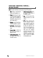
XA-3002 XA-6002 XA-6004 XA-5001 XA-8001 CONGRATULATIONS Congratulations for choosing an Xtreme Series power amplifier, by Directed Audio. This high performance product has been designed and engineered by Directed Electronics, the industry leader in high quality automotive security and audio equipment since 1990. With the Xtreme Series power amplifiers, Directed Audio continues to set new standards of performance, reliability, and affordability in the mobile electronics industry. Featuring high-efficiency MOSFET power supplies and flexible built-in crossovers housed in a rugged, extruded aluminum extrusion with carbon fiber style trim panels, Xtreme power amplifiers will excite and delight car audio enthusiasts with years of high performance audio reproduction. Xtreme Series amplifiers come with a two-year limited warranty if sold and installed by an authorized Directed dealer. If not installed by an authorized dealer, Xtreme Series amplifiers are covered by a one-year, parts-and-labor limited warranty. Be sure to retain your original purchase receipt, and refer to the warranty section of this guide for full details about your coverage. TABLE OF CONTENTS Congratulations . . . . . . . . . . . . . . . . . . . . . . . . . . . . . . . . . . . . . . . .2 Limited Two-Year Consumer Warranty . . . . . . . . . . . . . . . . . . . . . . . . .3 Features . . . . . . . . . . . . . . . . . . . . . . . . . . . . . . . . . . . . . . . . . . . .4 Warning . . . . . . . . . . . . . . . . . . . . . . . . . . . . . . . . . . . . . . . . . . . . .4 Installation Guidelines . . . . . . . . . . . . . . . . . . . . . . . . . . . . . . . . . . .4 Front Panel Connections/Controls . . . . . . . . . . . . . . . . . . . . . . . . . . .6 Input Wiring Diagrams . . . . . . . . . . . . . . . . . . . . . . . . . . . . . . . . . . .7 Crossover Settings and Gain Adjustment . . . . . . . . . . . . . . . . . . . . . . .9 Rear Panel Connections . . . . . . . . . . . . . . . . . . . . . . . . . . . . . . . . . .10 Speaker connections . . . . . . . . . . . . . . . . . . . . . . . . . . . . . . . . . . . .11 Bridge Mode . . . . . . . . . . . . . . . . . . . . . . . . . . . . . . . . . . . . . . . . . .13 CEA Specifications . . . . . . . . . . . . . . . . . . . . . . . . . . . . . . . . . . . . . .14 Specifications . . . . . . . . . . . . . . . . . . . . . . . . . . . . . . . . . . . . . . . . .15 2 © 2005 Directed Electronics—all rights reserved LIMITED TWO-YEAR CONSUMER WARRANTY Directed Electronics (Directed) promises to the original purchaser, to replace this product should it prove to be defective in workmanship or material under normal use, for a period of two years from the date of purchase by the dealer as indicated by the date code marking of the product PROVIDED the product was installed by an authorized Directed dealer. During this twoyear period, there will be no charge for this replacement PROVIDED the unit is returned to Directed, shipping pre-paid. If the unit is installed by anyone other than an authorized Directed dealer, the warranty period will be 1 year from the date of purchase by the dealer as indicated by the date code marking of the product. During this 1-year period there will be no charge for this replacement PROVIDED the unit is returned to Directed, shipping pre-paid. This warranty is non-transferable and does not apply to any unit that has been modified or used in a manner contrary to its intended purpose, and does not cover damage to the unit caused by installation or removal of the unit. This warranty is void if the product has been damaged by accident or unreasonable use, neglect, improper service or other causes not arising out of defects in materials or construction. ALL WARRANTIES INCLUDING BUT NOT LIMITED TO EXPRESS WARRANTY, IMPLIED WARRANTY, WARRANTY OF MERCHANTABILITY, FITNESS FOR PARTICULAR PURPOSE, AND © 2005 Directed Electronics—all rights reserved WARRANTY OF NON-INFRINGEMENT OF INTELLECTUAL PROPERTY ARE EXPRESSLY EXCLUDED TO THE MAXIMUM EXTENT ALLOWED BY LAW, AND DIRECTED NEITHER ASSUMES NOR AUTHORIZES ANY PERSON TO ASSUME FOR IT ANY LIABILITY IN CONNECTION WITH THE SALE OF THE PRODUCT. DIRECTED HAS ABSOLUTELY NO LIABILITY FOR ANY AND ALL ACTS OF THIRD PARTIES INCLUDING ITS AUTHORIZED DEALERS OR INSTALLERS. Unit must be returned to Directed, postage pre-paid, with: consumer’s name, telephone number, and address, authorized dealer’s name and address, and product description. IN ORDER FOR THIS WARRANTY TO BE VALID, YOUR UNIT MUST BE SHIPPED WITH PROOF OF INSTALLATION BY AN AUTHORIZED DIRECTED DEALER. ALL UNITS RECEIVED BY DIRECTED FOR WARRANTY REPAIR WITHOUT PROOF OF DIRECTED DEALER INSTALLATION WILL BE COVERED BY THE LIMITED 1-YEAR PARTS AND LABOR WARRANTY. Note: This warranty does not cover labor costs for the removal and reinstallation of the unit. BY PURCHASING THIS PRODUCT, THE CONSUMER AGREES AND CONSENTS THAT ALL DISPUTES BETWEEN THE CONSUMER AND Directed SHALL BE RESOLVED IN ACCORDANCE WITH CALIFORNIA LAWS IN SAN DIEGO COUNTY, CALIFORNIA. 3 FEATURES High-speed MOSFET power supplies Built-in 2-way variable crossovers Complimentary bipolar transistor outputs +6 or +12 dB switchable bass boost (+8dB on XA-6004) Either mono only (XA-8001, XA5001) or stereo/mono (XA6002). The XA-6004 can have rear bridged and front stereo or variations thereof. Adjustable input gain Power/status LEDs Thermal, short-circuit, over-current, and reverse polarity protection Chrome-plated RCA inputs Heavy duty screw terminals 2 ohm stereo stable/4 ohm mono stable WARNING High-powered car audio systems may produce sound pressure levels that exceed the threshold at which hearing loss may result. They may also impair a driver’s ability to hear traffic sounds or emergency vehicles. Use common sense and practice safe listening habits when listening to or adjusting your audio system. INSTALLATION GUIDELINES 1. Please read this owner’s manual carefully before installing this amplifier. 2. Disconnect the battery ground terminal prior to making any electrical connections. 3. Check for any hazards or obstructions such as gas tanks, fuel or brake lines, and wiring harnesses before mounting the amplifier. 4 4. Pick a mounting location that will provide adequate access and ventilation and protect the amplifier from heat, moisture, and dirt. 5. Avoid sharp metal areas when routing cables to the amplifier, and run RCA cables away from the power cables and other potentially noisy car harnesses. © 2005 Directed Electronics—all rights reserved 6. The amplifier should be grounded with a short, heavy gauge wire connected directly to the car at a bare metal surface, preferably scraped body sheet metal. Do not use factory ground locations, seat bolts, or brackets that are spotwelded. 7. Always fuse your power connection within 8 to 10 inches of the battery terminal. Use a fuse or circuit breaker rated slightly more than the on-board fuse(s) of the amplifier(s). The gauge of power wire used should take into account the total current draw of the system, and the length of wire used. IASCA and other auto sound competition organizations have charts available for this; you can also find a chart in the MECP study guide. Minimum wire gauge recommendations for the individual amplifiers are listed on the specification page. Always use the same gauge wire for the amplifier ground that you use for the power wire. Be sure to examine the battery ground cable of the vehicle, and if necessary, upgrade it by adding an additional ground wire that is the same gauge as the amplifier power wire. Remember, the amplifier can only deliver its rated output when it is © 2005 Directed Electronics—all rights reserved not current limited by the power and ground supply wires. 8. This amplifier is designed to drive a speaker load that measures from 2 to 4 ohms. Keep in mind that heat is the long-term enemy of automotive electronics and the lower your speaker load, the more heat is generated. For low impedance speaker applications or restricted ventilation installations, an external cooling fan may be advisable. 9. Battery and ground connections to the vehicle should be made with crimped ring terminals of the appropriate size (surface area is what counts); soldering the terminals after crimping is also recommended. 10. Due to the high-frequency MOSFET switching power supply, filtering the power cable is not generally required (remember that the amp can’t deliver full output if the power supply is restricted). Proper grounding of the signal source is mandatory for the amplifier to reach its performance peak. If the RCA inputs are not grounded adequately via the signal source, electrical noise from the vehicle may be picked up in the system. 5 FRONT PANEL CONNECTIONS/CONTROLS— XA-3002/XA-6002 NOTE: The numbers listed below are referenced on the Input Wiring Diagram. 1. PWR (LED blue) - when illuminated indicates that the amplifier is on. 2. HI Input (high level input) - Accepts 1v to 10v input from the headunit’s speaker output. The amplifier will automatically wake-up when the input is greater than 1V. 3. RCA Inputs - accepts RCA input from a source unit, preamplifier, or equalizer. 4. Level Control - continuously adjusts from 150mV to 5V for full power output. 5. Crossover Switch - activates low pass crossover, full (all pass), or high pass crossover. 6. Low-Pass Frequency Control - adjusts the frequency (50Hz–500Hz) of the lowpass crossover. 6 7. High-Pass Frequency Control - adjusts the frequency (50Hz–500Hz) of the highpass crossover. 8. Bass - sets the bass boost of the high-pass crossover to 0, 5 or 12dB of boost. 9. PRT (LED red) - illuminates when the PRT (Protection) function is active. Activates to protect the amplifier when the temperature is too high, the output has a DC offset, a short was detected on the output, or the amplifier power cables have been improperly connected (reverse power). If the temperature, DC offset, or short condition has cleared after approximately 10-seconds the amplifier will automatically recover. © 2005 Directed Electronics—all rights reserved INPUT WIRING DIAGRAM—XA-3002/XA-6002 2-CHANNEL XA-3002/XA-6002 1 2 3 4 INPUT PWR HI-INPUT 5 6 LEVEL X-OVER LOW PASS HI PASS 1.5 L 7 3 5V 90 8 9 BASS PRT 90 0.8 0.15V LPF HPF FULL 12dB 0dB 50Hz 500Hz 50Hz 500Hz 6dB R FRONT PANEL CONNECTIONS/CONTROLS—XA-6004 NOTE: The numbers listed below are referenced on the Input Wiring Diagram. 1. PWR (LED blue) - when illuminated indicates that the amplifier is on. 2. RCA Inputs (front) - accepts RCA input from a source unit, preamplifier, or equalizer. 3. Level Control (front) - continuously adjusts from 250mV to 5V for full power output. Low-Pass Frequency Control (front) adjusts the frequency (50Hz–500Hz) of the low-pass crossover. © 2005 Directed Electronics—all rights reserved High-Pass Frequency Control (front) adjusts the frequency (50Hz–500Hz) of the high-pass crossover. 4. HI Input (high level input) - Accepts 1v to 10v input from the headunit’s speaker output. The amplifier will automatically wake-up when the input is greater than 1V. 5. Level Control (rear) - continuously adjusts from 250mV to 5V for full power output. 7 Low-Pass Frequency Control (rear) adjusts the frequency (50Hz–500Hz) of the low-pass crossover. High-Pass Frequency Control (rear) adjusts the frequency (50Hz–500Hz) of the high-pass crossover. 6. RCA Inputs (rear) - accepts RCA input from a source unit, preamplifier, or equalizer. 7. PRT (LED red) - illuminates when the PRT (Protection) function is active. Activates to protect the amplifier when the temperature is too high, the output has a DC offset, a short was detected on the output, or the amplifier power 8 cables have been improperly connected (reverse power). If the temperature, DC offset, or short condition has cleared after approximately 10-seconds the amplifier will automatically recover. 8. Crossover Switch (front) - activates low pass crossover, full (all pass), or high pass crossover. 9. Bass (front) - sets the bass boost of the high-pass crossover to 0, or 8dB of boost. 10. Bass (rear) - sets the bass boost of the high-pass crossover to 0, or 8dB of boost. 11. Crossover Switch (rear) - activates low pass crossover, full (all pass), or high pass crossover. © 2005 Directed Electronics—all rights reserved INPUT WIRING DIAGRAM—XA-6004 4-CHANNEL XA-6004 FRONT REAR 1 2 PWR 3 INPUT LF 4 5 HI-INPUT FRONT REAR LEVEL LOW PASS HI PASS HI PASS LOW PASS LEVEL 90 90 1.4 6 90 90 5V 0.25V 50Hz 500Hz 50Hz FULL LPF HPF RF 500Hz 50Hz 8dB 0dB 8dB 0dB X-OVER BASS BASS 8 9 10 500Hz 50Hz INPUT LR PRT 1.4 4 0.5 4 7 500Hz 5V 0.5 0.25V FULL LPF HPF X-OVER RR 11 FRONT PANEL CONNECTIONS/CONTROLS— XA-5001/XA-8001 NOTE: The numbers listed below are referenced on the Input Wiring Diagram. 1. PWR (LED blue) - when illuminated indicates that the amplifier is on. 4. RCA Inputs - accepts RCA input from a source unit, preamplifier, or equalizer. 2. HI Input (high level input) - Accepts 1v to 10v input from the headunit’s speaker output. The amplifier will automatically wake-up when the input is greater than 1V. 5. Level Control - continuously adjusts from 150mV to 5V for full power output. 3. RCA Output - RCA output to another amplifier. 7. Low-Pass Frequency Control - adjusts the frequency (30Hz–250Hz) of the lowpass crossover © 2005 Directed Electronics—all rights reserved 6. Crossover Switch - activates low pass crossover, or full (all pass). 9 8. Bass - sets the bass boost of the high-pass crossover to 0, 6 or 12dB of boost. offset, a short was detected on the output, or the amplifier power cables have been improperly connected (reverse power). If the temperature, DC offset, or short condition has cleared after approximately 10-seconds the amplifier will automatically recover. 9. PRT (LED red) - illuminates when the PRT (Protection) function is active. Activates to protect the amplifier when the temperature is too high, the output has a DC INPUT WIRING DIAGRAM—XA-5001/XA-8001 MONO CHANNEL XA-5001/XA-8001 1 2 PWR HI-INPUT 3 4 OUTPUT INPUT 5 6 LEVEL 7 X-OVER 1.5 L 3 LOW PASS 8 BASS 9 PRT 50 0.8 5V 0.15V LPF FULL 30Hz 250Hz 0dB 12dB 6dB R 10 © 2005 Directed Electronics—all rights reserved REAR PANEL CONNECTIONS—XA-3002/XA-6002 NOTE: The numbers listed below are referenced on the Speaker Wiring Diagram. 10. Speaker Connections - Note that the two speakers & four speakers have been connected to the four terminal following the (+) and (-) graphic. Your speaker terminal may be marked (+) and (-) or there may be red dot by one terminal which means the same as (+). Connecting the speakers in this manner assures that the two speaker cones will move in and out together according to the original recording. If one of the two speakers is reversed, stereo imaging and bass response will be degraded. Refer to the specifications for the wire size to be used with your amplifier. 11. ATC Fuses - protects the amplifier from over current situations. See specification for fuse size for your amplifier. Note: The XA-3002 has only one fuse. 12. (+) 12 Volt Power - Connect this terminal through a FUSE or CIRCUIT BREAKER to the positive terminal of the vehicle battery or the positive terminal of an isolated audio © 2005 Directed Electronics—all rights reserved system battery. Refer to the specifications for the wire size to be used with your amplifier. WARNING: Always protect this power wire by installing a fuse or circuit breaker of the appropriate size within 12 inches of the battery terminal connection. Remote Turn On - This terminal turns on the amplifier when (+) 12 volt is applied to it. Connect it to the remote turn on lead of the head unit or signal source. If a (+) 12 volt remote turn lead is not available, a Remote Power Adapter (P/N #55000) can be used to supply a remote turn on signal. DO NOT connect this terminal to constant (+) 12 volt. Ground - Connect this terminal directly to the sheet metal chassis of the vehicle using the shortest wire necessary to make this connection. Always use wire of the same gauge or larger than the (+) 12 volt power wire. The chassis connection point should be scraped free of paint and dirt. Use only quality crimped and/or soldered connectors at both ends of this wire. DO NOT connect this terminal directly to the vehicle battery ground terminal or any other factory ground points. 11 SPEAKER WIRING DIAGRAM—XA-3002/XA-6002 2-CHANNEL XA-3002/XA-6002 SPEAKER 4 Ohm SPEAKER 4 Ohm Note: Model XA-3002 has one fuse. BRIDGED (R-) (R+) (L-) (L+) 10 FUSE +12V FUSE 11 REM GND 12 For bridging into a single speaker load, the XA-3002/6002 have the ability to be bridged, as shown in the diagram below: 2-CHANNEL XA-3002/XA-6002 BRIDGED SPEAKER 4 Ohm BRIDGED (R-) 12 (R+) (L-) (L+) FUSE FUSE +12V REM GND © 2005 Directed Electronics—all rights reserved SPEAKER WIRING DIAGRAM—XA-6004 4-CHANNEL XA-6004 FRONT RIGHT SPEAKER 4 Ohm LEFT SPEAKER 4 Ohm BRIDGED (R-) (R+) (L-) (L+) FUSE FUSE +12V REM GND FRONT REAR (R-) (R+) (L-) 10 RIGHT SPEAKER 4 Ohm (L+) 11 12 LEFT SPEAKER 4 Ohm REAR For bridging front and rear into single speaker loads, the XA-6004 has the ability to be bridged as shown in the diagram below: © 2005 Directed Electronics—all rights reserved 13 4-CHANNEL XA-6004 BRIDGED FRONT SPEAKER 4 Ohm BRIDGED (R-) (R+) (L-) (L+) FUSE FUSE +12V REM GND FRONT REAR (R-) (R+) (L-) (L+) SPEAKER 4 Ohm REAR 14 © 2005 Directed Electronics—all rights reserved SPEAKER WIRING DIAGRAM—XA-5001/XA-8001 The XA-5001, and XA-8001 amplifiers offer two positive and two negative output terminals for ease of connecting the speakers to the amplifier. Since these are mono amplifiers, the speaker connectors are paralleled internally. Each amplifier is stable to 2 ohms. MONO XA-6004 SPEAKER 4 Ohm (-) (-) (+) (+) 10 FUSE FUSE 11 +12V REM GND 12 SPEAKER 4 Ohm NOTE! The XA-5001 and XA-8001 are not designed to work in a bridged or strapped configuration. Attempting to apply these configurations will damage the amplifier and will not be covered under warranty. © 2005 Directed Electronics—all rights reserved 15 CROSSOVER SETTINGS AND GAIN ADJUSTMENT Your Xtreme Series power amplifier by Directed Audio needs to be adjusted carefully to achieve maximum performance. These are some guidelines to follow when fine-tuning the amplifier. 16 For full-range and simultaneous stereo/mono bass applications, the crossover selection switch should be set to FLAT. If the amplifier is driving your subwoofers, set the switch to LPF, and for mid-bass/midrange output, set to HPF. The crossover frequency control needs to be adjusted to suit your particular system. For subwoofer applications, try to keep the setting low enough to prevent the image smearing (you should not be able to hear male voices from the subwoofer) but not so low as to create a gap between the subwoofer and the midbass/midrange speakers. For mid-bass/midrange settings, try to keep the setting low enough to keep your sound stage in front of you, without overdriving the speaker. It will be to your advantage to spend some extra time with this adjustment, listening to familiar music or system set-up discs to achieve the kind of musical reproduction that you prefer. The gain adjustment allows you to set proper signal match for clean, quiet amplifier operation. For full-range and simultaneous stereo/mono bass applications, start by playing some music you are familiar with. With the gain adjustment on the amplifier in the middle of its rotation, bring up the volume on your head unit to the 3/4 volume setting or until you start to hear distortion or clipping. If you hear distortion before you reach the 3/4 volume setting of your head unit, reduce the gain setting on the amplifier and start to raise the head unit volume again. When you can listen to the music at or slightly above 3/4 on your head unit without audible distortion, slowly raise the gain of the amplifier until distortion is heard, then back off the gain until the distortion is not audible. This setting will allow you to reach full output with all but the quietest of source material, while avoiding excessive noise in the system. The same procedure should be used for adjusting the amplifier when the on-board crossover is set to LPF or HPF, but you will also have to take into consideration the effect that gain adjustment has on system frequency response and imaging. Again, plan on spending some time with music that you know, getting the gain and crossover settings the way you like. Test discs and analyzers may help with this process, but in the end it's your ears that count - listen to the music! © 2005 Directed Electronics—all rights reserved CEA SPECIFICATIONS XA-3002 Power Output: 55 Watts RMS x 2 at 4 ohms and < 1% THD+N Signal to Noise Ratio: -70 dBA (reference 1 Watt into 4 ohms) Additional Power Output: 80 Watts RMS x 2 at 2 ohms and < 1% THD+N XA-6002 Power Output: 100 Watts RMS x 2 at 4 ohms and < 1% THD+N Signal to Noise Ratio: -70 dBA (reference 1 Watt into 4 ohms) Additional Power Output: 150 Watts RMS x 2 at 2 ohms and < 1% THD+N XA-6004 Power Output: 60 Watts RMS x 4 at 4 ohms and < 1% THD+N Signal to Noise Ratio: -75 dBA (reference 1 Watt into 4 ohms) Additional Power Output: 75 Watts RMS x 4 at 2 ohms and < 1% THD+N XA-5001 Power Output: 150 Watts RMS x 1 at 4 ohms and < 1% THD+N Signal to Noise Ratio: -75 dBA (reference 1 Watt into 4 ohms) Additional Power Output: 250 Watts RMS x 1 at 2 ohms and < 1% THD+N XA-8001 Power Output: 300 Watts RMS x 1 at 4 ohms and < 1% THD+N Signal to Noise Ratio: -75 dBA (reference 1 Watt into 4 ohms) Additional Power Output: 400 Watts RMS x 1 at 2 ohms and < 1% THD+N © 2005 Directed Electronics—all rights reserved 17 SPECIFICATIONS Xtreme models XA-3002 XA-6002 XA-6004 XA-5001 XA-8001 Type 2-channel 2-channel 4-channel Mono block Mono block Maximum Power 300 watts 600watts 600 watts 500 watts 800 watts Damping Factor >150 >150 >75 >50 >50 Frequency Response 20Hz-20kHz 20Hz-20kHz 20Hz-20kHz 20Hz-250Hz 20Hz-20kHz +0, -3dB +0,-3dB +0,-3dB +0,-3dB +/- 1dB Crossover (12dB Slope) LP 50-500Hz LP 50-500Hz LP 50-500Hz LP 30-250Hz LP 30-250Hz Bass Boost (@ 50Hz) Switch Switch Switch Switch Switch 0, +6, +12dB 0, +6, +12dB +0, +8dB 0, +6, +12dB 0, +6, +12dB Input Sensitivity 150mV-5V 150mV-5V 250mV-5V 150mV-5V 150mV-5V Protection Thermal, Overcurrent, Short Circuit, Reverse Polarity Fuse Size 25A x 1 25A x 2 25A x 2 15A x 2 30A x 2 Min. Speaker Wire Gauge 12 12 12 12 12 Min. Power Wire Gauge 8 8 8 8 4 18 © 2005 Directed Electronics—all rights reserved © 2005 Directed Electronics - All rights reserved - G43100/05/10/15/20 10-05