1
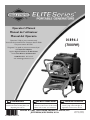
Operator’s Manual
Manuel de l'utilisateur
Manual del Operario
Questions? Help is just a moment away!
Vous avez des questions? Vous n'avez pas besoin d'aller
loin pour trouver de l'aide!
01894-1
(7000W)
Preguntas? La ayuda es justa un momento lejos!
Call: Generator Helpline
Appelez: Ligne d'assistance de Générateur
Llame: Línea Directa del Generador
1-800-743-4115 M-F 8-5 CT
web: www.briggsandstratton.com
WARNING
Before using this product, read this
manual and follow all Safety Rules and
Operating Instructions.
AVERTISSEMENT
ADVERTENCIA
Avant d’utiliser ce produit, veuillez lire
le manuel et suivre toutes les directives
relatives à la sécurité et à l’utilisation.
Antes de utilizar el producto, lea este
manual y siga todas las Reglas de
Seguridad e Instrucciones de Uso.
BRIGGS & STRATTON POWER PRODUCTS GROUP, LLC
JEFFERSON,WISCONSIN, U.S.A.
Manual No. 196746GS
Revision B (06/14/2006)
SAFETY RULES
SAVE THESE INSTRUCTIONS
TABLE OF CONTENTS
SAFETY RULES
Safety Rules. . . . . . . . . . . . . . . . . . . . . . . . . . . . . . . . . . . . 2-4
Know Your Generator . . . . . . . . . . . . . . . . . . . . . . . . . . . . . 5
Assembly. . . . . . . . . . . . . . . . . . . . . . . . . . . . . . . . . . . . . . 6-7
Operation . . . . . . . . . . . . . . . . . . . . . . . . . . . . . . . . . . . . 8-14
Maintenance . . . . . . . . . . . . . . . . . . . . . . . . . . . . . . . . . 15-16
Storage . . . . . . . . . . . . . . . . . . . . . . . . . . . . . . . . . . . . . . . . 16
Troubleshooting . . . . . . . . . . . . . . . . . . . . . . . . . . . . . . . . . 17
Notes . . . . . . . . . . . . . . . . . . . . . . . . . . . . . . . . . . . . . . . . . 18
Warranty . . . . . . . . . . . . . . . . . . . . . . . . . . . . . . . . . . . . . . 19
This is the safety alert symbol. It is used to
alert you to potential personal injury hazards.
Obey all safety messages that follow this
symbol to avoid possible injury or death.
The safety alert symbol ( ) is used with a signal word
(DANGER, CAUTION,WARNING), a pictorial and/or a
safety message to alert you to hazards. DANGER indicates
a hazard which, if not avoided, will result in death or
serious injury. WARNING indicates a hazard which, if not
avoided, could result in death or serious injury.
CAUTION indicates a hazard which, if not avoided, might
result in minor or moderate injury. CAUTION, when used
without the alert symbol, indicates a situation that could
result in equipment damage. Follow safety messages to
avoid or reduce the risk of injury or death.
EQUIPMENT
DESCRIPTION
Read this manual carefully and become familiar
with your generator. Know its applications, its
limitations and any hazards involved.
This generator is an engine–driven, revolving field,
alternating current (AC) generator. It was designed to
supply electrical power for operating compatible electrical
lighting, appliances, tools and motor loads.The generator’s
revolving field is driven at about 3,600 rpm by a singlecylinder engine.
WARNING
The engine exhaust from this product contains
chemicals known to the State of California to cause
cancer, birth defects, or other reproductive harm.
Hazard Symbols and Meanings
CAUTION! DO NOT exceed the generator’s
wattage/amperage capacity. See “Don’t Overload
Generator”.
Every effort has been made to ensure that information in
this manual is accurate and current. However, we reserve
the right to change, alter or otherwise improve the product
and this document at any time without prior notice.
Operator’s Manual
The Emission Control System for this generator is
warranted for standards set by the Environmental
Protection Agency and the California Air Resources Board.
For warranty information refer to the engine operator’s
manual.
Toxic Fumes
Explosive Pressure
Copyright © 2006 Briggs & Stratton Power Products
Group, LLC. All rights reserved. No part of this material
may be reproduced or transmitted in any form by any
means without the express written permission of Briggs &
Stratton Power Products Group, LLC.
2
Electrical Shock
Explosion
Chemical Burn
Fire
Hot Surface
SAFETY RULES
WARNING
DANGER
Storage batteries give off explosive hydrogen gas
during recharging.
Hydrogen gas stays near battery for a long time
after battery has been charged.
Slightest spark will ignite hydrogen and cause
explosion.
You can be blinded or severely injured.
Battery electrolyte fluid contains acid and is
extremely caustic.
Contact with battery fluid will cause severe
chemical burns.
Fuel and its vapors are extremely flammable and
explosive.
Fire or explosion can cause severe burns or
death.
WHEN ADDING OR DRAINING FUEL
• Turn generator OFF and let it cool at least 2 minutes before
removing fuel cap. Loosen cap slowly to relieve pressure in
tank.
• Fill or drain fuel tank outdoors.
• DO NOT overfill tank. Allow space for fuel expansion.
• If fuel spills, wait until it evaporates before starting engine.
• Keep fuel away from sparks, open flames, pilot lights, heat, and
other ignition sources.
• DO NOT light a cigarette or smoke.
WHEN STARTING EQUIPMENT
• Ensure spark plug, muffler, fuel cap and air cleaner are in place.
• DO NOT crank engine with spark plug removed.
WHEN OPERATING EQUIPMENT
• Do not tip engine or equipment at angle which causes fuel to
spill.
• This generator is not for use in mobile equipment or marine
applications.
WHEN TRANSPORTING OR REPAIRING
EQUIPMENT
• Transport/repair with fuel tank EMPTY or with fuel shutoff
valve OFF.
• Disconnect spark plug wire.
WHEN STORING FUEL OR EQUIPMENT WITH FUEL
IN TANK
• Store away from furnaces, stoves, water heaters, clothes
dryers or other appliances that have pilot light or other
ignition source because they can ignite fuel vapors.
• DO NOT allow any open flame, spark, heat, or lit cigarette
during and for several minutes after charging a battery.
• Wear protective goggles, rubber apron, and rubber gloves.
Using a generator indoors WILL KILL YOU
IN MINUTES.
Exhaust contains carbon monoxide, a
poison gas you cannot see or smell.
NEVER use in the home ONLY use outdoors and
or in partly enclosed
far from open windows,
areas such as garages. doors, and vents.
WARNING
WARNING
Running generator gives off carbon monoxide,
an odorless, colorless, poison gas.
Breathing carbon monoxide can cause nausea,
fainting or death.
• This generator does not meet U. S. Coast Guard Regulation
33CFR-183 and should not be used on marine applications.
• Failure to use the appropriate U. S. Coast Guard approved
generator could result in bodily injury and/or property
damage.
• Operate generator ONLY outdoors.
• Keep exhaust gas from entering a confined area through
windows, doors, ventilation intakes or other openings.
• DO NOT operate generator inside any building or enclosure
(even if doors or windows are open), including the generator
compartment of a recreational vehicle (RV).
3
SAFETY RULES
WARNING
WARNING
Generator produces powerful voltage.
Failure to isolate generator from power utility
can result in death or injury to electric utility
workers due to backfeed of electrical energy.
Unintentional sparking can result in fire or
electric shock.
• When using generator for backup power, notify utility
company. Use approved transfer equipment to isolate
generator from electric utility.
• Use a ground fault circuit interrupter (GFCI) in any damp or
highly conductive area, such as metal decking or steel work.
• DO NOT touch bare wires or receptacles.
• DO NOT use generator with electrical cords which are worn,
frayed, bare or otherwise damaged.
• DO NOT operate generator in the rain or wet weather.
• DO NOT handle generator or electrical cords while standing
in water, while barefoot, or while hands or feet are wet.
• DO NOT allow unqualified persons or children to operate or
service generator.
WHEN ADJUSTING OR MAKING REPAIRS TO YOUR
GENERATOR
• Disconnect the spark plug wire from the spark plug and place
the wire where it cannot contact spark plug.
WHEN TESTING FOR ENGINE SPARK
• Use approved spark plug tester.
• DO NOT check for spark with spark plug removed.
CAUTION
Exceeding generators wattage/amperage capacity can
damage generator and/or electrical devices connected
to it.
WARNING
• See “Don’t Overload Generator”.
• Start generator and let engine stabilize before connecting
electrical loads.
• Connect electrical loads in OFF position, then turn ON for
operation.
• Turn electrical loads OFF and disconnect from generator
before stopping generator.
Running engines produce heat.Temperature of
muffler and nearby areas can reach or exceed
150°F (65°C).
Severe burns can occur on contact.
Exhaust heat/gases can ignite combustibles,
structures or damage fuel tank causing a fire.
• DO NOT touch hot surfaces and avoid hot exhaust gases.
• Allow equipment to cool before touching.
• Keep at least 5 ft. (152 cm) clearance on all sides of generator
including overhead.
• Code of Federal Regulation (CFR) Title 36 Parks, Forests, and
Public Property require equipment powered by an internal
combustion engine to have a spark arrester, maintained in
effective working order, complying to USDA Forest service
standard 5100-1C or later revision. In the State of California a
spark arrester is required under section 4442 of the California
Public resources code. Other states may have similar laws.
CAUTION
Improper treatment of generator can damage it and
shorten its life.
• Use generator only for intended uses.
• If you have questions about intended use, ask dealer or call
1-800-743-4115.
• Operate generator only on level surfaces.
• DO NOT expose generator to excessive moisture, dust, dirt,
or corrosive vapors.
• DO NOT insert any objects through cooling slots.
• If connected devices overheat, turn them off and disconnect
them from generator.
• Shut off generator if:
-electrical output is lost;
-equipment sparks, smokes, or emits flames;
-unit vibrates excessively.
CAUTION
Excessively high operating speeds increase risk of injury
and damage to generator.
Excessively low speeds impose a heavy load.
• DO NOT tamper with governed speed. Generator supplies
correct rated frequency and voltage when running at governed
speed.
• DO NOT modify generator in any way.
4
KNOW YOUR GENERATOR
KNOW YOUR GENERATOR
Read this Operator’s Manual and safety rules before operating your generator.
Compare the illustrations with your generator, to familiarize yourself with the locations of various controls and
adjustments. Save this manual for future reference.
Oil Fill Cap
Fuel Tank
Air Cleaner
Rocker Switch Circuit
Breaker
Circuit Breakers (AC)
120 Volt AC, 20 Amp
Duplex Receptacles
Spark Arrester Muffler
120/240 Volt AC, 30 Amp
Locking Receptacle
Choke Lever
Data Tag
12 Volt DC
Receptacle
Grounding
Fastener
Battery
12 Volt DC Receptacle — Use this receptacle with
battery charge cables to charge a 12 Volt battery.
120 Volt AC, 20 Amp Duplex Receptacles — May be
used to supply electrical power for the operation of 120 Volt
AC, 20 Amp, single phase, 60 Hz electrical lighting, appliance,
tool and motor loads.
120/240 Volt AC, 30 Amp Locking Receptacle — May
be used to supply electrical power for the operation of
120 and/or 240 Volt AC, 30 Amp, single phase, 60 Hz
electrical lighting, appliance, tool and motor loads.
Air Cleaner — Protects engine by filtering dust and debris
Start Switch
Circuit Breakers (AC) — The 120 Volt AC, 20A duplex
receptacles are provided with "push to reset" circuit
breakers to protect the generator against electrical overload.
Data Tag – Provides model, revision and serial number of
generator. Please have these readily available if calling for
assistance.
Fuel Tank — Capacity of seven (7) U.S. gallons.
Start Switch — Turn to start the engine.
Grounding Fastener — If required, please consult a
qualified electrician, electrical inspector, or local agency
having jurisdiction.
Oil Fill Cap — Add oil to engine here.
Spark Arrester Muffler — Exhaust muffler lowers engine
noise and is equipped with a spark arrester screen.
Rocker Switch Circuit Breaker — The 120/240 Volt AC,
30A locking receptacle is provided with a rocker switch circuit
breaker to protect the generator against electrical overload.
This switch also controls all receptacles.
out of intake air.
Battery — Located behind plastic cover. 12 Volt DC sealed
battery provides power to start the engine.
Choke Lever — Used when starting a cold engine.
5
ASSEMBLY
ASSEMBLY
Attach Handle
You will need two 1/2” or 13mm wrenches to attach handle.
Your generator requires some assembly and is ready for
use after it has been properly serviced with the
recommended oil and fuel.
1.
If you have any problems with the assembly of your
generator, please call the generator helpline at
1-800-743-4115. If calling for assistance, please have the
model, revision, and serial number from the data tag available.
See “Know Your Generator” for data tag location.
Figure 1 — Attach Handle
Handle Pin
Lock Nut
Unpacking the Generator
1.
2.
3.
4.
Attach handle to right side of generator frame (viewing
unit from front), as shown in Figure 1, with a 60 mm
capscrew, flat washers, nylon washers, and lock nut.
Set the carton on a rigid flat surface.
Open carton completely by cutting each corner from
top to bottom.
Remove all packing material, carton fillers, etc.
Remove generator from shipping carton.
Ny
lon
Wa
she
rs
Flat Washers
60mm Capscrew
Nut
Washer
Handle Bracket
Nylon Washer
Nylon Washer
Handle Bracket
Washer
60mm Capscrew
Handle Pin
NOTE: DO NOT overtighten. Handle must be able to
move up and down freely.
2.
6
Raise handle and insert handle pin to move generator.
ASSEMBLY
BEFORE STARTING THE
ENGINE
Add Engine Oil
1.
Use clean, fresh, regular UNLEADED gasoline with a
minimum of 87 octane. DO NOT use fuel which
contains Methanol. DO NOT mix oil with fuel.
2.
Clean area around fuel fill cap, remove cap.
3.
Slowly add regular unleaded fuel to fuel tank. Be careful
not to overfill. Allow at least 2.25" of tank space for
fuel expansion (Figure 2).
• Place generator on a level surface.
CAUTION
Figure 2 - Fuel Expansion
2.25” Air Space
Any attempt to crank or start the engine before it has
been properly filled with the recommended oil will result
in equipment failure.
• Refer to engine operator’s manual for oil fill information.
• Damage to equipment resulting from failure to follow this
instruction will void warranty.
• Refer to engine operator’s manual and follow oil
recommendations and instructions.
Tank
Fuel
WARNING
NOTE: Check oil often during engine break–in. Refer to
engine operator’s manual for recommendations.
Fill tank to approximately 2.25” below top of
neck to allow for fuel expansion.
NOTE: The generator assembly rotates on a prelubricated
and sealed ball bearing that requires no additional
lubrication for the life of the bearing.
• Replace “1.5” with “2.25” fuel fill level given in engine manual.
• Failure to follow this instruction may cause fuel to overexpand
and spill from tank.
Add Fuel
4.
NOTE: This gasoline engine is certified to operate on
gasoline. Exhaust Emission Control System: EM (Engine
Modifications).
Remove Cover on Start Switch
Install fuel cap and let any spilled fuel evaporate before
starting engine.
A protective plastic cover is placed over the start switch to
prevent the generator from being started.
WARNING
Fuel and its vapors are extremely flammable and
explosive.
Fire or explosion can cause severe burns or
death.
• Open cap on battery float charger.
• Remove and discard plastic cover over the start switch
(Figure 3).
Figure 3 — Remove Cover on Start Switch
WHEN ADDING FUEL
• Turn generator OFF and let it cool at least 2 minutes before
removing fuel cap. Loosen cap slowly to relieve pressure in
tank.
• Fill fuel tank outdoors.
• DO NOT overfill tank. Allow space for fuel expansion.
• Wait for spilled fuel to evaporate before starting engine.
• Keep fuel away from sparks, open flames, pilot lights, heat, and
other ignition sources.
• DO NOT light a cigarette or smoke.
• Replace cap on battery float charger.
7
OPERATION
USING THE GENERATOR
Generator Location
Generator Clearance
System Ground
WARNING
The generator has a system ground that connects the
generator frame components to the ground terminals on
the AC output receptacles.The system ground is connected
to the AC neutral wire (the neutral is bonded to the
generator frame).
Exhaust heat/gases can ignite combustibles,
structures or damage fuel tank causing a fire.
• Keep at least 5 ft. (152 cm) clearance on all sides of generator
including overhead.
Place generator in a well ventilated area, which will allow
for removal of deadly exhaust gas. DO NOT place
generator where exhaust gas could accumulate and enter
inside or be drawn into a potentially occupied building.
Ensure exhaust gas is kept away from any windows, doors,
ventilation intakes or other openings that can allow exhaust
gas to collect in a confined area (Figure 4). Prevailing winds
and air currents should be taken into consideration when
positioning generator.
Special Requirements
There may be Federal or State Occupational Safety and
Health Administration (OSHA) regulations, local codes, or
ordinances that apply to the intended use of the generator.
Please consult a qualified electrician, electrical inspector, or
the local agency having jurisdiction.
• In some areas, generators are required to be registered
with local utility companies.
• If the generator is used at a construction site, there may
be additional regulations which must be observed.
Using a generator indoors WILL KILL YOU
IN MINUTES.
Connecting to a Building’s Electrical
System
Exhaust contains carbon monoxide, a
poison gas you cannot see or smell.
Connections for standby power to a building’s electrical
system must be made by a qualified electrician.The
connection must isolate the generator power from utility
power, and must comply with all applicable laws and
electrical codes.
WARNING
NEVER use in the home ONLY use outdoors and
or in partly enclosed
far from open windows,
areas such as garages. doors, and vents.
Generator produces powerful voltage.
Failure to isolate generator from power utility
can result in death or injury to electric utility
workers due to backfeed of electrical energy.
Figure 4 — Generator Clearance
• When using generator for backup power, notify utility
company. Use approved transfer equipment to isolate
generator from electric utility.
• Use a ground fault circuit interrupter (GFCI) in any damp or
highly conductive area, such as metal decking or steel work.
• DO NOT touch bare wires or receptacles.
• DO NOT use generator with electrical cords which are worn,
frayed, bare or otherwise damaged.
• DO NOT operate generator in the rain or wet weather.
• DO NOT handle generator or electrical cords while standing
in water, while barefoot, or while hands or feet are wet.
• DO NOT allow unqualified persons or children to operate or
service generator.
Exhaust Port
8
OPERATION
OPERATING THE
GENERATOR
WARNING
Running engines produce heat.Temperature of
muffler and nearby areas can reach or exceed
150°F (65°C).
Severe burns can occur on contact.
Exhaust heat/gases can ignite combustibles,
structures or damage fuel tank causing a fire.
Starting the Engine
IMPORTANT: Always unplug the battery float charger
before starting the generator.
• DO NOT touch hot surfaces and avoid hot exhaust gases.
• Allow equipment to cool before touching.
• Keep at least 5 ft. (152 cm) clearance on all sides of generator
including overhead.
• Code of Federal Regulation (CFR) Title 36 Parks, Forests, and
Public Property require equipment powered by an internal
combustion engine to have a spark arrester, maintained in
effective working order, complying to USDA Forest service
standard 5100-1C or later revision. In the State of California a
spark arrester is required under section 4442 of the California
Public resources code. Other states may have similar laws.
Disconnect all electrical loads from the generator. Follow
start instruction steps in numerical order:
1.
Make sure unit is on a level surface.
IMPORTANT: Failure to start and operate unit on a level
surface will cause the unit not to start or shut down during
operation.
2.
Follow start instructions given in engine operator’s
manual and turn start switch on generator to “Start”
position (Figure 5).
Jump Start Procedure
Figure 5 — Starter Switch
If the generator’s starting battery fails, use the following
instructions to jump start your generator.You can jump
start the generator using any 12 Volt automotive or utility
style storage battery.
1.
To prolong the life of starter components, DO NOT
hold starter switch in “Start” position for more than
15 seconds, and pause for 1 minute.
Unscrew the fuse holder and remove the generator’s
10 Amp in-line fuse (Figure 6).Verify the fuse is good
or replace with a known good fuse. Reinstall fuse in
the fuse holder.
Figure 6 — In-Line Fuse
NOTE: If engine starts but fails to run, or if unit shuts down
during operation, make sure unit is on a level surface and
check for proper oil level in crankcase.This unit may be
equipped with a low oil protection device. See engine
operator’s manual.
2.
9
Slide the red rubber boot off the generator’s battery
terminal and push it onto the red wire, thus
uncovering the POSITIVE battery terminal.
OPERATION
3.
Using standard automotive jumper cables, connect the
RED jumper cable clamp to the generator’s POSITIVE
battery terminal (Figure 7).
CAUTION
Exceeding generators wattage/amperage capacity can
damage generator and/or electrical devices connected
to it.
Figure 7 — Jumper Cable Connections
• See “Don’t Overload Generator”.
• Start generator and let engine stabilize before connecting
electrical loads.
• Connect electrical loads in OFF position, then turn ON for
operation.
• Turn electrical loads OFF and disconnect from generator
before stopping generator.
Grounding
Fastener
Stopping the Engine
1.
Unplug all electrical loads from generator panel
receptacles. NEVER start or stop engine with electrical
devices plugged in and turned on.
4.
Connect the other RED jumper cable clamp to the
starting battery’s POSITIVE battery terminal.
5.
Connect the BLACK jumper cable clamp to the
starting battery’s NEGATIVE battery terminal.
2.
Let engine run at no–load for 30 seconds to stabilize
the internal temperatures of engine and generator.
6.
Connect the other BLACK jumper cable clamp to the
GROUNDING FASTENER on the generator, as shown
in Figure 7.
3.
Turn start switch to “Stop” position.
7.
Start the generator as described in “Starting the
Engine” and remove jumper cables in reverse order of
connections.
Your generator has the capability of recharging a discharged
12 Volt automotive or utility style storage battery. DO
NOT use the unit to charge any 6 Volt batteries. DO NOT
use the unit to crank an engine having a discharged battery.
8.
Slide the red rubber boot back onto the generator’s
POSITIVE battery terminal.
Charging a Battery
DANGER
Storage batteries give off explosive hydrogen gas
during recharging.
Hydrogen gas stays near battery for a long time
after battery has been charged.
Slightest spark will ignite hydrogen and cause
explosion.
You can be blinded or severely injured.
Battery electrolyte fluid contains acid and is
extremely caustic.
Contact with battery fluid will cause severe
chemical burns.
If you have any questions, please call the Generator
Helpline at 1-800-743-4115, M-F 8-5 CT.
IMPORTANT: When jump starting, always wear proper eye
protection and never lean over battery. Inspect both
batteries before connecting booster cables. DO NOT jump
start a damaged battery. Be sure vent caps are tight and level.
Connecting Electrical Loads
• Let engine stabilize and warm up for a few minutes after
starting.
• Plug in and turn on the desired 120 and/or 240 Volt AC,
single phase, 60 Hz electrical loads.
• DO NOT connect 240 Volt loads to the 120 Volt
receptacles.
• DO NOT connect 3–phase loads to the generator.
• DO NOT connect 50 Hz loads to the generator.
• DO NOT OVERLOAD GENERATOR. See “Don’t
Overload Generator”.
• DO NOT allow any open flame, spark, heat, or lit cigarette
during and for several minutes after charging a battery.
• Wear protective goggles, rubber apron, and rubber gloves.
To recharge 12 Volt batteries, proceed as follows:
1.
10
Check fluid level in all battery cells. If necessary, add
ONLY distilled water to cover separators in battery
cells. DO NOT use tap water.
OPERATION
2.
If battery is equipped with vent caps, make sure they
are installed and are tight.
3.
If necessary, clean battery terminals.
4.
Connect battery charge cable connector plug to panel
receptacle identified by the words “12-VOLTS D.C.”
5.
Connect battery charge cable clamp with red handle
to positive (+) battery terminal (Figure 8).
How to Use the Battery Charger
Use battery float charger jack to keep the starting battery
charged and ready for use. Battery charging should be done
in a dry location, such as inside a garage.
1.
Figure 8 — Battery Connections
6.
Connect battery charge cable clamp with black handle
to negative (–) battery terminal (Figure 8).
7.
Start engine. Let engine run while battery recharges.
8.
When battery has charged, shut down engine
Plug charger into unit’s “Battery Float Charger” jack,
which is located on starter switch panel (Figure 9). Plug
battery charger into a 120 Volt AC wall receptacle.
Figure 9 — Battery Charger Jack
NOTE: Use an automotive hydrometer to test battery
state of charge and condition. Follow the hydrometer
manufacturer’s instructions carefully. Generally, a battery is
considered to be at 100% state of charge when specific
gravity of its fluid (as measured by hydrometer) is 1.260 or
higher.
2.
Unplug charger from unit and wall outlet when
generator is being started and while in operation.
3.
Keep charger plugged in when generator is not in use
to prolong battery life.The charger has a built in float
equalizer and will not overcharge battery, even when
plugged in for an extended period of time.
IMPORTANT: See “Battery Maintenance” on page 16 for
additional information.
COLD WEATHER
OPERATION
Under certain weather conditions (temperatures below
40°F [4°C] combined with high humidity), your generator
may experience icing of the carburetor and/or the
crankcase breather system.To reduce this problem, you
need to perform the following:
11
1.
Make sure generator has clean, fresh fuel.
2.
Open fuel valve (turn valve to open position).
3.
Use SAE 5W-30 oil (synthetic preferred, see engine
operator’s manual).
4.
Check oil level daily or after every eight (8) hours of
operation.
5.
Maintain generator following “Maintenance Schedule”
in engine operator’s manual.
6.
Shelter unit from elements.
OPERATION
Creating a Temporary Cold Weather
Shelter
1.
In an emergency, use the original shipping carton.
2.
Cut off top carton flaps and one long side of carton to
expose muffler side of unit. If required, tape up other
sides of carton to fit over generator as shown in
Figure 10.
6.
Start generator as described in the section “Starting
the Engine”, then place carton over generator. Keep at
least 5 ft. (152 cm) clearance on all sides of generator
including overhead with shelter in place.
WARNING
Running engines produce heat.Temperature of
muffler and nearby areas can reach or exceed
150°F (65°C).
Severe burns can occur on contact.
Exhaust heat/gases can ignite combustibles,
structures or damage fuel tank causing a fire.
Figure 10 — Permanent Cold Weather Shelter
Wind
• DO NOT touch hot surfaces and avoid hot exhaust gases.
• Allow equipment to cool before touching.
• Keep at least 5 ft. (152 cm) clearance on all sides of generator
including overhead.
• Remove shelter when temperatures are above 40°F [4°C].
3.
Cut appropriate slots to access receptacles of unit.
4.
Face exposed end away from wind and elements.
5.
Locate generator as described in the section
“Generator Location”. Keep exhaust gas from entering
a confined area through windows, doors, ventilation
intakes or other openings.
7.
Remove shelter when temperatures are above 40°F
[4°C].
8.
Turn engine OFF and let cool two (2) minutes before
refueling. Let any spilled fuel evaporate before starting
engine.
Creating a Permanent Cold Weather
Shelter
1.
Build a structure that will enclose three sides and the
top of the generator, making sure muffler side of
generator is exposed.
NOTE: Structure should hold enough heat created by the
generator to prevent icing problem.
2. DO NOT enclose generator any more than shown in
Figure 10.
WARNING
Running generator gives off carbon monoxide,
an odorless, colorless, poison gas.
Breathing carbon monoxide can cause nausea,
fainting or death.
3.
• Operate generator ONLY outdoors.
• Keep exhaust gas from entering a confined area through
windows, doors, ventilation intakes or other openings.
• DO NOT operate generator inside any building or enclosure
(even if doors or windows are open), including the generator
compartment of a recreational vehicle (RV).
12
Follow steps 3 through 8 as described previously in
“Creating a Temporary Cold Weather Shelter”.
OPERATION
RECEPTACLES
120 Volt AC, 20 Amp, Duplex
Receptacle
CAUTION
Each receptacle (Figure 12) is protected against overload by
a 20 Amp push–to–reset circuit breaker.
Receptacles may be marked with rating value greater
than generator output capacity.
Figure 12 — 120 Volt AC, 20 Amp, Duplex Receptacle
• NEVER attempt to power a device requiring more amperage
than generator or receptacle can supply.
• DO NOT overload the generator. See “Don’t Overload
Generator”.
120/240 Volt AC, 30 Amp, Locking
Receptacle
Use a NEMA L14–30 plug with this receptacle. Connect a
4–wire cord set rated for 250 Volt AC loads at 30 Amps (or
greater) (Figure 11).You can use the same 4–wire cord if
you plan to run a 120 Volt load.
Figure 11 — 120/240 Volt AC, 30 Amp Receptacle
4-Wire Cord Set
Use each receptacle to operate 120 Volt AC, single–phase,
60 Hz electrical loads requiring up to 2,400 watts (2.4 kW)
at 20 Amps of current. Use cord sets that are rated for
125 Volt AC loads at 20 Amps (or greater).
240V
120V
120V
W (Neutral)
12 Volt DC, 10 Amp Receptacle
This receptacle allows you to recharge a 12 Volt
automotive or utility style storage battery with the battery
charge cables provided (Figure 13).
Y (Hot)
NEMA L14-30
Figure 13 — 12 Volt DC, 10 Amp Receptacle
X (Hot)
Ground (Green)
This receptacle powers 120/240 Volt AC, 60 Hz, single
phase loads requiring up to 3,500 watts of power at
29.1 Amps for 120 Volts; 7,000 watts of power (7.0 kW) at
29.1 Amps for 240 Volts.The outlet is protected by a
30 Amp rocker switch circuit breaker.
This receptacle can not recharge 6 Volt batteries and can
not be used to crank an engine having a discharged battery.
See the section “Charging a Battery” (page 10) before
attempting to recharge a battery.
13
OPERATION
DON’T OVERLOAD
GENERATOR
4. Plug in and turn on the next load.
5. Again, permit the generator to stabilize.
6. Repeat steps 4 and 5 for each additional load.
NEVER add more loads than the generator capacity.Take
special care to consider surge loads in generator capacity,
as described above.
Capacity
You must make sure your generator can supply enough
rated (running) and surge (starting) watts for the items you
will power at the same time. Follow these simple steps:
1. Select the items you will power at the same time.
2. Total the rated (running) watts of these items.This is
the amount of power your generator must produce to
keep your items running. See Figure 14.
3. Estimate how many surge (starting) watts you will
need. Surge wattage is the short burst of power
needed to start electric motor-driven tools or
appliances such as a circular saw or refrigerator.
Because not all motors start at the same time, total
surge watts can be estimated by adding only the
item(s) with the highest additional surge watts to the
total rated watts from step 2.
Figure 14 - Wattage Reference Chart
Tool or Appliance
Essentials
Light Bulb - 75 watt
Deep Freezer
Sump Pump
Refrigerator/Freezer - 18 Cu. Ft.
Water Well Pump - 1/3 HP
Heating/Cooling
Window AC - 10,000 BTU
Window Fan
Furnace Fan Blower - 1/2 HP
Kitchen
Microwave Oven - 1000 Watt
Coffee Maker
Electric Stove - Single Element
Hot Plate
Family Room
DVD/CD Player
VCR
Stereo Receiver
Color Television - 27”
Personal Computer w/17” monitor
Other
Security System
AM/FM Clock Radio
Garage Door Opener - 1/2 HP
Electric Water Heater - 40 Gallon
DIY/Job Site
Quartz Halogen Work Light
Airless Sprayer - 1/3 HP
Reciprocating Saw
Electric Drill - 1/2 HP
Circular Saw - 7 1/4”
Miter Saw - 10”
Table Planer - 6”
Table Saw/Radial Arm Saw - 10”
Air Compressor - 1-1/2 HP
Example:
Tool or Appliance
Window Air
Conditioner
Refrigerator
Deep Freezer
Television
Light (75 Watts)
Rated (Running)
Watts
1200
Additional Surge
(Starting) Watts
1800
800
500
500
75
3075 Total
Running Watts
1600
500
1800 Highest
Surge Watts
Total Rated (Running) Watts
= 3075
Highest Additional Surge Watts
= 1800
Total Generator Output Required = 4875
Power Management
To prolong the life of your generator and attached devices,
it is important to take care when adding electrical loads to
your generator.There should be nothing connected to the
generator outlets before starting its engine.The correct
and safe way to manage generator power is to sequentially
add loads as follows:
1. With nothing connected to the generator, start the
engine as described in this manual.
2. Plug in and turn on the first load, preferably the largest
load you have.
3. Permit the generator output to stabilize (engine runs
smoothly and attached device operates properly.
Rated*
(Running)
Watts
Additional
Surge
(Starting)
Watts
75
500
800
800
1000
500
1200
1600
2000
1200
300
800
1800
600
1300
1000
1500
1500
2500
-
100
100
450
500
800
-
180
300
480
4000
520
-
1000
600
960
1000
1500
1800
1800
2000
2500
1200
960
1000
1500
1800
1800
2000
2500
*Wattages listed are approximate only. Check tool or
appliance for actual wattage.
14
SPECIFICATIONS & MAINTENANCE
SPECIFICATIONS
Starting Wattage . . . . . . . . . . . . . . . . . . . . 12,250 Watts
Wattage . . . . . . . . . . . . . . . . . . . . . . . . . . . . 7,000 Watts
AC Load Current
At 120 Volts . . . . . . . . . . . . . . . . . . . . . . . 58.3 Amps
At 240 Volts . . . . . . . . . . . . . . . . . . . . . . . 29.1 Amps
Phase . . . . . . . . . . . . . . . . . . . . . . . . . . . . . . . . . . 1-phase
Rated Frequency . . . . . . . . . . . . . . . . . . . . . . . 60 Hertz
Fuel Tank Capacity . . . . . . . . . . . . . . . . . . . 7 U.S. gallons
Shipping Weight . . . . . . . . . . . . . . . . . . . . . . . . . . 230 lbs.
2.
Place the oil drain tray foot tab in the slot on the base
of the generator, as shown.
3.
Follow the instructions given in the engine operator’s
manual for draining oil.
4.
After oil has drained, reinstall the oil drain plug.
5.
Remove the oil drain tray from under the oil drain plug
and clean up any spilled oil.
Changing Oil Filter
1. Place the half moon notch in the oil drain tray under
the oil filter (Figure 16).
GENERAL MAINTENANCE
RECOMMENDATIONS
Figure 16 — Changing Oil Filter With Oil Drain Tray
drain tray
notch
The Owner/Operator is responsible for making sure that
all periodic maintenance tasks are completed on a timely
basis; that all discrepancies are corrected; and that the unit
is kept clean and properly stored. NEVER operate a
damaged or defective generator.
NOTE: If equipped with inflatable tires, keep the air pressure
at the value marked on the tire or within 15 and 40 psi.
drain tray foot
NOTE: Should you have questions about replacing
components on your BSPP generator, please call
1-800-743-4115 for assistance.
Engine Maintenance
See engine operator’s manual for instructions.
An oil drain tray is provided for your convenience to
change the oil and oil filter. Store tray in a convenient
location for periodic maintenance.
2.
Place the oil drain tray foot tab in the slot on the base
of the generator, as shown.
3.
Follow the instructions given in the engine operator’s
manual for changing oil filter and adding oil.
4.
Remove the oil drain tray from under the oil filter and
clean up any spilled oil.
CAUTION
Avoid prolonged or repeated skin contact with used
motor oil.
Changing Oil
1. Place the half moon notch in the oil drain tray under
the oil drain plug (Figure 15).
• Used motor oil has been shown to cause skin cancer in
certain laboratory animals.
• Thoroughly wash exposed areas with soap and water.
Figure 15 — Changing Oil With Oil Drain Tray
KEEP OUT OF REACH OF CHILDREN. DON'T
POLLUTE. CONSERVE RESOURCES. RETURN
USED OIL TO COLLECTION CENTERS.
drain tray notch
drain tray foot
15
MAINTENANCE & STORAGE
Generator Maintenance
• Use a soft bristle brush to loosen caked on dirt or oil.
Generator maintenance consists of keeping the unit clean
and dry. Operate and store the unit in a clean dry
environment where it will not be exposed to excessive
dust, dirt, moisture or any corrosive vapors. Cooling air
slots in the generator must not become clogged with snow,
leaves or any other foreign material.
• Use a vacuum cleaner to pick up loose dirt and debris.
NOTE: DO NOT use a garden hose to clean generator.
Water can enter engine fuel system and cause problems. In
addition, if water enters generator through cooling air slots,
some of the water will be retained in voids and cracks of
the rotor and stator winding insulation.Water and dirt
buildup on the generator internal windings will eventually
decrease the insulation resistance of these windings.
The generator should be started at least once every seven
days and allowed to run at least 30 minutes. If this cannot
be done and you must store the unit for more than
30 days, use the following guidelines to prepare it for
storage.
WARNING
• Clean the generator as outlined in “Generator Cleaning”.
• Inspect cooling air slots and opening on generator.These
openings must be kept clean and unobstructed.
STORAGE
Generator Storage
• Check that cooling air slots and openings on generator
are open and unobstructed.
Unintentional sparking can result in fire or
electric shock.
WARNING
Storage covers can be flammable.
WHEN ADJUSTING OR MAKING REPAIRS TO YOUR
GENERATOR
• Disconnect the spark plug wire from the spark plug and place
the wire where it cannot contact spark plug.
WHEN TESTING FOR ENGINE SPARK
• Use approved spark plug tester.
• DO NOT check for spark with spark plug removed.
• DO NOT place a storage cover over a hot generator.
• Let equipment cool for a sufficient time before placing the
cover on the equipment.
Engine Storage
See engine operator’s manual for instructions.
Battery Maintenance
Other Storage Tips
Other than float charging, as described in “How to Use the
Battery Charger”, no maintenance is required for the
battery. Keep the battery and terminals clean and dry.
• To prevent gum from forming in fuel system or on
essential carburetor parts, add fuel stabilizer into fuel
tank and fill with fresh fuel. Run the unit for several
minutes to circulate the additive through the carburetor.
The unit and fuel can then be stored for up to
24 months. Fuel stabilizer can be purchased locally.
• DO NOT store fuel from one season to another unless
it has been treated as described above.
• Replace fuel container if it starts to rust. Rust and/or dirt
in fuel can cause problems if it's used with this unit.
• Store unit in a clean and dry area.
IMPORTANT: Battery charging should be performed in a
dry location, such as inside a garage.
Generator Cleaning
• Use a damp cloth to wipe exterior surfaces clean.
CAUTION
Improper treatment of generator can damage it and
shorten its life.
• DO NOT expose generator to excessive moisture, dust, dirt,
or corrosive vapors.
• DO NOT insert any objects through cooling slots.
16
TROUBLESHOOTING
TROUBLESHOOTING
Problem
No AC output is available, but
generator is running.
Generator runs good at no-load
but "bogs" down" when loads are
connected.
Generator will not start; or starts
and runs rough.
Cause
Correction
1.
One of the circuit breakers is
open.
1.
Reset circuit breaker.
2.
Fault in generator.
2.
Contact Authorized service facility.
3.
Poor connection or defective cord 3.
set.
Check and repair.
4.
Connected device is bad.
4.
Connect another device that is in
good condition.
1.
Short circuit in a connected load.
1.
Disconnect shorted electrical load.
2.
Generator is overloaded.
2.
See "Don't Overload Generator".
3.
Shorted generator circuit.
3.
Contact Authorized service facility.
1.
10 Amp in-line fuse is blown.
1.
Replace fuse.
2.
Discharged battery.
2.
Jump start generator and/or charge
battery.
3.
Failed battery.
3.
Replace battery.
4.
Low oil level.
4.
Fill crankcase to proper level or
place generator on level surface.
Generator shuts down during
operation.
Out of gasoline.
Fill fuel tank.
Generator lacks power.
Load is too high.
See "Don't Overload Generator".
17
NOTES
NOTES
18
BRIGGS & STRATTON POWER PRODUCTS GROUP, LLC PORTABLE GENERATOR OWNER WARRANTY POLICY
Effective February 1, 2006 replaces all undated Warranties and all Warranties dated before February 1, 2006
LIMITED WARRANTY
Briggs & Stratton Power Products Group, LLC will repair or replace, free of charge, any part(s) of the portable generator that is
defective in material or workmanship or both. Transportation charges on product submitted for repair or replacement under this
warranty must be borne by purchaser. This warranty is effective for the time periods and subject to the conditions stated below.
For warranty service, find the nearest Authorized Service Dealer in our dealer locator map at www.briggspowerproducts.com.
THERE IS NO OTHER EXPRESS WARRANTY. IMPLIED WARRANTIES, INCLUDING THOSE OF MERCHANTABILITY AND
FITNESS FOR A PARTICULAR PURPOSE, ARE LIMITED TO ONE YEAR FROM PURCHASE, OR TO THE EXTENT
PERMITTED BY LAW ANY AND ALL IMPLIED WARRANTIES ARE EXCLUDED. LIABILITY FOR INCIDENTAL OR
CONSEQUENTIAL DAMAGES ARE EXCLUDED TO THE EXTENT EXCLUSION IS PERMITTED BY LAW. Some states or
countries do not allow limitations on how long an implied warranty lasts, and some states or countries do not allow the
exclusion or limitation of incidental or consequential damages, so the above limitation and exclusion may not apply to you. This
warranty gives you specific legal rights and you may also have other rights which vary from state to state or country to country.
WARRANTY PERIOD
Consumer Use
Commercial Use
2 years*
1 year
*Second year parts only
The warranty period begins on the date of purchase by the first retail end user, and continues for the period of time stated above.
“Consumer Use" means personal residential household use by a retail consumer. “Commercial Use" means all other uses, including
use for commercial, income producing or rental purposes. Once equipment has experienced commercial use, it shall thereafter be
considered as commercial use for purposes of this warranty.
NO WARRANTY REGISTRATION IS NECESSARY TO OBTAIN WARRANTY ON BRIGGS & STRATTON PRODUCTS. SAVE
YOUR PROOF OF PURCHASE RECEIPT. IF YOU DO NOT PROVIDE PROOF OF THE INITIAL PURCHASE DATE AT THE TIME
WARRANTY SERVICE IS REQUESTED, THE MANUFACTURING DATE OF THE PRODUCT WILL BE USED TO DETERMINE
THE WARRANTY PERIOD.
ABOUT YOUR WARRANTY
We welcome warranty repair and apologize to you for being inconvenienced. Any Authorized Service Dealer may perform warranty
repairs. Most warranty repairs are handled routinely, but sometimes requests for warranty service may not be appropriate. For
example, warranty service would not apply if equipment damage occurred because of misuse, lack of routine maintenance,
shipping, handling, warehousing or improper installation. Similarly, the warranty is void if the manufacturing date or the serial number
on the portable generator has been removed or the equipment has been altered or modified. During the warranty period, the
Authorized Service Dealer, at its option, will repair or replace any part that, upon examination, is found to be defective under normal
use and service. This warranty will not cover the following repairs and equipment:
•
Normal Wear: Outdoor Power Equipment, like all mechanical devices, needs periodic parts and service to perform well. This
warranty does not cover repair when normal use has exhausted the life of a part or the equipment.
•
Installation and Maintenance: This warranty does not apply to equipment or parts that have been subjected to improper or
unauthorized installation or alteration and modification, misuse, negligence, accident, overloading, overspeeding, improper
maintenance, repair or storage so as, in our judgment, to adversely affect its performance and reliability. This warranty also does
not cover normal maintenance such as air filters, adjustments, fuel system cleaning and obstruction (due to chemical, dirt,
carbon, lime, and so forth).
•
Other Exclusions: This warranty excludes wear items such as o-rings, filters, etc., or malfunctions resulting from accidents,
abuse, modifications, alterations, or improper servicing or freezing or chemical deterioration. Accessory parts such as generator
adapter cord sets and storage covers are excluded from the product warranty. This warranty excludes used, reconditioned, and
demonstration equipment, equipment used for prime power in place of utility power, equipment used in life support applications,
and failures due to acts of God and other force majeure events beyond the manufacturers control.
BRIGGS & STRATTON POWER PRODUCTS GROUP, LLC
JEFFERSON, WI, USA
198189E, Rev 0. 02/01/2006