1
Dominion SX
User Guide
3.2.0
Copyright © 2010 Raritan, Inc.
DSX-v3.2-0T-E
December 2010
255-60-2000-00
This document contains proprietary information that is protected by copyright. All rights reserved. No
part of this document may be photocopied, reproduced, or translated into another language without
express prior written consent of Raritan, Inc.
© Copyright 2010 Raritan, Inc. All third-party software and hardware mentioned in this document are
registered trademarks or trademarks of and are the property of their respective holders.
FCC Information
This equipment has been tested and found to comply with the limits for a Class A digital device,
pursuant to Part 15 of the FCC Rules. These limits are designed to provide reasonable protection
against harmful interference in a commercial installation. This equipment generates, uses, and can
radiate radio frequency energy and if not installed and used in accordance with the instructions, may
cause harmful interference to radio communications. Operation of this equipment in a residential
environment may cause harmful interference.
VCCI Information (Japan)
Raritan is not responsible for damage to this product resulting from accident, disaster, misuse, abuse,
non-Raritan modification of the product, or other events outside of Raritan's reasonable control or not
arising under normal operating conditions.
To avoid potentially fatal shock hazard and possible damage to Raritan
equipment:
Do not use a 2-wire power cord in any product configuration.
Test AC outlets at your computer and monitor for proper polarity and
grounding.
Use only with grounded outlets at both the computer and monitor.
When using a backup UPS, power the computer, monitor and
appliance off the supply.
In Raritan products that require rack mounting, follow these precautions:
Operation temperature in a closed rack environment may be greater than
room temperature. Do not exceed the rated maximum ambient
temperature of the appliances (see Specifications (on page 227)).
Ensure sufficient airflow through the rack environment.
Mount equipment in the rack carefully to avoid uneven mechanical
loading.
Connect equipment to the supply circuit carefully to avoid
overloading circuits.
Ground all equipment properly, especially supply connections, such
as power strips (other than direct connections), to the branch circuit.
iii
Contents
How to - Dominion SX Essentials
xiv
Case 1. Upgrading SX Firmware via Web Browser.....................................................................xiv
Case 2. Configuring and Using Direct Port Access via SSH .......................................................xiv
Case 3. Using Exclusive Write Access via RSC .......................................................................... xv
Case 4. Configuring LDAP ........................................................................................................... xv
Case 5. Creating Power Association Group ................................................................................xvi
Case 6. Performing Factory Reset on SX .................................................................................. xvii
Case 7. Managing User Profiles on SX ...................................................................................... xvii
Case 8. Accessing Port Access on SX via RSC......................................................................... xvii
Case 9. Port Configuration ........................................................................................................ xviii
Case 10. CLI / SSH Connection to SX Port ............................................................................... xviii
Chapter 1 Preface
1
Audience ........................................................................................................................................ 1
Conventions ................................................................................................................................... 1
Acronyms ....................................................................................................................................... 1
Notices ........................................................................................................................................... 2
Chapter 2 Introduction
3
Dominion SX Overview .................................................................................................................. 3
Product Features ........................................................................................................................... 4
Comprehensive Console Management ............................................................................... 4
Strong Security and User-Authentication ............................................................................ 5
Reliable Connectivity ........................................................................................................... 5
Simplified User Experience ................................................................................................. 5
Package Contents.......................................................................................................................... 6
Chapter 3 Installation
7
Pre-Installation ............................................................................................................................... 8
Client Configuration ............................................................................................................. 8
Hardware Installation ..................................................................................................................... 8
Physical Installation of Dominion SX for Initial Configuration .............................................. 8
LED State ............................................................................................................................ 9
Initial Configuration Using the Graphical User Interface (GUI) ........................................... 9
Initial Configuration Using the Command Line Interface ................................................... 12
iv
Contents
Chapter 4 Initial Software Configuration
16
Dominion SX Initial Software Configuration ................................................................................. 16
Date / Time Configuration.................................................................................................. 18
Network Configuration ....................................................................................................... 19
Deployment .................................................................................................................................. 20
LAN Connection................................................................................................................. 20
Modem Connection (Optional)........................................................................................... 21
Chapter 5 Network Settings and Services
22
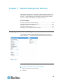
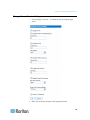
Configuring the Basic Network Settings ...................................................................................... 22
Give the Dominion SX a Name.......................................................................................... 22
Configure the Network Settings of Dominion SX............................................................... 23
Change the Discovery Ports .............................................................................................. 23
Configuring the Network Service Settings ................................................................................... 23
Change Network Service Settings ............................................................................................... 25
Configuring Modem Access ......................................................................................................... 26
Configuring IP Forwarding and Static Routes ............................................................................. 27
Enable IP Forwarding ........................................................................................................ 27
Add a New Static Route .................................................................................................... 28
Delete a Static Route ......................................................................................................... 29
Chapter 6 User Profiles and Groups
30
Managing User Profiles ............................................................................................................... 30
Display a List of User Profiles............................................................................................ 30
Create a User Profile ......................................................................................................... 31
Modify a User Profile ......................................................................................................... 32
Delete a User Profile ......................................................................................................... 33
Managing User Groups ................................................................................................................ 33
Display a List of User Groups ............................................................................................ 33
Create a User Group ......................................................................................................... 33
Modify a User Group ......................................................................................................... 37
Delete a User Group .......................................................................................................... 37
v
Contents
Chapter 7 Remote Authentication
38
Configuring RADIUS .................................................................................................................... 38
Configuring LDAP ........................................................................................................................ 39
Configuring TACACS+ ................................................................................................................. 41
Chapter 8 Port Configuration and Port Access Application
42
Port Keywords.............................................................................................................................. 43
Port Configuration ........................................................................................................................ 44
Direct Port Access ....................................................................................................................... 46
Direct Port Access via HTTP ....................................................................................................... 47
Anonymous Port Access .............................................................................................................. 47
Raritan Serial Console ................................................................................................................. 48
Raritan Serial Console Requirements for Java ........................................................................... 48
Java Runtime Environment (JRE) ..................................................................................... 49
Java Applets and Memory Considerations ........................................................................ 49
Raritan Serial Console Interface .................................................................................................. 51
Emulator ............................................................................................................................ 52
Edit ..................................................................................................................................... 59
Tools .................................................................................................................................. 60
Chat ................................................................................................................................... 64
Help ................................................................................................................................... 65
Standalone Raritan Serial Console Installation ................................................................. 65
Standalone Raritan Serial Client Requirements .......................................................................... 66
Setting Windows OS Variables.......................................................................................... 66
Setting Linux OS Variables................................................................................................ 70
Setting UNIX OS Variables................................................................................................ 70
Installing Standalone RSC for Windows ...................................................................................... 71
Launching RSC on Windows Systems ........................................................................................ 74
Installing RSC for Sun Solaris and Linux ..................................................................................... 75
Launching RSC on Sun Solaris ................................................................................................... 76
Chapter 9 Security
77
Security Settings .......................................................................................................................... 78
Login Settings .............................................................................................................................. 79
Local Authentication .......................................................................................................... 79
Login Handling ................................................................................................................... 80
Strong Password Settings ........................................................................................................... 80
Configure Kerberos ...................................................................................................................... 81
Certificates ................................................................................................................................... 81
Generate a Certificate Signing Request ............................................................................ 82
Install a User Key .............................................................................................................. 83
Install a User Certificate .................................................................................................... 84
SSL Client Certificate ................................................................................................................... 85
Enable Client Certificate Authentication ............................................................................ 86
Install a New Trusted Certificate Authority ........................................................................ 87
Remove a User-Added Certificate Authority ..................................................................... 87
vi
Contents
View a Certificate Authority ............................................................................................... 87
Manage the Client Certificate Revocation List (CRL) ........................................................ 87
Add a New Certificate Revocation List to the SX .............................................................. 87
Delete a Certificate Revocation List from the SX .............................................................. 88
View a Certificate Revocation List ..................................................................................... 88
Banner ......................................................................................................................................... 89
Security Profiles ........................................................................................................................... 90
About Security Profiles ...................................................................................................... 90
Select a Security Profile .................................................................................................... 90
Edit the Custom Profile ...................................................................................................... 91
Firewall ......................................................................................................................................... 91
Enable the Firewall ............................................................................................................ 92
Add an IPTables Rule ........................................................................................................ 92
Chapter 10 Logging
94
Configuring Local Event Logging ................................................................................................. 94
Enable the Event Log File ................................................................................................. 94
Enable System Logging..................................................................................................... 95
Enable Port Syslog ............................................................................................................ 95
Enable Port Logging .......................................................................................................... 96
Configure Input Port Logging............................................................................................. 97
Configure Encryption ......................................................................................................... 98
Block Port Access On Failure ............................................................................................ 98
Configuring SMTP Logging .......................................................................................................... 98
Enable SMTP Logging ....................................................................................................... 99
Select a New SMTP Event ................................................................................................ 99
Test SMTP Logging ......................................................................................................... 100
Configuring NFS Logging .......................................................................................................... 101
Configuring SNMP Logging ....................................................................................................... 102
Enable SNMP Logging .................................................................................................... 102
Create a New SNMP Destination .................................................................................... 103
Chapter 11 Maintenance
104
Managing the Local Event Log .................................................................................................. 104
Display the Local Event Log ............................................................................................ 105
Clear the Event Log ......................................................................................................... 106
Send the Event Log ......................................................................................................... 106
Displaying a Configuration Report ............................................................................................. 107
Backing Up and Restoring the SX ............................................................................................. 107
Back Up the SX ............................................................................................................... 107
Restore the SX ................................................................................................................ 108
Upgrading the SX Firmware ...................................................................................................... 109
Display the Current Firmware Version ............................................................................ 109
Upgrade the Firmware ..................................................................................................... 109
Display a Firmware Upgrade History ............................................................................... 111
vii
Contents
Performing a Factory Reset on the SX ...................................................................................... 111
Rebooting the SX ....................................................................................................................... 111
Chapter 12 Diagnostics
112
Network Infrastructure Tools ...................................................................................................... 112
Status of Active Network Interfaces ................................................................................ 112
Network Statistics ............................................................................................................ 113
Ping Host ......................................................................................................................... 114
Trace Route to Host ........................................................................................................ 114
Administrator Tools - Process Status ........................................................................................ 115
Chapter 13 Command Line Interface
116
Command Line Interface Overview ........................................................................................... 117
Accessing the Dominion SX Using CLI...................................................................................... 118
SSH Connection to the Dominion SX ........................................................................................ 118
SSH Access from a Windows PC .................................................................................... 118
SSH Access from a UNIX/Linux Workstation .................................................................. 119
Login ................................................................................................................................ 119
Telnet Connection to the Dominion SX...................................................................................... 120
Enabling Telnet ................................................................................................................ 120
Accessing Telnet from a Windows PC ............................................................................ 120
Local Port Connection to the Dominion SX ............................................................................... 121
Port Settings .................................................................................................................... 121
Connection....................................................................................................................... 121
To Change the Local Port Parameters: ........................................................................... 121
Navigation of the CLI ................................................................................................................. 122
Completion of Commands ............................................................................................... 122
CLI Syntax -Tips and Shortcuts ....................................................................................... 122
Common Commands for all Command Line Interface Levels ......................................... 122
Show Command .............................................................................................................. 124
Initial Configuration .................................................................................................................... 125
Setting Parameters .......................................................................................................... 125
Date and Time Configuration........................................................................................... 126
Setting Network Parameters............................................................................................ 126
CLI Prompts ............................................................................................................................... 127
CLI Commands .......................................................................................................................... 127
Security Issues ................................................................................................................ 129
Configuring Users and Groups ........................................................................................ 130
Command Language Interface Permissions ................................................................... 131
Target Connections and the CLI ................................................................................................ 131
Setting Emulation on a Target ......................................................................................... 131
Set Escape Sequence ..................................................................................................... 132
Port Sharing Using CLI .................................................................................................... 132
Configuring Authorization and Authentication (AA) Services .................................................... 132
Remote Services ............................................................................................................. 132
LDAP Configuration Menu ............................................................................................... 133
RADIUS Command ......................................................................................................... 135
TACACS+ Command ...................................................................................................... 136
viii
Contents
Administering the Dominion SX Console Server Configuration Commands ............................. 136
Configuring Events..................................................................................................................... 136
Configuring Log.......................................................................................................................... 137
Cleareventlog Command ................................................................................................. 137
Eventlogfile Command .................................................................................................... 137
eventsyslog Command .................................................................................................... 138
portsyslog Command ....................................................................................................... 138
nfsgetkey Command ........................................................................................................ 139
nfssetkey Command ........................................................................................................ 139
NFS Encryption Enable Command ................................................................................. 140
Portlog Command ............................................................................................................ 140
Decrypt Encrypted Log on Linux-based NFS Server ...................................................... 141
Sendeventlog Command ................................................................................................. 142
Vieweventlog Command.................................................................................................. 142
Configuring a Modem................................................................................................................. 143
Configuring Network .................................................................................................................. 146
Ethernetfailover Command .............................................................................................. 147
Interface Command ......................................................................................................... 147
IPForwarding Command.................................................................................................. 148
Name Command.............................................................................................................. 148
Ports Command ............................................................................................................ 149
Route Command ............................................................................................................. 149
Routeadd Command ....................................................................................................... 150
Routedelete Command.................................................................................................... 150
Getconfig Command ........................................................................................................ 151
Runconfig Command ....................................................................................................... 151
Configuring NFS ........................................................................................................................ 151
Configuring Ports ....................................................................................................................... 153
Ports Configuration Menu ................................................................................................ 153
Ports Config Command ................................................................................................... 153
Ports Keywordadd Command.......................................................................................... 157
Ports Keyworddelete Command ...................................................................................... 157
Configuring Services .................................................................................................................. 158
dpa Command ................................................................................................................. 159
Encryption Command ...................................................................................................... 162
HTTP Command .............................................................................................................. 162
HTTPS Command ........................................................................................................... 163
Logout Command ............................................................................................................ 163
LPA Command ................................................................................................................ 164
SSH Command ................................................................................................................ 164
Telnet Command ............................................................................................................. 165
fixedtcpwindow Command............................................................................................... 165
Configuring SNMP ..................................................................................................................... 165
SMNP Add Command ..................................................................................................... 166
SNMP Delete Command ................................................................................................. 166
SNMP Command ............................................................................................................. 166
Configuring Time........................................................................................................................ 167
Clock Command .............................................................................................................. 167
NTP Command ................................................................................................................ 167
Timezonelist Command ................................................................................................... 168
Configuring Users ...................................................................................................................... 168
Addgroup Command ....................................................................................................... 168
ix
Contents
Adduser Command .......................................................................................................... 169
Deletegroup Command ................................................................................................... 170
Deleteuser Command ...................................................................................................... 170
Editgroup Command ........................................................................................................ 170
Edituser Command .......................................................................................................... 171
Groups Command ........................................................................................................... 171
Users Command .............................................................................................................. 172
Connect Commands .................................................................................................................. 172
Configuring Power ..................................................................................................................... 172
Diagnostic Commands ............................................................................................................... 173
IPMI Commands ........................................................................................................................ 174
IPMIDISCOVER............................................................................................................... 174
IPMITOOL........................................................................................................................ 175
Listports Command ......................................................................................................... 177
Maintenance Commands ........................................................................................................... 179
Backup Command ........................................................................................................... 179
Cleareventlog Command ................................................................................................. 180
Factoryreset Command ................................................................................................... 180
Firmware Command ........................................................................................................ 181
Logoff Command ............................................................................................................. 181
Reboot Command ........................................................................................................... 182
Restore Command .......................................................................................................... 182
Sendeventlog Command ................................................................................................. 183
Upgrade Command ......................................................................................................... 183
Upgradehistory Command............................................................................................... 184
Userlist Command ........................................................................................................... 184
Vieweventlog Command.................................................................................................. 184
Security Commands................................................................................................................... 185
Banner Command ........................................................................................................... 185
Ftpgetbanner Command.................................................................................................. 185
Certificate Command Menu ............................................................................................. 186
Firewall Command ........................................................................................................... 188
IPtables Command .......................................................................................................... 189
Kerberos Command ........................................................................................................ 191
Loginsettings Commands ................................................................................................ 193
Idletimeout Command ..................................................................................................... 194
Inactiveloginexpiry Command ......................................................................................... 194
Invalidloginretries Command ........................................................................................... 195
Localauth Command ....................................................................................................... 195
Lockoutperiod Command ................................................................................................ 195
Singleloginperuser Command ......................................................................................... 196
Strongpassword Command ............................................................................................. 196
Unauthorizedportaccess Command ................................................................................ 197
Portaccess Command ..................................................................................................... 198
Securityprofiles Commands............................................................................................. 198
Profiledata Command ...................................................................................................... 198
x
Contents
Chapter 14 Intelligent Platform Management Interface
200
Discover IPMI Devices ............................................................................................................... 201
IPMI Configuration ..................................................................................................................... 202
Chapter 15 Power Control
205
Port Power Associations ............................................................................................................ 205
Create a Port Power Association..................................................................................... 205
Delete a Port Power Association ..................................................................................... 206
Power Strip Configuration .......................................................................................................... 207
Power Association Groups ........................................................................................................ 207
Power Control ............................................................................................................................ 208
Associations Power Control ....................................................................................................... 209
Power Strip Power Control ........................................................................................................ 210
Power Strip Status ..................................................................................................................... 211
CLI Command for Power Control............................................................................................... 211
CLI Port Power Association ............................................................................................. 211
CLI Power Strip Power Control........................................................................................ 217
CLI Association Power Control - Port Association .......................................................... 219
CLI Association Power Control - Group Association ....................................................... 221
CLI Power Strip Status .................................................................................................... 224
Appendix A Specifications
227
Dominion SX Models and Specifications ................................................................................... 227
Maximum Number of Connections for a Single User ................................................................ 230
Requirements............................................................................................................................. 231
Browser Requirements - Supported .......................................................................................... 231
Connectivity ............................................................................................................................... 232
Dominion SX Serial RJ-45 Pinouts ............................................................................................ 233
DB9F Nulling Serial Adapter Pinouts .............................................................................. 234
DB9M Nulling Serial Adapter Pinouts .............................................................................. 234
DB25F Nulling Serial Adapter Pinouts ............................................................................ 234
DB25M Nulling Serial Adapter Pinouts ............................................................................ 235
xi
Contents
Dominion SX Terminal Ports ..................................................................................................... 236
Dominion SX16 and SX32 Terminal Ports................................................................................. 237
Appendix B System Defaults
239
Initiate Port Access .................................................................................................................... 240
Supported Character Length of Various Field Types ................................................................ 241
Appendix C Certificates
243
Default SX Certificate Authority Settings ................................................................................... 244
Installing Dominion SX Server Certificate for Netscape Navigator ............................................ 244
Accept a Certificate (Session-Based) .............................................................................. 244
Install the Dominion SX Server Certificate in Netscape Navigator.................................. 244
Remove an Accepted Certificate ..................................................................................... 245
Installing a Third-Party Root Certificate ..................................................................................... 246
Install a Third-Party Root Certificate to Internet Explorer ................................................ 247
Install a Third-Party Root Certificate to Netscape Navigator ........................................... 247
Generate a CSR for a Third Party CA to Sign ................................................................. 248
Install Client Root Certificate into the DominionSX ......................................................... 250
Install Client Certificate into Internet Explorer ................................................................. 250
Importing Certificates for LDAP ................................................................................................. 250
Retrieve LDAP Certificate via Access from HTTP Interface ........................................... 250
Import Certificates from Windows XP .............................................................................. 251
Import Certificates from Dominion SX via CLI ................................................................. 252
Appendix D Server Configuration
254
Microsoft IAS RADIUS Server ................................................................................................... 254
Configure the Dominion SX to Use an IAS RADIUS Server ........................................... 254
Create an IAS Policy ....................................................................................................... 255
Cisco ACS RADIUS Server ....................................................................................................... 257
Configure the Dominion SX to use a Cisco ACS Server ................................................. 257
Configure the Cisco ACS Server ..................................................................................... 257
xii
Contents
TACACS+ Server Configuration ................................................................................................ 259
CiscoSecure ACS ...................................................................................................................... 260
Active Directory .......................................................................................................................... 263
Appendix E Modem Configuration
264
Client Dial-Up Networking Configuration ................................................................................... 264
Windows NT Dial-Up Networking Configuration ........................................................................ 264
Windows 2000 Dial-Up Networking Configuration ..................................................................... 267
Windows Vista Dial-Up Networking Configuration (Shared KSX II, SX) ................................... 271
Windows XP Dial-Up Networking Configuration ........................................................................ 272
Appendix F Troubleshooting
278
Page Access .............................................................................................................................. 278
Firewall ....................................................................................................................................... 279
Login .......................................................................................................................................... 280
Port Access ................................................................................................................................ 280
Upgrade ..................................................................................................................................... 281
Modem ....................................................................................................................................... 284
SSH Connection ........................................................................................................................ 284
iptables --list Hanging ................................................................................................................ 285
Display Issue with Japanese Characters when Using Teraterm ............................................... 285
Lines are Overwritten after Column 80 in Linux ........................................................................ 286
Index
287
xiii
How to - Dominion SX Essentials
This chapter includes 10 of the most common cases to help quickly
familiarize users with practical operation on Dominion SX units. Note that
data entered in the cases are created as examples, and could vary upon
different situations.
Case 1. Upgrading SX Firmware via Web Browser
To upgrade SX firmware version for enhanced features or
service patches:
1. Check Raritan support website for availability of latest firmware
version: (http://www.raritan.com/support/firmwareupgrades and look
for SX under Dominion Family)
2. Download the new SX firmware stored as UpgradePack from Raritan
support website to an FTP server (for example, a FileZilla server),
assuming that FTP server has an IP address of 192.168.51.204.
Extract the zip file to a folder under FTP root directory, for example:
\home\downloads\firmware\UpgradePack_2.5.6_3.1.0.5.2\Pack1of1.
Make sure the folder is accessible by an FTP user account that you
have.
3. Log in to the SX through a web browser. Choose Maintenance >
Firmware Upgrade. Enter FTP server IP address (for example,
192.168.51.204), FTP username and password, and the FTP folder
path where the extracted files are stored (in this example:
/UpgradePack_2.5.6_3.1.0.5.2\Pack1of1), and click Upgrade.
4. After firmware upgrade is completed, log in to SX and check the
firmware version again from: Maintenance > Firmware Version. You
can also check firmware upgrade history to make sure: Maintenance
> Firmware Upgrade History.
See Upgrade the Firmware (on page 109) for details.
Case 2. Configuring and Using Direct Port Access via SSH
To allow users to directly SSH into the serial target without
using SX GUI:
1. You may determine an IP address or TCP port on Dominion SX IP to
use for DPA or any port on Dominion SX. Since network the
administrator has no spare IP address, we will reuse the Dominion
SX IP address with different port.
2. Log back in to Dominion SX and select the port enabled for DPA in
Setup > Port Configuration.
xiv
How to - Dominion SX Essentials
3. Edit the DPA SSH TCP Port to which SSH client will connect, and
then click OK.
4. Log in to Dominion SX through a web browser. On the Setup >
Services page, select TCP port on Direct Port Access Mode, and
then click OK.
5. Launch the SSH client, such as Plink or PuTTY. Enter the IP address
and change the default TCP Port to connect to the port enabled (for
example, plink -ssh -P 2203 192.168.51.9).
See Direct Port Access (on page 46) for details.
Case 3. Using Exclusive Write Access via RSC
To ensure that you are the only user who has write access to a
serial target:
1. After logging in to SX via a web browser, "Port Access" tab is
selected by default.
2. Connect to a Port 4 by clicking on the hyperlink labeled "Port 4".
3. The Raritan Serial Console (RSC) application window launches with
Write Access enabled (icon indicated in green on status line at the
bottom of the window), unless the port has been occupied by another
user.
4. In the RSC window, choose Emulator > Get Write Lock (if some
other user has previously obtained Write Access, perform "Get Write
Access" first from the Emulator menu of RSC). The icon on the
status line will display Write Access (Lock) now, meaning now all
users can only view the port connection.
5. Log in to the device connected to the port and try interacting with the
device using the RSC panel. See Get Write Access for details.
6. To relinquish write lock in the RSC window, choose Emulator > Write
Unlock, and the icon on status line will display Write Access again,
meaning any other privileged users will re-gain Write Access now.
Case 4. Configuring LDAP
To configure SX to use LDAP/Active Directory® server for login
authentication:
1. After logging in to SX via a web browser, choose Setup > Remote
Authentication.
2. If the LDAP server has a backup server, enter the same parameters
(except the IP address) for the secondary LDAP server.
xv
Chapter 1: How to - Dominion SX Essentials
3. Click OK.
See Configuring LDAP (on page 39) for details.
Case 5. Creating Power Association Group
To associate the target server with more than one power outlets
physically connected to it:
1. After logging in to SX via a web browser, make sure a power strip
has been configured previously (To add a power strip: choose Setup
> Power Strip Configuration. See Power Strip Configuration (on
page 207) for details). Choose Setup > Port Power Association List
and click Add.
2. Select the SX port connected to the dual-powered server device with
which you want to associate outlets from the drop-down menu of
Port, and enter a description for it, such as "Internal Web Server
Pronto" (see Port Power Associations (on page 205) for details).
3. Select the Power Strip and outlet from the drop-down menu to match
how the device is connected to power. Click Add and the information
will appear in the text box as "[Power Strip Name] \ [outlet 1]". Select
the same power strip and another outlet, then click Add to add it.
Another line will display in the text box as "[Power Strip Name] \
[outlet 2]". Click OK to commit the changes.
4. Choose Setup > Power Association Group List and click Add (see
Power Association Groups (on page 207) for details).
5. Enter a group name and description, then the port ID from the
"Available" box (multiple selection is permitted), and click Add to add
to the "Selected" box.
6. Click OK to commit changes.
See Power Strip Configuration (on page 207) for details on how to add
power strips to SX management first. If this wasn't already done, see
Port Power Associations section to map power strip outlet to a target
server connected to an SX serial port, and then see Power Association
Groups (on page 207) for details on how to group multiple power outlets
physically connected to that same target server.
xvi
How to - Dominion SX Essentials
Case 6. Performing Factory Reset on SX
To set SX configuration back to factory defaults through the
GUI:
1. Log in to SX via a web browser with your login username and
password, such as (admin/raritan).
2. Choose Maintenance > Factory Reset. You will be prompted to
confirm your decision.
3. Do not power off SX unit as it reboots with default configuration.
4. You will be re-directed to the login page after the unit is rebooted. If
you try to log in for the first time after reset, you'll be advised that you
are now in the factory default mode, and promoted for changing
password after logging in with default username and password.
See Performing a Factory Reset on the SX (on page 111) for details.
Case 7. Managing User Profiles on SX
To create, update, or delete an SX user:
1. Log in to SX via a web browser with your login username and
password, such as (admin/raritan).
2. Choose User Management > User List and the page will display a list
of user profiles created.
3. To create a user profile, click Add New User.
4. To modify an existing user profile, see Modify a User Profile (on
page 32) for details.
5. To delete an existing user profile, see Delete a User Profile (on
page 33) for details.
See Create a User Profile (on page 31) for details.
Case 8. Accessing Port Access on SX via RSC
To access an SX serial target through Raritan Serial Client
(RSC):
1. Log in to SX via a web browser with your login username and
password, such as (admin/raritan).
xvii
Chapter 1: How to - Dominion SX Essentials
2. Choose the Port Access Tab, and click the port name you wish to
access, for example, Port 1.
3. Select YES to proceed through security warning(s).
4. The Raritan Serial Console (RSC) will be launched in a separate
window - press the Enter key to "wake up" session.
5. Type in target system's native commands in the RSC
window/console.
6. Choose Emulator > Exit. Click YES on the confirmation dialog to
exit and the RSC window will close.
See Raritan Serial Console (on page 48) for details.
Case 9. Port Configuration
These steps allow you to configure SX serial ports to set up correct serial
communications parameters (for example, baud rate, data bits, stop bit,
flow control) and terminal emulation mode to match the serial targets
connected to the ports, and name the ports to more easily identify the
targets.
To configure SX serial ports to set up correct serial
communications parameters:
1. Log in to SX via a web browser with your login username and
password, such as (admin/raritan).
2. Choose Setup > Port Configuration, check the box associated with
the port number you wish to configure, and click Edit.
See Port Configuration (on page 44) for details.
Case 10. CLI / SSH Connection to SX Port
To access the SX unit and SX ports using text-based command
lines:
1. SSH access from a Windows® PC:
a. Launch the SSH client software (such as Plink or PuTTY).
b. Enter IP address of SX server (for example, 192.168.0.192) and
the TCP port if applicable.
c.
Select SSH (using default configuration port 22), and click Open.
d. Enter username and password when prompted: login as:
admin password: raritan (default value)
xviii
How to - Dominion SX Essentials
e. The console will display all the ports on the SX unit with port
numbers.
f.
Enter a port number at the prompt, for example: admin> 1
g. To return to the SX console, enter the escape sequence
characters. For example, simultaneously press the control and
closed bracket key (]).
h. To exit the target serial console session, enter the letter "q" to
quit. You will be re-directed to the SX console, and the port serial
console session is now closed.
2. SSH access from a UNIX® Workstation
a. Enter the following command to log in: ssh -l admin
192.168.0.192
b. Enter the admin username and password: login as: admin
The password prompt appears. Enter the default password:
raritan
c.
The console will display all the ports on SX unit with port
numbers.
d. Enter a port number at the prompt, for example: admin> 1
e. To return to the SX console, enter the escape sequence
characters. For example, simultaneously press the control and
closed bracket key (]).
f.
To exit the target serial console session, enter the letter "q" to
quit. You will be re-directed to the SX console, and the port serial
console session is now closed.
See SSH Connection to the Dominion SX for details.
xix
Chapter 1
Preface
The Dominion SX User Guide provides the information needed to install,
set up and configure, access devices such as routers, servers, switches,
VPNs, and power strips, manage users and security, and maintain and
diagnose the Dominion SX secure console server.
In This Chapter
Audience ....................................................................................................1
Conventions ...............................................................................................1
Acronyms ...................................................................................................1
Notices .......................................................................................................2
Audience
The primary audiences for this guide are infrastructure administrators
and installers who are responsible for installing and setting up devices
such as secure console servers. Other interested audiences are
operators and observers who use the Dominion SX to reach other
devices.
Conventions
This guide uses the following conventions:
Example
/usr/local/java
Description
Monospaced text indicates file names, paths,
directories, or screen text.
Enter
Menu items, Key words and Keyboard keys are bold.
<ip address>
Monospaced, italicized text indicate where the user
would substitute a value in a command.
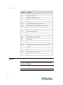
Acronyms
This guide uses the following acronyms:
Acronym
AD
Meaning
Active Directory®
CC
Command Center
CLI
Command Line Interface
1
Chapter 1: Preface
Acronym
CSC
Meaning
Common Socket Connection
DPA
Direct Port Access
HTTP
Hypertext Transfer Protocol
HTTPS
HTTP Secure (over SSL)
LAN
Local Area Network
LDAP
Lightweight Directory Access Protocol
LDAP/S
Lightweight Directory Access Protocol/Secure
NFS
Network File System
NTP
Network Time Protocol
PPP
Point to Point Protocol
RADIUS
Remote Authentication Dial In User Service
RSC
Raritan Serial Console
SMTP
Simple Mail Transfer Protocol
SSH
Secure Shell
SSL
Secure Sockets Layer
SNMP
Simple Network Management Protocol
TACACS+
Terminal Access Controller Access Control System
(PLUS)
TLS
Transport Layer Security
UTC
Universal Time Coordinated
VLAN
Virtual Local Area Network
VPN
Virtual Private Network
Notices
Important: Cautionary information that warns of possible affects on
the users, corruption risks, and actions that may affect warranty
and service coverage.
Note: General information that is supplemental to the text.
2
Chapter 2
Introduction
In This Chapter
Dominion SX Overview..............................................................................3
Product Features .......................................................................................4
Package Contents .....................................................................................6
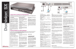
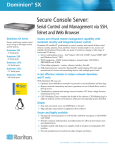
Dominion SX Overview
The Dominion SX Series of Serial over IP Console Servers offers
convenient and secure remote access and control through LAN/WAN,
Internet, or Dial-up modem to all networking devices.
The Dominion SX:
Provides a non-intrusive solution for managing network elements
and does not require any installation of software agents on the target
device
Connects to any networking device (server, firewall, load balancer,
and so forth) through the serial port and provides the ability to
remotely and securely manage the device using a Web browser
Dominion SX is a fully configured stand-alone product in a standard 1U
high 19" rack mount chassis.
3
Chapter 2: Introduction
Product Features
Comprehensive Console Management
4
Remote Management: Access, monitor, administer, and troubleshoot
up to 48 target devices (depending on the model) via Secure Socket
Shell (SSH), Telnet, Local Port, or Web browser with only one IP
address.
Direct Port Access via TCP/IP address per port; or one IP address
and TCP Port numbers.
Notification: Create notification messages by email alerts.
Collaborative Management and Training: Access ports
simultaneously; up to 10 users per port at any time.
SecureChat™: “Instant message” and other Secure Sockets Layer
(SSL) users can securely collaborate on device management,
troubleshooting, and training activities.
Get History: Get up to 256 KB (64KB on units with 64MB SDRAM;
256KB on units with 128MB SDRAM) of recent console history to
assist with debugging.
Supports VT100, VT220, VT 320, and ANSI terminal emulation.
Up to a 5,000 line copy-paste buffer.
Local port access.
SNMP traps.
SYSLOG.
Logging to Network File System (NFS) Server.
Comprehensive SNMP traps.
Port alerts with keyword triggers.
Three Levels of User Access:
Administrator: Has read and write access to the console window;
can modify the configuration of unit.
Operator: Has read and write access to the console window;
cannot modify the configuration of unit (except own password).
Observer: Has read-only access to the console window; cannot
modify the configuration of unit (except own password).
Chapter 2: Introduction
Strong Security and User-Authentication
SSHv2 Support
Encryption Security: 128-bit SSL handshake protocol and RC4
encryption.
User Authentication Security: local database, remote authentication
Supports RADIUS, TACACS+, LDAP, LDAP(S), Microsoft Active
Directory®, and NTP.
Supports user-defined and installable security Certificates.
Reliable Connectivity
Optional Modem Connectivity: For emergency remote access if the
network has failed.
Target Device Connectivity: Simplified RJ45-based CAT 5 cable
scheme; serial port adapters are available from Raritan.
Local Access for "crash-cart" applications.
See Connectivity (on page 232) for a list of necessary Dominion SX
hardware (adapters and/or cables) for connecting the Dominion SX to
common Vendor/Model combinations.
Simplified User Experience
Telnet
SSH
Browser-based Interface: The new GUI provides intuitive access to
target devices (click the appropriate button to select the desired
target device).
Upgrades: Built-in firmware upgrade capability through FTP or LPA
and integrated with Command Center (CC) and SSH.
5
Chapter 2: Introduction
Package Contents
Each Dominion SX ships with the following:
6
(1) Dominion SX unit with mounting kit (rack-mount kit is optional on
some units)
(1) Raritan Dominion SX User Guide CD-ROM, which contains the
installation and operations information for the Dominion SX
(1) Printed Dominion SX Quick Setup Guide
(1) Power cord
(1) Release Notes
(1) Packing List page
(1) RJ45 serial loop-back plug
(1) DB9 Factory Reset Adapter for some units (Other units have a
reset switch and do not require an adapter.)
Chapter 3
Installation
There are two ways of completing the initial network installation of the
Dominion SX:
Using a serial cable with a VT100/equivalent, such as a PC with
HyperTerminal
Using Ethernet (with an installation computer)
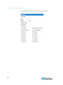
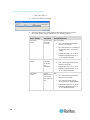
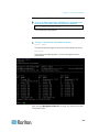
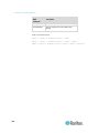
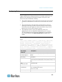
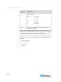
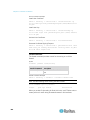
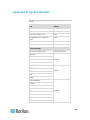
This section describes the steps necessary to configure Dominion SX for
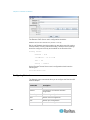
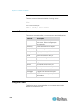
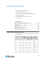
use on a local area network (LAN). The following table describes the
factory default network settings that come with the Dominion SX. After
units are connected to the network, these factory default settings allow
you to configure the Dominion SX for normal use.
Default Network Settings
Internet Address (IP)
192.168.0.192
Gateway Address
192.168.0.192
Subnet Mask
255.255.255.0
CSC Port Address
5000
Port Address for CC
Discovery
5000
Username
admin (all
lowercase)
Password
raritan (all
lowercase)
Note: The settings listed in the table above are applicable only if no
DHCP server is running on the network. If a DHCP server is running on a
local network, the Dominion SX unit is assigned a different IP address
than the default by the DHCP server.
In This Chapter
Pre-Installation ...........................................................................................8
Hardware Installation .................................................................................8
7
Chapter 3: Installation
Pre-Installation
Ensure that you have the correct cabling ready to connect to the serial
consoles of the target server(s) or other serially managed devices that
provide a console port.
The following sections describe information that you must supply to
complete the configuration of the Dominion SX. Obtain all required
configuration information prior to performing the configuration steps. If
you are uncertain of any information, contact your system administrator
for assistance.
Client Configuration
1. Disable Proxies in the installation computer web browser.
Use "no Proxies" or temporarily add 192.168.0.192 to the list of
URLs for which no proxy is configured.
2. Enable Java Applet Execution in the installation computer web
browser for the console client application (RSC).
3. Access the unit through your installation computer Web browser on
the same subnet by typing the URL https://192.168.0.192 in the
address bar.
Hardware Installation
Physical Installation of Dominion SX for Initial Configuration
1. Use a computer with a network card and crossover network cable.
This computer will be referred to as the 'installation computer.'
2. Physically mount the unit in an ergonomically sound manner. The
unit is designed to be easily rack-mounted, and rack mounting is
recommended.
3. Connect the crossover network LAN cable to the primary LAN
connection (LAN 1 on models with two Ethernet interfaces) on the
back of the chassis.
4. Connect the other end of the network LAN cable to the network card
in the installation computer.
8
Chapter 3: Installation
5. Connect the female end of the external power cord to the back of the
chassis.
6. Connect the male end of the external power cord to the power supply
outlet.
7. Power ON the Dominion SX unit.
Note: The unit will perform a hardware and firmware self-test, then start
the software boot sequence, which takes a short time. It is complete
when the light turns on and remains on.
After completion of the hardware and firmware self-test and the software
boot sequence, perform the initial configuration tasks using the Graphical
User Interface (GUI) or the Command Line Interface (CLI) as described
in the following sections.
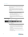
LED State
On the front panel of the Dominion SX unit, there are LED indicators on
each side of the device. The green LED will be lit at the same time the
blue LED is lit. The blue LED indicator will blink blue in the following
three cases:
1. Ethernet packets are received or transmitted.
2. Serial data are received or transmitted.
3. Watchdog timer is reset to 0. The LED blinks on a periodic basis as
the watchdog timer reaches a certain value, and then is reset to 0.
Initial Configuration Using the Graphical User Interface (GUI)
To initially configure the Dominion SX unit from the GUI , follow these
steps.
Network Access
1. Ensure that the installation computer has the route for 192.168.0.192
and that it can communicate with IP address 192.168.0.192.
2. To check the route table in Windows®, type the command route print
in a Command window on the installation computer. If 192.168.0.192
is on the gateway list, proceed to step 3. Otherwise, add
192.168.0.192 to the gateway list using the appropriate DOS or
UNIX® CLI command:
Windows 98/2000/NT system: route add 192.168.0.192
<INSTALLATION COMPUTER IP ADDRESS>.
[Example: route add 192.168.0.192 15.128.122.12
9
Chapter 3: Installation
UNIX (including Sun Solaris) system:
route add 192.168.0.192 <CLIENT_HOST IP ADDRESS>
-interface.
[Example: route add 192.168.0.192 15.128.122.12
-interface]
3. Type ping 192.168.0.192. Go to step 4 if you receive a
successful reply from the Dominion SX unit. If an error occurs, verify
that the default IP address is entered correctly and that a route to
that IP address exists.
4. Use the installation computer to connect to the unit by launching a
browser and typing the factory default IP address 192.168.0.192 in
the Web browser's address bar.
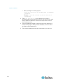
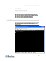
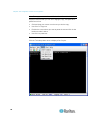
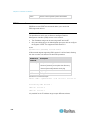
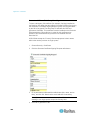
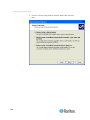
5. The computer displays the security screens before you can log in.
10
Chapter 3: Installation
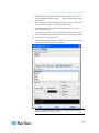
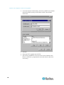
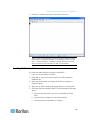
6. If you click View Certificate on the Security Alert-Certificate page, a
Certificate dialog appears.
See Security (on page 77) and Appendix C: Certificates (see
"Certificates" on page 243) for information about installing
certificates.
11
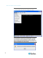
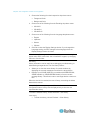
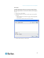
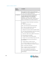
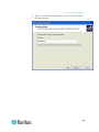
Chapter 3: Installation
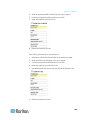
The login dialog appears after you finish viewing the security alerts
and the Certification Information screen.
Log in with the default username admin and password raritan. Use all
lowercase letters.
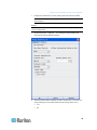
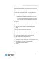
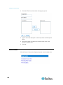
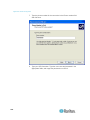
7. After login, the Dominion SX prompts you to change the default
password:
8. Type a new secure password then retype it (Remember the new
password for next login.)
9. Click OK. The Dominion SX Port Access page opens. (See Initial
Software Configuration (on page 16) for details.)
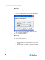
Initial Configuration Using the Command Line Interface
To initially configure the Dominion SX unit from the Command Line
Interface, follow the steps below.
1. Connect the serial port of your Installation Computer to the Terminal
serial port on your Dominion SX. This port is a DB9-Male port on
most models, except ALL dual-power dual-LAN models, including
DSXA-48, which have an RJ45 connector for a terminal port.
2. Open a terminal emulation program, such as HyperTerminal, to
connect to the Dominion SX unit. The serial communication
parameters are 9600 bps, No parity, 8 data bits, 1 stop bit and None
flow control.
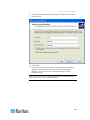
3. Power ON the Dominion SX.
4. Log in using the default username admin and the default password
raritan when prompted.
Once logged in, a prompt to change the password appears.
12
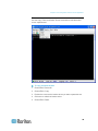
Chapter 3: Installation
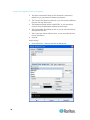
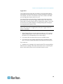
5. Type a new password, and then retype it (Remember this password).
A page opens, showing the Dominion SX unit's status and serial
channel ports.
Note: If the password entered does not follow the password rules, an
error message will appear as a warning. You will be logged out and
must start over to set your password.
Network Access
1. Ensure that the installation computer has the route for 192.168.0.192
and that it can communicate with IP address 192.168.0.192.
2. To check the route table in Windows®, type the command route print
in a Command window on the installation computer. If 192.168.0.192
is on the gateway list, proceed to step 3. Otherwise, add
192.168.0.192 to the gateway list using the appropriate DOS or
UNIX® CLI command:
Windows 98/2000/NT system: route add 192.168.0.192
<INSTALLATION COMPUTER IP ADDRESS>.
[Example: route add 192.168.0.192 15.128.122.12]
UNIX (including Sun Solaris) system:
route add 192.168.0.192 <CLIENT_HOST IP ADDRESS>
-interface.
[Example: route add 192.168.0.192 15.128.122.12
-interface]
3. Type ping 192.168.0.192. Go to step 4 if you receive a
successful reply from the Dominion SX unit. If an error occurs, verify
that the default IP address is entered correctly and that a route to
that IP address exists.
4. Use the installation computer to connect to the unit by launching a
browser and typing the factory default IP address 192.168.0.192 in
the Web browser's address bar.
Set Date and Time
1. Type Configuration to change the unit's configuration.
2. Type Time to select the Date / Time configuration.
3. Type Timezonelist and find the numerical code that corresponds
to your time zone.
4. Type clock [tz timezone] [datetime datetime-string]. For
example:
admin > Config > Time > clock tz 9 datetime "2007-02-05
09:22:33"
In this example, 9 is the time zone code (Step 3) and "2007-02-05
09:22:33" the date/time string in the format "YYYY-MM-DD
HH:MM:SS" (quotes required).
13
Chapter 3: Installation
Network Configuration
1. Type Configuration to change the unit's configuration.
2. Type Network to select the network configuration.
3. Type:
admin > Config > Network > interface enable true if
lan1 ip 192.16.151.12 mask 255.255.255 gw 192.168.51.12
Upon successfully entering the data, a report will display the new
network configuration and you will be prompted to reboot the unit.
4. Type yes to reboot the Dominion SX.
5. Remove the serial cable.
6. Reconnect from the installation computer browser to the Dominion
SX using the new IP address and password.
User Configuration
1. Type Configuration to change the unit's configuration.
2. Type Users to select the user configuration.
To Add a User Group
Type addgroup name <group name> class <class type> ports
<n1,n2,n3...> where <group name> is the name of the group and
<class type> is
Op for operator
Ob for observer
<n1,n2,n3...> is a list of port numbers to which this group has access,
separated by commas but no spaces. You can configure port ranges
using the same parameters, or use the wildcard asterisk (*). For
example:
"config port 3-7 exitstring #0" (this disables exit strings for ports
3,4,5,6,7)
config port * bps 115200 (this sets all ports to a communications
speed of 115200 bps)
To Add a User
1. Type adduser user <user name> fullname <full name> group
<group name> password <password> info <information>
dialback <dialback number> active <status> where:
14
<user name> is user's login name
<full name> is a user's descriptive name (no spaces)
Chapter 3: Installation
<group name> is the user's assigned group
<password> is the user's password
<information> is extra information (optional, no spaces)
<dialback number> is the user's phone number (optional)
<status> is true or false, allowing the user to login or not
2. Type top to return to the top level of the CLI menu.
15
Chapter 4
Initial Software Configuration
After the hardware installation, perform the initial software configuration.
Log in to the Dominion SX from either a browser or through a Command
Line Interface (see Command Line Interface (on page 116) for CLI
information).
In This Chapter
Dominion SX Initial Software Configuration ............................................16
Deployment .............................................................................................20
Dominion SX Initial Software Configuration
1. Log in to the Dominion SX using your new password. A Port Access
page opens according to your user type.
16
Chapter 4: Initial Software Configuration
2. Click the Setup tab. The Setup page opens, containing links to the
Configuration and Logging pages.
Important: After you complete each configuration task, you must
return to the Setup tab to perform the next configuration task.
17
Chapter 4: Initial Software Configuration
Date / Time Configuration
1. Choose Setup > Date / Time. The Date / Time Configuration page
opens.
2. Select the correct time zone from the UTC Offset drop-down menu.
3. Select one of the following:
User Specified Time - Click this radio button and enter the date
and time manually in the corresponding fields.
Synchronize with NTP Server - Click this radio button and enter
the IP address of a Network Time Protocol (NTP) server in the
Primary Time Server. If you have a backup NTP server, enter its
IP address in the Secondary Time Server field.
4. Click OK.
Note: Features such as certificate generation depend on the correct
Timestamp, used to check the validity period of the certificate. In
addition, the Syslog and NFS logging features also use the system
time for time-stamping log entries.
18
Chapter 4: Initial Software Configuration
After you click OK, the system displays one of the following pages:
A confirmation page, which contains the settings you chose and a
confirmation message at the top of the page.
An error page, which contains the original Date / Time page and the
error message.
Network Configuration
1. Choose Setup > Network. The Network Configuration page opens.
Note: If you have a dual LAN model, there is an Enable Ethernet
Failover checkbox that is selected by default, but can be deselected.
The page below represents a single LAN model and does not show
this checkbox.
Note: Your network administrator usually assigns the values for the
following parameters:
2. Type the data in the following fields:
IP Auto Configuration: In the drop-down menu, select either None
or DHCP to be your network protocol. The default is DHCP. If
DHCP is unavailable, the device will use the last IP entered,
such as the default factory setting of 192.168.0.192.
IP Address: Network address for this unit.
Subnet Mask: Subnet mask for the network where this unit will
reside.
Gateway IP Gateway: Default gateway for this unit.
19
Chapter 4: Initial Software Configuration
3. Select the Mode from the Mode drop-down menu. Default is Auto.
4. Type the Domain Name in the Domain field.
5. Type the Unit Name in the Unit Name field.
6. In the Ports section:
Type 5000 or another port number in the CSC Port field.
Type 5000 or another port number in the Discovery Port field.
7. Click OK.
Dominion SX displays either a confirmation or error page.
1. Click OK when the confirmation window appears. After the
confirmation page, Dominion SX automatically disconnects to update
the configuration then restarts.
2. Remove the crossover cable between the SX unit and your
computer.
3. Connect one end of a straight-through Cat 5 cable to the SX.
4. Connect the other end of the cable to the network.
5. Use the newly assigned IP Address to access your SX unit.
Deployment
1. You can remotely access the Dominion SX through a LAN
connection or a modem connection (optional).
2. The Dominion SX can access target devices only through a serial
connection.
LAN Connection
After the initial software configuration phase, configure the SX unit for
operation on the LAN.
1. Ensure that you have an Ethernet cable connected to the network for
use with the unit.
2. Physically mount the unit in an ergonomically sound manner.
3. Connect the LAN cable to the primary LAN connection (LAN 1) on
the back of the chassis. If the unit has a failover module, connect the
secondary network LAN connection (LAN 2).
4. Perform a quick connectivity check by connecting to the device using
the Web browser.
5. Enter https://<IPAddress> in the address line, where
<IPAddress> is the IP address of the unit as previously configured.
20
Chapter 4: Initial Software Configuration
Note: The login display should appear verifying that the unit has
been properly configured and can be accessed from the network.
6. Log in with username admin and the password you created earlier.
7. On the Home page, click the Setup tab and select the various
configuration options for configuring the SX and each console port.
Modem Connection (Optional)
To configure the SX for a modem connection:
1. Connect a phone line to the modem port.
2. Write down the phone number for this line because it will be needed
when you configure a client for dialup networking.
See Appendix E: Modem Configuration (see "Modem Configuration"
on page 264) for details.
21
Chapter 5
Network Settings and Services
This chapter explains how to configure the basic network settings for the
SX and how to configure the various access protocols (SSH, telnet, and
so forth). It also explains how to configure the SX for modem access
and how to enable IP forwarding and create static routes.
In This Chapter
Configuring the Basic Network Settings ..................................................22
Configuring the Network Service Settings ...............................................23
Change Network Service Settings ...........................................................25
Configuring Modem Access.....................................................................26
Configuring IP Forwarding and Static Routes .........................................27
Configuring the Basic Network Settings
To configure the basic network settings and discovery ports, choose
Setup > Network. The Network Basic Settings and Ports page opens.
Give the Dominion SX a Name
To give the SX unit a name to help identify it:
1. Type a name in the Unit Name field.
2. Click OK.
22
Chapter 5: Network Settings and Services
Configure the Network Settings of Dominion SX
To configure the network settings:
1. Select either None or DHCP from the drop-down menu to determine
a method for IP Auto Configuration. The default is DHCP.
2. Type an IP address for the Dominion SX in the IP Address field.
3. Type the subnet mask in the Subnet Mask field.
4. Type the IP address of the gateway router in the Gateway IP
Address field.
5. Select the speed from the drop-down menu in the Mode field. Your
choices are Auto (default) or 100 Mbps.
6. Type your domain name in the Domain field.
7. Click OK.
Change the Discovery Ports
The Dominion SX has two discovery ports:
TCP 5000 Common Socket Connection (CSC) discovery
UDP 5000 Command Center (CC) discovery
If either of these ports is used by another application, you can change
the discovery port number in the Dominion SX in the appropriate field
and click OK.
Note: The port range for internal port configuration (CSC, HTTP, HTTPS,
SSH, Telnet, DPA SSH , DPA Telnet) is 1 ~ 64510, while the
configurable port range for socket creation is limited to 1024 ~ 64510.
External port configuration (LDAP,RADIUS,TACACS+,SNMP) is not
affected by this port range limitation, but allowed with full range of
configuration.
Configuring the Network Service Settings
The table below indicates the default settings for the various network
access services:
Service
HTTP
Default Setting
Enabled. The default port is 80. This can be
changed.
HTTPS redirect is enabled by default. If HTTPS
is also enabled, all HTTP requests are
automatically redirected to the HTTPS port (see
below).
23
Chapter 5: Network Settings and Services
Service
HTTPS
Default Setting
Enabled. The default port is 443. This can be
changed.
Encryption is set to SSL, but this can be
changed to TLS.
Telnet
Disabled for security reasons. This can be
enabled and the port configured.
SSH
Disabled by default. This can be enabled and
the port configured. The configurable option
labeled Fixed TCP Window is enabled by
default when SSH access is enabled, making
SSH connection work under Windows Vista®
operating system.
Local Port Access Enabled. The baud rate is set to 9600 bps, but
this can be changed.
Direct Port Access Set to Normal by default, but this can be
changed to lP or TCP port.
24
Chapter 5: Network Settings and Services
Change Network Service Settings
1. Choose Setup > Services. The Network Service Settings page
opens.
2. Make any necessary changes to the appropriate fields.
25
Chapter 5: Network Settings and Services
3. Fixed TCP Window is checked by default, enabling SSH connection
to work under the Windows Vista® operating system.
Note: Some Operating Systems may require TCP window scaling for
successful SSH connections, in which case, the „Fixed TCP Window‟
option needs to be disabled.
Note: Customers experiencing slow SSH connectivity in Dominion
SX 3.1.5 or select theDominion SX 3.1.6 after upgrading to Dominion
SX 3.1.7 should enable the ssh enable true setting to avoid this issue
in the future.
4. Click OK.
Configuring Modem Access
To set up SX access via a modem:
1. Choose Setup > Modem. The Modem Settings page opens.
2. Select the Enable Modem check box to enable modem access.
3. For the Modem Access Mode, do one of the following:
a. Select All to allow modem access to all modems. Looks for a
PPP signal and falls back to allow console access if the PPP
signal is not detected. In this mode, Modem Dial Back cannot be
enabled.
b. Select PPP Only to allow only PPP connections. Allows GUI,
SSH and Telnet access (if enabled).
26
Chapter 5: Network Settings and Services
c.
Select Console Only to allow only console connections. Allows
only CLI access through a terminal emulation programs such as
Hypertreminal.
4. If you selected All or PPP Only as the modem access mode:
a. Type the IP addresses of the Point-to-Point (PPP) server in the
PPP Server IP field. The default is 10.0.0.1
b. Type the IP address of the PPP client in the PPP Client IP field.
The default is 10.0.0.2.
5. If you selected PPP Only as the modem access mode:
a. If you want to enable modem dialback, select the Enable Modem
Dial Back check box.
6. Click OK. Modem access is enabled. You will then receive a
message indicating that the device will need to be rebooted for the
modem changes to take effect.
Configuring IP Forwarding and Static Routes
You can enable IP forwarding. You can also create static routes if your
SX has two LAN ports or is configured for modem access.
Enable IP Forwarding
To enable IP forwarding:
1. Choose Setup > Static Routes. The Static Routes page opens,
containing an Enable IP Forwarding panel and a Static Routes List.
2. Go to the IP Forwarding panel and click the Enable IP Forwarding
checkbox.
3. Click OK. IP forwarding is enabled.
27
Chapter 5: Network Settings and Services
Add a New Static Route
To add a new Static Route:
1. Choose Setup > Static Routes. The Static Routes page opens,
containing an Enable IP Forwarding panel and a Static Routes List.
2. Go to the Static Routes List and click Add New Route. The Static
Route page opens.
3. On an SX with one LAN interface, LAN appears automatically in the
Interface field. On an SX with two LAN interfaces, select the one you
want from the drop-down menu in the Interface field.
28
LAN1 = eth0
LAN2 = eth1
Chapter 5: Network Settings and Services
4. Type the IP address, subnet mask, and gateway of the destination
host in the Destination, Mask, and Gateway fields.
5. Type the TCP maximum segment size (MSS) in bytes in the MSS
field.
6. Type the TCP windows size for connections over this route in bytes
in the Window field.
7. Type the initial round trip time (IRTT) for TCP connections over this
route in milliseconds (1-12000) in the IRTT field.
8. Select your route type from the Flags drop-down menu.
Host means this route is for a host machine.
Net means this route is for a subnet.
9. Click OK.
Delete a Static Route
To delete a static route:
1. Choose Setup > Static Routes. The Static Routes page opens,
containing an Enable IP Forwarding panel and a Static Routes List.
2. Go the Static Routes List and select the checkbox next to the route
you want to delete.
3. Click Delete. You are prompted to confirm the deletion.
4. Click OK. The route is deleted.
29
Chapter 6
User Profiles and Groups
This chapter explains how to create and manage user profiles and user
groups.
In This Chapter
Managing User Profiles ...........................................................................30
Managing User Groups ...........................................................................33
Managing User Profiles
User profiles serve two purposes:
To provide users with a username and password to log into the SX.
To associate the user with a user group. The user group determines
which system functions and ports the user can access.
The SX is shipped with one user profile built in: the admin user. This
profile is associated with the Admin user group and has full system and
port permissions. This profile cannot be modified or deleted.
Up to 140 users are supported by the Dominion SX. You can create
individual user profiles for each person who will be logging into the SX,
or you can create a limited number of profiles and allow more than one
person to use each profile.
Display a List of User Profiles
1. To display a list of existing user profiles, choose User Management >
User List. The User List page opens.
2. The User List page shows every user profile created to date, and for
each one, lists:
Username
Full name
30
Chapter 6: User Profiles and Groups
Dialback number (if one has been defined)
User group
3. The User List page also indicates whether the user profile is active or
inactive.
Create a User Profile
To create a new user profile:
1. Choose User Management > User List. The User List page opens
(as shown in Display a List of User Profiles (on page 30)).
2. Click Add New User. The New User page opens.
3. Type a login name in the Username field. This is the name the user
enters to log into the SX. This field is required.
You can enter any number of characters up to a maximum of
255.
You can enter any printable character except “ > <
The user name is case sensitive.
31
Chapter 6: User Profiles and Groups
4. Type the user's full name in the Full Name field. This field is required.
5. Type the user's telephone number in the Dialback field. This field is
optional.
6. Type any comments about the user profile in the Information field.
This field is to help you identify the profile and is optional.
7. Type the password in the Password field, and then type it again in
the Confirm Password field. This field is required.
You can enter any number of characters up to a maximum of 64.
You can enter any printable character.
The password is case sensitive.
Note: If the strong password feature is enabled, there are other
password requirements. See Port Configuration and Port Access
Application (on page 42) for details.
8. Select a user group from the drop-down menu in the User Group
field. By default, the Admin group is entered.
Tip: If the user group you want has not yet been created, you can
create it and then return to the user profile and select it. For now,
keep the default.
9. Decide whether or not to activate this profile immediately. By default,
the Active checkbox is selected. To deactivate this account, deselect
this checkbox. You can return at any time and activate the user when
necessary.
10. Click OK. The user profile is created and should appear in the User
List page.
Modify a User Profile
To modify an existing user profile:
1. Choose User Management > User List. The User List page opens
(as shown in Display a List of User Profiles (on page 30)).
2. Click the Username of the profile you want to edit. The Edit User
page opens. It looks exactly like the New User page (as shown in
Create a User Profile (on page 31)).
3. You can change any of the fields except the Username field.
4. For security reasons, the password is not displayed. To change the
profile's password, type a new password in the Password and
Confirm Password fields. If you leave these fields as is, the
password is unchanged.
5. Click OK when finished. The user profile is modified.
32
Chapter 6: User Profiles and Groups
Delete a User Profile
To delete an existing user profile:
1. Choose User Management > User List. The User List page opens
(as shown in Display a List of User Profiles (on page 30)).
2. Click the checkbox to the left of the user profile you want to delete.
You can select more than one.
3. Click Delete. You are prompted to confirm the deletion.
4. Click OK. The selected user profiles are deleted.
Managing User Groups
User groups serve two purposes:
To determine which system functions the users associated with a
group are permitted to perform
To determine which ports the users associated with a group are
permitted to access
The SX is shipped with one user group built in: the Admin user group.
Users associated with this group can perform all system functions and
access all ports. This group cannot be modified or deleted.
You can create as many other user groups as necessary.
Display a List of User Groups
To display a list of existing user groups, choose User Management >
User Group List. The Group List page opens.
The Group List page shows every user group created to date, and for
each one gives the group's name and class.
Create a User Group
To create a new user group:
1. Choose User Management > User Group List. The Group List page
opens (as shown in Display a List of User Groups (on page 33)).
33
Chapter 6: User Profiles and Groups
2. Click Add New User Group. The New Group page opens.
34
Chapter 6: User Profiles and Groups
35
Chapter 6: User Profiles and Groups
3. Type a group name in the Group Name field.
You can enter any number of characters up to a maximum of
255.
You can enter all letters and numbers, as well as the underscore
character (_).
The user name is case sensitive.
4. Select the class from the drop-down menu in the Class field. Your
choices are:
Operator - This is the default. Users associated with the Operator
class have read/write access to the console window, and cannot
change any system configuration parameters except their own
password.
Observer - Users associated with the Observer class have
read-only access to the console window, and cannot change any
system configuration parameters except their own password.
5. Port Sharing: By checking this option, users in the group are allowed
to access a port that already has users connected to it, if the port
access mode is set to Share. (See Login Settings (see "Login
Handling" on page 80) for information about port access mode.)
36
Chapter 6: User Profiles and Groups
6. Select the ports that the users associated with this group are
permitted to access. You can select all ports or you can select any
combination of individual ports.
7. Select the ports for which users associated with the group are
allowed to access the power commands. Only administrators can
access the power strips via CLI directly.
8. Click OK. The user group is created and should appear in the User
List page.
Modify a User Group
To modify an existing user group:
1. Choose User Management > User Group List. The Group List page
opens (as shown in Display a List of User Groups (on page 33)).
2. Click the Group Name of the group you want to edit. The Edit Group
page opens. It looks exactly like the New Group page (as shown in
Create a User Group (on page 33)).
3. You can change any of the fields except the Group Name field.
4. Click OK when finished. The user group is modified.
Delete a User Group
To delete an existing User Group:
1. Choose User Management > User Group List. The Group List page
opens (as shown in Display a List of User Groups (on page 33)
section).
2. Select the checkbox to the left of the user group you want to delete.
You can select more than one.
3. Select Delete. You are prompted to confirm the deletion. Click OK.
The selected user group is deleted.
37
Chapter 7
Remote Authentication
This chapter explains how to configure RADIUS, LDAP, and TACACS+
authentication.
Tip: If you are setting up remote authentication, it is a good idea to keep
local authentication enabled. When an authentication request reaches
the SX, it looks to authenticate the user remotely first, and then looks to
authenticate the user locally. Keeping local authentication enabled
ensures that if remote authentication is misconfigured or otherwise
unavailable, you are not locked out or the SX because you can always
be authenticated locally.
In This Chapter
Configuring RADIUS................................................................................38
Configuring LDAP ....................................................................................39
Configuring TACACS+ ............................................................................41
Configuring RADIUS
You can use Remote Dial-In User Service (RADIUS) to authenticate SX
users instead of local authentication. To configure RADIUS:
1. Choose Setup > Remote Authentication. The Remote
Authentication page opens, displaying a RADIUS panel.
38
Chapter 7: Remote Authentication
2. In the RADIUS panel, click the RADIUS button to enable RADIUS
authentication.
3. Under Primary Radius, type the following information:
IP address of the RADIUS server
Port on which the RADIUS server is listening (default is 1812)
Shared secret
4. If you have a backup RADIUS server, enter the same information in
the Secondary Radius fields.
5. Click OK. RADIUS authentication is enabled.
Configuring LDAP
You can use the Lightweight Directory Access Protocol (LDAP) to
authenticate SX users instead of local authentication. To configure
LDAP:
1. Choose Setup > Remote Authentication. The Remote
Authentication page opens, displaying an LDAP panel.
2. In the LDAP panel, click the LDAP button to enable LDAP
authentication.
3. Under Primary LDAP, type the IP address of the LDAP server and
the port it is listening on (default is 389) in the IP Address and Port
fields.
4. Type the root password to access the directory server/manager in
the Secret field. The name for this field depends on the Directory
Server. For example, Microsoft Windows Active Directory® refers to
the field as Password, while the SUN iPlanet directory server uses
Secret.
39
Chapter 7: Remote Authentication
5. Type the 'root' point to bind to the server in the Base DN field. This is
the same as Directory Manager DN (for example, BaseDn:
cn=Directory Manager).
6. Type a string in the Query field. Make sure the same string is added
as an attribute in the Search field. For example, if the authorization
query string is DominionSX, an attribute named DominionSX must
be added under the given domain specified by the Search field. On
top of that, a user group must have been created in SX to map with
the one in Windows Active Directory for these configurations to work
correctly.
7. Type the domain name where the search starts in the Search field.
The Search field is the sub-tree of the Base DN to direct the search
to the path of the user information such as UID and speed up search
time. In other words, it is the domain name. This is where the search
starts for the user name. The user name is created in this domain
(for example, Search: dc=raritan, dc=com) to process LDAP
authentication queries from Dominion SX.
8. If you are using a modem to connect to the LDAP server, type a
dialback string in the Dialback Query String field.
9. If you have a backup LDAP server, enter the same information in the
Secondary LDAP fields.
10. Click OK. LDAP authentication is enabled.
40
Chapter 7: Remote Authentication
Configuring TACACS+
You can use the Terminal Access Controller Access-Control System
Plus (TACACS+) to authenticate SX users instead of using local
authentication. To configure TACACS+:
1. Choose Setup > Remote Authentication. The Remote
Authentication page opens, displaying a TACACS+ panel.
2. In the TACACS+ panel, click the TACACS+ button to enable
TACACS+ authentication.
3. Under Primary TACACS+, type the IP address of the TACACS+
server and the port on which it is listening (default is 49) in the IP
Address and Port fields.
4. Type the root password to access the directory server/manager in
the Secret field. The name for this field depends on the Directory
Server. For example, Microsoft Windows Active Directory® refers to
the field as Password, while the SUN iPlanet directory server refers
to it as Secret.
5. If you have a backup TACACS+ server, enter the same information
in the Secondary TACACS+ fields.
6. Click OK. TACACS+ authentication is enabled.
41
Chapter 8
Port Configuration and Port Access
Application
Port configuration allows Administrators to define the serial/console port
settings in order to communicate with remote target devices.
Note: You can access the Raritan Serial Console (RSC) from the Port
page. See Raritan Serial Console (on page 48) for RSC information.
In This Chapter
Port Keywords .........................................................................................43
Port Configuration....................................................................................44
Direct Port Access ...................................................................................46
Direct Port Access via HTTP ...................................................................47
Anonymous Port Access .........................................................................47
Raritan Serial Console.............................................................................48
Raritan Serial Console Requirements for Java .......................................48
Raritan Serial Console Interface .............................................................51
Standalone Raritan Serial Client Requirements ......................................66
Installing Standalone RSC for Windows..................................................71
Launching RSC on Windows Systems ....................................................74
Installing RSC for Sun Solaris and Linux ................................................75
Launching RSC on Sun Solaris ...............................................................76
42
Chapter 8: Port Configuration and Port Access Application
Port Keywords
You can create port keywords and associate them with:
Events
Local/remote syslog messages
SNMP traps
Port keywords work as a filter. If a keyword is detected, only then will a
corresponding message be logged in a local/NFS port log. A
corresponding event will be sent via SMTP (if configured) and
corresponding trap will be sent via SNMP (if configured).
Port keywords are useful for notifying administrators if a particular event
occurs on a port, but they do not affect NFS log sizes.
Note: The SMTP notification (event.amp.keyword) is selected from the
Event configuration page.
Note: For keywords to trigger when no users are connected to the port,
"Always Active" in port configuration should be set to True. See Port
Configuration (on page 44) for details.
1. Choose Setup > Port Keywords. The Port Keywords page opens.
2. Type a keyword in the Keyword field.
3. Type the Port(s) you want to associate with that keyword.
4. Click OK.
43
Chapter 8: Port Configuration and Port Access Application
Port Configuration
To configure one or more ports:
1. Choose Setup > Port Configuration. The Port Configuration page
opens.
2. Select the port(s) you want to configure. You can select one port or
several ports, providing that all selected port configurations are
identical.
To select specific ports, click the checkboxes to the left of the
port numbers and then click Edit.
To select all ports, click Select All.
The Edit Port page opens.
3. Make sure the port values match the target system's serial port
configuration for the first three values.
Select the value of Bits Per Second from the Bits Per Second
drop-down menu.
Select the Parity Bits from the Parity Bits drop-down menu.
Select the Flow Control from the Flow Control drop-down menu.
4. In the Detect field, indicate whether you want the Dominion SX to
detect or not detect the physical connection to the target. The default
is Do Not Detect. Change this by selecting Detect Physical
Connection to the Target from the drop-down menu in the Detect
field.
5. Type a command in the Exit Command field, for example, logout.
This is the command that will be sent to your system when a user
with write permission disconnects from the port. The main function
of this command is to ensure that the user's session on the target
machine is closed; however, it is not imperative to have an Exit
command configured on a port.
6. Select the Escape Mode. The default is None. The escape sequence
affects only the CLI . When entering the escape mode, the user is
given a menu of commands that can be performed (for example,
gethistory, power commands, and so forth), a command to return to
the port session, and a command to exit the port connection.
44
Chapter 8: Port Configuration and Port Access Application
Change as follows:
Select control from the drop-down menu in the Escape Mode
field.
Type the character in the Escape Character field. The default for
the Dominion SX is ] (closed bracket).
Note: See Configuring Ports (on page 153) for details on port
configuration commands.
7. Select the terminal emulation type from the drop-down menu in the
Emulation field. The choices are:
VT100
VT220
VT320
ANSI
8. Set Encoding if you want the RSC for this port to always use a
specific character encoding. It will override the global RSC setting for
this port to whatever value you set. The choices are:
DEFAULT,US-ASCII,ISO8859-1, ISO8859-15,UTF-8, Shift-JIS,
EUC-JP, EUC-CN, EUC-KR.
9. If you need to configure the length of the send break signal for
targets that require a short or longer sendbreak duration, enter the
send break time in the Send Break Duration field. The send break is
configurable from 100ms - 1000ms in 100ms increments.
10. If you plan to use Direct Port Access (DPA), you must enter either an
IP address or one/both of the following TCP ports, depending on
your choice of the DPA service mode:
The port number, such as 7700, in the DPA SSH TCP Port field
The port number, such as 8800, in the DPA Telnet TCP Port
field.
11. In the Always Active field, indicate if you want to log activities coming
into a port even if no user is connected. The default option is Do not
maintain port access without a connected user, which means: ignore
data coming into a port when no user is connected. Change by
selecting Maintain port access continuously from the drop-down
menu in the Always Active field. This option is for NFS port data logs.
Note: When no users are logged into a port session, port traffic, by
default, will be discarded .
12. Select none or all from the drop-down menu of Messages
suppressed field to indicate if any message should be displayed
during a DPA connection, such as "Authentication successful."
Otherwise, it will go directly to the port without displaying any
message. The default is none.
45
Chapter 8: Port Configuration and Port Access Application
Note: Anonymous access should be enabled for DPA to succeed.
13. Select from the Multiple Writers drop-down if you want multiple
clients to be able to write to the port at the same time. The default
behavior is that only one user may have write access to the port at a
single time.
14. Click OK.
Direct Port Access
To configure direct port access:
1. Choose Setup > Services. The Network Service Settings page
opens. The Direct Port Access Mode field is at the bottom of the
page.
2. In the Direct Port Access Mode field, the default is Normal, which
means CLI DPA access is disabled. To enable DPA, select either IP
or TCP Port from the drop-down menu.
3. Click OK to save this information. The page displays the following
message:
The system will need to be rebooted for changes to take effect.
4. You may reboot now if you have already set up the ports for DPA or
are otherwise prepared for the DPA mode to become effective.
5. Choose Setup > Port Configuration. The Port Configuration page
opens (as shown in Port Configuration (on page 44)).
6. Select the ports to configure for direct port access:
To select specific ports, click the checkboxes to the left of the
port number. You can select more than one. When you have
finished, click Edit.
To select all the ports, click Select All.
The Edit Port Configuration page opens (as shown in Port
Configuration (on page 44)). The DPA fields are at the bottom of the
page.
7. Type the DPA IP address of the SX and the DPA ports used for SSH
and Telnet in the appropriate fields.
8. Click OK.
46
Chapter 8: Port Configuration and Port Access Application
9. Reboot the SX unit. This is necessary for the direct port access
settings to take effect.
Direct Port Access via HTTP
You can connect directly to a port on the Dominion SX without having to
log in to a GUI interface by using HTTP.
To access the a Dominion SX port using HTTP:
Use the following address:
http://<sxIPAddress>/dpa.php?username=<SXUserName>?passwor
d=<SXPassword>?port=<PortNumber>
Anonymous Port Access
Anonymous port access allows users to access DPA configured ports
without entering a password. To enable the feature:
1. Choose Security > Login Settings. The Login Settings page opens
(as shown in Login Settings (on page 79)).
2. Make sure the Anonymous Port Access checkbox at the bottom of
the page is selected.
3. Click the User Management tab, and the click User Group List. The
Group List appears (as shown in Display a List of User Groups (on
page 33)).
Note: See User Profiles and Groups (on page 30) for additional
information about user groups.
4. The Anonymous Group automatically appears in the User Group
List.
5. The default group belongs to Operator class and has no port
permission assigned.
6. Select the ports for which you want anonymous port access in the
Port Access field.
7. Click OK.
47
Chapter 8: Port Configuration and Port Access Application
Raritan Serial Console
Use the following steps to launch the Raritan Serial Console (RSC).
1. Click the Port Access tab.
2. Click the Name of the port you want to access for the RSC, for
example, Port1 or Port2. Firefox users will be prompted to enter the
personal client certification key.
Note: A Security message appears only if you use HTTPS to connect
to the RSC.
3. Click Yes. A Warning - Security pop up appears.
4. Click Yes to access the Raritan Serial Client from the Port page.
Note: If you click Always, you will not receive the security pop up
during future access.
The Raritan Serial Console window appears. See Raritan Serial
Client Interface (see "Raritan Serial Console Interface" on page
51).
Raritan Serial Console Requirements for Java
The Raritan Serial Console (RSC) requires a PC of minimum 1.0 GHz
CPU speed with 512 MB RAM. Java™ must be installed to access targets
(managed devices) before you can use the RSC.
48
Chapter 8: Port Configuration and Port Access Application
Java Runtime Environment (JRE)
The RSC will function with JRE™ version 1.4.2_05 or later (except for
JRE version 1.5.0_02). However, for optimum performance, Raritan
recommends using JRE 1.5.0 (except for version 1.5.0_02).
Depending on your operating system and browser, it is possible that you
must adjust JRE configurations to prevent problems with the system's
memory.
Note: Raritan does not support JRE version 1.5.0_02 for use with the
RSC.
JRE provides configuration instructions with the JRE download.
Determine the JRE version on your system by going to the Java™ Web
page at:
http://www.java.com/en/download/help/testvm.xml
(http://www.java.com/en/download/help/testvm.xml \o
http://www.java.com/en/download/help/testvm.xml)
IMPORTANT: When launching RSC from a browser, Raritan highly
recommends that Java Applet Caching be disabled and that you
perform the following steps to make sure that Java does not create
problems for the system's memory.
Java Applets and Memory Considerations
Usually, a browse- based RSC does not need to make any changes to
the Runtime parameters for Java™ Applets. Following these steps if you
notice any "Out of Memory" errors happening when executing RSC via a
web browser:
Change the Runtime settings for Java Applets.
Use the following links to find out how to use Runtime settings in the
Java Control Panel.
http://java.sun.com/j2se/1.5.0/docs/guide/deployment/deployme
nt-guide/jcp.html
(http://java.sun.com/j2se/1.5.0/docs/guide/deployment/deployme
nt-guide/jcp.html)
http://java.sun.com/j2se/1.4.2/docs/guide/plugin/developer_guid
e/control_panel.html
(http://java.sun.com/j2se/1.4.2/docs/guide/plugin/developer_guid
e/control_panel.html)
To increase the heap settings so that more RSC applets can be
launched to access multiple Dominion SX targets:
1. Launch the Java Control Panel, located in the:
Advanced Tab in JRE™ 1.4.x
49
Chapter 8: Port Configuration and Port Access Application
Java Tab in JRE 1.5
2. Locate Java Runtime Settings.
3. Insert the values of the Java Runtime Parameters using the syntax in
the following table, which contains the non-standard options.
Values - Syntax
-Xms<Size>
in bytes
-Xmn<Size>
in bytes
-Xmx<Size>
in bytes
Description
Default/Comments
Sets the initial 2097152 (2MB)
size of the
The -server flag increases the
Java heap
default size to 32M.
The values must be a multiple of,
and greater than, 1024 bytes
(1KB).
Append the letter “m” or “M” to
indicate megabytes and “k” or
“K” to indicate kilobytes.
Sets the initial 640K
Java heap
size for the
Eden
generation
The -server flag increases the
default size to 2M.
Sets the
64M
maximum size
to which the
Java heap can
grow
The -server flag increases the
default size to 128M.
50
Append the letter “m” or “M” to
indicate megabytes and “k” or
“K” to indicate kilobytes.
The maximum heap limit is
approximately 2 GB (2048MB).
Append the letter “m” or “M” to
indicate megabytes and “k” or
“K” to indicate kilobytes..
Chapter 8: Port Configuration and Port Access Application
Command Example:
-Xms128M -Xmn128M -Xmx512M
See the following links for additional information and for all the
non-standard options:
http://java.sun.com/j2se/1.4.2/docs/tooldocs/windows/java.html
(http://java.sun.com/j2se/1.4.2/docs/tooldocs/windows/java.html)
http://java.sun.com/docs/hotspot/VMOptions.html
(http://java.sun.com/docs/hotspot/vmoptions.html)
Raritan Serial Console Interface
Important: The Raritan Serial Console page usually opens in a
separate window behind the Port page. With some versions of
Java™ on the Windows® operating system, the page opens in front
of the Port page.
51
Chapter 8: Port Configuration and Port Access Application
Emulator
1. Click the Emulator drop-down menu to display a list of topics.
IMPORTANT: RSC sessions are affected by the Idle Timeout which
is set, by default, to 10 minutes for security purposes. If you have
not changed the Idle Timeout setting from the default, your RSC
session could be closed automatically if your RSC configuration
time exceeds the Idle Timeout period. See Security (on page 77) for
details on changing the Idle Timeout setting.
52
Chapter 8: Port Configuration and Port Access Application
1. Change the default Idle Timeout setting and then launch the RSC.
Note: If the RSC Idle timeout expires, the Dominion SX Idle timeout
period begins.
Settings
Note: An Administrator can set Terminal emulation settings using Setup
> Port Configuration.
1. Choose Emulator > Settings. The Settings screen displays the
General tab with the default settings.
2. The Main Menu Shortcut default is None; accept this, or choose one
of the following from the Main Menu Shortcut drop-down menu:
F10
Alt
53
Chapter 8: Port Configuration and Port Access Application
3. The Show Confirmation Dialog on Exit checkbox is selected by
default, but you can deselect it based on preference.
4. The Terminal Size default is selected, or you can choose a different
size from the drop-down menu.
5. The Backspace Sends default is ASCII DEL, or you can choose
Control-H from the Backspace Sends drop-down menu.
6. The History Buffer Size default is 200, or you can use the arrows to
change the buffer size.
7. The Cursor type default is Block Cursor, or you can select the Line
Cursor radio button.
8. Click OK.
Display Settings
1. Choose Emulator > Settings and click the Display tab.
54
Chapter 8: Port Configuration and Port Access Application
2. Click Default to accept the Default settings, and then click Ok to
close the Display Settings window. To change the settings, follow
these steps:
a. The Terminal Font Properties default is Arial, or you can choose a
font from the Terminal Font Properties scrolling list.
b. The Antialiase Font checkbox is selected by default, or you can
deselect the checkbox.
c.
To change the font size, select the Lock Font Size checkbox and
then use the arrows to choose a font size in the the Font size field.
d. Click the GUI Font Properties tab
e. The default font property is Monospaced, or you can choose a font
from the GUI Font Properties scrolling list.
Note: For Simplified Chinese characters, Raritan Serial Console
supports EUC-CN encoding system.
55
Chapter 8: Port Configuration and Port Access Application
3. Choose the following from their respective drop-down menus:
Foreground Color
Background Color
4. Choose one of the following from the Encoding drop-down menu:
US-ASCII
ISO-8859-1
ISO-8859-15
5. Choose one of the following from the Language drop-down menu:
English
Japanese
Korean
Chinese
6. Click Ok to close the Display Settings window. If you changed the
Language setting, the RSC changes to that language when the
Display Settings window is closed.
Note: In case of unrecognized characters or blurry screens that might
appear when RSC is launched, due to localization support, try changing
the font to Courier New.
Get History
History information can be useful when debugging, troubleshooting, or
administering a target device. The Get History feature:
Allows you to view the recent history of console sessions by
displaying the console messages to and from the target device.
Displays up to 256 KB (64KB only on models with 64MB SDRAM;
256KB available on 128MB SDRAM Models) of recent console
message history. This allows a user to see target device events over
time.
When the size limit is reached, the text will wrap, overwriting the oldest
data with the newest.
Notes: Verify the memory on your unit from the Maintenance >
Configuration menu. History data is displayed only to the user who
requested the history.
To view the Session History, choose Emulator > Get History.
Clear History
56
To clear the history, choose Emulator > Clear History.
Chapter 8: Port Configuration and Port Access Application
Get Write Access
Only Administrators and Operators can get write access. The user with
Write Access can send commands to the target device. Write Access
can be transferred among users working in the Raritan Serial Console
via the Get Write Access command.
To enable Write Access, choose Emulator > Click Get Write Access.
You now have Write Access to the target device.
When another user assumes Write Access from you:
The RSC displays a red block icon before Write Access in the
status bar.
A message appears to the user who currently has Write Access,
alerting that user that another user has taken over access to the
console.
Get Write Lock
Write lock will prevent other users from taking the write access while you
are using it.
1. To get write lock, choose Emulator > Get Write Lock.
2. If Get Write Lock is not available, a request rejected message
appears.
Write Unlock
To get Write Unlock, choose Emulator > Write Unlock.
Send Break
Some target systems such as Sun Solaris servers require the
transmission of a null character (Break) to generate the OK prompt. This
is equivalent to issuing a STOP-A from the Sun keyboard.
Only users with Administrator privileges can send a break.
Users who are Observers cannot send a break.
To send an intentional “break” to a Sun Solaris server:
1. Verify that you have Write Access. If not, follow the instructions in the
previous section to obtain write access.
2. Choose Emulator > Send Break. A Send Break Ack
(Acknowledgement) message appears.
3. Click OK.
57
Chapter 8: Port Configuration and Port Access Application
Connected Users
The Connected Users command allows you to view a list of other users
who are currently connected on the same port.
1. Choose Emulator > Connected Users.
2. A check mark appears in the Write Access column after the name of
the User who has Write Access to the console.
3. Click Close to close the Connected Users window.
Exit
1. Choose Emulator > Exit to close the Raritan Serial Console. The
Exit Confirmation dialog appears.
2. Click Yes.
58
Chapter 8: Port Configuration and Port Access Application
Edit
Use the Copy, Paste, and Select All text commands to relocate and/or
re-use important text.
To copy and paste all text:
1. Choose Edit > Select All.
2. Choose Edit > Copy.
3. Position the cursor at the location where you want to paste the text.
4. Click once to make that location active.
5. Choose Edit > Paste.
59
Chapter 8: Port Configuration and Port Access Application
Note: The copy-paste limit of text in Raritan Serial Console is 9999 lines.
Keyboard shortcuts that you can use to highlight, copy, and paste all or
partial lines of text:
Click and drag your mouse over the text you wish to copy.
Use Ctrl+C to copy text.
Position the cursor where you want to paste the text and click in that
location to make it active.
Use Ctrl+V to paste text.
Tools
Click the Tools drop-down menu to display a list of topics.
60
Chapter 8: Port Configuration and Port Access Application
Start Logging
The Start Logging function allows you to collect raw console data from
the target device and save it to a file on your computer. When you start
RSC, the Logging indicator on the status bar indicates whether logging is
on or off.
1. Choose Tools > Start Logging.
2. Choose an existing file or provide a new file name in the Save RSC
Log dialog.
When an existing file is selected for logging, data gets appended
to the contents.
If you provide a new file name, a new file is created.
3. Click Save after selecting or creating a file.
61
Chapter 8: Port Configuration and Port Access Application
Stop Logging
Choose Tools > Stop Logging. The logging stops.
Send Keystroke
1. Choose Tools > Send Keystroke. A Send Keystroke dialog appears:
2. Enter the keystroke combinations that you want and select a Key
Code name from the drop-down menu.
3. Send the keystroke combinations.
Send Text File
1. Choose Tools > Send Text File. A Send Text File screen appears.
2. Open the directory of the Text file.
3. Click on or enter the File Name of the Text file.
4. Click Open.
62
When you click Open, it sends whatever file you selected directly
to the port.
If there is a loopback plug inserted, you will see the file displayed.
If there is currently no target connected, then nothing will be
visible on the screen.
Chapter 8: Port Configuration and Port Access Application
Toggle Power
The Toggle Power function lets you power on or off the device that is
connected to the associated outlet on a Power Distribution Unit (PDU).
For example, if a router is connected to one of the outlets on the PDU,
you can toggle the router’s power on or off.
You must configure the association of outlets to the target port of the
device before you can use the Toggle Power feature. Go to the Power
Control tab on remote console's GUI to configure the outlets. If you have
not done this, the system displays a message stating that the target is
not associated with a power outlet.
Note: If RSC is launched through CC-SG (version 4.x onwards) by users
without the permission to toggle power, the option Toggle Power will
appear as disabled.
1. Select Toggle Power to turn the device (router) on or off. A prompt
appears displaying the current status of the outlet(s). You can turn
the device on or off depending on its current status.
2. If you select No, the system returns you to the RSC screen.
3. If you select Yes, the system sends the power command to either
turn on or off the outlets associated to the target port of the device.
If you receive a:
Hardware error message: this means that the PDU command failed.
Software error message: this means that another user is controlling the
power outlet and the power control command cannot be sent.
63
Chapter 8: Port Configuration and Port Access Application
Chat
When using browser access over SSL, an interactive chat feature called
Chat allows you and other users on the same port to communicate. You
can conduct an online dialog for training or collaborative diagnostic
activities. The maximum length of a chat message is 300 characters.
Note: When a chat is initiated, a chat window appears on the monitors of
all SSL users logged on to the port. If a user is logged into a port multiple
times, multiple chat messages will not appear to that user.
To open chat:
Choose Chat > Chat.
To clear text in a chat text box:
64
Click Clear to delete the typed text.
Chapter 8: Port Configuration and Port Access Application
Help
Help Topics include online assistance for operating the Raritan Serial
Console and release information about Raritan Serial Console.
Help Topics
To access help topics:
Choose Help > Help Topics.
About Raritan Serial Console
The About Raritan Serial Console dialog displays the copyright and
version information (name and revision number) of the console terminal
emulation software. When contacting Raritan for technical support or
when performing a software upgrade, you may be asked for this
information.
To access 'About' information:
Choose Help > About Raritan Serial Console. An About Raritan
Serial Console message appears.
Standalone Raritan Serial Console Installation
Note: You can download the Standalone Raritan Serial Client from the
Raritan support Web site: http://www.raritan.com/support
http://www.raritan.com/support
The standalone Raritan Serial Client (RSC) is used to make direct
connections to the target without going through the Dominion SX
application. The user specifies the Dominion SX address and the port
number (target) and then is connected.
The steps in this section install the standalone Raritan Serial Client
(RSC).
65
Chapter 8: Port Configuration and Port Access Application
Standalone Raritan Serial Client Requirements
The following requirements must be met to support the Raritan Serial
Console:
The RSC will function with JRE™ version 1.4.2_05 or later (except for
JRE version 1.5.0_02) . However, for optimum performance,
Raritan recommends using JRE 1.5.0 (except version 1.5.0_02).
Your system may require configuration adjustments depending on
the operating system and browser. The JRE provides configuration
instructions with the JRE download. See
http://www.java.com/en/download/help/testvm.xml
(http://www.java.com/en/download/help/testvm.xml \o
http://www.java.com/en/download/help/testvm.xml) to determine
the JRE version currently installed on your system.
If you do not have a compatible version of the JRE, go to
http://www.java.com (http://www.java.com) and click the
Download Now button.
Note: Raritan does not support JRE version 1.5.0_02 for use with the
RSC.
Minimum 1 GHz PC with 512 MB RAM.
Ensure that Java™ can be started from the command line. To do this,
you must configure environment variables. Make a note of the
exact path where Java was installed (the path information will be
used later).
Setting Windows OS Variables
1. Choose Start > Control Panel > System.
66
Chapter 8: Port Configuration and Port Access Application
2. Click the Advanced tab and then click Environment Variables.
3. In the System variables section, click New.
67
Chapter 8: Port Configuration and Port Access Application
4. In the New System Variable dialog, add JAVA_HOME to the Variable
name block and the path you wrote down earlier in the Variable
value block.
5. Click OK.
6. Select the PATH variable and click Edit.
7. Add %JAVA_HOME%\bin to the end of the current Variable value.
Ensure a semicolon (;) separates the new value from the last value
in the string.
68
Chapter 8: Port Configuration and Port Access Application
8. Click OK.
9. Select the CLASSPATH variable and click Edit.
10. Ensure the CLASSPATH Variable value is configured properly; that
is, its value must have a period (.) in it. If, for any reason, there is no
CLASSPATH variable defined, create one.
69
Chapter 8: Port Configuration and Port Access Application
Setting Linux OS Variables
To set Java™ for a specific user, open and edit the .profile file located in
the /home/Username folder.
To set Java for all users, open the .profile file in your /etc folder:
1. Find the line where you set your path:
export
PATH=$PATH:/home/username/somefolder
2. Before that line you must set your JAVA_HOME and then modify
your PATH to include it by adding the following lines:
export
JAVA_HOME=/home/username/j2sdk1.4.2/
export PATH=$PATH:$JAVA_HOME/bin
3. Save the file.
Setting UNIX OS Variables
To check the latest JRE™ version on Sun Solaris™:
1. Launch a terminal window on the Sun Solaris desktop.
2. Type java -version in the command line and press Enter. The
currently-installed version of Java™ Runtime Environment (JRE)
appears.
If your path variable is not set to where the Java binaries have
been installed, you may not be able to see the JRE version.
Assuming JRE 1.4.2_05 is installed in /usr/local/java: you must
set your PATH variable.
To set a path for the bash shell:
export
PATH=$PATH:/usr/local/java/j2re1.4.2_05/bin
To set path for tcsh or csh:
set
PATH = ($PATH /usr/local/java/j2re1.4.2_05/bin)
70
Chapter 8: Port Configuration and Port Access Application
These commands can either be typed at the terminal each time
you log in, or you can add them to your .bashrc for bash shell or
.cshrc for csh and tcsh so that each time you log in, the path is
already set. See your shell documentation if you encounter
problems.
3. If the JRE is version 1.4.2_05 or later, proceed with the RSC
installation. If the JRE is version 1.5.0_02 or is an older version than
1.4.2_05, go to the Sun website at (http://java.sun.com/products/) to
download the latest Runtime Environment.
Installing Standalone RSC for Windows
You must have administrative privileges to install RSC.
1. Log in to a Windows® machine.
2. Download, or copy from a known location, the RSC-installer.jar
installation file.
3. Double-click on the executable file to start the installer program. The
splash page opens.
4. Click Next. The installation path page opens.
5. Change the path, if desired.
6. Click Next. The installation progress page opens.
71
Chapter 8: Port Configuration and Port Access Application
Note: The standalone version of RSC is available from the Raritan
Support website:
http://www.raritan.com/support/sup_upgrades.aspx
(http://www.raritan.com/support/sup_upgrades.aspx)
72
Chapter 8: Port Configuration and Port Access Application
7. Click Next. The Windows shortcut page opens.
8. Select the Program Group for the Shortcut.
9. Click Next. The installation finished page opens.
10. Click Done.
73
Chapter 8: Port Configuration and Port Access Application
Launching RSC on Windows Systems
1. Double-click the shortcut or use Start Programs to launch the
standalone RSC. The Raritan Serial Console Login connection
properties dialog appears.
2. Enter the Dominion Dominion SX IP address, account information,
and the desired target (port).
74
Chapter 8: Port Configuration and Port Access Application
3. Click Start. The RSC opens with a connection to the port.
Note: In case of unrecognized characters or blurry screens in RSC
window due to localization support, try changing the font to Courier
New. Choose Emulator > Settings > Display, and select Courier
New for Terminal Font Properties or GUI Font Properties.
Installing RSC for Sun Solaris and Linux
You must have administrative privileges to install RSC.
1. Log in to your Sun Solaris™ machine.
2. Download, or copy from a known location, the RSC-installer.jar
installation file.
3. Open a terminal window and change to the directory where the
installer is saved.
4. Type java -jar RSC-installer.jar and press Enter to run the installer.
5. Click Next after the initial page loads. The Set Installation Path page
opens.
a. Select the directory where you want to install RSC and click
Next.
b. Click Browse to navigate to a non-default directory.
c.
Click Next when the installation is complete.
75
Chapter 8: Port Configuration and Port Access Application
d. Click Next again. The installation is complete. The final page
indicates where you will find an uninstaller program and provides
the option to generate an automatic installation script.
6. Click Done to close the Installation dialog.
Launching RSC on Sun Solaris
1. Open a terminal window and change to the directory where you
installed the RSC.
2. Type ./start.sh and press the Enter key to launch RSC.
3. Double-click on the desired device to establish a connection.
4. Type your Username and Password.
5. Click OK to log in.
76
Chapter 9
Security
There are a number of elements to consider when addressing security
for console servers, including
Encrypting the data traffic sent between the operator console and the
SX unit.
Providing authentication and authorization for users.
Logging data relevant to the operation so it can later be viewed for
auditing purposes. In some cases, this data is required for
compliance with governmental or company regulations.
Encryption of port data log sent to a remote nfs server.
Security profile.
"Man in the Middle" properties.
The Security function allows the Dominion SX administrator to specify
and manage:
Login authentication and handling parameters
Kerberos settings
Certificate specifications
Display banner
Security profiles
Firewall rules
In This Chapter
Security Settings ..................................................................................... 78
Login Settings ......................................................................................... 79
Strong Password Settings....................................................................... 80
Configure Kerberos ................................................................................. 81
Certificates .............................................................................................. 81
SSL Client Certificate .............................................................................. 85
Banner..................................................................................................... 89
Security Profiles ...................................................................................... 90
Firewall .................................................................................................... 91
77
Chapter 9: Security
Security Settings
Choose the Security tab to view security-related tools. The Security
Settings page opens.
78
Chapter 9: Security
Login Settings
Choose Security > Login Settings. This panel includes Local
Authentication, Login Handling, and Strong Password Settings.
Local Authentication
1. Go to the Local Authentication panel and select the Enable Local
Authentication checkbox.
2. The system displays these defaults in the following fields:
Inactive Login Expiry (days): 330
Invalid Login Retries: 3
79
Chapter 9: Security
Lockout Period on Invalid Login (minutes): 5
3. Accept the system defaults or type your own.
Login Handling
1. Go to the Login Handling panel and enter a value in the User Idle
Timeout (minutes) field. This is the length of inactive time, after
which the user is timed out. Default time is 10 (minutes).
Note: If no port connections are established from CC-SG to
Dominion SX within the configured time of User Idle Timeout, service
sessions from both devices will be disconnected.
2. To enable single login only, select the Single Login per User
checkbox. Only one user can log in at a time using the same profile.
3. Select the Anonymous Port Access checkbox to turn this feature on.
An Anonymous User Group is created by default and it cannot be
deleted, even by the Administrator. It is visible in the Group List if
Anonymous Port Access is selected, but invisible in Group List if
Anonymous Port Access is deselected.
Note: See Port Configuration and Port Access Application (on
page 42) for additional information about anonymous port access.
4. Select Share in the Port Access Mode drop-down menu if port
access should be shared, allowing users to connect to the port while
another user is using it. The default value is Share. Change this to
Private if you want to keep other users from connecting to a port
while a user is using it.
Strong Password Settings
To enable strong passwords, go to the Strong Password panel and
select the requirements for a strong password. This includes maximum
and minimum length and special character requirements.
80
Chapter 9: Security
Configure Kerberos
1. Click Enable Kerberos.
2. Type the name of the file you want for your Hosts File in the Hosts
File field or click on the Browse drop-down menu and select your file.
3. Type the name of the file you want for your Kerberos Configuration
File in the Kerberos Configuration File field or click on the Browse
drop-down menu and select your file.
4. Type the name of the file you want for your Kerberos Keytab File in
the Kerberos Keytab File field or click on the Browse drop-down
menu and select your file.
5. Click OK.
Certificates
The Certificate feature allows you to generate a Certificate Signing
Request (CSR), install a user key on the SX, and install a user certificate
on the SX.
If you are using Firefox®, you must install a Java® client authentication
certificate. To do this, open the Java Control Panel and select Security >
Certificates. Select Client Authentication from the certificate types and
import the .p12 certificate.
This certificate does not need to be installed if you connect to a port with
another certificate.
81
Chapter 9: Security
Generate a Certificate Signing Request
To generate a Certificate Signing Request (CSR):
1. Choose Security > Certificate. The Certificate page opens.
2. Click the Generate a Certificate Signing Request radio button.
3. Click on the drop-down menu in the Bits field. Keep the 1024 default
or change it to 512.
4. Type the following in the corresponding fields:
82
Name
Country
State
Locality
Unit
Chapter 9: Security
Email address
5. To view the default certificate or the CSR, click the appropriate radio
buttons.
6. Click OK. The CSR is generated.
Install a User Key
To install a user key on the SX:
1. Choose Security > Certificate. The Certificate page opens.
2. Select the Install User Key radio button.
3. Type the following in the corresponding fields:
IP address of the host with the key
Login on host
Password on host
Remote Path containing the key
Remote File containing the key
4. Click OK.
83
Chapter 9: Security
Note: If the Dominion SX is not used to generate the certificate signing
request and an external certificate is used instead, encryption needs to
be removed from the private key before installing it on the Dominion SX.
If this is the case, to remove the encryption from the key, a command
such as openssl rsa -in server.key -out server2.key and server2.key
should be used. Encrypted private keys are used to prevent the web
server from being started by unauthorized users. Since Dominion SX
does not allow users to access the web server directly, encrypted private
keys are not required and does not compromise security.
Note: When the Dominion SX is used to generate the certificate signing
request, the private key is not required since Dominion SX keeps the
private key exclusive.
Install a User Certificate
To install a user certificate on the SX:
1. Choose Security > Certificate. The Certificate page opens.
1. Select the Install User Certificate radio button.
2. Type the following information in the corresponding fields:
The IP address of the host with the certificate
Login on the host
Password on the host
Remote Path containing the certificate
Remote File containing the certificate
3. Click OK.
84
Chapter 9: Security
SSL Client Certificate
SSL Security certificates are used in browser access to ensure that the
device to which you are attached is the device that is authorized to be
connected. See Appendix C: Certificates (see "Certificates" on page
243) for details on SSL Certificates. This section describes only how to
configure the certificates, but you can find additional SSL Certificate
information at:
http://www.microsoft.com/technet/prodtechnol/ie/reskit/6/part2/c06i
e6rk.mspx?mfr=true
(http://www.microsoft.com/technet/prodtechnol/ie/reskit/6/part2/c06i
e6rk.mspx?mfr=true)
85
Chapter 9: Security
Enable Client Certificate Authentication
To enable Client Certificate Authentication:
1. Select the Enable SSL Client Certification checkbox.
2. Click OK to enable the Client Certificate authentication.
86
Chapter 9: Security
Install a New Trusted Certificate Authority
To install a new trusted Certificate Authority (CA) to the SX, the CA
certificate must be on an accessible FTP server.
1. Select the Install Certificate Authority checkbox.
2. Fill in the data needed to retrieve the certificate from the FTP server.
3. Click OK to retrieve and install the CA certificate to the SX.
Remove a User-Added Certificate Authority
To remove a user-added CA from the SX:
1. Select the Remove Certificate Authority checkbox.
2. In the CA Name field, type the name that was specified when the CA
certificate was added.
3. Click OK to remove the certificate.
View a Certificate Authority
To view a CA:
1. Select the View Certificate Authority checkbox.
2. In the CA Name field, type the name of the CA you want to view.
3. Click OK to retrieve the list of CAs.
Manage the Client Certificate Revocation List (CRL)
The SX comes with VeriSign and Thawte CA certificates and CRLs
preinstalled. If a user adds a custom CA to the SX, a corresponding CRL
should be added to keep track of revoked certificates. For the CRL to be
automatically retrieved when it expires, it should be retrievable from a
web server to which the SX can connect.
Add a New Certificate Revocation List to the SX
To add a new CRL to the SX, the CRL list must be on an accessible FTP
server.
1. Select the Add Certificate Revocation List checkbox.
2. Fill in the fields to access the FTP Server.
The CRL Name field should match the name that was used to
add the CA.
The URL field should be the numeric dot notation of the IP
address of the HTTP server.
3. Click OK to add the CRL.
87
Chapter 9: Security
Delete a Certificate Revocation List from the SX
To delete a CRL from the SX:
1. Select the Delete Certificate Revocation List checkbox.
2. In the CRL Name field, type the name of the CA to which this CRL
belongs.
3. Click OK to delete the CRL.
View a Certificate Revocation List
To view a CRL:
1. Select the View Certificate Revocation List checkbox.
2. Click OK to retrieve the list of CRLs.
88
Chapter 9: Security
Banner
Dominion SX optionally supports a customizable welcome banner of
maximum 5000 words, 8 words per row, that appears after log in. The
banner identifies where the user has logged into. Dominion SX also
allows you to add a consent banner that forces the user to accept stated
conditions prior to advancing into operation of the console server.
Note: When you are logged in to the SX via GUI, a banner using a fixed
width typeface and a common dimension like 80x25 appears. Even if the
source banner is very large, the banner displayed on the GUI will not
make the overall page size increase, as it will be contained within a
self-scrolled text area.
1. Select one of the following checkboxes.
Display Restricted Service Banner
Require Acceptance of Restricted Service Banner
2. Click one of the following radio buttons:
Restricted Service Banner Message
Restricted Service Banner File
3. If you selected Restricted Service Banner File, click on the Browse
drop-down menu
4. Locate and select the file that contains the Restricted Service Banner
message you want to display on the SX login dialog.
89
Chapter 9: Security
5. Click OK.
Security Profiles
The SX provides three security profiles for your use. The profiles simplify
the task of assigning permissions to users and groups by defining basic
permissions that automatically apply to all users.
About Security Profiles
The three security profiles are:
Standard - Custom defaults
Secure - All functions in Custom are checked
Custom - Can be configured by a user
If you enable the Standard or Secure profiles, you cannot enable/disable
manually any of the features they include. You must disable the profile to
make those changes.
If a profile is disabled, the features in the profile keep the states they had
when the profile was enabled. For example, if the default TLS Required
feature is deselected and you enable the Secure profile, this feature
becomes selected. When you disable the Secure profile, the TLS
Required feature remains selected.
Select a Security Profile
To select a security profile:
1. Choose Security > Security Profiles. The Security Profiles page
opens.
2. Click the Enable Security Profile checkbox.
3. Select the profile from the drop-down menu in the Profile field.
4. Click OK.
90
Chapter 9: Security
Edit the Custom Profile
To edit the Custom profile:
1. Choose Security > Security Profiles. The Security Profiles page
opens.
2. Click the Edit Custom Profile link. The Edit Custom Security Profile
page opens.
3. Check one or more of the following checkboxes.
Telnet Access
Strong Password Required
Single Login Per User
Timeout Required
TLS Required
Redirect HTTP to HTTPS
4. Click OK.
Firewall
The SX provides a firewall function to provide protection for the IP
network and to control access between the internal router and LAN 1,
LAN 2, and the dial modem interfaces.
91
Chapter 9: Security
Enable the Firewall
To enable the firewall:
1. Choose Security > Firewall. The Firewall page opens, displaying
the existing IPTables rules.
2. Select the Enable Firewall checkbox.
3. Click OK.
Note: When you enable IP forwarding for Dual LAN units, use
IPTables rules to create policies for traffic being forwarded between
LAN interfaces
Add an IPTables Rule
To add an IPTables rule:
1. Choose Security > Firewall. The Firewall page opens, displaying
the default IPTables rules.
2. Go to the Add/Delete IPTables Rule field and enter a rule.
3. Click Apply, and then click Save. The rule is displayed on the screen.
4. Delete some or all of the default rules if you choose to.
5. Add new rules if you choose to.
92
Chapter 9: Security
Note: Rules are added using the IPTables command to the kernel.
These rules take effect immediately but persist permanently only
after clicking the Save button. If there is a mistake in the rules and as
a result, the unit becomes inaccessible, while the Save action allows
you to recover from the mistake. Reboot the system. If you do not
Save the rules, you lose them in the reboot.
93
Chapter 10 Logging
This chapter explains how to enable and configure the various SX logs.
In This Chapter
Configuring Local Event Logging ............................................................94
Configuring SMTP Logging .....................................................................98
Configuring NFS Logging ......................................................................101
Configuring SNMP Logging ...................................................................102
Configuring Local Event Logging
To configure the local log settings, choose Setup > Log. The Log
Settings page opens. It contains a number of individual logging panels.
Enable the Event Log File
This feature enables event log messages to be stored locally on the SX
unit.
To enable the Event Log File:
1. Go to the Event Log panel and select the Enable Event Log File
checkbox. To turn this feature off, deselect this checkbox.
2. Select the log file style in the Style field. This determines how the file
reacts when the maximum file size is reached. Your choices are:
Wrap: This causes the log file to circle around to the beginning
when the end of the file is reached.
Flat: This causes logging to stop when the end of the file is
reached.
3. Enter the maximum size of the file in the Size field. The default is
65535 bytes.
4. Click OK.
94
Chapter 10: Logging
Enable System Logging
This feature sends event log messages to a remote Syslog server. The
messages from the Dominion SX unit are sent to the LOCAL0 channel of
the Syslog server for more efficient parsing. To set this feature up:
1. Go to the System Logging panel and click the Enable System
Logging checkbox. (To turn this feature off, clear this checkbox.)
2. Type the IP address of the remote Syslog server in the Primary IP
Address field.
3. If you have a backup Syslog server, types its IP address in the
Secondary IP Address field.
4. Click OK.
Enable Port Syslog
This feature enables port data to be logged to a syslog server. Output
from all ports will be logged to the same file in syslog. Please use NFS
Port Logging if you prefer separate files for each port's data.
To enable Port Syslog:
1. Go to the System Logging panel and select the Enable Port Syslog
checkbox. To turn this feature off, deselect this checkbox.
2. Select a channel from the drop-down menu of Syslog Category, and
the messages from the Dominion SX unit are sent to the selected
channel (for example, Local5) of the Syslog server.
95
Chapter 10: Logging
Note: If no specific IPs are entered for the port data destination
servers, port logs are sent to the Syslog server configured in the
System Logging section. If the Syslog category is set to Local0, then
system events and port logs are sent to all servers configured in the
System Logging"section and Port Syslog section.
3. Type the IP address of the remote Syslog server in the Primary IP
Address field.
4. If you have a backup Syslog server, type its IP address in the
Secondary IP Address field.
5. Click OK.
Enable Port Logging
Configure NFS port logging after you have enabled NFS Logging (see
Configuring NFS Logging for details).
This feature enables port data to be logged to a Network File System
(NFS) server, allowing you to save and access the log files over a
network.
NFS supports file sharing, which means you can store the files on the
network that you want other people to access, while keeping your secure
files on the Dominion SX unit. NFS stores the port sessions as viewed
by the user, as well as adding messages when a user connects to or
disconnects from a port.
To set up port logging:
1. Go to the Port Logging panel and select the Enable NFS Port
Logging checkbox. To turn this feature off, deselect this checkbox.
2. Type the prefix to the port data file's name on the NFS server in the
File Prefix field.
96
Chapter 10: Logging
3. Type the maximum file size allowed in the Size field. Once this size
is reached, a new file is created to store the port log data. If you
enter a value of 0, the Dominion SX will not create a new file.
4. Type the time interval (in seconds) between two timestamp
messages in the log file in the Timestamp (Interval) field. If you enter
a value of 0, this will disable timestamps in the log file. The maximum
value is 99999. This field is optional, but if a timestamp is configured,
the syslog will have timestamps interspersed with the same
timestamp interval.
5. Type the time interval (in seconds) between two updates of the port
log file in the NFS Update Frequency (seconds) field. Data is
buffered until the internal buffer is full or this timestamp occurs. Then
the data is written to the file. This prevents severe network traffic on
port activity where every character would trigger a write to the NFS
server.
6. Type the subdirectory on the configured NFS server to write the
output port data to in the Out Directory field. This is the default log
file and contains the port sessions as visible to the user.
7. Click OK.
The following is an example of an output file.
Configure Input Port Logging
To configure input port logging:
1. Go to the Input Port Logging panel and select the Enable Input Port
Logging checkbox. To turn this feature off, deselect this checkbox.
2. Type a directory for input in the In Directory field.
3. Click OK.
97
Chapter 10: Logging
Configure Encryption
To configure encryption:
1. Go to the Encryption panel and select the Encryption checkbox. To
turn this feature off, deselect this checkbox.
2. Accept the default encryption key or type a new one in the NFS
Encryption Key (RC4) field.
3. Click OK.
Block Port Access On Failure
This feature will specify NFS mount behavior. This feature appears as
checked by default, and NFS behaves as a soft mount. When it is a soft
mount, NFS will be re-mounted if an operation goes wrong on the file
system. If the re-mount succeeds, logging will continue; otherwise,
further logging events will be inhibited.
Configuring SMTP Logging
To configure SMTP logging, choose Setup > Events. The SMTP
Logging screen appears, containing SMTP Settings panel and a New
SMTP Event panel.
98
Chapter 10: Logging
Enable SMTP Logging
To enable SMTP logging:
1. Go to the SMTP Settings panel and select the Enable SMTP Server
checkbox.
2. Type the IP address of the SMTP server in the SMTP Server IP
Address field.
3. Type the username and password in the Username and Password
fields. These are required to access the SMTP server.
4. Type your source address in the Source Address field.
5. Click OK.
Select a New SMTP Event
To select a new SMTP event:
1. Go to the New SMTP Event panel and select a new event from the
Event drop-down list.
99
Chapter 10: Logging
Available events include:
event.amp.notice.port.connection
event.amp.notice.user.logoff
event.amp.notice.backup
event.amp.notice.restore
event.amp.notice.config.directaccesslockout
event.amp.notice.reboot
event.amp.notice.boot
event.amp.notice.config.datacom
event.amp.notice.config
event.amp.notice.upgrade
event.amp.keyword
event.amp.strongpasssword
event.amp.banner
event.amp.firewall
event.amp.iptablesaved
event.amp.security.clientauth
event.amp.security.clientcert.ca
event.amp.security.clientcert.crl.expired
event.amp.security.clientcert.crl.updated
2. In the Destination field, type the email address to which you want to
send the event.
3. Click OK.
Test SMTP Logging
It is important that the SMTP server information be accurate so that the
Dominion SX unit can send messages using that SMTP server.
To verify that the information is correct and working:
1. Send a test email by selecting an event such as:
event.amp.notice.port connection
2. Connect to a port and see if the message is received by the intended
email target. If there are problems, contact your SMTP administrator
to make sure your SMTP server IP address and authorization
information are correct.
100
Chapter 10: Logging
Configuring NFS Logging
Network File System (NFS) logging allows you to log all port activity to
an NFS shared directory. All user activity and user port logins and
logouts are logged. There are two log files:
Input: Records all input (keystrokes) from users.
Output: Contains all the messages that come from the server into
the console server. This includes all user input that is echoed
back from the managed device/server.
You must also enable port logging. For more information on port logging,
see Enable Port Logging.
Note: The NFS server must have the exported directory with write
permission for the port logging to work.
To configure NFS Logging:
1. Choose Setup > NFS. The NFS Settings page opens.
2. Select the Enable NFS checkbox to enable NFS logging.
3. Type the IP address of the NFS server in the Primary IP field, and
then enter the path to the log file in the Primary Directory field.
4. If you have a backup NFS server, enter the same information for this
server in the Secondary IP field and Secondary Directory fields. If the
primary server fails, port logging is redirected to the secondary
server.
5. Click OK.
101
Chapter 10: Logging
Configuring SNMP Logging
The SX supports Simple Network Management Protocol (SNMP) traps
and logging.
Enable SNMP Logging
To enable SNMP logging:
1. Choose Setup > SNMP. The SNMP page opens.
2. Go to the SNMP Setting panel and select the Enable SNMP
checkbox.
3. Type an SNMP public community in the Public Community field. The
default is Public. The public community determines which SNMP
management stations receive SNMP alerts.
4. Click OK.
102
Chapter 10: Logging
Create a New SNMP Destination
SNMP destinations determine which SNMP management stations
receive SNMP traps.
To create a new SNMP destination:
1. Go the SNMP Destination panel and type the IP address of the new
destination in the IP Address field.
2. By default, the new destination will use the standard SNMP port of
162. Change this to another port by entering a different port number
in the Port field. Click OK.
Note: To display the SNMP Management Information Base (MIB),
click the View SNMP-MIB link in the SNMP Settings Panel (as shown
in Enable SNMP Logging (on page 102)).
103
Chapter 11 Maintenance
The Dominion SX maintenance features presented in this chapter allow
the administrator perform the following tasks:
Manage event logs
View configuration report
Backup and restore the Dominion SX unit settings
Upgrade firmware and track upgrade history
Reset to factory default settings
Reboot the unit
In This Chapter
Managing the Local Event Log ............................................................. 104
Displaying a Configuration Report ........................................................ 107
Backing Up and Restoring the SX ........................................................ 107
Upgrading the SX Firmware.................................................................. 109
Performing a Factory Reset on the SX ................................................. 111
Rebooting the SX .................................................................................. 111
Managing the Local Event Log
The Dominion SX allows you to display the contents of the event log,
clear the log, and send the log to a remote FTP server.
104
Chapter 11: Maintenance
Display the Local Event Log
To display the contents of the local event log, choose Maintenance >
View Event Log. The following figure shows a typical event log.
Note: If the number of events in the log exceeds the size of one page,
click the Next link that appears under “Event Log” at the top of the screen
to display the next page.
For each event, the log gives the date and time the event was logged
and a brief description. The following are typical events:
Feb 5 12:55:23 DominionSX DomSX: DominionSX notice
SXRebootCompleted
Feb 5 12:55:25 DominionSX DomSX: DominionSX notice
SXSystemReady
Feb 1 16:30:35 DominionSX DomSX: DominionSX notice
SXSettingSaved User Elaine changed
configuration for Logging
105
Chapter 11: Maintenance
Clear the Event Log
To clear the event log:
1. Choose Maintenance > Clear Event Log. You are prompted to
confirm the clear action.
2. Click Yes. The log is cleared of all contents. (If you change your
mind, click No.)
Send the Event Log
To send the contents of the event log to a remote FTP server:
1. Choose Maintenance > Send Event Log. The Send Event Log
page opens.
2. Enter the IP address of the FTP server in the IP address field.
3. Enter a login name and password on the FTP server in the Login and
Password fields. This is necessary to access the FTP server.
4. Enter the path to the location where the event log will be stored in
the Remote Path field.
5. Enter the name of the file to store the event log in the Remote File
field.
6. Click Send.
106
Chapter 11: Maintenance
Displaying a Configuration Report
The Configuration Report provides detailed information about the SX
unit. To display the report, choose Maintenance > Configuration Report.
The report shows:
Version and firmware information
Port settings
User and group settings
HTTP, HTTPS, SSH, and Telnet ettings
RADIUS, LDAP, TACACS+, and Kerberos settings
Local authentication settings
Other settings
Backing Up and Restoring the SX
When you back up the Dominion SX, the system makes a copy of the SX
configuration (without network settings) and writes the copy to an FTP
server. The file can be recovered using a Restore operation, if
necessary.
Back Up the SX
To back up the SX unit:
1. Choose Maintenance > Backup. The Backup page opens.
2. Type the IP address of the target FTP server where the backup will
be written in the IP Address field.
107
Chapter 11: Maintenance
3. Type the login name of the account on the system where the backup
will be stored in the Login field.
4. Type the password of the account on the system where the backup
will be stored in the Password field.
5. Type the path to the backup file in the Remote Path field.
6. Type the name of the file in which the backup will be saved in the
Remote File field.
7. Click OK.
Restore the SX
Restoring the SX retrieves a copy of the SX configuration from the FTP
server where it has been backed up and writes the file to the SX.
To perform a restore operation:
1. Choose Maintenance > Restore. The Restore page opens.
2. Type the IP address of the source FTP server system from which the
restore data will be retrieved in the IP Address field.
3. Type the login name of the account on the system where the restore
data will be stored in the Login field.
4. Type the password of the account on the system where the restore
data will be stored in the Password field.
5. Type the path to the restore file in the Remote Path field.
6. Type the name of the file in which the restore will be saved in the
Remote File field.
108
Chapter 11: Maintenance
7. Click OK.
Upgrading the SX Firmware
You can display the version of the firmware currently running on the SX,
upgrade the firmware to a later version, and display a history of firmware
upgrades.
Note: Dominion SX can only be upgraded, while downgrade is not
possible.
Display the Current Firmware Version
To display the current version of firmware running on an SX unit, choose
Maintenance > Firmware Version. The Firmware Version page opens,
displaying the Firmware Version, RSC, Kernel, and PMON.
Upgrade the Firmware
Before you perform a firmware upgrade, you must:
1. Download the upgrades file(s), which are in WinZip format onto a
folder on the local FTP server.
2. Obtain the IP address of the FTP server.
3. Obtain the file path to the upgrade file(s). This is the path to the
extracted upgrade files, for example, cert_pact.tgz, on the FTP
server.
4. Obtain a user account (optional) if “anonymous” access to the FTP
server is not supported.
The Firmware Upgrade feature allows you to upgrade the Dominion
SX unit's firmware to a newer version. These upgrades preserve
user-defined settings. You do not need to re-configure the unit after
the upgrade is complete.
Important: During an upgrade procedure, do not attempt to access
any unit features or functions, including, but not limited to, Reset
and Exit. Interrupting the upgrade procedure can cause memory
corruption and render the unit non-functional. Such an action may
void your warranty or service contract, and in such a case unit
repair/replacement costs are solely the responsibility of the user.
109
Chapter 11: Maintenance
Note: Many upgrades can be performed "anonymously" from the
FTP server.
To perform the upgrade:
1. Choose Maintenance > Firmware Upgrade. The Firmware Upgrade
page opens.
2. Type the IP Address of the FTP server in the IP Address field.
3. Type your login name in the Login field.
4. Type your password in the Password field.
5. Type the path to the firmware file in the File Path field (for example,
/home/downloads/firmware/UpgradePack_2.5.6_3.1.0.5.2/Pack1of1).
6. Click Upgrade.
The upgrade lasts about 20 minutes. After about half the time, the SX
unit will restart. The upgrade will continue for another 20 minutes or
so after the restart.
Once the upgrade is initiated, the upgrade status message indicates
the progress of the upgrade. The files are copied and the unit is
reset. You receive the following message:
Upgrade is Complete, The unit is now resetting.
The blue light on your SX will turn off, flash once while it is extracting
more files, turn off, then turn on and remain on. You will be logged
out. It should now be running the new firmware.
Note: If the upgrade fails, the system will display an error message
detailing the failure.
110
Chapter 11: Maintenance
Display a Firmware Upgrade History
To display the firmware upgrade history for an SX unit, choose
Maintenance > Firmware Upgrade History. The Firmware Upgrade
History page opens, displaying the version of each past firmware
upgrade and the date and time the upgrade was performed.
Performing a Factory Reset on the SX
Performing a factory Reset returns the SX unit to its default factory
settings. Be very careful when doing this, because it will erase all the
data and settings on the SX unit and return it to the state in which it was
originally shipped.
To perform a factory reset, choose Maintenance > Factory Reset. You
will be prompted to confirm the reset. Click Yes to proceed. If you
change your mind, click No.
Note: In case you are not aware of the administrative password to log in
the SX GUI to perform a factory reset, you may want to try resetting from
the SX hardware. To do so, insert a pin into the RESET hole on the back
panel of the SX unit and hold for about 15 seconds. The SX is then reset
to factory defaults.
Rebooting the SX
Performing a reboot powers the SX off and then back on. Be careful
when doing this, because it will log all current users off the system.
To perform a reboot, choose Maintenance > Reboot You will be
prompted to confirm the reboot. Click Yes to proceed. If you change your
mind, click No.
111
Chapter 12 Diagnostics
The Diagnostics function provides the administrator with the tools to test
the network and to monitor processes.
Click the Diagnostics tab to display the Diagnostics page, which provides
links to Network Infrastructure Tools and Administrator Tools.
In This Chapter
Network Infrastructure Tools .................................................................112
Administrator Tools - Process Status ....................................................115
Network Infrastructure Tools
Network infrastructure tools allow you to view the status of the active
network interfaces and important network statistics. You can also
perform ping and trace route operations.
Status of Active Network Interfaces
1. Choose Diagnostics > Status of Active Network Interfaces. The
system displays status information about the active network
interfaces.
2. Click Refresh to update the information.
112
Chapter 12: Diagnostics
Network Statistics
1. Choose Diagnostics > Network Statistics.
page opens.
The Network Statistics
2. By default, all statistics are shown. To show specific statistics, select
an entry from the drop-down menu in the Options field. Your choices
are:
Route
113
Chapter 12: Diagnostics
Interfaces
Groups
Statistics
Program
3. Click Refresh to update the information.
Ping Host
1. Choose Diagnostic > Ping Host. The Ping Host page opens.
2. Type the IP address of the host to be pinged in the IP Address field.
3. Click Ping. The page displays the results of the ping.
Trace Route to Host
1. Choose Diagnostics > Trace Route to Host. The Trace Route to Host
page opens.
2. Type the IP address of the host in the IP Address field.
3. Select the maximum amount of hops from the drop-down menu in
the Maximum Hops field.
4. Click Trace Route. The page displays the results of the Trace Route.
114
Chapter 12: Diagnostics
Administrator Tools - Process Status
1. Choose Diagnostics > Process Status. The Process Status page
opens.
2. Click Refresh to update the information.
115
Chapter 13 Command Line Interface
In This Chapter
Command Line Interface Overview .......................................................117
Accessing the Dominion SX Using CLI .................................................118
SSH Connection to the Dominion SX ....................................................118
Telnet Connection to the Dominion SX .................................................120
Local Port Connection to the Dominion SX ...........................................121
Navigation of the CLI .............................................................................122
Initial Configuration ................................................................................125
CLI Prompts ...........................................................................................127
CLI Commands ......................................................................................127
Target Connections and the CLI ...........................................................131
Configuring Authorization and Authentication (AA) Services ................132
Administering the Dominion SX Console Server Configuration Commands
...............................................................................................................136
Configuring Events ................................................................................136
Configuring Log .....................................................................................137
Configuring a Modem ............................................................................143
Configuring Network ..............................................................................146
Configuring NFS ....................................................................................151
Configuring Ports ...................................................................................153
Configuring Services .............................................................................158
Configuring SNMP .................................................................................165
Configuring Time ...................................................................................167
Configuring Users ..................................................................................168
Connect Commands ..............................................................................172
Configuring Power .................................................................................172
Diagnostic Commands ..........................................................................173
IPMI Commands ....................................................................................174
Maintenance Commands.......................................................................179
Security Commands ..............................................................................185
116
Chapter 13: Command Line Interface
Command Line Interface Overview
The Dominion SX Serial Console supports all serial devices, including:
Servers, including Windows Server 2003® when using the
Emergency Management Console (EMS-) Special Administration
Console, or SAC with BIOS redirection in the server BIOS
Routers
Layer 2 switches
Firewalls
Power strips
Other user equipment
The Dominion SX allows an Administrator or User to access, control, and
manage multiple serial devices. You can use the Command Line
Interface (CLI) to configure the Dominion SX or to connect to target
devices. The RS-232 interface may operate at all standard rates from
1200 bps to 115200 bps.
The following common commands can be used from all levels of the CLI
to the preceding figure:
top
history
logout
quit
show
help
117
Chapter 13: Command Line Interface
Accessing the Dominion SX Using CLI
Access the Dominion SX using one of these methods:
TELNET via IP connection
HTTP and HTTPS via IP connection
SSH (Secure Shell) via IP connection
Local Port-via RS-232 serial interface
Many SSH/TELNET clients are available and can be obtained from the
following locations:
PuTTY - http://www.chiark.greenend.org.uk/~sgtatham/putty/
http://www.chiark.greenend.org.uk/~sgtatham/putty/
SSH Client from ssh.com - www.ssh.com http://www.ssh.com
Applet SSH Client - www.netspace.org/ssh
http://www.netspace.org/ssh
OpenSSH Client - www.openssh.org http://www.openssh.org
SSH Connection to the Dominion SX
Use any SSH client that supports SSHv2 to connect to the device. You
must enable SSH access from Network Service Settings page (See
Change Network Service Settings (on page 25)).
Note: For security reasons, SSH V1 connections are not supported by
the Dominion SX.
SSH Access from a Windows PC
To open an SSH session from a Windows® PC:
1. Launch the SSH client software.
2. Enter the IP address of the Dominion SX server. For example,
192.168.0.192.
3. Choose SSH, which uses the default configuration port 22.
4. Click Open.
The login as: prompt appears.
118
Chapter 13: Command Line Interface
SSH Access from a UNIX/Linux Workstation
To open an SSH session from a UNIX®/Linux® workstation and
log in as the user admin, enter the following command:
ssh -l admin 192.168.30.222
The Password prompt appears.
Login
To log in, enter the user name admin as shown:
Login: admin
The password prompt appears. Enter the default password: raritan
Password:
The welcome message appears. You are now logged in as an
Administrator.
After reviewing Navigation of the CLI (on page 122), perform the initial
configuration tasks.
119
Chapter 13: Command Line Interface
Telnet Connection to the Dominion SX
Due to the lack of security, user name, password and all traffic is in
clear-text on the wire. Telnet access is disabled by default.
Enabling Telnet
To use Telnet to access the Dominion SX, first access the Dominion SX
from the CLI or a browser.
CLI
1. Use the following command:
Admin Port > Config > Services > telnet enable true
The system returns the following message:
The system will need to be rebooted for changes to take
effect.
Note: By default, the telnet port is set to 23. You may change it by
issuing the following command:
Admin Port > Config > Services > telnet enable true
port <preferred port number>
2. Reboot the system.
Browser (GUI)
Enable Telnet access in the Setup > Services menu.
Accessing the Dominion SX Unit
Once Telnet access is enabled, use it to access the Dominion SX unit
and set up the remaining parameters.
Accessing Telnet from a Windows PC
To open a Telnet session from a Windows® PC:
1. Choose Startup > Run.
2. Type Telnet in the Open text box.
3. Click OK. The Telnet page opens.
4. At the prompt enter the following command: Microsoft Telnet>
open <IP address> where <IP address> is the Dominion SX IP
address.
5. Press the Enter key. The following message appears: Connecting
To <IP address>... The login as prompt appears.
120
Chapter 13: Command Line Interface
Local Port Connection to the Dominion SX
If your Dominion SX's terminal port uses an RJ45 jack, a special cable
(CRLVR) is used with an ASCSDB9F connector on the client machine.
The CRLVR may also be used if RJ45-RJ45 connection to local port is
established - that is, if you connect the local port of a Dominion SX
device as a serial target to another Dominion SX.
Port Settings
Ensure that the port settings (serial communication parameters) are
configured as follows:
Data bits = 8
Parity = None
Stop bits =1
Flow Control = None
Connection
To make a local port connection:
1. Open a HyperTerminal application or equivalent.
2. Ensure the HyperTerminal is configured to communicate with the
port that is connected to the Dominion SX unit.
3. Disable Flow control.
4. Press the Enter key and the following prompt appears: user name
See Login (on page 119) for details.
To Change the Local Port Parameters:
The local port is enabled by default and is enabled on both serial ports
for units with two local ports at 9600 bps.
To change the local port parameters:
As an example, to change the baud rate from the default 9600 bps to
115200 bps, type:
Admin Port > Config > Services > lpa enable true bps
115200
To disable local port access:
Admin Port > Config > Services > lpa enable false
121
Chapter 13: Command Line Interface
Navigation of the CLI
Before using the CLI, it is important to understand CLI navigation and
syntax. There are also some keystroke combinations that simplify CLI
use.
Completion of Commands
The CLI supports the completion of partially-entered commands. After
entering the first few characters of an entry, press the Tab key. If the
characters form a unique match, the CLI will complete the entry.
If no match is found, the CLI displays the valid entries for that level.
If multiple matches are found, the CLI displays all valid entries.
Enter additional text to make the entry unique and press the Tab key to
complete the entry.
CLI Syntax -Tips and Shortcuts
Tips
Commands are listed in alphabetical order.
Commands are not case sensitive.
Parameter names are single word without underscore.
Commands without arguments default to show current settings for
the command.
Typing a question mark ( ? ) after a command produces help for that
command.
A pipe symbol ( | ) indicates a choice within an optional or required
set of keywords or arguments.
Shortcuts
Press the Up arrow key to display the last entry.
Press Backspace to delete the last character typed.
Press Ctrl + C to terminate a command or cancel a command if you
typed the wrong parameters.
Press Enter to execute the command.
Press Tab to complete a command. For example, Admin Port >
Conf. The system then displays the Admin Port > Config >
prompt.
Common Commands for all Command Line Interface Levels
CLI Commands (on page 127) lists the commands that are available at
all CLI levels. These commands also help navigate through the CLI.
122
Chapter 13: Command Line Interface
Commands
top
Description
Return to the top level of the CLI hierarchy, or the
“username” prompt
history
Display the last 200 commands the user entered
into the Dominion SX CLI
show
Show the settings for the given parameter or show
all configurations by default
help
Display an overview of the CLI syntax
quit
Places the user back one level
logout
Logs out the user session
123
Chapter 13: Command Line Interface
Show Command
The show command displays various configuration settings and is
available at all levels.
The syntax of the show command is:
show [ clock | version | network | route | firewall |
ipforwarding | modem | dpa |
anon | port | idletimeout | users | groups |
lpa | ssh | telnet | http | https |
encryption | clientcert | ntp | keywords |
smtp | snmp | eventlogfile | syslog | nfs | portlog |
ldap | radius | tacacs | kerberos | security_profile |
strongpassword | inactiveloginexpiry |
invalidloginretries |
lockoutperiodoninvalidlogin | localauth |
singleloginperuser |
powerstrip | powerdelay | association | powergroup ] [all]
Command Example
The following command shows the general settings of the Dominion SX
unit:
Admin Port > show
Dominion SX4 [64Mb]
Serial: WACEA00008
Current time: 2006-09-20 23:08:42
----------------------------------------------------------Date /Time Settings:
Date : 2006-09-20 23:08:42
Timezone : 13
Version Information :
Firmware Version : 3.0.0.1.15
Kernel Version : 2.4.12
PMON Version: 2.0.1
124
Chapter 13: Command Line Interface
RSC Version: 1.0.0.1.16
Supporting software:
OpenSSH_4.3p2, OpenSSL 0.9.7i 14 Oct 2005
HTTP Server version: Apache/2.2.0
HTTP Server built: Mar 29 2006 16:06:30
TELNET Linux NetKit 0.17
Note: Dominion SX security is not impacted if the version of Apache 2.2
installed on the remote host is older than 2.2.9.
Initial Configuration
Dominion SX units come from the factory with default factory settings.
When you first turn on and connect to the unit, you must set the following
basic parameters so the device can be accessed securely from the
network:
1. Reset the administrator password.
All Dominion SX units are shipped with the same default password;
therefore, to avoid security breaches it is imperative that you change
the admin password from “raritan” to one customized for the
administrators who will manage the Dominion SX device.
2. Assign the IP address, subnet mask, and gateway IP address to
allow remote access.
3. Set the time and date.
After the preceding parameters are set, the rest of the system
configuration can be performed.
Setting Parameters
To set parameters, you must be logged on with administrative privileges.
At the top level, you will see the "Username" > prompt, which for the
initial configuration is "admin". Enter the top command to return to the
top menu level.
Note: If you have logged on with a different user name, that user name
will appear instead of admin.
125
Chapter 13: Command Line Interface
Date and Time Configuration
Note: It is important to set the date and time correctly to ensure that log
entries and events contain the correct timestamp.
Return to the top menu level by entering the top command. Use the
following command to view the current date and time settings:
Admin Port > Config > Time > clock
The system displays the current settings. For example:
Date /Time Settings:
Date : 2006-09-20 23:20:24
Timezone : 13
Use the following steps to set the user date and time.
1. Admin Port > Config > Time > timezonelist
2. Admin Port > Config > Time > clock tz 21 datetime
"2006-09-23 13:22:33"
Setting Network Parameters
Network parameters are configured using the interface command.
Admin Port > Config > Network > dhcp false interface enable
true if lan1 ip 192.16.151.12 mask 255.255.255 gw
192.168.51.12
When the command is accepted, the unit automatically reboots and
drops the connection. You must reconnect to the unit using the new IP
address and the username admin and password newp/w entered in the
resetting factory default password section.
Important: If the password is forgotten, the Dominion SX must be
reset to factory default from the reset button on the rear panel and
the initial configuration tasks must be performed again.
The Dominion SX now has the basic configuration and can be accessed
remotely via SSH, GUI or locally using the local serial port. Next, you
must configure the users and groups, services, security, and serial ports
to which the serial targets are attached to the Dominion SX.
126
Chapter 13: Command Line Interface
CLI Prompts
The Command Line Interface prompt indicates the current command
level. The root portion of the prompt is the login name. For a direct admin
serial port connection with a terminal emulation application, Admin Port
is the root portion of a command.
admin >
For TELNET/SSH, admin is the root portion of the command:
admin > config > network >
0
CLI Commands
Available CLI commands.
Command
Description
backup
System command to backup the console server
settings.
cleareventlog
Clears the contents of the local event log.
config
Port configuration command - switch to the
Configuration menu.
connect
Connect to a port.
diagnostics
Switch to diagnostic commands menu.
encryption
Select the encryption method for HTTPS.
eventlogfile
Controls and configures the local event log.
eventsyslog
Controls system event logging.
factoryreset
System command to reset to the factory settings.
fixedtcpwindow
Disable automatic TCP window scaling.
firmware
System command to display the versions of the
firmware.
help
Display an overview of the CLI syntax.
history
Display the current session's command line
history.
http
Enable http connections.
ifconfig
Show detailed network configuration.
interface
Configure the Dominion SX network interface.
127
Chapter 13: Command Line Interface
Command
Description
backup
System command to backup the console server
settings.
ipmi
IPMI Configuration commands.
listports
List accessible ports.
Kerberos
Kerberos based Network Authentication.
ldap
LDAP Configuration.
localauthentication Local Authentication Configuration.
logout
Logout of the current CLI session.
maintenance
Switch to System Maintenance commands.
netstat
Print network connections.
nfsget
Generates an encryption key.
nfssetkey
Enables encryption of log data.
password
Set the current user's password.
ping
Ping a remote system.
portlog
Enables and configures the logging of port data to
a NFS server.
portsyslog
Enables and configures logging of port data to a
syslog server.
ps
Report system process status.
quit, q, close
Exit terminal sessions.
radius
Switch to the RADIUS Configuration menu.
reboot
System command to reboot the system.
restore
System command to restore the system.
security
Switch to the security menu.
sendeventlog
Sends the local event log to a remote FTP server.
show (see
Show configuration options.
"Administering
the Dominion SX
Console Server
Configuration
Commands" on
page 136)
128
tacacsplus
Switch to the TACACS+ Configuration Menu.
telnet
Enable telnet communication and specify the port.
Chapter 13: Command Line Interface
Command
Description
backup
System command to backup the console server
settings.
top
Return to the root menu.
traceroute
Print the route to a remote system.
upgrade
System command to upgrade the firmware.
upgradehistory
System command to show the upgrade history.
userlist
List users.
vieweventlog
Displays the local event log.
Security Issues
Elements to consider when addressing security for console servers:
Encrypting the data traffic sent between the operator console and the
Dominion SX unit.
Providing authentication and authorization for users.
Logging data relevant to the operation for later viewing and auditing
purposes. In some cases, this data is required for compliance with
governmental or company regulations.
Security profile.
Dominion SX supports each of these elements; however, they must be
configured prior to general use.
Encryption of traffic between the operator console and the Dominion SX
unit is determined by the access methodology being used. SSH and
encrypted browser access (HTTPS) are enabled by default. SSH and
HTTPS, by definition, support 128-bit encryption of the traffic between
the two ends of the link. To accept unencrypted connections, you must
manually enable the HTTP and Telnet services.
Welcome Banner Configuration
The Dominion SX optionally supports a customizable (maximum 6000
words) welcome banner that is displayed after login. When you log in to
a Dominion SX via a GUI, a banner with a fixed width typeface and a
common dimension like 80x25 appears. If the banner is very large, that
is, over 9000 lines, the banner displayed on GUI will not increase overall
page size because it will be contained within a self-scrolled text area.
The banner identifies the location to which the user has logged in. You
can also add a consent banner that forces the user to accept stated
conditions prior to advancing into operation of the console server.
129
Chapter 13: Command Line Interface
Defining SSL Security Certificates
SSL Security certificates are used in browser access to ensure that the
device you are attaching to is the device that is authorized to be
connected. This section describes only how to configure the certificates
on the console server. See Appendix C: Certificates (see
"Certificates" on page 243) for details on SSL Certificates.
Enabling Firewall Protection
Dominion SX provides a firewall function to provide protection for the IP
network and to control access between the internal router, LAN (or LAN1
and LAN2 if dual-LAN units) and the dial modem interfaces.
Enabling Security Profiles
Dominion SX provides the ability to define security profiles which simplify
the assigning of permissions to users and groups. There are three types
of profiles. Two are predefined: standard and secure. The third allows for
the definition of custom profiles; this allows assignment of all permissions
by assigning one security profile. Multiple custom security profiles may
be defined.
Configuring Logging and Alerts
As part of the security capabilities of the Dominion SX, facilities are
provided to log data and to provide alerts based on activities between the
users, Dominion SX, and the target device. These facilities provide an
audit trail that allows authorities to review what has happened in the
system, determine who implemented what action, and when.
Among these facilities are event logging and SNMP traps. Events may
be logged locally using Syslog. Local events are maintained in a 256K
per port buffer and can be stored, reviewed, cleared, or sent periodically
to an FTP server.
Configuring Users and Groups
Users and groups are related. Dominion SX allows the administrator to
define groups with common permissions and attributes. They can then
add users to the groups and each user takes the attributes and
permissions of that group. By enabling groups, the permissions for each
user do not have to be configured individually, reducing the time to
configure users one by one.
130
Chapter 13: Command Line Interface
Command Language Interface Permissions
Administrators can execute all commands.
Operators and Observers can execute only the following commands:
connect (the port list appears after returning from connect command)
? (functions as help)
logout
password
history
Target Connections and the CLI
The purpose of the Dominion SX is to let authorized users establish
connections to various targeted devices using the connect command.
Before connecting to a target, the terminal emulation and escape
sequence must be configured. When a target is disconnected, the
appropriate disconnect message appears. The Dominion SX also
provides the ability to share ports among users.
Setting Emulation on a Target
To set emulation on the target:
Ensure that the encoding in use on the host matches the encoding
configured for the target device, that is, if the character-set setting on
a Sun™ Solaris™ server is set to ISO8859-1, the target device should
also be set to ISO8859-1.
Note: ISO9660 format is the standard supported by Raritan.
However, other CD-ROM extensions may also work.
Ensure that the terminal emulation on the target host connected to
the Dominion SX serial port is set to VT100, VT220, VT320 or ANSI.
On most UNIX® systems, export TERM=vt100 (or vt220|vt320|ansi)” sets
the preferred terminal emulation type on the UNIX target device, that is, if
the terminal type setting on a HP-UX® server is set to VT100, the Access
Client should also be set to VT100.
The setting for terminal emulation on the Dominion SX is a property
associated with the port settings for a particular target device. Ensure
that the settings for terminal emulation in the client software such as
Telnet or SSH client are capable of supporting the target device.
131
Chapter 13: Command Line Interface
Set Escape Sequence
To set the Escape sequence, ensure that the default Escape sequence
set on the Dominion SX server does not conflict with a key sequence
required by either the Access Client or the host operating system. The
Escape key sequence is user-configurable. Console sub-mode should be
displayed when the default escape key sequence ^] (programmable) is
pressed.
The escape sequence is programmable per port because different target
operating systems and host applications may trap different escape key
sequences.
Port Sharing Using CLI
Access Client users can share ports with other authenticated and
authorized users, regardless of whether they are Access Client users or
SSH/Telnet users. Port sharing is used for training or for troubleshooting
applications.
Users are notified in real time if they have Write access or Read Only
access at any point during the port-sharing session.
Users can request Write permission to a port.
Configuring Authorization and Authentication (AA) Services
Dominion SX supports both local and remote authentication and
authorization (AA) services. Local databases for AA are maintained in an
encrypted format to prevent unauthorized access.
Remote Services
For remote services, Dominion SX supports LDAP, Active Directory®,
TACACS+ and Kerberos. The Dominion SX server supports an
additional level of security services that further enhance protection of the
console server. These services are:
Idle timeout for inactive users
User defined certificates
Security profiles
Command
ldaps
Description
getservercert
removecert
viewcert
primaryldap
132
Chapter 13: Command Line Interface
secondaryldap
radius
primaryradius
secondaryradius
tacacsplus
primarytacacs
secondarytacacs
Note: When configuring the LDAP server, the query string format on the
server should contain the name of a group configured on the Dominion
SX.
When configuring the Radius server, the Filter-ID format for the users on
the server should have the following format
“raritan:G{GroupOnSX}:D{DialbackNumber}“.
When configuring the TACACS+ server, the user-group format for the
user on the server should contain the name of a group configured on the
Dominion SX.
If you use older formats of "op:1:2:4" or “a:*” , the system will allow you to
log in and will restrict port accessibility according to user types and their
limitations. The Dominion SX will not have any database information
about groups at this time and will therefore display the following
message in the banner after login.
Error: Cannot get group information
The port display will show all ports because the client will not know which
port limitations exist.
LDAP Configuration Menu
The LDAP configuration menu offers commands to set up LDAP and
LDAPS.
LDAP is entered by typing ldap at the following prompt:
admin > Config > Authentication > ldap
LDAP
Command
ldaps
Description
Switches to the ldaps menu which includes
the following commands:
getservercert - FTP Retrieval of ldap
certificate
removecert - Remove LDAPS Certificate
viewcert - View LDAPS Certificate
133
Chapter 13: Command Line Interface
LDAP
Command
primaryldap
Description
secondaryldap
Used to configure the secondary ldap
settings.
Used to configure the primary ldap settings.
LDAP Command Examples
admin > Config > Authentication > ldap
admin > Config > Authentication > ldap > ldaps
admin > Config > Authentication > ldap > ldaps > viewcert
134
Chapter 13: Command Line Interface
RADIUS Command
The RADIUS menu provides access to commands used to configure
access to a RADIUS server.
Syntax
primaryraduius <>
RADIUS Command Example
admin > Config > Authentication > radius > primaryradius
Following is information using the Raritan-Vendor-Specific attribute,
which is defined in the custom dictionary file.
The dictionary file must be created at following location
/usr/share/freeradius/
Dictionary File Configuration
# -*- text -*#
# dictionary.raritan
#
# Version:
$Id$
#
VENDOR
Raritan
8267
#
#
Standard attribute
#
BEGIN-VENDOR
Raritan
ATTRIBUTE
Raritan-Vendor-Specific
string
END-VENDOR
26
Raritan
Update Radius users to use the new attribute in the users file, which is
usually located at /etc/raddb/.
Raritan-Vendor-Specific = "G{Administrator}"
Note: If both filter ID and vendor specific attribute are present, the vendor
specific attribute will take preference.
135
Chapter 13: Command Line Interface
TACACS+ Command
The TACACS+ menu offers commands used to configure access to a
TACACS+.
Syntax
primarytacacs <>
TACACS+ Command Example
admin > Config > Authentication > radius > primarytacacs
Administering the Dominion SX Console Server Configuration Commands
Note: CLI commands are the same for SSH, Telnet, and Local Port
access sessions.
The configuration menu provides commands to help configure the
Dominion SX:
authentication
events
log
modem
network
nfs
ports
services
snmp
time
users
Configuring Events
The Events menu provides access to commands used to configure
SMTP events and servers.
136
Command
add
Description
Add an SMTP event.
delete
Delete an SMTP event.
Chapter 13: Command Line Interface
smtp
Configure the SMTP server
settings.
Events Menu Command Examples
admin > Config > events
admin > Config > events > add
admin > Config > events > smtp
Configuring Log
Configuration log commands allow you to manage the logging features of
the Dominion SX server:
cleareventlog
eventlogfile
eventsyslog
nfsgetkey
nfssetkey
portlog
sendeventlog
vieweventlog
Cleareventlog Command
The cleareventlog command clears the contents of the local event log.
Syntax
cleareventlog
Cleareventlog Command Example
admin > Config > Log > cleareventlog
Eventlogfile Command
The eventlogfile command controls and configures the logging of events
to the local log.
Syntax
eventlogfile [enable <true|false>] [size value] [style
<wrap|flat>]
eventlogfile
Command
enable <true|false>
Description
Enable or disable the system event log
137
Chapter 13: Command Line Interface
eventlogfile
Command
Description
logging.
size value
Maximum size of local log file (in bytes).
style <wrap|flat>
Specifies what action to take when the
maximum size is reached:
wrap will cause the log to circle
around when end is reached.
flat will cause logging to stop when
the end is reached.
Eventlogfile Command Example
admin > Config > Log > eventlogfile enable true size 256000
style wrap
eventsyslog Command
The eventsyslog command controls system event logging.
The syntax of the eventsyslog command is:
eventsyslog [enable <true|false>] [primip ipaddress] [secip ipaddress]
The eventsyslog command options are described in the following table.
Command
Description
enable <true|false>
Enable or disable the system event log
logging.
primip ipaddress
Primary FTP server address
secip ipaddress
Secondary FTP server address
Eventsyslog Command Example
admin > Config > Log > eventsyslog enable true primip 192.168.134.11
secip 192.168.245.11
portsyslog Command
The portsyslog command controls system event logging.
Syntax
portsyslog [enable <true|false>] [primaryip ipaddress]
[secondaryip ipaddress] [category category]
portsyslog Command
enable <true|false>
138
Description
Enable or disable logging of port data
Chapter 13: Command Line Interface
portsyslog Command
Description
to remote a NFS server and also to the
Syslog server.
primaryip ipaddress
Primary Portlog Syslog server address
secondaryip ipaddress
Secondary Portlog Syslog server
address
category category
Portlog Syslog message category
0 ~ 7 corresponds to Local0 ~ Local7
portsyslog Command Example
admin > Config > Log > portsyslog enable true primaryip
192.168.134.11 secondaryip 192.168.245.11 category 5
nfsgetkey Command
The nfsgetkey command gets an NFS encryption key to be used for
encrypting port log data. Use the key value as input to the nfssetkey
command.
Syntax
nfsgetkey [type <rc4|aes128>]
nfsgetkey
Command
type <rc4|aes128>
Description
Type of encryption key used for
encryption (rc4 or aes128)
nfsgetkey Command Example
admin > Config > Log > nfsgetkey type aes128
nfssetkey Command
The nfssetkey command sets the type of encryption and the key.
Because NFS is insecure, it can be easily accessed and the data
misused. With Dominion SX, you can encrypt the data stored on the NFS
server. Consequently, if the data were to be accessed inappropriately, it
would be of no use to anyone without the encryption key.
The key can be set and obtained only from the Dominion SX.
Syntax
nfssetkey [type <rc4|aes128>] [key string]
nfssetkey
Command
type <rc4|aes128>
Description
Type of encryption type to be used
139
Chapter 13: Command Line Interface
nfssetkey
Command
key string
Description
Provide key string to be used for encryption
Note: aes128 is not supported in 3.0.
nfssetkey Command Example
admin > Config > Log > nfssetkey type aes128 key
D2F05B5ED6144138CAB920CD
NFS Encryption Enable Command
To enable port logging and encryption of data:
admin > Config > Log > portlog enable true encrypt true
Portlog Command
The portlog command enables and configures the logging of port data.
Syntax
portlog [enable <true|false>] [prefix name] [size value]
[timestamp interval] [update interval] [inputlog
<true|false>] [indir name] [outdir name] [encrypt
<true|false>] [block <true|false>]
140
portlog Command
enable <true|false>
Description
Enable/Disable logging of port data to remote
NFS server.
prefix name
Prefix for log file name.
size value
Maximum Size (in bytes) for the log file.
timestamp interval
Time interval (in seconds) between two
timestamps in the log file. A value of 0 will
disable timestamp logging. The default value
is 20. The max value is 99999.
update interval
Time interval (in seconds) between two
updates to the remote log file The default
interval is 20. The max value is 99999.
inputlog <true|false>
Enable/Disable logging of user input data on
the port. Input implies data sent to the target;
that is, keystrokes entered by the user).
indir name
Filename for storing input log
outdir name
Filename for storing output log. Output
implies data sent from target to the Dominion
Chapter 13: Command Line Interface
portlog Command
Description
SX port.
encrypt <true|false>
Enable/Disable Encryption of log data sent to
the remote NFS Server.
block on failure
<true|false>
Indicate whether the NFS Server is a soft
mount (when set to false) or a hard mount
(when set to true).
Portlog Command Example
portlog enable true prefix DomSX1size 1000000 timestamp
1 update 20 inputlog false indir /nfs_SX_DomIn outdir
SX_Dom_Out encrypt true
The following command displays the default portlog values:
admin > Config > Log > portlog
Portlog Settings :
Enable : false
File Prefix: domSX-NFS
File Size : 65535
UpdateFrequency : 20
TimestampFrequency : 20
Input Log Enable : false
Input Log Directory: input
Output Log Directory: output
Encrypted : false
Block on Failure : true
Decrypt Encrypted Log on Linux-based NFS Server
To decrypt nfs encryption on Linux® platform, follow these steps:
1. Retrieve the current nfs encryption key:
admin > Config > Log > nfsgetkey type rc4
2. Cut and paste the response of this command into a file, for example,
dsx-encrypt.key.
3. Retrieve decryption application and either place it on the Linux
machine or compile its source.
4. Save the encryption key file (dsx-encrypt.key) in the same directory
where the decryption application is stored.
5. Copy the encrypted portlog file to the same directory.
141
Chapter 13: Command Line Interface
6. Decrypt the file using the command:
./decrypt -f <portlogfile> -e <keyfilename> -o
<outputfile>
7. The decrypted file should be saved in <outputfile>.
Sendeventlog Command
The sendeventlog command sends the local logfile to a remote FTP
server.
Syntax
sendeventlog [ip ipaddress] [login login] [password
password] [path pathname] [file filename]
sendeventlog
Command
ip ipaddress
Description
login login
FTP Server login name
password
password
FTP Server password
path pathname
FTP server path, for example, /ftphome
file filename
Filename on FTP server to save log.
For example, sxlogfile
FTP server IP address
sendeventlog Command Example
sendeventlog ip 72.236.162.187 login acy password
pasraritansword path sxlogfile file log_32
Vieweventlog Command
The vieweventlog command displays the local log file.
Syntax
vieweventfile
vieweventlog Command Example
admin > Config > Log > vieweventlog
142
Chapter 13: Command Line Interface
Configuring a Modem
The Modem menu offers commands used to configure modem access.
Callback (dialback) occurs when the originator of a call is immediately
called back in a second call as a response to the first dial-in. Both Dial-in
and Dialback must be enabled, and the dialback number for a user must
be configured in the authentication service used on the device (local,
RADIUS, LDAP, or TACACS+).
Once you have configured the modem, the device will need to be
rebooted in order for the changes to take effect (you will receive a
message prompting you to do this once you have made and applied your
changes).
The modem can be configured to allow a PPP connection, a direct
modem connection via Hyperterm, or both.
All - Allows modem access to all modems. Looks for a PPP signal
and falls back to allow console access if the PPP signal is not
detected. In this mode, Modem Dial Back cannot be enabled.
PPP Only - Allows only PPP connections. Allows GUI, SSH and
Telnet access (if enabled). Dialback is only allowed when utilizing a
PPP-Only configuration since allowing direct modem access would
circumvent this security protection.
Console Only - Allows only console connections. Only CLI access is
allowed through a terminal emulation programs such as
Hypertreminal.
If All or PPP Only are used:
The IP addresses of the Point-to-Point (PPP) server must be
entered. The default is 10.0.0.1
The IP address of the PPP client must be entered. The default is
10.0.0.2.
If PPP Only is used:
If you want to enable modem dialback, select the Enable Modem
Dial Back check box.
Command
dialback
Description
Enable/Disable the modem dial-back.
Modem must be enabled for this to work.
dialin
Enable/Disable Modem and PPP settings.
[enable <true|false>] [serverip ipaddress]
[clientip ipaddress]
accessmodes
[accessmodes <All|PPPOnly|ConsoleOnly]
143
Chapter 13: Command Line Interface
Modem Menu Command Examples
admin > Config > modem > dialin enable true serverip
10.0.13.211
clientip 10.0.13.212 accessmodes PPPOnly
admin > Config > modem > dialback enable true
admin > Config > Modem > show modem
Modem Settings
Dialin Enabled: false
Access Mode: All
Server Address: 10.0.13.211
Client Address: 10.0.13.212
Dialback with local user
Before a modem connection can be established, the local user for dial-in
authentication should be configured. A new user can be added or an
existing one can be reconfigured with a correct dialback. An example
configured user (dialback number is 129) should have the following
settings:
PPP dial back works for 3 digit extensions and 7 and 11 digit numbers. If
you are using 7 and 11 digit numbers, you must use commas to separate
the 9 used for dialing an outside line and the 1 that precedes an area
code from the rest of the number. For example, 9,1,5555551212.
User Settings:
Login : Modem
Name : Dialback
Info: SX
Dialback: 129
Group :Admin
Active : 1
When this configuration is set, the modem connection can be
established. The user may use various types of modem dial-up clients to
accomplish a successful modem connection to the Dominion SX.
Dialback with remote Radius user (Cistron Radius v1.6.7)
Dialin and Dialback should be enabled on the device used for modem
communication. Primary (or/and Secondary) RADIUS Server Settings
should be configured correctly and enabled on the Dominion SX:
admin > Config > Authentication > RADIUS > primaryradius
144
Chapter 13: Command Line Interface
RADIUS Server Settings
---------------------------------------Primary Server
Enabled - true
IP Address - 10.0.0.188
Port - 1812
Secret - qaz1wsx
On the Remote Radius Server, the user's configuration should contain
the following line:
Filter-Id = "raritan:G{<local user group>}:D{<number for
dialback>}"
Dialback with remote LDAP user (OpenLdap v.2 & v.3)
Dial-in and Dialback should be enabled on the device used for modem
communication. Primary (or/and Secondary) LDAP Server Settings
should be configured correctly and enabled on the Dominion SX:
LDAP Server Settings
---------------------------------------Primary Server
Enabled - true
IP Address - 10.0.0.188
Port - 389
Secret - root
Base DN - cn=root,o=bianor
Base Search - o=bianor
Auth Query String -rciusergroup
Dialback Query String - telephoneNumber
145
Chapter 13: Command Line Interface
The Remote LDAP Server user's configuration should be:
Dialback with remote TACACS user (Tacacs+ v.4.0.3a)
Dial-in and Dialback should be enabled on the device used for modem
communication. Primary (or/and Secondary) TACACS Server Settings
should be configured correctly and enabled on the Dominion SXs:
Primary Server
Enabled - true
IP Address - 10.0.0.188
Port - 49
Secret - alabala
On the Remote Tacacs Server user's configuration should own the
following line:
user-dialback='129'
Configuring Network
The Network menu commands allow you to configure the Dominion SX
network adapter.
146
Commands
ethernetfailover
Description
Enable/Disable network failover
interface
The Dominion SX network interface
configuration
ipfowarding
IP forwarding configuration
name
Network name configuration
ports
Network port configuration
route
Show kernel routing table
Chapter 13: Command Line Interface
Commands
routeadd
Description
Add route to kernel routing table
routedelete
Delete route of kernel routing table
Note: All operations that normally trigger a reboot or prompt the user for
feedbacks are now added a new parameter named force. This force
parameter prevents reboot, prompting or both from taking place until all
configurations are completed. The commands that now have a force
parameter are: ethernetfilover (see "Ethernetfailover
Command" on page 147), interface (see "Interface Command" on
page 147), name (see "Name Command" on page 148), ports (see
"Ports Command" on page 149), factoryreset (see
"Factoryreset Command" on page 180) and reboot (see "Reboot
Command" on page 182).
Ethernetfailover Command
The ethernetfailover command is used to enable and disable the ability
to failover from one LAN to another.
Syntax
ethernetfailover [enable <true|false>] [interval value]
[force <true|false>]
Interface Command
The interface command is used to configure the Dominion SX network
interface. When the command is accepted, the unit automatically reboots
and drops the connection. You must then reconnect using the new IP
address and the username admin and password newp/w in the resetting
factory default password section.
Syntax
interface [enable <true|false>] [if <lan1 | lan2>] [dhcp
<true|false>] [ip ipaddress] [mask subnetmask] [gw
ipaddress] [mode <auto | 100fdx>] [force <true|false>]
interface Command
enable <true|false>
Description
Enable/Disable Interface
dhcp
Enable DHCP as ip configuration
if <lan1 | lan2>
Select LAN interface you are configuring
ip ipaddress
IP Address of the Dominion SX assigned for
access from the IP network
mask subnetmask
Subnet Mask obtained from the IP
administrator
147
Chapter 13: Command Line Interface
interface Command
gw ipaddress
Description
Gateway IP Address obtained from the IP
administrator.
mode <auto | 100fdx>
Set Ethernet Mode to auto detect or force
100Mbps full duplex (100fdx)
force <true|false>
The force parameter is used so that
sequences of commands can be inserted
without need for user interaction.
interface Command Example
The following command enables the interface number 1, sets the IP
address, mask, and gateway addresses, and sets the mode to auto
detect.
Admin Port > Config > Network > interface enable true if
lan1 ip 192.16.151.12 mask 255.255.255 gw 192.168.51.12
mode auto
Admin Port > Config > Network > interface if lan1 ip
10.0.13.98 force true
IPForwarding Command
The ipforwarding command is used to configure the ability to forward
between two networks.
Syntax
ipforwarding [enable <true|false>]
ipforwarding Command Example
The following command enables the IP Forwarding:
admin > Config > Network > ipforwarding enable true
Name Command
The name command is used to configure the device and host name.
Syntax
name [unitname name] [domain name] [force <true|false>]
name Command Example
The following command sets the device name:
Admin Port > Config > Network > name unitname <device
name> domain <host name> force trues
148
Chapter 13: Command Line Interface
Ports Command
The ports command is used to configure the network ports.
Syntax
ports [discoveryport value] [csc value] [force
<true|false>]
discoveryport - udp discovery port used with Command Center Secure Gateway
csc - CSC Protocol tcp port used with Command Center - Secure
Gateway
ports Command Example
The following command configures the network ports:
Admin > Config > Network > ports discoveryport 5000 csc
5000
Route Command
The route command is used to view the kernel routing table.
Syntax
route <>
route Command Example
The following command displays the routing table:
Admin Port > Config > Network > route
149
Chapter 13: Command Line Interface
Routeadd Command
The routeadd command is used to add a route to the kernel routing table.
Syntax
routeadd [if <eth0 | eth1>] [flags <net|host>] [dest
ipaddress] [mask mask] [gw ipaddress] [mss value] [window
value] [irtt value]
If Interface [eth0 | eth1], LAN1 is mapped to eth0, LAN2 is mapped to
eth1
flags net - Route for a subnet host / host machine
dest - Destination host IP Address or subnet
mask - Netmask
gw - Gateway IP Address
mss - Set the TCP Maximum Segment Size (MSS) in bytes
window - Set the TCP window size for connections over this route in
bytes
irtt - Set the initial round trip time (irtt) for TCP connections over this
route in milliseconds (1-12000)
routeadd Command Example
The following command adds a route to the routing table:
admin > Config > Network > routeadd if eth0 flags net dest
192.56.76.0 mask 255.255.255.0
Routedelete Command
The routedelete command is used to remove a route from the kernel
routing table.
Syntax
routedelete <>
routedelete Command Example
The following command remove a route from the routing table:
admin > Config > Network > routedelete
150
Chapter 13: Command Line Interface
Getconfig Command
The getconfig command retrieves the script from an FTP server. This
command appears only in the administrator's help menu.
You can write a script using the same sequence and commands used in
a normal CLI session, also known as a recorded session. The script can
be used to set up commonalities among multiple Dominion SX devices,
including remote authentication servers, users, and security settings. The
script ca nalso be used by technicians who know little about the
Dominion SX to set up machines after the administrator has written the
script.
getconfig Command Example
The following command retrieves remote configure script from an FTP
server.
admin > getconfig [ip ipaddress] [login login] [password
password] [path pathname]
ip IP Address of FTP Server
login FTP Server login name
password FTP Server password
path FTP server path.for config file Eg.,
/ftphome/config.txt
Runconfig Command
The runconfig command attempts to run the configuration script
downloaded by the getconfig command. This command appears only in
the administrator's help menu.
runconfig Command Example
admin > runconfig
Configuring NFS
The nfs command enables all keystrokes echoed from the target device
to be logged to a remote NFS server located within the network. The logs
can be reviewed at a later time.
admin > Config > NFS > nfs
Syntax
nfs [enable <true|false>] [primaryip primaryip]
[secondaryip secondaryip] [primarydir primarydir]
[secondarydir secondarydir]
151
Chapter 13: Command Line Interface
nfs Command
enable <true|false>
Description
Enable or disable NFS logging.
primaryip primaryip
IP address of the primary NFS server.
secondaryip secondaryip
IP address of the secondary NFS server.
primarydir primarydir
Primary Server mount directory
secondarydir
secondarydir
Secondary Server mount directory
nfs Command Example
The following command displays the current NFS settings:
admin > Config > NFS > nfs
NFS Settings :
Enable : 0
Primary IP : 0.0.0.0
Pimary Directory: /export/domSX/
Secondary IP : 0.0.0.0
Secondary Directory: /export/domSXLog/
Use the following command to enable remote NFS logging and configure
the NFS Server:
admin > Config > NFS > nfs enable true primaryip
72.236.162.172 secondaryip 72.236.161.173 primarydir
/nfs/domlogging1 secondarydir /nfs/domlogging2
152
Chapter 13: Command Line Interface
Configuring Ports
Ports Configuration Menu
Target serial ports are configured from the CLI using the ports menu. In
addition to the description of the physical nature of the ports, other
services may also be defined, including:
The escape sequence used to disconnect from the port to access the
emulator to send breaks or control multi user functions such as Ctrl +
a.
The exit string sent to the target when an idle timeout occurs. By
sending the exit string, the port is disconnected from the Dominion
SX and the next user logging in to the port will have to log in to the
target as well. (Cisco router example: logout)
The addresses used for direct port addressing. Direct port
addressing can use an individual IP address per port or a unique
TCP Port address per port. Direct Port Addressing is supported by
both Telnet and SSH. See Direct Port Access (on page 46) for
details.
Ports Config Command
Syntax
config [port <number|range|*>] [name string] [bps value]
[parity <none|even|odd>] [flowcontrol <none|hw|sw>]
[detect <true|false>] [escapemode <none|control>]
[escapechar char] [emulation type] [sendbreak <duration>]
[exitstring <cmd[#delay;]>] [dpaip ipaddress] [telnet
port] [ssh port] [alwaysactive <true|false>] [suppress
<none|all>][encoding type] [ multiwrite <true|false>]
ports config
Command
port
<number|range|*>
Description
name string
Port Name
bps value
Port speed (bitrate) in bits-per-second
(1200|1800|2400|4800|9600|19200|38400|57600|1152
00)
parity
<none|even|odd>
Port parity type
flowcontrol
<none|hw|sw>
Port flowcontrol type
hw = hardware flow control
sw =X on / X off)
detect <true|false>
Enable/Disable detection of port connection
Single port or range of ports (1-n or 1,3,4 or * for all
ports)
153
Chapter 13: Command Line Interface
154
ports config
Command
escapemode
<none|control>
Description
escapechar char
Escape character
emulation type
Target Emulation type: VT100|VT220|VT320|ANSI
sendbreak duration
Duration of the sendbreak signal.
(100|200|300|400|500|600|700|800|900|1000)
exitstring
<cmd[#delay;]>
Execute exit string when port session closes, for
example, config port 1 exitstring logout (execute
logout on exit)
config port 1 exitstring #0 (disable exit string for the
port)
dpaip ipaddress
IP Address assigned for direct port access
telnet port
TCP Port assigned for direct port access via Telnet
ssh port
TCP Port assigned for direct port access via ssh
alwaysactive
Determine whether data coming into a port is logged,
for example, config port 1 alwaysactive true (always
log activities coming into a port even if no user is
connected)
config port 1 alwaysactive false (ignore data coming
into a port when no user is connected)
suppress
Determine whether none or all messages should be
displayed during a DPA connection, such as
"Authentication successful"
encoding
Target Encoding type
(DEFAULT|US-ASCII|ISO-8859-1|ISO-8859-15|UTF-8
|Shift-JIS|EUC-JP|EUC-CN|EUC-KR)
multiwrite
Port set in Multiple Writer Mode.
Use Ctrl-key (escapemode=control) or single key
(escapemode=none) as escape sequence; for
example,
Ctrl-] => escapemode=control, escapechar=]
Chapter 13: Command Line Interface
ports config Command Example
admin > ports >config port 1 name ld1 bps 115200 parity
odd flowcontrol hw detect true escapemode none emulation
VT100
The following command displays the current settings for port 1:
admin > Config > Port > config port 1
Port number 1:
Name: Port1
BPS: 9600
Parity: 0
Flow control: 0
RSC Terminal Emulation: VT100
Disconnect: Disabled
Application: RaritanConsole
Exit String:
Escape: Control-]
DPA:
IP: 0.0.0.0
Telnet Port: 0
SSH Port: 0
Always Active: False
Messages suppressed: none
The following example configures DPA port settings when the you
choose DPA mode IP. The IP Address is assigned for direct port access
using the following command:
admin > Config > Port > config port 1 dpaip 10.0.13.1
admin > Config > Services > dpa mode IP (upper case for IP!)
After this option is enabled, the SX unit is restarted. DPA changes will
not be available until after the Dominion SX is rebooted.
ssh -l sx_user 10.0.13.1
Password:
Authentication successful.
155
Chapter 13: Command Line Interface
Port 1: Configuration Saved.
After entering the password, you have direct access to port 1, using the
newly assigned IP specifically for port 1.
The following example configures DPA port settings for a group of ports
(make sure a free range of IPs are available for dpa IP mode usage):
admin > Config > Port > config port 1-32 dpaip 10.0.13.200
or
admin > Config > Port > config port * dpaip 10.0.13.200
In both cases above, port 1 will have an IP assigned as 10.0.13.200,
while port 2 will have 10.0.13.201, port 3 10.0.13.203, and so on.
The following example configures DPA port settings when you choose
DPA mode TCPPort. You must set the SSH or Telnet port value
assigned for direct port access:
admin > Config > Port > config port 1 ssh 7000 telnet 8000
admin > Config > Services > dpa mode TCPPort
After this option is enabled, the Dominion SX is restarted. DPA changes
will not be available until after the Dominion SX is rebooted.
try ssh -l sx_user -p 7000 10.0.13.13 or telnet -l sx_user
10.0.13.13 8000
Password:
Authentication successful.
Port 1: Configuration Saved.
After entering the password, you have direct access to port 1, using the
newly assigned TCPPorts(either ssh or telnet), specifically for port 1.
The following example configures DPA port settings for a group of ports
(make sure no TCPPorts have been assigned, and a free range of
TCPPorts are available for dpa TCPPort mode usage):
admin > Config > Port > config port 1-32 ssh 7000 telnet
8000
or
admin > Config > Port > config port * ssh 7000 telnet 8000
156
Chapter 13: Command Line Interface
In both cases above, port 1 will have ssh port 7000 and telnet port 8000
assigned for direct port access, port 2 will have ssh port 7001 and telnet
port 8001, and so on.
Other DPA TCPPort options:
config <port *> <ssh tcpport>
config <port portnumber> <ssh tcpport>
config <port port_range> <ssh tcpport>
config <port *> <telnet tcpport>
config <port portnumber> <telnet tcpport>
config <port port_range> <telnet base_tcpport>
To configure all ports using a block of contiguous port numbers, use the
<port *> command. If port_range is specified, a block of contiguous port
numbers will be used. The given value of base_tcpport is used as
starting value. For individual port configuration, the <port portnumber>
command can be used.
Ports Keywordadd Command
Keywords can be configured per port. After a keyword is configured for a
port, if the event is selected for notification, an SMTP notification is sent
upon detecting this keyword in the data coming from the target
connected to the port.
Syntax
keywordadd [port <number|range|*>] [keyword value]
keywordadd Command Example
admin > configuration > ports > keywordadd port 1 keyword
ll
Ports Keyworddelete Command
The keyworddelete command removes an existing keyword.
Syntax
keyworddelete [keyword value]
keyworddelete Command Example
admin > configuration > ports > keyworddelete keyword ll
157
Chapter 13: Command Line Interface
Configuring Services
These commands provide the ability to configure the Dominion SX server
services:
158
DPA
Encryption
HTTP
HTTPS
Logout
LPA
SSH
Telnet
fixedtcpwindow
Chapter 13: Command Line Interface
dpa Command
The permitted TCP Port Range is 1024-64510. When run without the
mode parameter, the system displays the current dpa type.
The general syntax of the dpa command is:
dpa [mode <Normal|IP|TCPPort>]
The syntax for accessing a port directly using tcp port# is:
ssh -l sx_user -p tcp_port_N sx_ip_addr
sx_user@sx_ip_addr's password: <prompted by ssh>
telnet -l sx_user sx_ip_addr tcp_port_N
Password: <prompted by telnet>
The syntax for accessing a port directly using the ip address assigned
per port is:
ssh -l sx_user dpa_ip_addr
sx_user@dpa_ip_addr's password: <prompted by ssh>
telnet -l sx_user dpa_ip_addr
Password: <prompted by telnet>
The dpa command options are described in the following table.
dpa Command
mode
<Normal|IP|TCPPort>
Description
Per-port Direct Port Access type mode
Normal - a default value that means DPA
access cannot be established
IP - access target port directly by unique IP
Address via ssh/telnet/http/https
TCPPort - access target port directly by unique
TCP port via ssh/telnet
159
Chapter 13: Command Line Interface
Note: There is currently no way to set the device back to the default DPA
IP of 0.0.0.0.
dpa Command Example
The following example chooses the DPA IP mode IP:
admin > Config > Services > dpa mode IP
Note: When any changes are made over DPA mode and ports DPA
configuration, the Dominion SX needs to be rebooted to apply new
settings. DPA changes will not be available until after the Dominion SX is
rebooted.
After a successful DPA connection, try the following:
ssh -l sx_user 10.0.13.1
Password:
Authentication successful.
Starting DPA for port 1
Authentication successful.
Escape Sequence is: Control-]
You can now go directly to port 1 using the newly assigned IP.
To disable DPA (set by default, this option could be used after you have
explicitly enabled DPA before):
admin > Config > Services > dpa mode Normal
Enabling unauthorizedportaccess to a set of ports assigned to
'Anonymous' group.
Unauthorized port access is available only for configured DPA methods.
Use the following command:
admin > Security > LoginSettings > unauthorizedportaccess
enable true
When unauthorizedportaccess is enabled, it automatically enables
Anonymous group and the user is able to configure it according to his
requirement:
admin > Security > LoginSettings > unauthorizedportaccess
Unauthorized Port Access Settings:
160
Chapter 13: Command Line Interface
Enable: 1
Group Settings:
Name: Anonymous
Class: Operator
Ports:
To configure Anonymous group settings choose config > user and
execute the following command:
admin > Config > User > editgroup name Anonymous class
op ports 1,2,3,4,5
Editing group...
Group Anonymous: Configuration Saved
The 'Anonymous' group is successfully configured.
DPA Anonymous access
The DPA is already configured (see the DPA configuration settings
section).
DPA Mode is IP, IP 10.0.13.240 is assigned to port 1.
When accessing the serial port with Anonymous port access, user name
should be "anonymous" and empty password <blank> as shown below.
Anonymous access is granted if both username and password fields are
empty (<blank>).
Note: If "anonymous" with a lower case a is entered, the application will
allow access without prompting for a password.
ssh -l anonymous 10.0.13.240
Password:
Authentication successful.
Starting DPA for port 1
Authentication successful.
Escape Sequence is: Control-]
If suppress option is "all", no authentication credentials are shown and
you jump directly to the target prompt.
configuration > ports > config port 1 suppress all
ssh -1 anonymous 10.0.13.240
161
Chapter 13: Command Line Interface
If option suppress is "none", authentication credentials are shown
(username: password:).
configuration > ports > config port 1 suppress none
ssh -l anonymous 10.0.13.240
Password:
Authentication successful.
Starting DPA for port 1
Authentication successful.
Escape Sequence is: Control-]
You are now master for the port.
Encryption Command
The encryption command sets the type of encryption for HTTPS.
Note: The factory default value of this protocol is SSL.
Syntax
encryption [prot <TLS|SSL>]
encryption
Description
Command
prot <TLS|SSL> Select TLS or SSL encryption
encryption Command Example
The following example sets SSL encryption for HTTPS:
admin > Config > Services > encryption prot SSL
HTTP Command
The http command is used to control http access and redirection and to
define the port.
Syntax
http [enable <true|false>] [port value] [redirect
<true|false>]
162
Chapter 13: Command Line Interface
http Command
enable <true|false>
Description
Enable/Disable HTTP access
port value
HTTP server default listen port (tcp)
redirect <true|false>
Enable/Disable redirection from HTTP to
HTTPS
http Command Example
The example below enables http access and redirection to https and sets
the default port to 2.
admin > Config > Services > http enable true port 2 redirect
true
HTTPS Command
The https command is used to control https access and define the port.
Syntax
https [enable <true|false>] [port value]
https Command
enable <true|false>
Description
Enable/Disable HTTP access
port value
HTTP server default listen port (tcp)
https Command Example
admin > Config > Services > https
Https Settings:
Enabled : true
Port : 443
Logout Command
The logout command is used to log out of the current CLI session.
You can log out at any command level.
163
Chapter 13: Command Line Interface
LPA Command
The lpa command is used to display and set local port access
configuration. Dominion SX units have one or two local ports, depending
on the model. See Appendix A (see "Dominion SX Serial RJ-45
Pinouts" on page 233) for pinouts on DB9-M and RJ45-F ports.
Syntax
lpa [enable <true|false>] [bps value]
lpa Command
none
Description
The lpa command with no parameters
specified displays the current LPA
configuration.
enable <true|false>
enable Enable/Disable Local Port access
[bps value]
Local Port speed (bit rate) in bit/s. Possible
values are:
(9600|19200|38400|57600|115200)
lpa Command Example
The following command enables local port access and sets the baud
rate.
admin > Config > Services > lpa enable true 115200
SSH Command
Syntax
ssh [enable <true|false>] [port value]
ssh Command
enable <true|false>
Description
Enable or disable SSH access.
port value
SSH server tcp listen port
ssh Command Example
admin > Config > Services > ssh enable true port 4
The system displays this message after entering the preceding
command.
The system must be rebooted for changes to take effect.
Note: Customers experiencing slow SSH connectivity in Dominion SX
3.1.5 or Dominion SX 3.1.6 after upgrading to Dominion SX 3.1.7 should
invoke the ssh enable true command to avoid this issue in the future.
164
Chapter 13: Command Line Interface
Telnet Command
Syntax
telnet [enable <true|false>] [port value]
telnet Command
enable <true|false>
Description
Enable or disable Telnet access.
port value
Telnet server tcp listen port
telnet Command Example
The command below enables telnet access on port 23.
admin > Config > Services > telnet enable true port 23
fixedtcpwindow Command
The fixed TCP Window is enabled by default. The Fixed TCP window
command is used to disable automatic TCP window scaling. This is
necessary for some Windows Vista® clients to be able to properly
connect to the Dominion SX. If you notice connection issues to the
Dominion SX, you may need to disable this.
Syntax
fixedtcpwindow [enable <true|false>]
enable <true|false>
disable(allow TCP
enable fixed tcp windows, or
window scaling)
fixedtcpwindow Command Example
admin > Config > Services > fixedtcpwindow enable true
Configuring SNMP
The Dominion SX server supports sending SNMP alerts to a predefined
SNMP server. The Raritan SNMP MIB is found in the FAQs in the
support section of the Raritan web site. The following commands
configure the SNMP features:
add
delete
snmp
165
Chapter 13: Command Line Interface
SMNP Add Command
The add command adds trap recipients. A recipient is an IP address with
an optional space- separated port number. Traps may be sent to multiple
ports with the same IP address.
Syntax
add [dest ipaddress] [port value]
add Command
dest ipaddress
Description
SNMP destination IP
address
port value
SNMP destination port
SNMP add Command Example
admin > Config > SNMP > add 72.236.162.33 78
SNMP Delete Command
The SNMP delete command deletes trap recipients. A recipient is an IP
address with an optional space-separated port number. When removing
a recipient with a port number, include the port number in the delete
command. Traps may be sent to multiple ports with the same IP address.
Syntax
delete [dest ipaddress]
delete
Command
dest ipaddress
Description
SNMP destination ip address to be
deleted
SNMP delete Command Example
admin > Config > SNMP > delete 72.236.162.33
SNMP Command
The SNMP command controls SNMP traps and specifies the community
name used to send traps.
Syntax
snmp [enable <true|false>] [public community-string]
snmp Command
enable <true|false>
166
Description
Enable/Disable SNMP
Chapter 13: Command Line Interface
public community-string
Community string
snmp Command Example
admin > Config > SNMP > snmp enable true public XyZZy1
Configuring Time
Time-related configuration mode commands:
clock
ntp
timezonelist
Clock Command
The clock command allows you to set the time and date for the server.
Syntax
clock [tz timezone] [datetime datetime-string]
clock Command
tz timezone
Description
The timezone index is a number
corresponding to the desired time zone.
datetime
datetime-string
The date and time string for the console
server unit. Enter in the following format:
"YYYY-MM-DD HH:MM:SS"
timezonelist
Using this option displays a list of time zones
and index values. Use the index values with
the [tz] option.
clock Command Example
The following command sets the Dominion SX date and time to
12-Jul-06, 09:22:33 AM, in time zone 21.
admin > Config > Time > clock tz 21 datetime "2006-07-12
09:22:33"
NTP Command
The ntp command lets you determine if a Network Time Protocol (NTP)
server should be used to synchronize the Dominion SX clock to a
reference.
Syntax
ntp [enable <true | false>] [primip primip] [secip secip]
167
Chapter 13: Command Line Interface
ntp
Command
enable
Description
primip primip
The primary NTP server to use first.
secip secip
The NTP server to use if the primary is not
available.
Enable or disable the use of NTP.
ntp Command Example
The following command enables NTP.
admin > Config > Time > ntp enable true primip 132.163.4.101
Timezonelist Command
The timezonelist command returns a list of timezones and associated
index values. The index values are then used as part of the clock
command.
Syntax
timezonelist
Configuring Users
The following commands allow you to manage users:
addgroup
adduser
deletegroup
deleteuser
editgroup
edituser
groups
users
Addgroup Command
The addgroup command creates a group with common permissions.
Syntax
addgroup [name groupname] [class <op|ob>] [ports
<number|range|*>] [power <number|range|*>] [sharing
<true|false>]
168
Chapter 13: Command Line Interface
addgroup Command
name groupname
Description
Group name
class <op|ob>
Group user class <op>erator or <ob>server
ports <number|range|*>
Port(s) assigned to the group. Single port or
range of ports (1-n or 1,3,4 or * for all ports)
power <number|range|*>
Power strip assigned to the group. Single
power strip or range of power strips.
sharing <true|false>
Indicate whether users in the group are
allowed to access a port that already has
users connected to it if the port access mode
is set to Share.
addgroup Command Example
admin > Config > User > addgroup name unixgroup class op
ports 1,2,3 power 1,2,3
Adduser Command
The adduser command is used to manage information about a specified
user.
Syntax
adduser [user loginname] [fullname user's-fullname]
[group name] [dialback phonenumber] [password password]
[info user-information] [active <true|false>]
adduser Command
user loginname
Description
Login Name (Required)
fullname user's-fullname
User's full name (required)
group name
Group to associate with user (required)
dialback phonenumber
Dialback phone number for this user
(optional)
password password
User's password (required)
info user-information
Miscellaneous user information
active <true|false>
Activate/Deactivate user account
adduser Command Example
The following command shows how to add a user:
admin > Config > User > adduser user jjones fullname
John-Jones group unix dialback 12146908003 password 123abc
info AP-Systems active true
169
Chapter 13: Command Line Interface
Deletegroup Command
The deletegroup command deletes an existing group.
Syntax
deletegroup [name groupname]
deletegroup
Command
name groupname
Description
Group name
deletegroup Command Example
admin > Config > User > deletegroup name unixgroup
Deleteuser Command
The deleteuser command is used to remove a specified user.
Syntax
adduser [user loginname]
deleteuser
Command
user loginname
Description
Login Name (Required)
deleteuser Command Example
admin > Config > User > deleteuser user jjones
Editgroup Command
The editgroup command edits an existing group.
Syntax
editgroup [name groupname] [class <op|ob>] [ports
<number|range|*>] [power <number|range|*>] [sharing
<true|false>]
170
editgroup Command
name groupname
Description
Group name
class <op|ob>
Group user class <op>erator or
<ob>server
ports <number|range|*>
Port(s) assigned to the group. Single port
or range of ports (1-n or 1,3,4 or * for all
ports)
power <number|range|*>
Single power strip or range of power strips
Chapter 13: Command Line Interface
editgroup Command
Description
assigned to the group.
sharing <true|false>
Indicate whether port access is shared
while the port is being utilized.
editgroup Command Example
admin > Config > User > editgroup name unixgroup class
op ports 1,4 power 1,4
Edituser Command
The edituser command is used to manage information about a specified
user.
Syntax
edituser [user loginname] [fullname user's-fullname]
[group name] [dialback phonenumber] [password password]
[info user-information] [active <true|false>]
edituser Command
user loginname
Description
Login Name (Required)
fullname user's-fullname User's full name
group name
Group to associate with user
dialback phonenumber
Dialback phone number for this user
password password
User's password
info user-information
Miscellaneous user information
active <true|false>
Activate/Deactivate user account
edituser Command Example
The following command shows how to change a user's password:
admin > Config > User > edituser user admin password newp/w
Groups Command
The groups command shows the details of existing groups.
Syntax
groups
groups Command Example
admin > Config > User > groups
171
Chapter 13: Command Line Interface
Users Command
The users command shows the details of existing users.
Syntax
users
users Command Example
admin > Config > User > users
Connect Commands
The connect commands allow you to access ports and their histories.
Command
connect
Description
Connect to a port. The port
sub-menu, reached using escape
key sequence.
clearhistory
Clear history buffer for this port.
close, quit, q
Close this target connection.
gethistory
Display the history buffer for this
port.
getwrite
Get write access for the port.
return
Return to the target session.
sendbreak
Send a break to the connected
target.
writelock
Lock write access to this port.
writeunlock
Unlock write access to this port.
powerstatus
Query Power status of this port.
powertoggle
Toggle Power On/Off of this port.
uptime
Prints the current system uptime
information.
Configuring Power
The following power commands allow you to manage power strips
attached to the Dominion SX.
172
Chapter 13: Command Line Interface
Command
associate
Description
Associate a Power Strip outlet to a Dominion SX
Port.
association
View Currently configured associations.
cycle
Power cycle specified ID.
Note: If you are connecting a PX to the Dominion
SX, it is recommended you set the power cycle
time to 5 seconds.
off
Power off specified ID.
on
Power on specified ID.
outlet
Edit outlet information.
powerdelay
Configure global Power Strip delays.
powergroup
Switch to Power Group Menu.
powerstatus
Get Power Strip status.
powerstrip
Edit Power Strip information.
setpowerport
Configure an Dominion SX Port to contain a
Power Strip device.
unassociate
Remove a power outlet association from an
Dominion SX Port.
unsetpowerport
Configure an Dominion SX Port to remove a
Power Strip device.
See CLI Command for Power Control (on page 211) for details about
power command scenarios.
Diagnostic Commands
The diagnostic commands allow you to gather information for
troubleshooting.
Command
ifconfig
Description
Show detailed network configuration
netstat
Print network connections
ping
Ping a remote system
ps
Report system process status
traceroute
Trace the network route to a host
[-dnrv] [-m maxttl] [-p port#] [-q nqueries] [-s
srcaddr] [-t tos] [-w wait] host [data size]
173
Chapter 13: Command Line Interface
uptime
Print the current system uptime information
IPMI Commands
IPMIDiscover and IPMITool commands allow you to work with
IPMI-supported devices.
IPMIDISCOVER
The ipmidiscover tool is user to discover Intelligent Platform
Management Interface (IPMI) servers in the network.
The IP address range can be set using startIP and endIP.
Only users belonging to the Administrator group are able to configure
the support of IPMI. The supported IPMI version 2.0.
Syntax
ipmidiscover [OPTIONS] startIP endIP
All discovered targets supporting IPMI version 2.0 will be listed, allowing
the user to select one and execute the IPMI operations.
ipmidiscover
Command
[OPTIONS]
Description
Two options are supported:
-t timeout [seconds] to complete the discovery
-i interval [seconds] between each ping
startIP
Beginning IP address
endIP
Ending IP address
ipmidiscover Command Example
admin> IPMI > ipmidiscover -t 20 10.0.22.1 10.0.22.10
Discovering IPMI Devices :
IPMI IP: 10.0.22.2
IPMI IP: 10.0.22.7
It is possible for the IP address range to span different subnets.
174
Chapter 13: Command Line Interface
IPMITOOL
This command lets you manage the IPMI functions of a remote system,
including printing FRU information, LAN configuration, sensor readings,
and remote chassis power control. The ipmitool command controls
IPMI-enabled devices. The user name to access the IPMI device is
ADMIN, password ADMIN.
Syntax
ipmitool [-c|-h|-v|-V] -I lanplus -H <hostname>
[-p <port>] [-U <username>] [-L <privlvl>]
[-a|-E|-P|-f <password>] [-o <oemtype>]
[-C <ciphersuite>]
ipmitool
Command
-c
Description
-h
Get basic usage help from the command line.
-v
Increase verbose output level. This option may be
specified multiple times to increase the level of debug
output. If given three times you will get hexdumps of all
incoming and outgoing packets.
-V
Display version information.
-I <interface>
Selects IPMI interface to use. Supported interfaces that
are compiled in are visible in the usage help output.
-H <address>
Remote server address, can be IP address or
hostname. This option is required for lan and lanplus
interfaces.
[-p <port>]
Remote server UDP port to connect to. Default is 623.
Present output in CSV (comma separated variable)
format. This is not available with all commands.
[-U <username> Remote server username, default is NULL user.
]
[-L <privlvl>]
Force session privilege level. Can be CALLBACK,
USER, OPERATOR, ADMIN. Default is ADMIN.
[-a|-E|-P|-f
<password>]
-a Prompt for the remote server password.
-E The remote server password is specified by the
environment variable IPMI_PASSWORD.
-P <password> Remote server password is specified on
the command line. If supported it will be obscured in the
process list.
-f <password_file> Specifies a file containing the remote
server password. If this option is absent, or if
password_file is empty, the password will default to
NULL.
175
Chapter 13: Command Line Interface
ipmitool
Command
[-o <oemtype>]
Description
[-C <ciphersuite
>]
The remote server authentication, integrity, and
encryption algorithms to use for IPMIv2 lanplus
connections. See table 22-19 in the IPMIv2
specification. The default is 3 which specifies
RAKP-HMAC-SHA1 authentication, HMAC-SHA1-96
integrity, and AES-CBC-128 encryption algorithms.
<command>
raw - Send a RAW IPMI request and print response
Select OEM type to support. This usually involves minor
hacks in place in the code to work around quirks in
various BMCs from various manufacturers. Use -o list to
see a list of current supported OEM types.
i2c - Send an I2C Master Write-Read command and
print response
lan - Configure LAN Channels
chassis - Get chassis status and set power state
power - Shortcut to chassis power commands
event - Send pre-defined events to MC
mc - Management Controller status and global enables
sdr - Print Sensor Data Repository entries and readings
sensor - Print detailed sensor information
fru - Print built-in FRU and scan SDR for FRU locators
sel - Print System Event Log (SEL)
pef - Configure Platform Event Filtering (PEF)
sol - Configure and connect IPMIv2.0 Serial-over-LAN
tsol - Configure and connect with Tyan IPMIv1.5
Serial-over-LAN
isol - Configure IPMIv1.5 Serial-over-LAN
user - Configure Management Controller users
channel - Configure Management Controller channels
session - Print session information
firewall - Configure firmware firewall (IPMIv2.0)
sunoem - OEM Commands for Sun servers
picmg - Run a PICMG/ATCA extended cmd
fwum - Update IPMC using Kontron OEM Firmware
Update Manager
176
Chapter 13: Command Line Interface
ipmitool
Command
Description
shell - Launch interactive IPMI shell
exec - Run list of commands from file
set - Set runtime variable for shell and exec
ipmitool Command Example
The following command allows the user to get the chassis status and set
the power state.
admin> IPMI > ipmitool -I lan -H 10.0.22.7 -U ADMIN chassis
status
Password:
System Power
: on
Power Overload
: false
Power Interlock
: inactive
Main Power Fault
: false
Power Control Fault
: false
Power Restore Policy : always-off
Last Power Event
Chassis Intrusion
: command
: active
Front-Panel Lockout : inactive
Drive Fault
Cooling/Fan Fault
: false
: false
See http://ipmitool.sourceforge.net/manpage.html for additional
information.
Listports Command
177
Chapter 13: Command Line Interface
Command
listports
column
Description
List accessible ports.
admin > listports
Port no.
Port name
1
Port1 [U]
2
Port2 [U]
3
Port3 [U]
4
Port4 [U]
Can be 1,2,3. Indicates the number of columns to
display the port list in.
Port names up to 23 characters are displayed when two columns are
needed to display the available ports. When three columns are needed
to list the ports, the port names are limited to 13 characters in order to
ensure the entire port list fits on a standard 80x25 screen.
Longer port names are truncated to 22 characters, with a $ sign at the
end. The letter after the port name describes the state of each port. This
includes:
178
D, B - Down, Busy
U, B - Up, Busy
D - Down
U - Up
Chapter 13: Command Line Interface
Maintenance Commands
The maintenance commands allow you to perform maintenance-related
tasks on the Dominion SX firmware:
backup
cleareventlog
factoryreset
firmware
logoff
reboot
restore
sendeventlog
upgrade
upgradehistory
upgradestatus
userlist
vieweventlog
Note: All operations that normally trigger a reboot or prompt the user for
feedbacks are now added a new parameter named force. This force
parameter prevents reboot, prompting or both from taking place until all
configurations are completed. The commands that now have a force
parameter are: ethernetfilover (see "Ethernetfailover
Command" on page 147), interface (see "Interface Command" on
page 147), name (see "Name Command" on page 148), ports (see
"Ports Command" on page 149), factoryreset (see
"Factoryreset Command" on page 180) and reboot (see "Reboot
Command" on page 182).
Backup Command
The backup command makes a copy of the Dominion SX configuration
and writes the backup onto an ftp server. The current Dominion SX
configuration is saved to the computer with the IP set in the command
parameters in an encrypted format. All device settings except network
settings are stored in the file, wh can be recovered if a Restore operation
becomes necessary.
Syntax
backup [ip ipaddress] [login login] [password password]
[path pathname] [file filename]
backup Command
Description
179
Chapter 13: Command Line Interface
[ip ipaddress]
IP address of the target system where the
backup will be written.
<login login>
Username of the account on the system where
the backup will be stored.
<password
password>
Password of the account on the system where
the backup will be stored.
[path pathname]
Specifies the path to the backup file.
[file filename]
Specifies the name of the file in which the
backup will be saved.
backup Command Example
In this example, the console server data is sent to a system at the IP
address 192.168.51.220. The guest account and password are used.
The data will be saved at the top level of the guest account as a file
named backupfile.
admin > system > backup ip 10.0.0.188 login sx password
qaz1wsx path /home/backup file bac
Cleareventlog Command
The cleareventlog command clears the contents of the local event log.
Syntax
Cleareventlog
cleareventlog Command Example
admin > Config > Log > cleareventlog
Factoryreset Command
The factoryreset command returns the Dominion SX console server to its
default factory settings.
Important: If you choose to revert to the factory settings, you will
erase all your custom settings and will lose your connection to the
Dominion SX because, upon rebooting, the IP address of the unit
will be reset to the factory default IP address of 192.168.0.192. If the
network is running a DHCP server, the unit will be reset to a
different IP address, because DHCP is enabled by default when the
unit is reverted to factory settings.
180
Chapter 13: Command Line Interface
Syntax
factoryreset
factoryreset Command Example
admin > Maintenance > factoryreset
Network Settings:
Name: DominionSX
Domain : raritan.com
CSC Port: 5000
Discover Port: 5000
DHCP Client: true
IP: 192.168.0.192
Net Mask : 255.255.255.0
Gateway : 192.168.0.192
Failover : true
Do you wish to commit these settings (no/yes) (default:
no)
Firmware Command
The firmware command provides the versions of the firmware.
Syntax
firmware
firmware Command Example
admin > Maintenance > firmware
Version Information :
Firmware Version : 3.0.0.1.15
Kernel Version : 2.4.12
PMON Version: 2.0.1
RSC Version: 1.0.0.1.16
Logoff Command
Command
logoff
Description
Force logoff (terminate) a user or port
session.
181
Chapter 13: Command Line Interface
Reboot Command
The reboot command restarts the Dominion SX console server. This
command is only available to users with administrative privileges. All
user sessions will be terminated without warning, and no confirmation
will be required. It is highly recommended that you ask all users to log off
before you reboot the unit. The userlist command can be used to display
a list of connected users and sessions.
Syntax
reboot
reboot Command Example
admin > Maintenance > reboot
The system responds with the following messages:
Rebooting the system will log off all users.
Do you want to proceed with the reboot? (no/yes) (default:
no) yes
Restore Command
The restore command retrieves a copy of the Dominion SX system from
a system and writes the file to the Dominion SX server.
Syntax
restore [ip ipaddress] [login login] [password password]
[path pathname] [file filename]
182
restore Command
[ip ipaddress]
Description
IP address of the target system from which
the restore data will be retrieved
<login login>
Username of the account on the system
where the restore data is stored
<password
password>
Password for the above account
[path pathname]
Specifies the path to the backup file to be
restored to a similar system with the same
port density
[file filename]
Specifies the name of the file in which the
backup data was saved
Chapter 13: Command Line Interface
restore Command Example
In this example, the console server data is being retrieved from a system
at IP address 192.168.51.220. The guest account and password are
used. The data will be pulled from the top level of the guest account in a
file named backupfile.
admin > system > restore ip 192.168.51.220 login guest
password guestpassword path /home/bac file backupfile1
Sendeventlog Command
The sendeventlog command sends the local logfile to a remote FTP
server.
Syntax
sendeventlog [ip ipaddress] [login login] [password
password] [path pathname] [file filename]
sendeventlog
Command
ip ipaddress
Description
login login
FTP Server login name
password password
FTP Server password
path pathname
FTP server path. For example, /ftphome
file filename
Filename on FTP server to save log. For
example, sxlogfile
FTP server IP address
sendeventlog Command Example
admin > Config > Log > sendeventlog ip 72.236.162.187 login
acy password pasraritansword path sxlogfile file log 32
Upgrade Command
Note: To perform an upgrade, there must be a configured remote ftp
server.
The upgrade command upgrades one version of the system to another
version, for example v2.5 to v3.0.
Syntax
upgrade [ip ipaddress] [login login] [password password]
[path pathname]
upgrade
Command
ip ipaddress
Description
IP Address of FTP Server
183
Chapter 13: Command Line Interface
login login
FTP Server login name
password
password
FTP Server password
path pathname
FTP server path. For example,
/ftphome/UpgradePack/Pack1of1
upgrade Command Example
admin > Maintenance > upgrade ip 10.0.0.188 login sx
password qaz1wsx path
/var/ftp/UpgradePack_2.5.6_3.0.0.1.15/Pack1of1
Upgradehistory Command
The upgradehistory command provides information about the last time
you upgraded the system.
Syntax
upgradehistory
upgradehistory Command Example
admin > Maintenance > upgradehistory
Overall Upgrade History:
3.0.0.1.15
Wed Sep 13 19:07:38 2006
Userlist Command
The userlist command displays a list of all users who are logged in, their
source IP Addresses and any ports to which they are connected.
Syntax
userlist
Vieweventlog Command
The vieweventlog command displays the local log file.
Syntax
Vieweventfile
vieweventlog Command Example
admin > Config > Log > vieweventlog
184
Chapter 13: Command Line Interface
Security Commands
Dominion SX controls the ability to hack into the system by using random
logins. These security command menus provide access to the
commands needed to configure the Dominion SX security features:
banner
certificate
firewall
kerberos
loginsettings
securityprofiles
Banner Command
The banner command controls the display of a security banner
immediately after login.
Syntax
banner [display <true|false>] [audit <true|false>]
banner Command
display <true|false>
Description
Enable/Disable banner display
audit <true|false>
Enable/Disable audit for the banner,
when banner display is enabled
banner Command Example
admin > Security > banner > banner display true audit false
Ftpgetbanner Command
The ftpgetbanner command directs the Dominion SX to go to this site to
retrieve the welcome banner. The welcome banner and the audit
statement are maintained on an external FTP site.
Syntax
ftpgetbanner [ip ipaddress] [login login] [password
password] [path pathname]
ftpgetbanner
Command
ip ipaddress
Description
login login
FTP Server login name
FTP server IP address
185
Chapter 13: Command Line Interface
password
password
FTP Server password
path pathname
FTP server path for the banner file
banner.txt. for example,/ftphome/banner.txt
ftpgetbanner Command Example
admin > Security > Banner> ftpgetbanner ip 72.236.162.171
login raritan password acy path /ftphome/banner.txt
Certificate Command Menu
The certificate command menu provides the client and server commands
to create and manage security certificates.
Note: If the Dominion SX is not used to generate the certificate signing
request and an external certificate is used instead, encryption needs to
be removed from the private key before installing it on the Dominion SX.
If this is the case, to remove the encryption from the key, a command
such as openssl rsa -in server.key -out server2.key and server2.key
should be used. Encrypted private keys are used to prevent the web
server from being started by unauthorized users. Since Dominion SX
does not allow users to access the web server directly, encrypted private
keys are not required and does not compromise security.
Note: When the Dominion SX is used to generate the certificate signing
request, the private key is not required since Dominion SX keeps the
private key exclusive.
Syntax
certificate <>
Note: For a description of how to enable LDAP over SSL with a
third-party certification authority, see
http://support.microsoft.com/default.aspx?scid=kb;en-us;321051. The
document requires the exchange of certificate of authority created by the
MS Server.
186
certificate
Command
add
Description
addcrl
Install a CA's CRL
clientcert
Activate Client Side Certificate Verification
delete
Remove Client CA Certificate
deletecrl
Remove Client CA's CRL
viewcacert
View Client CA Certificate
Install a User Certificate
Chapter 13: Command Line Interface
viewcrl
View Client CA CRL Certificate
Certificate Client Command Example
Enable SSL Client Certificates:
admin > Security > certificate > clientcert enable true
Install Certificate Authority:
admin > Security > certificate > add ip 10.0.0.189 login
root password passwordword path /home/cert/ SXCert file
cacert.pem ca ca_test
Add Certificate Renovation List:
admin > Security > certificate > addcrl ip 10.0.0.189 login
root password pass path /home/cert/SXCert file demoCA.crl
ca crl_test
Delete Certificate Renovation List:
admin > Security > certificate > deletecrl ca crl_test
certificate
Command
activatedefaultcert
Description
activateusercert
Activate User SSL Certificate
generatecsr
View Default System Cert
generatedefaultcert
Generate Default System SSL
Certificate
installusercert
Install a User Certificate
installuserkey
Install a User Certificate Key
viewcsr
View The Certificate Signing Request
viewdefaultcert
View default system certificate
Activate Default System SSL Certificate
187
Chapter 13: Command Line Interface
Server Command Example
Install User Certificate:
admin > Security > certificate > installusercert ip
10.0.0.189 login root password pass path /home/SXCert file
sx.pem
Install User Key:
admin > Security > certificate > installuserkey ip
10.0.0.189 login root password pass path /home/ SXCert
file sx.pem
Activate User Certificate:
admin > Security > certificate > activateusercert
Generate Certificate Signing Request:
admin > Security > certificate > generatecsr bits 1024
name test_csr country BG state Ko locality Seoul org Bnr
unit SX email [email protected]
Firewall Command
The firewall command provides control for the turning on or off the
firewall.
Syntax
firewall [enable <true|false>]
firewall Command Description
enable <true|false> Enable/Disable firewall with true or
false
firewall Command Example
admin > Security > Firewall > firewall enable true
Note: Use the following when working with the Firewall.
Chain FORWARD (policy ACCEPT)
target
prot opt source
destination
When you enable IP forwarding for Dual LAN units, use IPTables rules to
create policies for traffic being forwarded between LAN interfaces.
188
Chapter 13: Command Line Interface
IPtables Command
The iptables command is an administration tool for IPv4 packet filtering
and Network Address Translation (NAT). The iptables command
provides an interface to the linux iptables. The command parameters and
options are the same as the linux system command.
iptables Command
Description
-A input
Append one or more rules to specified
chain.
--dport
Destination port.
--flush
Clear the iptables.
-j target
Jump based on the following target
keywords:
ACCEPT - Packet is passed through (i.e.
for INPUT chain, processed by local stack,
for OUTPUT, sent)
DROP -Packet is dropped and no further
processing is performed
LOG QUEUE - Passes datagram to user space
(if supported by kernel)
RETURN - Terminates processing by this
chain and resumes the calling chain (or
executes the chain policy if there is no
calling chain)
-list
View the current iptables.
--log-prefix DOM_IPACL
-m state
Load a match extension module.
-p
The protocol of the traffic.
-s
Source address.
-save
Save the IP Tables.
--state NEW <enter rule
to trigger here>
-t filter
189
Chapter 13: Command Line Interface
iptables Command Examples
Iptables can be configured in a plethora of ways that is outside the scope
of this document. The examples below show some simple configuration
options created with iptables.
The following example enables a log for iptables:
admin > firewall > iptables -A INPUT -t filter -j LOG
--log-prefix DOM_IPACL -m state --state NEW -s <IP>
Adding a default local rule
The default local rule is included as part of the standard Dominion SX
implementation.
Restricting Access from an IP Address
To restrict access to the Dominion SX from a specific IP address
(192.168.1.100):
admin > Security > firewall > iptables -A INPUT -t filter
-j DROP
-s 192.168.1.100
Logging a message when IP Address connects
To send a syslog message when an IP Address connects to the
Dominion SX:
admin > Security >firewall >iptables -A INPUT -t filter
-j LOG
--log-prefix DOM_IPACL -m state --state NEW -s
192.168.1.100
Allowing Access from an IP Range
To allow access to the Dominion SX from a specific IP range
(192.168.0.1-192.168.0.255).
admin > Security > firewall > iptables -A INPUT -t filter
-j ACCEPT -s 192.168.0.0/255.255.255.0
Disable all ICMP traffic
To disable ICMP protocol traffic, and have the Dominion SX not respond
to pings.
admin > Security > firewall > iptables -A INPUT -p icmp
-j DROP
Prevent Access to the Telnet port from an IP Address
To disable acccess to the telnet port for a particular ip address
admin > Security > firewall > iptables -A INPUT -p tcp
--dport 23
-j DROP -s 192.168.0.100
190
Chapter 13: Command Line Interface
View the current iptables
To view the current iptables rule:
admin > Security > firewall > iptables --list
or
admin > Security > firewall > iptables -xvnL
Clear the iptables rules
To clear the iptables rules.
admin > Security > firewall > iptables --flush
Save the configured settings
To save the iptables rules into the local database.
admin > Security > firewall > iptables-save
Note: No spaces between iptables and save.
Execute this command once you have configured all the settings.
Kerberos Command
The Kerberos command menu offers access to the commands used to
configure the Kerberos network authentication protocol:
Kerberos
Command
gethostnamefile
Description
getkrbconfig
Get Kerberos 5 configuration file.
kadmin
Kerberos admin client.
kerberos
Kerberos-based Network Authentication.
kinit
get kerberos ticket.
klist
list kerberos ticket.
Get /etc/hosts in case of DNS failure file.
191
Chapter 13: Command Line Interface
Kerberos and Dominion SX
The Dominion SX can use Kerberos authentication with the following
steps and as a result, Kerberos-based network mutual authentication,
and symmetric, also called private/secret, key cryptography can be
achieved in the CLI and GUI of the Dominion SX for remote user
authentication.
See the MIT Kerberos website for information about Kerberos, KDC,
kadmin, client machine setup, and the FAQs related to these topics.
1. Set your krb5.conf stanzas and ftp it using getkrbconfig
[configuration settings available in:
http://www.faqs.org/faqs/kerberos-faq/general/section-38.html]
2. Get a ticket using kinit.
3. Use kadmin to add the keys to /etc/krb5.keytab for
HTTP/FQDN@REALM and host/FQDN@REALM. These keys are
consistent across boots.
4. Remote authentication and authorization can be set up along with
Kerberos authentication. HTTP and telnet access will prompt you to
enter username and password. Currently Kerberos does not
automatically map to local or remote usernames.
5. Enable Kerberos.
6. After a reboot, the Dominion SX is ready for secure telnet and HTTP
protocol remote access.
192
Chapter 13: Command Line Interface
Diagnostic Tips:
Use the name command in the network menu to set the FQDN for
the Dominion SX.
Disable HTTP redirect from the services menu.
Synchronize the time of the client machine, Dominion SX, KDC and
kadmin machines using time menu and ntp option.
The above 3 machines should be pingable by FQDN. Get the hosts
file using gethostnamefile from the Kerberos menu.
Use klist to check the ticket expiration.
Most of the kadmin error messages are associated with ticket
expiration
Kadmin: List principal and add missing principal if it doesn't already
exist in the KDC database.
Browser rule: Do not include the REALM part when the browser
prompts for principal.
Telnet access: Use -x -l and -k option appropriately. Telnet will
initially print that authentication
Key and Definitions:
1. For KDC, kadmind, the application server, and client machine, see
MIT Kerberos FAQ
[http://www.cmf.nrl.navy.mil/CCS/people/kenh/kerberos-faq.html]
2. FQDN: Fully Qualified Domain Name
Note: Information about setting up KDC kadmind is not in the scope of
this document. Use the references mentioned in this section for this
information.
Kerberos Command Example
1. admin > Security > Kerberos > getkrbconfig ip 192.168.52.197 login
vijay password vijayv path /home/vijay/krb5.conf
Success
2. kadmin: addprinc host/dsx-182.domain.com@REALM
kadmin: addprinc HTTP/[email protected]
Loginsettings Commands
The loginsettings command menu offers commands used to configure
the systemwide login settings:
Command
idletimeout
Description
Set systemwide idletimeout.
inactiveloginexpiry
Configure local login expiry time.
invalidloginretries
Configure local login max number of
193
Chapter 13: Command Line Interface
Command
Description
retries.
localauth
Configure local authentication.
lockoutperiod
Lockout period on invalid login attempt.
singleloginperuser
Restrict to a single login session per user.
strongpassword
Configure strong password rules.
unauthorizedportaccess Unauthorized (Anonymous) port access.
portaccess
Configure port access shared by user
group.
profiledata
Modify or view a security profile.
Idletimeout Command
The idletimeout command sets or changes the amount of idle time
allowed before the system disconnects the user.
Syntax
idletimeout [time value]
idletimeout Command Example
admin > Security > LoginSettings > idletimeout time 99
Inactiveloginexpiry Command
The inactiveloginexpiry command sets the number of days before an
account will expire due to inactivity.
Syntax
inactiveloginexpiry [days value]
inactiveloginex Description
piry Command
days <value>
Number of days before account will expire for
local users on inactivity
Command Example
admin > Security > LoginSettings > inactiveloginexpiry
days 5
194
Chapter 13: Command Line Interface
Invalidloginretries Command
The invalidloginretries command specifies the number of failed invalid
login attempts before the account is deactivated.
Syntax
invalidloginretries [number value]
invalidloginre Description
tries
Command
number value Number of failed login retries allowed
before account is deactivated
invalidloginretries Command Example
admin > Security > LoginSettings > invalidloginretries
number 5
Localauth Command
The localauth command is used to configure local authentication.
Syntax
localauth [enable <true|false>]
localauth Command Example
admin > Security > LoginSettings > localauth enable false
Lockoutperiod Command
The lockoutperiod command defines the lockout period on invalid login
attempts.
Syntax
lockoutperiod [time time]
lockoutperiod
Command
time time
Description
Period of time (in minutes) for which the
user cannot login after account
deactivation.
lockoutperiod Command Example
admin > Security > LoginSettings > lockoutperiod time 120
195
Chapter 13: Command Line Interface
Singleloginperuser Command
The singleloginperuser command enables or disables multiple logins per
user.
Syntax
singleloginperuser [enable <true|false>]
singleloginperuser
Command
enable <true|false>
Description
Enable/Disable multiple login
sessions per user.
singleloginperuser Command Example
admin > Security > LoginSettings > singleloginperuser
enable true
Strongpassword Command
The Dominion SX server supports both standard and strong passwords.
Standard passwords have no rules associated with them; they can
be in any format and will not expire.
Strong passwords increase the effectiveness of the password by
setting rules around content, length, and expiration dates.
Strong passwords allow the administrator to pick the rules they want
to implement from the following table.
The maximum length of a strong password is 64 characters.
Syntax
strongpassword [enable <true|false>] [minlength value]
[maxlength value] [expiry time] [history value] [uppercase
<true|false>] [lowercase <true|false>] [numeric
<true|false>] [other <true|false>]
196
strongpassword
Command
enable <true|false>
Description
minlength
Minimum password length.
maxlength
Maximum password length.
expiry
Number of days before password will
expire for local users.
history
Number of passwords to store in
password history.
Enable/Disable strong password rules
for local users.
Chapter 13: Command Line Interface
strongpassword
Command
uppercase
<true|false>
Description
If true, force uppercase characters in
password.
lowercase <true|false> If true, force lowercase characters in
password.
numeric <true|false>
If true, force numeric characters in
password.
other <true|false>
If true, force other characters in
password.
strongpassword Command Example
The following example sets the Strong Password rules in effect:
Strong password is enabled.
The minimum length of the password when you create user is 6
symbols.
The maximum length of the password is 30.
The password will expire in 30 days.
Number of password changes to be kept in history is 3 times.
There should be at least one and more uppercase / numeric / other
symbols in the password.
There could be 0 or more lowercase symbols in the password.
admin > Security > LoginSettings > strongpassword enable
true minlength 6 maxlength 30 expiry 30 history 3 uppercase
true numeric true other true
Unauthorizedportaccess Command
Syntax
unauthorizedportaccess [enable <true|false>]
unauthorizedportacce Description
ss Command
enable <true|false>
Enable/Disable unauthorized access to a set
of ports assigned to 'Anonymous' group
unauthorizedportaccess Command Example
admin > Security > LoginSettings > unauthorizedportaccess
enable false
197
Chapter 13: Command Line Interface
Portaccess Command
Syntax
portaccess <share|private>
portaccess
Command
portaccess
<share|private>
Description
Indicate whether port access should
be private or shared.
portaccess Command Example
admin > Security > LoginSettings > portaccess share
admin > Security > LoginSettings > portaccess private
Securityprofiles Commands
The securityprofiles command menu provides access to the commands
used to configure and control security profiles.
securityprofiles
Command
profiledata
Description
securityprofiles
Enable and select a
Security Profile.
View or modify a Security
Profile.
Profiledata Command
The profiledata command allows you to modify or view a security profile.
Dominion SX provides the ability to define security profiles that simplify
assigning permissions to users and groups. There are three types of
profiles:
Two are predefined and are standard and secure.
The third allows definition of custom profiles to allow assignment of
all permissions by assigning one security profile.
Multiple custom security profiles may be defined.
Syntax
profiledata [name <Standard|Secure|Custom>] [telnet
<true|false>] [strongpass <true|false>] [timeout
<true|false>] [single <true|false>] [redirect
<true|false>] [tls_required <true|false>]
198
Chapter 13: Command Line Interface
profiledata Command
[name
<Standard|Secure|Custom>]
Description
Specifies the type of security
profile.
[telnet <true|false>]
Enable/Disable telnet.
[strongpass <true|false>]
Enable/Disable strong password.
[timeout <true|false>]
Enable/Disable idle timeout.
[single <true|false>]
Enable/Disable single login per
user.
[redirect <true|false>]
Enable/Disable redirection from
HTTP to HTTPS.
[tls_required <true|false>]
Enable/Disable forcing of
Transport Layer Security (TLS) on
HTTPS.
Profiledata Command Example
The following example defines the custom security profile with telnet
disabled, strong passwords required, idle timeout enabled, multiple
logins allowed, HTTP to HTTPS redirection disabled, and the forcing of
Transport Layer Security (TLS) on HTTPS.
admin > Security > SecurityProfiles > profiledata name
Custom telnet false strongpass true timeout true single
false redirect false tls_required true
199
Chapter 14 Intelligent Platform Management
Interface
The Intelligent Platform Management Interface (IPMI) lets you manage
the IPMI functions of a remote system. The following topics are covered
in this chapter:
Discover IPMI Devices
IPMI Configuration
The Intelligent Platform Management Interface (IPMI) lets you manage
the IPMI functions of a remote system.
In This Chapter
Discover IPMI Devices ..........................................................................201
IPMI Configuration .................................................................................202
200
Chapter 14: Intelligent Platform Management Interface
Discover IPMI Devices
To discover IPMI servers on the network:
1. Choose IPMI > Discover IPMI Devices. The Discover IPMI Devices
page opens.
2. Leave the Options field blank or enter -t timeout [seconds].
3. Type starting and ending IP addresses in the corresponding fields.
SX will discover all IPMI devices within this range of IP addresses.
4. Click the IPMI Discover button.
Example
The following is an example of the output when nothing has been
entered in the Options field:
Result:
Discovering IPMI Devices ...
--- ipmidiscover statistics --448 requests transmitted, 0 responses received in time,
100.0% packet loss
201
Chapter 14: Intelligent Platform Management Interface
IPMI Configuration
IPMI configuration allows you to manage the IPMI functions of a remote
system, including printing FRU information, LAN configuration, sensor
readings, and remote chassis power control.
1. Choose IPMI > IPMI Configuration. The IPMI Configuration page
opens.
2. Click the Help button to get IPMI configuration information, which
appears on the IPMI Configuration page.
Help:
ipmitool version 1.8.7
usage: ipmitool [options...]
202
-h
This help
-V
Show version information
-v
Verbose (can use multiple times)
-c
format
Display output in comma separated
-I intf
Interface to use
Chapter 14: Intelligent Platform Management Interface
-H hostname
interface
Remote host name for LAN
-p port
Remote RMCP port [default=623]
-U username
Remote session username
-f file
Read remote session password from file
-S sdr
Use local file for remote SDR cache
-a
Prompt for remote password
-e char
Set SOL escape character
-C ciphersuite
interface
Cipher suite to be used by lanplus
-k key
Use Kg key for IPMIv2 authentication
-L level
Remote session privilege level
[default=ADMINISTRATOR]
-A authtype
Force use of auth type NONE,
PASSWORD, MD2, MD5 or OEM
-P password
Remote session password
-E
Read password from
IPMI_PASSWORD environment variable
-m address
Set local IPMB address
-b channel
request
Set destination channel for bridged
-l lun
Set destination lun for raw commands
-t address
Bridge request to remote target address
-o oemtype
available OEM types)
Setup for OEM (use 'list' to see
-O seloem
descriptions
Use file for OEM SEL event
Interfaces:
open
Linux OpenIPMI Interface [default]
imb
Intel IMB Interface
lan
IPMI v1.5 LAN Interface
Commands:
raw
Send a RAW IPMI request and print response
i2c
print response
Send an I2C Master Write-Read command and
lan
Configure LAN Channels
chassis
Get chassis status and set power state
203
Chapter 14: Intelligent Platform Management Interface
power
Shortcut to chassis power commands
event
Send pre-defined events to MC
mc
enables
Management Controller status and global
sdr
readings
Print Sensor Data Repository entries and
sensor
Print detailed sensor information
fru
locators
Print built-in FRU and scan SDR for FRU
sel
Print System Event Log (SEL)
pef
Configure Platform Event Filtering (PEF)
sol
Configure and connect IPMIv2.0
Serial-over-LAN
tsol
Configure and connect with Tyan IPMIv1.5
Serial-over-LAN
isol
Configure IPMIv1.5 Serial-over-LAN
user
Configure Management Controller users
channel
Configure Management Controller channels
session
Print session information
firewall
Configure firmware firewall (IPMIv2.0)
sunoem
picmg
OEM Commands for Sun servers
Run a PICMG/ATCA extended cmd
fwum
Update IPMC using Kontron OEM Firmware
Update Manager
shell
Launch interactive IPMI shell
exec
Run list of commands from file
set
Set runtime variable for shell and exec
3. Type the IP address in the IP Address field.
4. Type your username in the Username field.
5. Type your password in the Password field.
6. Type an option in the Option field.
7. Type a command in the Command field.
8. Click the IPMI Discover button. The system displays the results of
your command.
204
Chapter 15 Power Control
Power Control allows you to manage power functions. The following
topics are covered in this chapter:
Power Control
Associations Power Control
Power Strip Power Control
Power Strip Status
Important: A maximum of 31 powerstrips can be run with the Dominion
SX.
In This Chapter
Port Power Associations ....................................................................... 205
Power Strip Configuration ..................................................................... 207
Power Association Groups .................................................................... 207
Power Control ........................................................................................ 208
Associations Power Control .................................................................. 209
Power Strip Power Control .................................................................... 210
Power Strip Status ................................................................................. 211
CLI Command for Power Control .......................................................... 211
Port Power Associations
You can associate one or more outlets on a powerstrip connected to the
SX to specific SX ports.
Create a Port Power Association
To create a port power association:
1. Choose Setup > Port Power Association List.
205
Chapter 15: Power Control
2. Click Add. The Port Power Association page opens.
3. Select the port from the drop-down menu in the Port field.
4. Select the power strip name from the drop-down menu in the Power
Strip field.
5. Select the outlet to associate with the port from the drop-down menu
in the Outlet field.
6. Click Add.
Note: It is not recommended to access the port associated with a
power strip via RSC or CLI. Accessing the power strip directly will
display a raw character stream of commands between SX and the
power strip and you will be write-locked from any control.
Delete a Port Power Association
To delete a port power association:
1. Choose Setup > Port Power Association List.
206
Chapter 15: Power Control
2. Click Add. The Port Power Association page opens.
3. Select the association in the Outlet Association list.
4. Click Delete.
Power Strip Configuration
Important: A maximum of 31 powerstrips can be run with the Dominion
SX.
To configure a power strip:
1. Choose Setup > Power Strip Configuration.
2. Click Add. The Power Strip Configuration page opens.
3. Type a name and description in the Name and Description fields.
4. Select the number of outlets from the drop-down menu in the
Number of Outlets field.
5. Type the port number in the Port field.
6. Click OK.
Power Association Groups
To create a power associations group:
1. Choose Setup > Power Association Groups List.
207
Chapter 15: Power Control
2. Click Add. The Power Association Groups page opens.
3. Type a name and description in the Group Name and Description
fields.
4. Select the number of outlets from the drop-down menu in the
Number of Outlets field.
5. Click OK.
Power Control
Click the Power Control tab to display the power control-related tools.
208
Chapter 15: Power Control
Associations Power Control
Choose Power Control > Associations Power Control to access the tool
to manage power control associations.
Note: When executing power on/off operation, about ~5 seconds are
added to the configured sequential interval, resulting in an operational
delay time (minimum amount of time to operate). If power cycle is
selected, all associated outlets will be powered off sequentially, and then
powered on sequentially. The cycle delay time reacted here determines
the minimum length of time needed to turn back on the outlets after
they're shut down, which is user-specified by administrator. The delay
time to experience would be operational delay + user-specified delay.
Note: If you are connecting a PX to the Dominion SX, it is recommended
you set the power cycle time to 5 seconds.
Note: If you disconnect the Dominion PX after creating an association in
SX, the association would appear empty until you re-plug-in the PX into
the same port.
209
Chapter 15: Power Control
Power Strip Power Control
Choose Power Control > Power Strip Power Control to access the Outlet
Control page, where you can manage power strips.
210
Chapter 15: Power Control
Power Strip Status
Choose Power Control > Power Strip Status to check power strip status.
CLI Command for Power Control
CLI Port Power Association
Description: Power Control menu - Associate a power strip outlet to an
SX port
Scenario #1
Pre-condition
Port power association - add outlet
Administrator user is logged in via CLI.
Power Strip device (DPX) is physically connected to
SX named PowerStr1.
User is in power menu.
Action
Type command.
Press Enter.
CLI Input
associate port 1 powerstrip PowerStr1 outlet 1
211
Chapter 15: Power Control
Scenario #2
Pre-condition
Port power association - associate 6 outlets to one
port
Administrator user is logged in via CLI.
Power Strip device (DPX) is physically connected and
configured to DSX named PowerStr1.
User is in power menu.
Action
Type command - associate [port port] [powerstrip
powerstrip] [outlet outlet] to associate Outlet1 to Port1
Press Enter.
Repeat steps 3 and 4 for Outlet 2, 3, 4, 5 and 6.
CLI Input
associate port 1 powerstrip PowerStr1 outlet 1-6
Scenario #3 Port power association - associate 6 outlets to one
port spread across two PDUs
Pre-condition Administrator user is logged in via CLI.
Two Power Strip devices (DPX) are physically
connected and configured to the SX, respectively
named PowerStr1 and PowerStr2.
User is in power menu.
Action
Type command - associate [port port] [powerstrip
powerstrip] [outlet outlet] to associate Outlet1 of
PowerStr1 to Port1
Press Enter.
Repeat steps 1 and 2 for Outlet 2 and 3.
Type command - associate [port port] [powerstrip
powerstrip] [outlet outlet] to associate Outlet1 of
PowerStr2 to Port1
Press Enter.
Repeat steps 4 and 5 for Outlet 2 and 3.
CLI Input
associate port 1 powerstrip PowerStr1 outlet 1,2,3
associate port 1 powerstrip PowerStr2 outlet 1,2,3
Scenario #4
Pre-condition
212
Port power association - associate one outlet to
two ports
Administrator user is logged in via CLI.
Chapter 15: Power Control
Scenario #4
Port power association - associate one outlet to
two ports
Power Strip device (DPX) is physically connected and
configured to the SX named PowerStr1.
User is in power menu.
Action
Enter command
Press Enter
CLI Input
associate port 1 powerstrip PowerStr1 outlet 1
associate port 2 powerstrip PowerStr1 outlet 1
Scenario #5
Pre-condition
Port power association - associate all available
outlets to ports
Administrator user is logged in via CLI.
Power Strip device (DPX) is physically connected and
configured to the SX named PowerStr1.
User is in power menu
Action
Enter command.
Press Enter.
Repeat steps 1 and 2 for all available Outlets with up
to 6 outlets associated to a single port.
CLI Input
associate port 1 powerstrip PowerStr1 outlet 1
Scenario #6
Port power association - associate outlets to one
port from different power strips
Administrator user is logged in via CLI.
Pre-condition
Two Power Strip devices (DPX) are physically
connected and configured to the SX respectively
named PowerStr1 and PowerStr2.
User is in power menu.
Action
Enter command to associate Port1 to Outlet1 from
PowerStr1.
Press Enter.
Enter command to associate Port1 to Outlet1 from
PowerStr2.
Press Enter.
CLI Input
associate port 1 powerstrip PowerStr1 outlet 1
associate port 1 powerstrip PowerStr2 outlet 1
213
Chapter 15: Power Control
Scenario #7
Pre-condition
Port power association - associate outlets from 6
different power strips to one port
Administrator user is logged in via CLI.
6 Power Strip devices (DPX) are physically connected
and configured to SX.
User is in power menu.
Action
Enter Command to associate Port1 to Outlet1 of
PowerStr1.
Press Enter.
Repeat steps 1 and 2 to associate Port1 with Outlet1
from each of the other PDUs.
CLI Input
associate port 1 powerstrip PowerStr1 outlet 1
associate port 1 powerstrip PowerStr2 outlet 1
associate port 1 powerstrip PowerStr3 outlet 1
associate port 1 powerstrip PowerStr4 outlet 1
associate port 1 powerstrip PowerStr5 outlet 1
associate port 1 powerstrip PowerStr6 outlet 1
Scenario #8
Pre-condition
Port power association - edit outlet names
Administrator user is logged in via CLI.
Power Strip device (DPX) is physically connected and
configured to SX named PowerStr1.
User is in power menu.
Action
Enter Command to edit outlet1 name of PowerStr1.
Press Enter.
CLI Input
outlet name PowerStr1 outlet 1 newname TestName
Remove Port Power Association
Description: Power Control Menu - Remove a power outlet association
from an SX port.
Scenario #1
Pre-condition
Remove port power association
Administrator user is logged in via CLI.
Power Strip device (DPX) is physically connected and
configured to SX named PowerStr1.
User is in power menu.
214
Chapter 15: Power Control
Scenario #1
Action
Remove port power association
Enter command.
Press Enter.
CLI Input
Command: unassociate port 1 powerstrip PowerStr1
outlet 1
Scenario #2
Pre-condition
Delete multiple outlets association
Administrator user is logged in via CLI.
Power Strip device (DPX) is physically connected and
configured to the SX named PowerStr1.
User is in power menu.
Action
Enter command.
Press Enter.
CLI Input
Command: unassociate port 1 powerstrip PowerStr1
outlet 1,4,7
CLI Power Strip Configuration
Description: Power Control Menu
Scenario #1
Pre-condition
Configure an SX port to contain a power strip
device (the port is previously connected to a
power strip)
Administrator user is logged in via CLI.
Power Strip device (DPX) is physically connected to
Port1 of SX. Administrator is in power menu.
Action
Enter command.
Press Enter.
CLI Input
setpowerport name PowerStr1 type DPCS12 port 1
Scenario #2
Pre-condition
Power strip configuration after factory reset
Power strip device (DPX) named PowerStr1 is
physically connected to Port1 of SX.
SX user has already configured the port as a Power
Strip.
Action
Log in to SX unit with administrator privileges via CLI.
Go to Maintenance menu
Perform Factory Reset
215
Chapter 15: Power Control
Scenario #2
CLI Input
Power strip configuration after factory reset
Command: factoryreset
CLI Power Association Group
Description: Power > PowerGroups menu
Scenario #1
Pre-condition
Create new power group
Administrator user is logged in via CLI.
Power strip device (DPX) named PowerStr1 is
physically connected to Port1 of SX.
Administrator is in Power > PowerGroups menu.
Action
Enter Command.
Press Enter.
CLI Input
Command: addpowergroup name "Test Group"
description "Test group"
Scenario #2
Pre-condition
Add a port to a power group
Administrator user is logged in via CLI.
Power strip device (DPX) named PowerStr1 is
physically connected to Port1 of SX.
Administrator is in Power > PowerGroups menu.
Action
Enter Command.
Press Enter.
CLI Input
Command: addpowergroupport name "test Group"
port port 2
Scenario #3
Pre-condition
Add multiple ports to a power group
Administrator user is logged in via CLI.
Power strip device (DPX) named PowerStr1 is
physically connected to Port1 of SX.
Administrator is in Power > PowerGroups menu.
Action
Enter Command.
Press Enter.
216
Chapter 15: Power Control
CLI Input
Command: addpowergroupport name "test Group"
port port 2-4,10
Scenario #4
Pre-condition
Remove group member
Administrator user is logged in via CLI.
Power strip device (DPX) named PowerStr1 is
physically connected to Port1 of SX.
Administrator is in Power > PowerGroups menu.
Action
Enter Command.
Press Enter.
CLI Input
Command: deletepowergroupport name "Test Group"
port 2
Scenario #5
Pre-condition
Delete power group
Administrator user is logged in via CLI.
Power strip device (DPX) named PowerStr1 is
physically connected to Port1 of SX.
Administrator is in Power > PowerGroups menu.
Action
Enter Command.
Press Enter.
CLI Input
Command: deletepowergroup name "Test Group"
CLI Power Strip Power Control
Description: Power Control Menu
Scenario #1
Pre-condition
Switch on/off a single Outlet
Administrator user is logged in via CLI.
Power Strip device (DPX) named PowerStr1 is
physically connected to Port1 of SX.
Administrator is in power menu.
Action
Enter Command.
Press Enter.
CLI Input
on powerstrip PowerStr1 outlet 1
off powerstrip PowerStr1 outlet 1
217
Chapter 15: Power Control
Scenario #2
Pre-condition
Switch on/off all Outlets
Administrator user is logged in via CLI.
Power Strip device (DPX) named PowerStr1 is
physically connected to Port1 of SX.
Administrator is in power menu.
Action
Enter Command.
Press Enter.
CLI Input
on powerstrip PowerStr1 outlet *
off powerstrip PowerStr1 outlet *
Scenario #3
Pre-condition
Switch on/off group of outlets
Administrator user is logged in via CLI.
Power Strip device (DPX) named PowerStr1 is
physically connected to Port1 of SX.
Administrator is in power menu.
Action
Enter Command.
Press Enter.
CLI Input
on powerstrip PowerStr1 outlet 1,3,7
off powerstrip PowerStr1 outlet 1,3,7
Scenario #4
Pre-condition
Power rescycle group of outlets
Administrator user is logged in via CLI.
Power Strip device (DPX) named PowerStr1 is
physically connected to Port1 of SX.
Administrator is in power menu.
Action
Enter Command.
Press Enter.
CLI Input
cycle powerstrip PowerStr1 outlet 1,3,7
Scenario #5
Pre-condition
Sequence interval for switch off operation
Administrator user is logged in via CLI.
Power Strip device (DPX) named PowerStr1 is
physically connected to Port1 of SX.
Administrator is in power menu.
Action
218
Enter command to set sequence interval.
Chapter 15: Power Control
Scenario #5
Sequence interval for switch off operation
Press Enter.
Enter command to switch off group of outlets.
Press Enter.
CLI Input
powerdelay sequence 2
off powerstrip PowerStr1 outlet 1,3,7
Scenario #6
Pre-condition
Sequence interval for switch on operation
Administrator user is logged in via CLI.
Power Strip device (DPX) named PowerStr1 is
physically connected to Port1 of SX.
Administrator is in power menu.
Action
Enter command to set sequence interval.
Press Enter.
Enter command to switch on group of outlets.
Press Enter.
CLI Input
powerdelay sequence 2
off powerstrip PowerStr1 outlet 1,3,7
Scenario #7
Pre-condition
Power Recycle Interval
Administrator user is logged in via CLI.
Power Strip device (DPX) named PowerStr1 is
physically connected to Port1 of SX.
Administrator is in power menu.
Action
Enter command to set sequence and power recycle
interval.
Press Enter.
Enter command to power recycle group of outlets.
Press Enter.
CLI Input
powerdelay sequence 2 cycle 5
cycle powerstrip PowerStr1 outlet 1,3,7
CLI Association Power Control - Port Association
Description: Power Control Menu
219
Chapter 15: Power Control
Scenario #1 Association Power Control - Recycle Port
Association (Target is associated to One
Outlet)
Pre-condition Administrator user is logged in via CLI.
Power Strip device (DPX) named PowerStr1 is
physically connected to Port1 of SX.
Port Power Association named Target2 is already
created and available in the list.
Outle1 of PowerStr1 is associated to Target2.
Administrator is in Power Control > Associations
Power Control menu.
Action
Select Port Association named Target2
Click on Power Recycle Interval and enter value:
Press Recycle button.
CLI Input
Power Recycle Interval value: 1 sec.
Scenario #2 Association Power Control - Recycle Port
Association (Target is associated to Two Outlets
from one Power Strip)
Pre-condition Administrator user is logged in via CLI.
Power Strip device (DPX) named PowerStr1 is
physically connected to Port1 of SX.
Port Power Association named Target2 is already
created and available in the list.
Outle1 of PowerStr1 is associated to Target2.
Administrator is in Power Control > Associations
Power Control menu.
Action
Select Port Association named Target2
Click on Power Recycle Interval and enter value:
Press Recycle button.
CLI Input
Power Recycle Interval value: 1 sec.
Scenario #3 Association Power Control - Recycle Port
Association (Target is associated to Two Outlets
from two different Power Strip devices)
Pre-condition Administrator user is logged in via CLI.
Power Strip device (DPX) named PowerStr1 is
physically connected to Port1 of SX.
220
Chapter 15: Power Control
Scenario #3 Association Power Control - Recycle Port
Association (Target is associated to Two Outlets
from two different Power Strip devices)
Port Power Association named Target2 is already
created and available in the list.
Outle1 of PowerStr1 is associated to Target2.
Administrator is in Power Control > Associations
Power Control menu.
Action
Select Port Association named Target2
Click on Power Recycle Interval and enter value
Press Recycle button.
CLI Input
Power Recycle Interval value: 1 sec.
Scenario #4 Association Power Control - Recycle Port
Association (outlets in the association are with
different statuses)
Pre-condition Administrator user is logged in via GUI.
Two Power Strip devices (DPX) named PowerStr1
and PowerStr2 are physically connected to SX
Ports.
Port Power Association named Target2 is already
created and available in the list.
Outle1 of PowerStr1 and Outlet2 of PowerStr2 are
associated to Target2.
Outlet1 and Outlet2 are with different statuses.
Administrator is in Power Control > Associations
Power Control menu.
Action
Select Port Association named Target2
Click on Power Recycle Interval and enter value:
Press Recycle button.
CLI Input
Power Recycle Interval value: 1 sec.
CLI Association Power Control - Group Association
Description: Power Control Menu
Scenario #1
Pre-condition
Turn ON Group Association
Administrator user is logged in via CLI.
221
Chapter 15: Power Control
Scenario #1
Turn ON Group Association
Administrator is in power menu.
Group Association named Group1 (shown in Fg.1) is
already created.
Action
Enter Command.
Press Enter.
CLI Input
Command: on nodegroup Group1
Scenario #2
Turn ON Group Association (outlets in
association are with different statuses)
Administrator user is logged in via CLI.
Pre-condition
Administrator is in power menu.
Group Association named Group1 (shown in Fg.1) is
already created. Outlets in Group1 are with different
statuses.
Action
Enter Command.
Press Enter.
CLI Input
Command: on nodegroup Group1
Scenario #3
Pre-condition
Turn OFF Group Association
Administrator user is logged in via CLI.
Administrator is in power menu.
Group Association named Group1 (shown in Fg.1) is
already created.
Action
Enter Command.
Press Enter.
CLI Input
Command: off nodegroup Group1
Scenario #4
Turn OFF Group Association (outlets in
association are with different statuses)
Administrator user is logged in via CLI.
Pre-condition
Administrator is in power menu.
Group Association named Group1 (shown in Fg.1) is
already created. Outlets in Group1 are with different
statuses.
Action
Enter Command.
Press Enter.
222
Chapter 15: Power Control
Scenario #4
CLI Input
Turn OFF Group Association (outlets in
association are with different statuses)
Command: off nodegroup Group1
Scenario #5
Pre-condition
Recycle Group Association
Administrator user is logged in via CLI.
Administrator is in power menu.
Group Association named Group1 (shown in Fg.1) is
already created.
Action
Enter Command.
Press Enter.
CLI Input
powerdelay sequence 2 cycle 5
cycle nodegroup Group1
Scenario #6
Pre-condition
Recycle Group Association (outlets in
association are with different statuses)
Administrator user is logged in via CLI.
Administrator is in power menu.
Group Association named Group1 (shown in Fg.1) is
already created. Outlets in Group1 are with different
statuses.
Action
Enter Command.
Press Enter.
CLI Input
powerdelay sequence 2 cycle 5
cycle nodegroup Group1
Scenario #7
Pre-condition
Turn ON Group and Port Association
simultaneously
Administrator user is logged in via CLI.
Administrator is in power menu.
Group Association named Group1 (shown in Fg.1) is
already created. Port3 is already associated with
outlet8 of PowerStr1 which has been created and
available in the list.
Action
Enter Command.
Press Enter.
CLI Input
powerdelay sequence 2 cycle 5
on port 3 nodegroup Group1
223
Chapter 15: Power Control
Scenario #8
Pre-condition
Turn OFF Group and Port Association
simultaneously
Administrator user is logged in via CLI.
Administrator is in power menu.
Group Association named Group1 (shown in Fg.1) is
already created. Port3 is already associated with
outlet8 of PowerStr1 which has been created and
available in the list.
Action
Enter Command.
Press Enter.
CLI Input
powerdelay sequence 2 cycle 5
off port 3 nodegroup Group1
Scenario #10
Pre-condition
Recycle Group and Port Association
simultaneously
Administrator user is logged in via CLI.
Administrator is in power menu.
Group Association named Group1 (shown in Fg.1) is
already created. Port3 is already associated with
outlet8 of PowerStr1 which has been created and
available in the list.
Action
Enter Command.
Press Enter.
CLI Input
powerdelay sequence 2 cycle 5
cycle port 3 nodegroup Group1.
CLI Power Strip Status
Description: Power Control Menu
Scenario #1
Pre-condition
Power Strip Status
Administrator user is logged in via CLI.
Power strip device (DPX) named PowerStr1 is
physically connected to Port1 of SX.
Administrator is in Power menu.
Action
Enter Command.
Press Enter.
224
Chapter 15: Power Control
Scenario #1
CLI Input
Power Strip Status
Command: powerstrip name PowerStr1
Result
Status of PDU should correctly display the following
parameters:
Power Consumption
Average Power
Apparent Power
True RMS Voltage
True RMS Current
Maximum Current
Status of the outlet breaker
Internal Temperature
Scenario #2
Pre-condition
Status of Power Strip that is actually turn off or
disconnected
Administrator user is logged in via CLI.
Power strip device (DPX) named PowerStr1 is
disconnected from Port1 or turned off.
Administrator is in Power menu.
Action
Enter Command.
Press Enter.
CLI Input
Command: powerstrip name PowerStr1
Scenario #3
Pre-condition
Power Strip Status - Outlet status
Administrator user is logged in via CLI.
Power strip device (DPX) named PowerStr1 is
physically connected to Port1 of SX.
Action
Check the current status of outlets - outlet1 is turn on
Turn off outlet1.
Go to Power menu and check the status of outlet1.
CLI Input
powerstrip name PowerStr1
off powerstrip PowerStr1 outlet 1
powerstrip name PowerStr1
225
Chapter 15: Power Control
Scenario #4
Pre-condition
Power Strip Status - Outlet status when port
association is removed
Administrator user is logged in via CLI.
Power strip device (DPX) named PowerStr1 is
physically connected to Port1 of SX.
Outlet1 and Outlet2 are associated with Port1.
Outlet1 and Outlet2 are with status "ON".
Administrator is in Power menu.
Action
Check the current status of outlets - outlet1 is turn on
Remove Outlet1 and Outlet2 from outlet association to
Port1.
Go to Power menu and check the status of outlet1.
CLI Input
powerstrip name PowerStr1
unassociated port 1 powerstrip PowerStr1 outlet 1,2
powerstrip name PowerStr1
Scenario #5
Pre-condition
Power Strip Status - Outlet status when group
association is removed
Administrator user is logged in via CLI.
Power strip device (DPX) named PowerStr1 is
physically connected to Port1 of SX.
Group association named Group1 is created.
Outlet1 and Outlet2 are with status “ON”.
Administrator is in Power menu.
Action
Check the current status of outlets - outlet1 is turn on
Remove Group1.
Go to Power menu and check the status of outlet1.
CLI Input
powerstrip name PowerStr1
deletepowergroup name Group1
powerstrip name PowerStr1
226
Appendix A Specifications
This appendix contains sections describing:
SX models and specifications
Requirements and tested browser requirements
SX hardware for connecting SX to common vendor models
SX Serial RJ-45 pinouts
DB9 and DB25 Nulling Serial Adapter Pinouts
SX Terminal ports
In This Chapter
Dominion SX Models and Specifications...............................................227
Maximum Number of Connections for a Single User ............................230
Requirements ........................................................................................231
Browser Requirements - Supported ......................................................231
Connectivity ...........................................................................................232
Dominion SX Serial RJ-45 Pinouts ........................................................233
Dominion SX Terminal Ports .................................................................236
Dominion SX16 and SX32 Terminal Ports ............................................237
Dominion SX Models and Specifications
The following table lists the Dominion SX models by the number of ports
(4 - 48) in the unit.
Model
Ports
Built-In
Modem
# of
Ethernet
Ports
1
Power
Supply
No
# of
Local
Ports
2
DSX4
4
DSXB-4-M
4
Yes
1
1
Single
AC
DSX8
8
No
1
1
Single
AC
DSXA-8
8
Yes
1
1
Dual AC
DSXB-8-M
8
Yes
1
1
Single
AC
DSXA-16
16
Yes
1
1
Dual AC
Single
AC
227
Appendix A: Specifications
Model
Ports
Built-In
Modem
# of
Ethernet
Ports
2
Power
Supply
No
# of
Local
Ports
2
DSXA-16-DL
16
DSXA-16-DL
M
16
Yes
1
2
Dual AC
DSXA-32
32
Yes
1
1
Dual AC
DSXA-32-AC
32
No
2
1
Dual AC
DSXA-32-DL
32
No
2
2
Dual AC
DSXA-32-DL
M
32
Yes
1
2
Dual AC
DSXA-48
48
Yes
1
2
Dual AC
DSXA-48-AC
48
No
2
2
Dual AC
Dual AC
The following table lists the Dominion SX models, their dimensions, and
weights.
MODEL
228
WEIGHT
DSX4
DIMENSIONS
(W) x (D) x (H)
11.41" x 10.7" x 1.75"; 290 x 270 x 44 mm
DSXB-4-M
11.41" x 10.7" x 1.75"; 290 x 270 x 44 mm
4.61 lbs; 2.08 kg
DSX8
11.41" x 10.7" x 1.75"; 290 x 270 x 44 mm
4.81 lbs; 2.17 kg
DSXA-8
17.32" x 11.41" x 1.75"; 440 x 290 x 44
mm
8.00 lbs; 3.60 kg
DSXB-8-M
11.41" x 10.7" x 1.75"; 290 x 270 x 44 mm
4.81 lbs; 2.17 kg
DSXA-16
17.32" x 11.41" x 1.75"; 440 x 290 x 44
mm
8.28 lbs; 3.756 kg
DSXA-16-DL
17.32" x 11.41" x 1.75"; 440 x 290 x 44
mm
8.58 lbs; 3.86 kg
DSXA-16-DL
M
17.32" x 11.41" x 1.75"; 440 x 290 x 44
mm
8.58 lbs; 3.86 kg
DSXA-32
17.32" x 11.41" x 1.75"; 440 x 272 x 44
mm
8.40 lbs; 3.78 kg
DSXA-32-AC
17.32" x 11.41" x 1.75"; 440 x 290 x 44
mm
8.40 lbs; 3.78 kg
DSXA-32-DL
17.32" x 11.41" x 1.75"; 440 x 290 x 44
mm
8.78 lbs; 3.95 kg
DSXA-32-DL
M
17.32" x 11.41" x 1.75"; 440 x 290 x 44
mm
8.78 lbs; 3.95 kg
4.61 lbs; 2.08 kg
Appendix A: Specifications
MODEL
DSXA-48
DSXA-48-AC
DIMENSIONS
(W) x (D) x (H)
17.32" x 11.41" x 1.75"; 440 x 290 x 44
mm
WEIGHT
17.32" x 11.41" x 1.75"; 440 x 290 x 44
mm
8.97lbs; 4.04 kg
8.97lbs; 4.04 kg
The following table lists the information of Cables/Adapters/Brackets.
The Dominion SX is able to support long distance cables. The actual
distance you may achieve is dependent on many factors including baud
rate, cable quality, environmental radiation, and the target serial device’s
specifications, quality and tolerances. You may achieve higher or lower
lengths based on these factors. Raritan recommends that you test in
your environment to validate the desired distance.
Part Number
ASCSDB9F
Description
RJ-45(F) to DB9(F) serial adapter
ASCSDB9M
RJ-45(F) to DB9(M) serial adapter
ASCSDB25F
RJ-45(F) to DB25(F) serial adapter
ASCSDB25M
RJ-45(F) to DB25(M) serial adapter
ASCSDB9F-DCE
Serial Adapter for DB9 DCE Port to Dominion
SX
CRLVR-15
15’ (4.5m) serial rollover Cat5 cable - for most
Cisco and Sun serial RJ-45 ports (Note: This is
NOT a standard or a crossover Ethernet cable.)
CSCSPCS-10
10’ (3m) Cat5e cable to connect Dominion SX to
Raritan remote power control unit
CRLVR-1
1’ (0.3m) serial rollover Cat5 adapter cable
(RJ45 Male to RJ45 Female) - for most Cisco
and Sun serial RJ-45 ports
CRLVR-1-5PK
Package of 5 CRLVR-1 (1’; 0.3m) serial rollover
Cat5 adapter cables (RJ45 Male to RJ45
Female) - for most Cisco and Sun serial RJ-45
ports
CSCSPCS-1
1’ (0.3m) Cat5e adapter cable (RJ45 Male to
RJ45 Female) to connect Dominion SX to
Raritan remote power control unit
CSCSPCS-1-5PK
Package of 5 CSCSPCS-1 (1’; 0.3m) adapter
cables (RJ45 Male to RJ45 Female) to connect
Dominion SX to Raritan remote power control
unit
RUST-LM304
19” (482.6mm) standard rack mount brackets
for DSX4, DSXB-4-M, DSX8, and DSXB-8-M
229
Appendix A: Specifications
Only RoHS and WEEE compliant units are available in the EU and other
selected areas. RoHS and WEEE compliant units can be provided
elsewhere upon request.
CRLVR-15:
1. A Cat5 cable in YELLOW color with a length of 15 feet.
2. RJ-45 male terminators, wired with the following pin-out:
Pin
Pin
1
8
2
7
3
6
4
5
5
4
6
3
7
2
8
1
Maximum Number of Connections for a Single User
The following maximum number of connections for a single user apply to
the Dominion SX;
230
All Dominion SX models support a maximum of twelve (12)
simultaneous RSC port sessions per user per host. A maximum of
six (6) SSH port sessions per user are supported.
In order to use 48 port connections, a single user must connect from
four (4) different hosts (for example, 4 hosts/12 RSC sessions per
user per host).
If you are running RSC and SSH sessions simultaneously, use one
of the following scenarios:
6 RSC connections plus 2 SSH sessions with a single user for
same host, or
10 RSC sessions/1 SSH session, or
2 RSC/5 SSH sessions
Appendix A: Specifications
Requirements
The following table lists the requirements for the SX.
Requirements
Form factor
Description
1U, rack mountable (brackets included on
DSX16, DSX32, DSXA-8 and DSX48)
Power
110/240VAC auto-switching: 50-60 Hz
Max. power
consumption
4-Port SX: 5.75W
8-port SX: 6W
16-port SX: 8W
32-port SX: 9.375W
48-port SX: 12.5W
Environmental requirements
Operating
32° to 104° F (0° to 40° C)
temperature
Humidity
20% - 85% RH non-condensing
Altitude
Operates properly at any altitude from 0 to
10,000 feet
Approvals
CE, FCC Part 15 Class A, US and
Canadian UL, VCCI-A
Remote Connection
Network
One (1) or two (2) 10/100 Ethernet Base-T;
RJ-45 connection
Protocols
TCP/IP, PPP, PAP, HTTP, HTTPS, SSL,
SSH, TACACS+, LDAP(S), RADIUS,
SNMP, Kerberos
Warranty
Two Years with Advanced Replacement*
*To qualify for advanced replacement under the standard warranty, you
must register the product at http://Raritan.com/standard_warranty
(p://Raritan.com/standard_warranty). Specifications are subject to
change without notice.
Browser Requirements - Supported
The following table lists the browsers that were tested with the SX.
231
Appendix A: Specifications
PLATFORM
WIN XP Professional SP2 - SUN JRE™
1.5.0_06
BROWSER
Internet Explorer® 6.0
Internet Explorer 7.0
Firefox® 2.0
Internet Explorer 6.0
WIN XP Home Edition SP2 - SUN JRE
1.5.0_06
Internet Explorer 7.0
Netscape® 7.1
FireFox 1.5.0.1
Mozilla® 1.6
WIN 2000 Professional SP4 SUN JRE
1.5.0_06
Internet Explorer 6.0
WIN 2000 Professional SP2 SUN JRE
1.4.2_05
Internet Explorer 6.0
Fedora Core® 4 JRE 1.4.2_05
®
FireFox 1.5.0.1
Mozilla 1.6
Netscape 7.1
Slackware 10.2
FireFox 1.5.0.6
FreeBSD® 6.1
FireFox 1.5.0.7
Connectivity
The following table lists the necessary Dominion SX hardware (adapters
and/or cables) for connecting the Dominion SX to common
Vendor/Model combinations.
Vendor
Device
Checkpoint™ Firewall
Cisco®
PIX Firewall
Cisco
Catalyst
Console
Connector
DB9M
Serial Connection
RJ-45
CRLVR-15 rollover
cable; or CRLVR-1
adapter cable and a
CAT5 cable
ASCSDB9F adapter
and a CAT 5 cable
CRLVR-1 cable for
connecting a terminal
port (RJ-45 Connector
type) of Dominion
232
Appendix A: Specifications
Vendor
Device
Console
Connector
Serial Connection
SX-48 models that
have this connector to
another Dominion SX.
Cisco
Router
DB25F
ASCSDB25M adapter
and a CAT 5 cable
Hewlett
Packard®
UNIX® Server
DB9M
ASCSDB9F adapter
and a CAT 5 cable
Silicon
Graphics®
Origin
Sun®
SPARCStation DB25F
ASCSDB25M adapter
and a CAT 5 cable
Sun
Netra T1
RJ-45
CRLVR-15 cable; or
CRLVR-1 adapter and
a CAT5 cable
Sun
Cobalt
DB9M
Various
Windows NT®
ASCSDB9F adapter
and a CAT 5 cable
Raritan
RPCU
RJ-45
CSCSPCS-10 cable or
CSCSPCS-1 adapter
cable
Contact your reseller or Raritan Support for further information on cables
and adapters.
Dominion SX Serial RJ-45 Pinouts
To provide maximum port density and to enable simple UTP (Category
5) cabling, Dominion SX provides its serial connections via compact
RJ-45 ports. However, no widely adopted industry-standard exists for
sending serial data over RJ-45 connections.
The following tables list the RJ-45 pinouts for the RJ-45 connector,
located on the back of the SX.
RJ-45 PIN
1
SIGNAL
RTS
2
DTR
3
TxD
4
GND
5
Signal GND
6
RxD
233
Appendix A: Specifications
7
DSR
8
CTS
See http://www.raritan.com/support for the latest information about the
Dominion SX serial pinouts (RJ-45).
DB9F Nulling Serial Adapter Pinouts
RJ-45 (female)
1
DB9 (female)
8
2
1, 6
3
2
4
SHELL
5
5
6
3
7
4
8
7
DB9M Nulling Serial Adapter Pinouts
RJ-45 (female)
1
DB9 (male)
8
2
1, 6
3
2
4
SHELL
5
5
6
3
7
4
8
7
DB25F Nulling Serial Adapter Pinouts
234
Appendix A: Specifications
RJ-45 (female)
1
DB25 (female)
5
2
6, 8
3
3
4
1
5
7
6
2
7
20
8
4
DB25M Nulling Serial Adapter Pinouts
RJ-45 (female)
1
DB25 (male)
5
2
6, 8
3
3
4
1
5
7
6
2
7
20
8
4
235
Appendix A: Specifications
Dominion SX Terminal Ports
All Dominion SX models, except the DSX16 and DSX32, have the same
pinouts on the two DB9M serial ports. This applies to models with two
serial ports. All dual-LAN (dual-power) models have one RJ-45 serial
port. The DSX16 and DSX32 models have only one external DB9M
serial port (labeled TERMINAL). All dual-LAN (dual-power) models have
one RJ-45 serial port. The DSX16 and DSX32 models have only one
external DB9M serial port (labeled TERMINAL).
Both ports support a VT100 terminal or equivalent (that is, a PC running
VT100 emulation software such as HyperTerminal® or Linux® Minicom).
Local port access must be enabled and set to the same speed as the
managed device for it to work. Local port access can be enabled or
disabled from the GUI and the CLI using the lpa command through SSH
or Telnet, if it is enabled. The telnet server on the Dominion SX unit is
disabled by default.
Models with two terminal ports support an external modem only on the
port with the RI signal. On models with only one serial port, a modem is
built in. The externally accessible serial port does not include the RI
signal, so it supports only devices such as a VT100 terminal or
equivalent.
The following table identifies the first DB9M serial port pinouts.
DB9M PIN
1
SIGNAL
DCD
2
RxD
3
TxD
4
DTR
5
GND
6
DSR
7
RTS
8
CTS
9
RI
The second DB9M serial port supports only two pins as identified in the
following table (Pin 4 and pin 7 are fixed too high).
236
DB9M PIN
1
SIGNAL
2
RxD
Appendix A: Specifications
DB9M PIN
3
SIGNAL
TxD
4
DTR (H)
5
GND
6
7
RTS (H)
8
9
Dominion SX16 and SX32 Terminal Ports
A modem should not be connected to the terminal ports on DSX16 and
DSX32 because the Ring Indicator (RI) signal is not present. These
models have a built-in modem that can be enabled or disabled. The
modem is disabled by default.
DB9M PIN
Color
SIGNAL
1
Brown
GND
2
Red
RxD
3
Orange
TxD
4
--
--
5
Green
GND
6
No Connection
7
Purple
RTS
8
Gray
CTS
9
Blue
BUSY-Reserved
for Factory Reset
Plug
237
Appendix A: Specifications
Additional information about the Dominion SX16 and SX32 Terminal
Ports:
238
Pins 1 and 9 are used to factory reset units shipped after August
2004.
Units shipped prior to August 2004 have the DB9M port labeled
RESERVED (not TERMINAL/RESERVED), since this port was used
to factory reset the unit, with a Factory reset adapter shipped with
each SX unit. Pins 1 and 6 were used for factory reset. The reset
adapters for these early units are different from the current units,
which have local port functionality.
DSX16 and DSX32 units shipped from the factory with the SX2.2 (or
higher) release support the local port capability.
DSX versions through 2.5 have the local port disabled by factory
default.
In DSX 3.1 or higher, the local port is enabled by default.
Appendix B System Defaults
This appendix contains the system defaults and directions for port
access.
Item
IP Address
Default
192.168.0.192
Subnet Mask
255.255.255.0
CSC Port Address (TCP)
5000
Port address for CC discovery
(UDP)
5000
Factory default username
admin
Factory default password
raritan
General Settings
Direct Port Access (DPA)
Normal Mode (Off)
TACACS+
RADIUS
LDAP
Disabled
Local Port Access
Fixed TCP Window
HTTP
HTTPS
Enabled
SSH
Syslog
Event Notification
Dialback
IP-ACL
Modem
NTP
Disabled
Telnet
SMTP
SNMP
239
Appendix B: System Defaults
Item
Logging to NFS
Default
Serial Ports
Baud Rate
9600
Parity
None
Flow Control
None
In This Chapter
Initiate Port Access ................................................................................240
Supported Character Length of Various Field Types ............................241
Initiate Port Access
Use the following information for initiating port access:
Initiate port access using Ports Kept open or Closed
Directions
HTTP
Ports 80, 443 and 5000 must be
Both
kept open in the firewall for the unit
to operate. Port 5000 can be
configured.
HTTPS SSL(S) only
TCP port 443 needs to be open;
port 80 can be closed
Both
SSH
TCP port 22 needs to be open
Both
Telnet
TCP port 23 needs to be open
Both
RADIUS
TCP port 1812 needs to be open
Outgoing
LDAP
Port 389 needs to be open
Outgoing
SNMP
Port 162 needs to be open
Outgoing
TACACS+
Port 49 needs to be open
Outgoing
Notes
For FTP Upgrades
Port 21 needs to be open
Outgoing
For syslog
UDP port 514 needs to be open
Outgoing
240
Appendix B: System Defaults
You may have to open additional ports when NFS logging, LDAP
servers, and so forth. These ports may vary from installation to
installation, depending on network topologies, virtual Local Area
Networks (VLANs), and firewall configurations. Contact your network
administrator for site-specific information and settings.
Supported Character Length of Various Field Types
The following table lists the supported character length of various field
types:
Field Type
Character Length
username
255
user full name
255
user information
64
user password
64
group name
255
Remote Auth Secret
128
LDAP BaseDN
128
LDAP Query
128
LDAP Search
128
LDAP Dialback Query
128
Remote Auth Port
1-65535
Network Failover Interval
0-65535
Network Domain Name
255
Network Unit Name
64
CSC port
1-64510
CSC Discovery Port
1-64510
HTTP/HTTPS Port
1-64510
Telnet /SSH Port
1-64510
Port Name
64
Port Exit Command
100
Port DPA SSH Port
1024-64510
Port DPA Telnet Port
1024-64510
Port Keyword
40
Power Sequence Delay
2-60
241
Appendix B: System Defaults
242
Field Type
Character Length
Power Cycle Delay
5-60
Power Strip Name
64
Power Strip Description
255
Power Association Group Name
255
Power Association Group Description
255
PortLog Prefix
64
PortLog Timestamp
0-99999
PortLog NFS Update
0-99999
PortLog In/Out Directory
64
SMTP Username
255
SMTP Password
128
SMTP Source address
64
Event Destination
64
NFS Directory
128
SNMP Community
64
SNMP Dest Port
1-65535
Login Inactive Expiration
0-65535
Login Retries
0-65535
Login Lockout Period
0-65535
Strong Password Min Length
8 - 15
Strong Password Max Length
15 - 64
Idle Timeout Period
0-65535
Appendix C Certificates
This appendix contains information on Certificates and Certificate
Authorities and provides directions to:
Install Dominion SX CA Certificate to a Browser Certificate.
Install SX Server Certificate for IE Browsers.
Install SX Server Certificate for Netscape Navigator®.
Install a Third Party Root Certificate In Browsers.
**Generate a CSR for a Third Party CA to sign.
**Install Third Party Certificate to SX.
**Install Client Certificate root into the SX.
**Install Client Certificate into Internet Explorer®.
**Install Client Certificate into Netscape Navigator.
A Certificate Authority (CA) is an entity which issues digital certificates
for use by other parties. These certificates contain a public and private
key pair as described in standard cryptography references. There are
many commercial CAs that charge for their services; however, the
Dominion SX acts as a free CA that generates its own certificates. CA
and certificates are part of highly available security technology that can
be built into browsers and web servers, in particular SSL. Browsers and
Operating Systems come with a pre-installed list of trusted Certification
Authorities, known as the Trusted Root CA store. The Dominion SX
certificates can be added into a browser as Trusted CA.
In This Chapter
Default SX Certificate Authority Settings ...............................................244
Installing Dominion SX Server Certificate for Netscape Navigator .......244
Installing a Third-Party Root Certificate.................................................246
Importing Certificates for LDAP .............................................................250
243
Appendix C: Certificates
Default SX Certificate Authority Settings
The Server Certificate generated in the Dominion SX unit must be
installed in the browser in order for the browser to trust the Server
Certificate.
Each time you access an SSL-enabled Dominion SX unit, you see a New
Site Certificate window. You can accept this on a per-session basis or
you can eliminate this window's appearance by accepting a session
certificate permanently. The following steps will show how to install the
Dominion SX unit's certificate into the browser's certificate store.
These steps must be performed for each Dominion SX unit to be
accessed for each client browser that accesses the Dominion SX.
Installing Dominion SX Server Certificate for Netscape Navigator
By installing the Dominion SX Server certificate in Netscape®, you can
prevent the Security Alert pop-up from appearing whenever you access
the Dominion SX Unit. This step will have to be performed for each
Dominion SX unit that you wish to access from each client's browser.
Accept a Certificate (Session-Based)
Upon initial connection to a Dominion SX unit, a certificate warning
pop-up appears. By default, this certificate will be signed by the local
Dominion SX unit's CA as described above and you will have to accept
this certificate to continue. To eliminate the appearance of the warning
pop-up for this Dominion SX unit permanently, you must install the server
certificate in your browser. This procedure is described in the section that
follows.
Install the Dominion SX Server Certificate in Netscape Navigator
1. Launch Netscape Navigator® and connect to the IP address of the
Dominion SX unit. The “Web Site Certified by an Unknown Authority”
page appears.
2. Select Accept this certificate permanently and click OK.
3. Select OK on the Security Warning window
4. The Raritan default certificate is now accepted on this computer.
244
Appendix C: Certificates
Remove an Accepted Certificate
Removing a previously accepted certificate from a Dominion SX unit
uses the same process whether removing a Raritan default certificate or
removing a user-installed third-party certificate.
Note: The Dominion SX does not use encrypted private keys. When
removing encryption from the key, the Dominion SX uses a command
such as openssl rsa -in server.key -out server2.key or server2.key.
1. Choose Tools > Options.
2. Select Advanced panel and double-click the Certificates category.
3. In the Manage Certificates section, click the Manage Certificates...
button to view the Certificate Manager.
245
Appendix C: Certificates
4. Select the Web Sites tab, select the certificate name that is the
common name of the IP address of the Dominion SX, and click
Delete.
5. Click OK on the Delete Web Site Certificates window to confirm the
deletion of the certificate.
6. On the left side of this page, locate Certificates, and click Web Sites.
7. Click OK on the Options Advanced Window.
Installing a Third-Party Root Certificate
If you have installed a third-party certificate on the unit, you can get its
corresponding root certificate from the Certificate Authority that provided
you with a certificate. These instructions can be used for any of the CAs;
this example uses Thawte.
The CA that provided you with a certificate will have a root certificate
available for download. Root certificates are available on the CA web
site; click on the links to download. Some of the popular CAs and their
sites:
Thawte Digital Certificate Services
http://www.thawte.com/ http://www.thawte.com/
246
Appendix C: Certificates
VeriSign Incorporated
http://www.verisign.com/ http://www.verisign.com/
Note: Some CAs will provide the root certificate code in text format rather
than providing a downloadable root certificate. If this occurs, select the
root certificate code, copy it, and follow the steps outlined in the section
Install the Raritan Root Certificate, then follow the steps outlined below.
Install a Third-Party Root Certificate to Internet Explorer
To install a third party certificate to Internet Explorer®, download the CA
certificate and install it following the steps above in Install the Dominion
SX Server Certificate In Internet Explorer.
Install a Third-Party Root Certificate to Netscape Navigator
1. On the CA Web site, click on the root certificate link and the New
Certificate Authority window appears. Click Next, and then click Next
again.
2. The Certificate Fingerprint will appear, providing information about
the CA and the root certificate you are downloading. It will look
similar to the following window. Record the Signed by information
and click Next.
3. Select the Accept this Certificate Authority for Certifying network
sites checkbox. The second and third boxes are optional.
4. Click Next, and then click Next again. When prompted to type a
name for the Certificate Authority, type the Signed by name that you
recorded in Step 6.
5. Click Finish. The root certificate for this Certificate Authority is now
installed for this computer.
6. If the root certificate has already been installed, the following error
will appear and you must follow the steps below to remove the
currently installed certificate.
7. Click the Security button in Netscape® or click on the lock icon in the
lower left of the window to access the Security Information window.
8. Locate the Certificates section in the left panel and click Signers to
display a list of root certificates currently installed.
9. Find the name of the CA whose certificate you are installing. There
may be more than one listing for your CA. Select the listing with the
same name as the certificate you are trying to install.
10. Click Delete and then click OK.
11. Return to the CA's Web site and try to download the root certificate
again and follow steps 1 through 5 again.
247
Appendix C: Certificates
Generate a CSR for a Third Party CA to Sign
To have a third party CA certificate (for example, Verisign) installed on
the Dominion SX rather than the internal CA on the Dominion SX signing
the certificate, a Certificate Signing Request (CSR) must be generated
by the SX to be signed. The third party CA will take this CSR and
generate a Certificate. This certificate must be installed on the Dominion
SX along with the CA's public key in order for this certificate to be
enabled. This Certificate and key must then be installed onto the
Dominion SX.
All GUI fields except the "Country" filed accept spaces in their names
without the need to put them in single quotes.
1. Choose Security > Certificate.
2. Click the Generate Certificate Signing Request radio button.
3. Fill in parameters underneath the radio button (bits, name, and so
forth), and click OK. Note that the email address is mandatory.
Note: Spaces between words can be used in all fields without
needing to use single quotes except the Country field.
4. Click OK to generate a CSR.
248
Appendix C: Certificates
5. Send the generated CSR to a third party CA to get it signed.
6. CA returns a Signed Certificate built from the CSR.
7. Install the certificate to Dominion SX.
8. Reboot the Dominion SX unit.
If the CSR is generated by an external source:
1. Generate a CSR for the Dominion SX by an external computer.
2. Send this CSR to the third party CA to get it signed.
3. CA returns a Signed Certificate built from the CSR.
4. Install the certificate to the Dominion SX.
5. Upload the private key received for this CSR to the Dominion SX.
6. Reboot the Dominion SX unit.
249
Appendix C: Certificates
Install Client Root Certificate into the DominionSX
In order for Client Certificates to be recognized as valid by the SX, the
Root Certificate of the CA that signed the Client Certificates must be
installed on the SX unit with the following steps:
1. Retrieve the CA's Root certificate used to sign the client certificates
and place it on an accessible FTP server
2. Choose Security > SSL Client Certificates.
3. Select Install Certificate Authority.
4. Fill in the FTP parameters to retrieve the CA Root certificate.
5. Click OK.
6. Make sure the Enable SSL Client Certificate checkbox is selected.
7. Restart the Dominion SX device for the settings to take place.
Install Client Certificate into Internet Explorer
Installing client certificate into Internet Explorer® mostly follows the steps
described in the following link:
http://www.microsoft.com/technet/prodtechnol/ie/reskit/6/part2/c06ie6rk.
mspx?mfr=true
Importing Certificates for LDAP
The Dominion SX will properly add only binary encoded certificates to
the local certdb. In order to import LDAP certificates, the certificates
should be retrieved from the LDAP's server and placed on an FTP server
from which the Dominion SX unit can retrieve them.
Retrieve LDAP Certificate via Access from HTTP Interface
The following steps must be taken in order to insert the Retrieved Server
certificate to Dominion SX from the GUI. The LDAPS Server certificate
should be available on a valid FTP Server to which you know the
authentication information.
1. Log into the Dominion SX as admin.
2. Click the Set tab.
3. Click the Remote Authentication button.
4. Click the LDAPS Certificate Settings link.
5. Fill in IP, username, password, and path to the LDAPS Certificate.
250
Appendix C: Certificates
6. If the certificate is ASCII encoded, select ASCII. If it is a binary
certificate file, select binary.
7. Enter a unique name for this certificate to be stored on the Dominion
SX.
8. Click OK and the Dominion SX should retrieve the specified
certificate file with supplied credentials.
Import Certificates from Windows XP
Follow these steps to load the Dominion SX certdb with sufficient
certificates to allow for LDAP connectivity:
1. Launch Internet Explorer®.
2. Type https://<ldap server ip_addr>:636.
Click View Certificate in the name mismatch dialog box.
3. Click the Certification Path tab.
4. Select VeriSign/RSA Secure Server CA.
5. Click View Certificate in the name mismatch dialog box.
6. Click the Details tab.
7. Click Copy To File.
8. Click Next in the certificate import wizard box.
9. Select DER encoded Binary and click Next.
10. Complete the wizard to save ROOT_BIN.cer in the FTP root.
11. Close all windows.
251
Appendix C: Certificates
Import Certificates from Dominion SX via CLI
A user with Administrator privileges can do the following to import
certificates for LDAP.
Type the configuration command and issue the following commands:
Config > Authentication > LDAP > LDAPS >getservercert ip
<FTP Server ip_addr> login <FTP username> password <FTP
password> path / file ROOT_BIN.cer encode binary name
root_bin
The command will then display the certificate retrieved, and prompt you
to insert the certificate if it can be retrieved as a valid certificate (as
shown below).
Certificate:
Data:
Version: 1 (0x0)
Serial Number:
02:ad:66:7e:4e:45:fe:5e:57:6f:3c:98:19:5e:dd:c0
Signature Algorithm: PKCS #1 MD2 With RSA Encryption
Issuer: OU=Secure Server Certification Authority, O="RSA Data
Security, Inc.", C=US
Validity:
Not Before: Wed Nov 09 00:00:00 1994
Not After: Thu Jan 07 23:59:59 2010
Subject: OU=Secure Server Certification Authority, O="RSA Data
Security, Inc.", C=US
Subject Public Key Info:
Public Key Algorithm: PKCS #1 RSA Encryption
RSA Public Key:
Modulus:
92:ce:7a:c1:ae:83:3e:5a:aa:89:83:57:ac:25:01:76:
0c:ad:ae:8e:2c:37:ce:eb:35:78:64:54:03:e5:84:40:
51:c9:bf:8f:08:e2:8a:82:08:d2:16:86:37:55:e9:b1:
21:02:ad:76:68:81:9a:05:a2:4b:c9:4b:25:66:22:56:
6c:88:07:8f:f7:81:59:6d:84:07:65:70:13:71:76:3e:
9b:77:4c:e3:50:89:56:98:48:b9:1d:a7:29:1a:13:2e:
4a:11:59:9c:1e:15:d5:49:54:2c:73:3a:69:82:b1:97:
39:9c:6d:70:67:48:e5:dd:2d:d6:c8:1e:7b
Exponent: 65537 (0x10001)
Fingerprint (MD5):
252
Appendix C: Certificates
D4:1D:8C:D9:8F:00:B2:04:E9:80:09:98:EC:F8:42:7E
Fingerprint (SHA1):
DA:39:A3:EE:5E:6B:4B:0D:32:55:BF:EF:95:60:18:90:AF:D8:07:09
Signature Algorithm: PKCS #1 MD2 With RSA Encryption
Signature:
65:dd:7e:e1:b2:ec:b0:e2:3a:e0:ec:71:46:9a:19:11:
b8:d3:c7:a0:b4:03:40:26:02:3e:09:9c:e1:12:b3:d1:
5a:f6:37:a5:b7:61:03:b6:5b:16:69:3b:c6:44:08:0c:
88:53:0c:6b:97:49:c7:3e:35:dc:6c:b9:bb:aa:df:5c:
bb:3a:2f:93:60:b6:a9:4b:4d:f2:20:f7:cd:5f:7f:64:
7b:8e:dc:00:5c:d7:fa:77:ca:39:16:59:6f:0e:ea:d3:
b5:83:7f:4d:4d:42:56:76:b4:c9:5f:04:f8:38:f8:eb:
d2:5f:75:5f:cd:7b:fc:e5:8e:80:7c:fc:50
Certificate Trust Flags:
SSL Flags:
Valid CA
Trusted CA
Trusted Client CA
Email Flags:
Object Signing Flags:
Do you wish to add this certificate to the system database? (no/yes)
(default: no) yes
Adding certificate root_bin to database…
253
Appendix D Server Configuration
This appendix contains sections describing the steps to configure
Dominion SX units and authentication servers for the following
authentication protocols:
Microsoft Internet Authentication Service (IAS) RADIUS Server
Cisco Access Control Server (ACS) Radius Server
TACACS+ (Terminal Access Controller Access-Control System Plus)
In This Chapter
Microsoft IAS RADIUS Server .............................................................. 254
Cisco ACS RADIUS Server .................................................................. 257
TACACS+ Server Configuration ........................................................... 259
CiscoSecure ACS ................................................................................. 260
Active Directory ..................................................................................... 263
Microsoft IAS RADIUS Server
The Internet Authentication Service (IAS) is a Microsoft implementation
of the Remote Authentication Dial-In User Service (RADIUS) protocol.
The procedures in this section describe how to configure the Dominion
SX to use an IAS server.
Configure the Dominion SX to Use an IAS RADIUS Server
The tasks to set up the Dominion SX unit to use an IAS RADIUIS server
are:
Configure a Primary Radius Server (and optional secondary Radius
server).
Configure a Radius port.
Configure a secret (shared secret) that will be matched in the IAS
client configuration within IAS.
The following example shows a simple setup based on a new IAS
installation.
Note: If the IAS setup already exists, these instructions may not apply
exactly as shown.
Enable IAS on the Server
1. On the IAS server, go to the Control Panel and launch Add or
Remove Programs.
2. Click Add/Remove Windows Components.
254
Appendix D: Server Configuration
3. Highlight Networking Services then click the Details... button.
4. Select the Internet Authentication Service checkbox and then click
OK.
5. Click Next> and continue with the wizard steps.
IAS Active Directory Access
If using a Domain Controller, set IAS to access the Active Directory®
using the following steps:
1. Launch IAS (choose Start > All Programs > Administrative Tools >
Internet Authentication Service).
2. Right-click on Internet Authentication Service (Local) and select
Register Server in Active Directory.
Note: See the following Microsoft URL for information about Active
Directory:
http://support.microsoft.com/default.aspx?scid=kb;en-us;321051
Add Dominion SX to the client list
1. From the Internet Authentication Service, right-click on RADIUS
Clients and select New RADIUS Client.
2. Type a friendly name and the IP address of the SX unit.
3. Select the RADIUS Standard in the Client-Vendor drop-down menu,
and type a Shared Secret that matches the Dominion SX
configuration.
Create an IAS Policy
This section describes the steps to create a policy to allow Radius users
to access the Dominion SX. The example in this section requires two
conditions: the client source IP address of the Dominion SX and that the
UserID is a member of the SX User Group:
NAS-IP-Address = Type the IP address of Dominion SX
Windows-Group = SX User Group
Note: If you have multiple Dominion SX units or different models of
Dominion product family (DKX, DKSX or KX101), then using an
appropriate condition to match (NAS-IP-Address) rule will help apply the
correct policy for the appropriate Dominion unit.
1. From Internet Authentication Service, right-click on Remote Access
Policies and select New Remote Access Policy.
2. The New Remote Policy Wizard starts. Click Next>.
3. Select the Set up a custom policy radio button and type a Policy
name.
255
Appendix D: Server Configuration
4. The Policy Conditions dialog appears. Click the Add... button.
5. Select the NAS-IP-Address name and click the Add... button. Type
the IP address of the Dominion SX unit.
6. Type a second condition using the name Windows-Group and the
value SX User Group. Click Next>.
7. Select the Grant remote access permission radio button.
8. Click Next>. The Profile dialog appears.
9. Click the Edit Profile... button.
10. Choose the Authentication tab. Deselect all other checkboxes select
the Unencrypted authentication (PAP, SPAP) checkbox.
Note: This version of Dominion SX does not support Challenge
Authentication Protocol (CHAP).
11. Click the Advanced tab. Remove Framed-Protocol.
Note: Each policy has conditions that must be met. If the conditions
are not met, then IAS goes to the next policy and examines the
conditions.
12. Click the Add... button. The RADIUS attributes list appears.
13. Select Filter-Id Name and click the Add button. Click Add in the
Attribute values section. Type the attribute value: Raritan:G{Admin}.
14. Click OK.
15. The value in G{} is the name of a group locally on the SX, in this
case the default Admin group.
The value can be Raritan:G{Admin}:D{1234567890} if you are
using the dial back feature, where 1234567890 is the phone
number for dial back.
The value Raritan:G{Admin} must match with the local group on
the Dominion SX.
The Dominion SX comes from the factory with the default Admin
group.
Additional user groups can be created on Dominion SX unit by
using the User Management>User Group option.
Appropriate port access and user class (Operator or Observer)
can be defined. The group name should be specified in the
Filter-Id attribute value accordingly in order to authorize the
RADIUS user to access the Dominion SX unit
16. Move the new policy so it appears as the first (top) policy in the
Policy List.
256
Appendix D: Server Configuration
Note: If required, create a policy to allow dialup access to all users
that are members of a group (Windows® may already have a default
Policy in place to permit access by any user with Dial In enabled, so
this new policy would be optional. If you want to use a new Policy,
ensure that it appears above the default policy).
17. Ensure that the service is started.
18. Ensure that the Active Directory® / Local account for the user has
Dial In access enabled in their user profile. If the Windows 2000®
Domain server is in Native Mode and IAS is registered with the
Active Directory, you can set the User Profile > Dial In setting to use
Remote Access Policies.
Cisco ACS RADIUS Server
The Cisco Access Control Server (ACS) is another authentication
solution supported by the Dominion SX unit. For the Dominion SX to
support RADIUS, both the unit and the user information must be added
into the RADIUS configuration.
Configure the Dominion SX to use a Cisco ACS Server
The following procedure configures the Dominion SX unit to work with a
Cisco Radius Server.
1. Choose User Management > Configuration > User Group List.
2. Click Add New User Group.
You can define port access and user class (operator or observer). This
user group will be used later as a value to the Filter-Id attribute on the
Cisco Radius Server. The Dominion SX comes with factory default group
Admin that will be used as an example in this section; however, any local
group can be used as value to the Filter-Id attribute on the Cisco ACS
Server.
Notes: Group names are case sensitive and must match exactly those
defined in the
Filter-Id attribute on the Radius server.
Only Version 3.1 of the Cisco Radius Server has been tested; however,
other versions of the RADIUS server should operate with the SX.
Configure the Cisco ACS Server
1. Log in to Cisco ACS Server using the browser.
2. Type your Username and Password.
3. Click Login.
257
Appendix D: Server Configuration
4. Click Network Configuration in the left panel of the page and select
Add Entry to add/edit an AAA Client. This must be done for each unit
that is going to be accessed via RADIUS.
5. Click Authenticate Using drop-down menu and select RADIUS
(IETF).
6. Click Submit.
7. Click Interface Configuration in the left panel of the page.
8. Click the RADIUS (IETF) link to edit properties.
9. Under the User and Group columns, select the Filter-Id checkbox.
10. Click Submit.
11. To add new users and configure RADIUS (IETF) attributes, click
User Setup in the left panel of the page.
12. Type the user's name and click Add/Edit.
13. To edit existing users, click User Setup in the left panel of the page
and click List All Users.
14. Select a user from the list.
15. Once you have selected a user, on the user properties page, scroll
down to the IETF RADIUS Attribute section.
16. Select the Filter-Id checkbox and add the following value for this
attribute:
Raritan:G{Admin}
The value in G{} is the name of a group locally on the SX, in this case
the default Admin group.
The value can be Raritan:G{Admin}:D{1234567890} if using dial
back feature, where 1234567890 is the phone number for dial
back.
The value Raritan:G{Admin} must match with the local group on
the Dominion SX unit.
The Dominion SX comes from the factory with the default Admin
group.
Additional user groups can be created on Dominion SX unit by
using the User Management>User Group option.
Appropriate port access and user class (Operator or Observer)
can be defined and the group name should be specified in the
Filter-Id attribute value accordingly in order to authorize the
RADIUS user to access the Dominion SX unit.
17. Click Submit.
258
Appendix D: Server Configuration
Note: If there is more then one Radius user requiring the same
authorization on the Dominion SX, the Filter-Id attribute and its value can
be defined at the group level on the Cisco ACS as long as these users
belong to the same group.
TACACS+ Server Configuration
The Dominion SX unit has the capability to use Terminal Access
Controller Access-Control System Plus (TACACS+) for authentication
services.
The Dominion SX requires a new service to be added and two
argument-value pairs to be returned by the server. The new service is
called dominionsx. The valid authorization parameter is user-group. If
this user is to have a modem dialback, the valid dialback parameter is
user-dialback.
user-group: Specifies the user group name that matches with local
group on Dominion SX. Group name specified for this attribute on
TACACS+ Must exactly (case sensitive) match with group name on
Dominion SX unit or else authentication for TACACS+ user on
Dominion SX will fail.
user-dialback: Specifies the user's modem dialback number. If the
SX has dialback enabled, this phone number will be used to call
back the user.
259
Appendix D: Server Configuration
CiscoSecure ACS
These instructions are written for CiscoSecure ACS version 3.2.
Note: See the following URL:
http://cisco.com/en/US/products/sw/secursw/ps2086/products_user_guid
e_chapter09186a008007cd49.html#12231
1. Add Dominion SX as a client on Cisco ACS TACACS+.
260
Appendix D: Server Configuration
2. Select Interface Configuration.
3. Select TACACS+ (Cisco IOS).
4. Add dominionsx service under the heading New Services.
261
Appendix D: Server Configuration
5. When adding or editing a user or group, the dominionsx service will
appear under the heading TACACS+ Settings. The service can be
enabled per user or per group by selecting the dominionsx and
Custom Attributes checkboxes. Add the attributes (user-type) and
the appropriate values to the text box.
Note: The value for the user-group attribute is case sensitive; ensure that
it matches exactly the same as the local group name on Dominion SX
unit.
262
Appendix D: Server Configuration
Active Directory
Microsoft Active Directory® uses the LDAP protocol natively, and can
function as an LDAP server and authentication source for the Dominion
SX. See the following Microsoft URL for information about Active
Directory:
http://support.microsoft.com/default.aspx?scid=kb;en-us;321051
If you choose LDAP authentication protocol, complete the LDAP fields as
follows:
Default Port / User Defined Port - By default, LDAP uses port 389.
To use a different port, click User defined ports, and then enter a
different port number in the Single port field.
Base DN, Base Search - This describes the name you want to bind
against the LDAP, and where in the database to begin searching for
the specified Base DN. An example Base DN value might be:
“cn=Administrator,cn=Users,dc=testradius,dc=com” and an example
Base Search value might be: “cn=Users,dc=raritan,dc=com”.
Consult your authentication server administrator for the appropriate
values to enter into these fields. In order to Authenticate to a remote
AD Server, the Dominion SX BaseDN must be set as follows:
"cn=Administrator,cn=Users,dc=raritan,dc=net".
Always use administrator or another role that has permissions to the
tree where the users are stored. Search fields must use, for
example, "cn=Users,dc=raritan,dc=net".
Certificate File - Consult your authentication server administrator for
the appropriate values to type into this field on LDAP configuration
menu/page, in order to process LDAP authentication queries from
Dominion SX.
263
Appendix E Modem Configuration
If you are connecting to HyperTerminal via modem and are using a
Dominion SX prior to version 3.1.7, do not disconnect from
HyperTerminal without first properly logging off. Disconnecting without
logging off will cause the modem to still believe it is connected to
HyperTerminal, which prevents users from dialing back in and
reestablishing a connection. This issue only occurs with Dominion SX
versions prior to 3.1.7.
In This Chapter
Client Dial-Up Networking Configuration ...............................................264
Windows NT Dial-Up Networking Configuration....................................264
Windows 2000 Dial-Up Networking Configuration ................................267
Windows Vista Dial-Up Networking Configuration (Shared KSX II, SX)271
Windows XP Dial-Up Networking Configuration....................................272
Client Dial-Up Networking Configuration
Configuring Microsoft Windows® Dial-Up Networking for use with
Dominion SX allows configuration of a PC to reside on the same PPP
network as the Dominion SX. After the dial-up connection is established,
connecting to a Dominion SX is achieved by pointing the web browser to
the PPP Server IP. Modem installation guidelines are provided for the
following client based systems:
Windows NT® operating system
Windows 2000® operating system
Windows XP® operating system
Windows NT Dial-Up Networking Configuration
1. Choose Start > Programs > Accessories > Dial-Up Networking.
264
Appendix E: Modem Configuration
2. Click New in the Dial-Up Networking dialog. The New Phonebook
Entry dialog allows you to configure the details of this connection.
3. Click the Basic tab and complete the following fields:
Entry name - Name of the Dominion SX connection
Phone number - Phone number of the line attached to the
Dominion SX
265
Appendix E: Modem Configuration
Dial using - Modem being used to connect to Dominion SX; if
there is no entry here, there is no modem installed in your
workstation
4. Click the Security tab. The Security section allows you to specify the
level of security to use with the modem connection. When
connecting to the Dominion SX, security is provided by SSL/ with
RC4 encryption, therefore no dial-up security is required.
266
Appendix E: Modem Configuration
5. Click the "Accept any authentication including clear text" radio
button.
6. Click OK to return to the main Dial page.
7. Click Dial. See the Windows NT® Users Guide if you receive any
error messages.
Windows 2000 Dial-Up Networking Configuration
1. Choose Start > Programs > Accessories > Communications >
Network and Dial-Up Connections.
267
Appendix E: Modem Configuration
2. Double-click the Make New Connection icon when the Network and
Dial-Up Connections window appears.
3. Click Next and follow the steps in the Network Connection Wizard
dialog to create custom dial-up network profiles.
268
Appendix E: Modem Configuration
4. Click the Dial-up to private network radio button and click Next.
5. Select the checkbox before the modem that you want to use to
connect to the Dominion SX and then click Next.
6. Type the area code and phone number you wish to dial in the
appropriate fields.
269
Appendix E: Modem Configuration
7. Click the Country/region code drop-down arrow and select the
country or region from the list.
8. Click Next. The Connection Availability dialog appears.
9. Click the Only for myself radio button in the Connection Availability
dialog.
270
Appendix E: Modem Configuration
10. Click Next. The Network Connection has been created.
11. Type the name of the Dial-up connection.
12. Click Finish.
13. Click Dial to connect to the remote machine when the Dial dialog
appears. A dialog indicating that a successful connection has been
established will appear.
Consult the Windows 2000® Dial-up Networking Help if you receive any
error messages.
Windows Vista Dial-Up Networking Configuration (Shared KSX II, SX)
1. Click Start and then click Network. The Network window opens.
2. Select Network and Sharing Center at the top of the window. The
Network and Sharing Center window opens.
3. Select “Set up a Connection or Network”.
4. Select “Set up a dial-up connection”. The "Set up a dial-up
connection" dialog appears.
5. Enter the dial-up number.
6. Enter your username and password.
Note: In order to access the Dominion SX, the username and
password cannot use a \ (backslash).
7. Click Connect.
271
Appendix E: Modem Configuration
Windows XP Dial-Up Networking Configuration
1. Choose Start > Programs > Accessories > Communications > New
Connection Wizard.
2. Click Next and follow the steps in the New Connection Wizard to
create custom dial-up network profiles.
3. Click the Connect to the Internet radio button and click Next.
272
Appendix E: Modem Configuration
4. Click the "Set up my connection manually" radio button and click
Next.
273
Appendix E: Modem Configuration
5. Click the "Connect using a dial-up modem" radio button and click
Next.
274
Appendix E: Modem Configuration
6. Type a name to identify this particular connection in the ISP Name
field and click Next.
275
Appendix E: Modem Configuration
7. Type the phone number for the connection in the Phone number field
and click Next.
8. Type your ISP information. Type the user name and password in the
appropriate fields, and retype the password to confirm it.
276
Appendix E: Modem Configuration
9. Select the checkbox before the appropriate option below the fields
and click Next.
10. Click Finish.
11. Click Dial to connect to the remote machine when the Dial dialog
appears. A dialog indicating that you connected successfully
appears. If you get any errors, consult Windows XP® Dial-up
Networking Help.
Note: The maximum modem speed connecting to the Dominion SX is
33,600 bps, as it is a Linux® default limitation.
277
Appendix F Troubleshooting
The following tables describe problems and suggested solutions for the
problems.
In This Chapter
Page Access ..........................................................................................278
Firewall ..................................................................................................279
Login ......................................................................................................280
Port Access ...........................................................................................280
Upgrade .................................................................................................281
Modem ...................................................................................................284
SSH Connection ....................................................................................284
iptables --list Hanging ............................................................................285
Display Issue with Japanese Characters when Using Teraterm ...........285
Lines are Overwritten after Column 80 in Linux ....................................286
Page Access
Problem
Solution
Cannot login - what are username: admin (all lower case)
factory defaults? (only
password: raritan (all lower case)
for Dominion SX units
running firmware
version 2.5 or higher)
Check multiple login per user status. If disabled and there
is already a session established opening anew one fails.
Cannot login - non
defaults.
Check Local Authentication status. If it is not enabled only
remote users may login.
Server Unreachable
If a unit appears to be unreachable by a given browser,
run through the following troubleshooting list:
Verify that the unit is powered on.
Verify that the unit is properly connected to a network.
Ping the unit from a computer on the same network to
ensure that network communication with the unit
occurs.
Should the ping fail, contact your network
administrator. There may be a problem with your
network configuration that is preventing communication
with the unit.
Should the ping succeed, consult the following topics.
DNS Error/Server
Unreachable
When attempting to connect to the Dominion SX URL
using Microsoft IE, a web page may appear indicating a
278
Appendix F: Troubleshooting
Problem
Solution
DNS error and reading that the server is unreachable.
Remove any installed Dominion SX certificates and restart
the browser.
Unsupported
Encryption
The unit supports only 128-bit SSL encryption.
In Internet Explorer®, view Help > About Internet Explorer
and determine the maximum SSL bit strength for the
browser. If it is not at the desired strength, it is
recommended that the browser be upgraded.
In Netscape®, view Communicator > Tools > Security Info
> SSL v3.0 Configuration and ensure that 128-bit SSL is
supported
Number of Users
Exceeded
The unit has a security measure that allows only a specific
number of login pages to be authenticated at any given
time. Should this number be reached when attempting to
login to the unit, a pop-up window displays indicating that
the maximum number of users is exceeded. This is normal
behavior for the unit.
Wait for a few minutes and attempt to login again. You
may need to refresh or <Shift+Refresh> your browser to
successfully log in.
Firewall
Problem
Unable to Access the Web
Page
Solution
Firewalls must allow access on port 80 (for http) and 443 (for https)
for the unit to operate through a firewall.
Contact your system administrator and request port 80 and 443, or
other custom configured ports for access.
Login Failure
Firewalls must be configured to allow connections using the
Dominion SX configurable port network parameter (Default 51000). If
the firewall does not allow these connections, the applet indicates
that the login has failed.
Contact your system administrator and request that connections be
allowed on the configurable port.
279
Appendix F: Troubleshooting
Problem
SSL Security Warnings
Solution
The unit embeds its Internet Address (IP) in its SSL certificate.
Should the firewall perform Network Address Translation (NAT), the
SSL certificate will not match the IP address recognized by the
browser generating a security warning.
This is normal behavior.
The warning message does not affect operation of the unit.
Login
Problem
Login Failure
Solution
To provide additional security, the unit login page expires after three
minutes. Therefore, all login attempts after this time period will fail.
Reload the browser to reset this timer.
Hold down the SHIFT key and click Reload in your browser. This will
refresh the login page from the unit itself (not from a local cache)
and allow login to the unit.
RADIUS Users
The unit can be configured to support RADIUS authentication. Any
user not defined as a local user is considered to be a RADIUS user
when RADIUS is enabled.
If the RADIUS server is not reachable for user authentication for any
reason, the unit will not allow the user to log in until the unit receives
the result of the authentication request from the RADIUS server.
Authentication may take up to 20 seconds. Be patient and wait until
either the user successfully logs in, or the Authentication Denied
message is displayed.
Port Access
Problem
Port Access Refresh
Solution
The unit does not automatically refresh the Port Access list. It is
refreshed only when the user clicks Port Access. Therefore, it is
possible that a user will have permissions revoked and these
changes will not be visible on the port access page until the Port
Access button is activated.
You must log out and log in again for the new restriction to be
applied. Then the restricted ports are invisible.
Whenever possible, it is recommended that Administrators not
280
Appendix F: Troubleshooting
change port access rights to a user who is already logged in to the
unit.
Upgrade
Problem
FTP - Server Unreachable
Solution
If FTP server specified in the upgrade panel is unreachable or
incorrect, the upgrade process halts until a response is received
from the FTP server or until a timeout occurs.
Wait and allow the FTP Server Unreachable message to appear.
FTP - File Not Found
The unit requires a package of upgrade files to be in the directory
specified by the upgrade path. This package must have all included
files and an upgrade.cnf file. Should this file not exist, or if the
contents of the file are not in the indicated places, the File Not
Found message will appear.
Verify that the upgrade package is in the correct directory and
confirm the upgrade path and IP address of the FTP server.
If the upgrade still fails, reinstall the upgrade package and begin
again.
Insufficient Partition Size
The latest 3.1.0.5.7 firmware is specifically applicable to Dominion
SX models - DSX16 and DSX32 only (purchased before August
2004). This version also supports the use with CC-SG 3.1
(CommandCenter SecureGateway) or higher.
Note that the attempt to upgrade firmware to the latest 3.1.0.5.7
version will be aborted if the SX unit is detected with less than 32mb
partition size. Then the upgrade will not be performed, and the unit's
operation will not be impacted. The unit will auto restart after the
upgrade is attempted. Following screen shots exhibit a sample
upgrade attempted for such unit (IP Address for the unit is
10.0.13.182).
(See the figures shown below for details.)
281
Appendix F: Troubleshooting
282
Appendix F: Troubleshooting
Problem
Upgrade failed in dual-LAN
units
Solution
While upgrading dual-LAN units from 2.5.x versions, an error
message appears stating "The upgrade has failed. Check your
upgrade directory and/or your connections, and try again.". (See the
figure below for details.) In order to properly complete the upgrade,
do not reboot the unit when the message appears, but re-apply the
upgrade pack again.
283
Appendix F: Troubleshooting
Modem
Problem
Login Failure
Solution
The unit supports Web-browser access through the modem
at connection speeds of 28.8K bps or greater. If the baud
rate is insufficient, the user may be unable to log in to the
unit via the modem.
28.8K bps minimum connection speed is recommended for
browser-based modem authentications (login). For
CLI-based access, using SSH or Telnet, speed as low as
9600bps is adequate.
SSH Connection
Problem
Solution
SSH Access to Dominion SX
from a client running the
Windows Vista® operating
system failed to connect.
There may be a problem experienced by some users of Vista's
Enterprise (and Business) edition with SX where the SSH window
starts and fails to open. This is independent of the SX firmware
version and does not require an upgrade of SX firmware to
284
Appendix F: Troubleshooting
resolve.
This problem seems to stem from the Vista's implementation of
TCP auto tuning.
Vista's Enterprise (and Business) editions utilize an aggressive
scaling factor, which causes issues in packet segmentation,
leading to SSH handshake messages being split apart and
connection to never complete. The problem with Vista, is what
Vista is doing when it sees that the SX cannot support the window
scaling size of 8. Microsoft has described this problem at
http://support.microsoft.com/kb/929868/
http://support.microsoft.com/kb/929868/. SX cannot support a
window scaling of 8 at all, because there is insufficient memory to
support this level of packet buffering. When this scaling factor is
shrunk or disabled entirely, the SSH handshaking completes
correctly and the connection can be established.
To perform this on vista, run a cmd.exe shell at an elevated admin
level and execute the following command:
netsh interface tcp set global
autotuninglevel=highlyrestricted
- or netsh interface tcp set global
autotuninglevel=disable
iptables --list Hanging
If iptables --list hangs, it may be because the current rules are preventing
access to the DNS server from the Dominion SX. Execute iptables -n
--list to prevent DNS lookups from hanging this command.
Display Issue with Japanese Characters when Using Teraterm
When connecting to a Dominion SX serial port via Teraterm and then
setting the terminal language to Japanese (ja_JP:UTF8), the characters
are not displayed correctly. To avoid this issue, use RSC or Putty.
285
Appendix F: Troubleshooting
Lines are Overwritten after Column 80 in Linux
The default Linux® terminal setting is to display 80 columns at a time.
However, RSC defaults to 132 columns. Since the defaults do not match,
the last line in the columns may be overwritten when you perform a
carriage return at the end of the last line.
To avoid this, set the default display columns to the same value or
execute the stty cols 132 command.
286
Index
A
About Security Profiles • 90
Accept a Certificate (Session-Based) • 244
Accessing Telnet from a Windows PC • 120
Accessing the Dominion SX Using CLI • 118
Acronyms • 1
Active Directory • 263
Add a New Certificate Revocation List to the
SX • 87
Add a New Static Route • 28
Add an IPTables Rule • 92
Addgroup Command • 168
Adduser Command • 169
Administering the Dominion SX Console
Server Configuration Commands • 128, 136
Administrator Tools - Process Status • 115
Anonymous Port Access • 47
Associations Power Control • 209
Audience • 1
B
Back Up the SX • 107
Backing Up and Restoring the SX • 107
Backup Command • 179
Banner • 89
Banner Command • 185
Block Port Access On Failure • 98
Browser Requirements - Supported • 231
C
Case 1. Upgrading SX Firmware via Web
Browser • xiv
Case 10. CLI / SSH Connection to SX Port •
xviii
Case 2. Configuring and Using Direct Port
Access via SSH • xiv
Case 3. Using Exclusive Write Access via
RSC • xv
Case 4. Configuring LDAP • xv
Case 5. Creating Power Association Group •
xvi
Case 6. Performing Factory Reset on SX • xvii
Case 7. Managing User Profiles on SX • xvii
Case 8. Accessing Port Access on SX via
RSC • xvii
Case 9. Port Configuration • xviii
Certificate Command Menu • 186
Certificates • 11, 81, 85, 130, 243
Change Network Service Settings • 25, 118
Change the Discovery Ports • 23
Chat • 64
Cisco ACS RADIUS Server • 257
CiscoSecure ACS • 260
Clear the Event Log • 106
Cleareventlog Command • 137, 180
CLI Association Power Control - Group
Association • 221
CLI Association Power Control - Port
Association • 219
CLI Command for Power Control • 173, 211
CLI Commands • 122, 127
CLI Port Power Association • 211
CLI Power Strip Power Control • 217
CLI Power Strip Status • 224
CLI Prompts • 127
CLI Syntax -Tips and Shortcuts • 122
Client Configuration • 8
Client Dial-Up Networking Configuration • 264
Clock Command • 167
Command Language Interface Permissions •
131
Command Line Interface • 16, 116
Command Line Interface Overview • 117
Common Commands for all Command Line
Interface Levels • 122
Completion of Commands • 122
Comprehensive Console Management • 4
Configure Encryption • 98
Configure Input Port Logging • 97
Configure Kerberos • 81
Configure the Cisco ACS Server • 257
Configure the Dominion SX to use a Cisco
ACS Server • 257
Configure the Dominion SX to Use an IAS
RADIUS Server • 254
Configure the Network Settings of Dominion
SX • 23
Configuring a Modem • 143
Configuring Authorization and Authentication
(AA) Services • 132
Configuring Events • 136
Configuring IP Forwarding and Static Routes •
27
Configuring LDAP • xvi, 39
Configuring Local Event Logging • 94
Configuring Log • 137
287
Index
Configuring Logging and Alerts • 130
Configuring Modem Access • 26
Configuring Network • 146
Configuring NFS • 151
Configuring NFS Logging • 101
Configuring Ports • 45, 153
Configuring Power • 172
Configuring RADIUS • 38
Configuring Services • 158
Configuring SMTP Logging • 98
Configuring SNMP • 165
Configuring SNMP Logging • 102
Configuring TACACS+ • 41
Configuring the Basic Network Settings • 22
Configuring the Network Service Settings • 23
Configuring Time • 167
Configuring Users • 168
Configuring Users and Groups • 130
Connect Commands • 172
Connection • 121
Connectivity • 5, 232
Conventions • 1
Create a New SNMP Destination • 103
Create a Port Power Association • 205
Create a User Group • 33, 37
Create a User Profile • xvii, 31, 32
Create an IAS Policy • 255
D
Date / Time Configuration • 18
Date and Time Configuration • 126
DB25F Nulling Serial Adapter Pinouts • 234
DB25M Nulling Serial Adapter Pinouts • 235
DB9F Nulling Serial Adapter Pinouts • 234
DB9M Nulling Serial Adapter Pinouts • 234
Decrypt Encrypted Log on Linux-based NFS
Server • 141
Default SX Certificate Authority Settings • 244
Defining SSL Security Certificates • 130
Delete a Certificate Revocation List from the
SX • 88
Delete a Port Power Association • 206
Delete a Static Route • 29
Delete a User Group • 37
Delete a User Profile • xvii, 33
Deletegroup Command • 170
Deleteuser Command • 170
Deployment • 20
Diagnostic Commands • 173
Diagnostics • 112
Direct Port Access • xv, 46, 153
288
Direct Port Access via HTTP • 47
Discover IPMI Devices • 201
Display a Firmware Upgrade History • 111
Display a List of User Groups • 33, 37, 47
Display a List of User Profiles • 30, 31, 32, 33
Display Issue with Japanese Characters when
Using Teraterm • 285
Display the Current Firmware Version • 109
Display the Local Event Log • 105
Displaying a Configuration Report • 107
Dominion SX Initial Software Configuration •
16
Dominion SX Models and Specifications • 227
Dominion SX Overview • 3
Dominion SX Serial RJ-45 Pinouts • 164, 233
Dominion SX Terminal Ports • 236
Dominion SX16 and SX32 Terminal Ports •
237
dpa Command • 159
E
Edit • 59
Edit the Custom Profile • 91
Editgroup Command • 170
Edituser Command • 171
Emulator • 52
Enable Client Certificate Authentication • 86
Enable IP Forwarding • 27
Enable Port Logging • 96
Enable Port Syslog • 95
Enable SMTP Logging • 99
Enable SNMP Logging • 102, 103
Enable System Logging • 95
Enable the Event Log File • 94
Enable the Firewall • 92
Enabling Firewall Protection • 130
Enabling Security Profiles • 130
Enabling Telnet • 120
Encryption Command • 162
Ethernetfailover Command • 147, 179
Eventlogfile Command • 137
eventsyslog Command • 138
F
Factoryreset Command • 147, 179, 180
Firewall • 91, 279
Firewall Command • 188
Firmware Command • 181
fixedtcpwindow Command • 165
Ftpgetbanner Command • 185
Index
G
Generate a Certificate Signing Request • 82
Generate a CSR for a Third Party CA to Sign •
248
Getconfig Command • 151
Give the Dominion SX a Name • 22
Groups Command • 171
H
Hardware Installation • 8
Help • 65
How to - Dominion SX Essentials • xiv
HTTP Command • 162
HTTPS Command • 163
I
Idletimeout Command • 194
Import Certificates from Dominion SX via CLI •
252
Import Certificates from Windows XP • 251
Importing Certificates for LDAP • 250
Inactiveloginexpiry Command • 194
Initial Configuration • 125
Initial Configuration Using the Command Line
Interface • 12
Initial Configuration Using the Graphical User
Interface (GUI) • 9
Initial Software Configuration • 12, 16
Initiate Port Access • 240
Install a New Trusted Certificate Authority • 87
Install a Third-Party Root Certificate to Internet
Explorer • 247
Install a Third-Party Root Certificate to
Netscape Navigator • 247
Install a User Certificate • 84
Install a User Key • 83
Install Client Certificate into Internet Explorer •
250
Install Client Root Certificate into the
DominionSX • 250
Install the Dominion SX Server Certificate in
Netscape Navigator • 244
Installation • 7
Installing a Third-Party Root Certificate • 246
Installing Dominion SX Server Certificate for
Netscape Navigator • 244
Installing RSC for Sun Solaris and Linux • 75
Installing Standalone RSC for Windows • 71
Intelligent Platform Management Interface •
200
Interface Command • 147, 179
Introduction • 3
Invalidloginretries Command • 195
IPForwarding Command • 148
IPMI Commands • 174
IPMI Configuration • 202
IPMIDISCOVER • 174
IPMITOOL • 175
IPtables Command • 189
iptables --list Hanging • 285
J
Java Applets and Memory Considerations • 49
Java Runtime Environment (JRE) • 49
K
Kerberos Command • 191
L
LAN Connection • 20
Launching RSC on Sun Solaris • 76
Launching RSC on Windows Systems • 74
LDAP Configuration Menu • 133
LED State • 9
Lines are Overwritten after Column 80 in Linux
• 286
Listports Command • 177
Local Authentication • 79
Local Port Connection to the Dominion SX •
121
Localauth Command • 195
Lockoutperiod Command • 195
Logging • 94
Login • 119, 121, 280
Login Handling • 36, 80
Login Settings • 47, 79
Loginsettings Commands • 193
Logoff Command • 181
Logout Command • 163
LPA Command • 164
M
Maintenance • 104
Maintenance Commands • 179
Manage the Client Certificate Revocation List
(CRL) • 87
Managing the Local Event Log • 104
Managing User Groups • 33
Managing User Profiles • 30
Maximum Number of Connections for a Single
User • 230
289
Index
Microsoft IAS RADIUS Server • 254
Modem • 284
Modem Configuration • 21, 264
Modem Connection (Optional) • 21
Modify a User Group • 37
Modify a User Profile • xvii, 32
N
Name Command • 147, 148, 179
Navigation of the CLI • 119, 122
Network Configuration • 19
Network Infrastructure Tools • 112
Network Settings and Services • 22
Network Statistics • 113
NFS Encryption Enable Command • 140
nfsgetkey Command • 139
nfssetkey Command • 139
Notices • 2
NTP Command • 167
P
Package Contents • 6
Page Access • 278
Performing a Factory Reset on the SX • xvii,
111
Physical Installation of Dominion SX for Initial
Configuration • 8
Ping Host • 114
Port Access • 280
Port Configuration • xviii, 43, 44, 46
Port Configuration and Port Access
Application • 32, 42, 80
Port Keywords • 43
Port Power Associations • xvi, 205
Port Settings • 121
Port Sharing Using CLI • 132
Portaccess Command • 198
Portlog Command • 140
Ports Command • 147, 149, 179
Ports Config Command • 153
Ports Configuration Menu • 153
Ports Keywordadd Command • 157
Ports Keyworddelete Command • 157
portsyslog Command • 138
Power Association Groups • xvi, 207
Power Control • 205, 208
Power Strip Configuration • xvi, 207
Power Strip Power Control • 210
Power Strip Status • 211
Preface • 1
290
Pre-Installation • 8
Product Features • 4
Profiledata Command • 198
R
RADIUS Command • 135
Raritan Serial Console • xviii, 42, 48
Raritan Serial Console Interface • 48, 51
Raritan Serial Console Requirements for Java
• 48
Reboot Command • 147, 179, 182
Rebooting the SX • 111
Reliable Connectivity • 5
Remote Authentication • 38
Remote Services • 132
Remove a User-Added Certificate Authority •
87
Remove an Accepted Certificate • 245
Requirements • 231
Restore Command • 182
Restore the SX • 108
Retrieve LDAP Certificate via Access from
HTTP Interface • 250
Route Command • 149
Routeadd Command • 150
Routedelete Command • 150
Runconfig Command • 151
S
Security • 11, 52, 77
Security Commands • 185
Security Issues • 129
Security Profiles • 90
Security Settings • 78
Securityprofiles Commands • 198
Select a New SMTP Event • 99
Select a Security Profile • 90
Send the Event Log • 106
Sendeventlog Command • 142, 183
Server Configuration • 254
Set Escape Sequence • 132
Setting Emulation on a Target • 131
Setting Linux OS Variables • 70
Setting Network Parameters • 126
Setting Parameters • 125
Setting UNIX OS Variables • 70
Setting Windows OS Variables • 66
Show Command • 124
Simplified User Experience • 5
Singleloginperuser Command • 196
Index
SMNP Add Command • 166
SNMP Command • 166
SNMP Delete Command • 166
Specifications • iii, 227
SSH Access from a UNIX/Linux Workstation •
119
SSH Access from a Windows PC • 118
SSH Command • 164
SSH Connection • 284
SSH Connection to the Dominion SX • 118
SSL Client Certificate • 85
Standalone Raritan Serial Client
Requirements • 66
Standalone Raritan Serial Console Installation
• 65
Status of Active Network Interfaces • 112
Strong Password Settings • 80
Strong Security and User-Authentication • 5
Strongpassword Command • 196
Supported Character Length of Various Field
Types • 241
System Defaults • 239
W
Welcome Banner Configuration • 129
Windows 2000 Dial-Up Networking
Configuration • 267
Windows NT Dial-Up Networking
Configuration • 264
Windows Vista Dial-Up Networking
Configuration (Shared KSX II, SX) • 271
Windows XP Dial-Up Networking
Configuration • 272
T
TACACS+ Command • 136
TACACS+ Server Configuration • 259
Target Connections and the CLI • 131
Telnet Command • 165
Telnet Connection to the Dominion SX • 120
Test SMTP Logging • 100
Timezonelist Command • 168
To Change the Local Port Parameters: • 121
Tools • 60
Trace Route to Host • 114
Troubleshooting • 278
U
Unauthorizedportaccess Command • 197
Upgrade • 281
Upgrade Command • 183
Upgrade the Firmware • xiv, 109
Upgradehistory Command • 184
Upgrading the SX Firmware • 109
User Profiles and Groups • 30, 47
Userlist Command • 184
Users Command • 172
V
View a Certificate Authority • 87
View a Certificate Revocation List • 88
Vieweventlog Command • 142, 184
291
U.S./Canada/Latin America
Monday - Friday
8 a.m. - 6 p.m. ET
Phone: 800-724-8090 or 732-764-8886
For CommandCenter NOC: Press 6, then Press 1
For CommandCenter Secure Gateway: Press 6, then Press 2
Fax: 732-764-8887
Email for CommandCenter NOC: [email protected]
Email for all other products: [email protected]
China
Europe
Europe
Monday - Friday
8:30 a.m. - 5 p.m. GMT+1 CET
Phone: +31-10-2844040
Email: [email protected]
United Kingdom
Monday - Friday
8:30 a.m. to 5 p.m. GMT
Phone +44(0)20-7090-1390
Beijing
France
Monday - Friday
9 a.m. - 6 p.m. local time
Phone: +86-10-88091890
Monday - Friday
8:30 a.m. - 5 p.m. GMT+1 CET
Phone: +33-1-47-56-20-39
Shanghai
Germany
Monday - Friday
9 a.m. - 6 p.m. local time
Phone: +86-21-5425-2499
Monday - Friday
8:30 a.m. - 5:30 p.m. GMT+1 CET
Phone: +49-20-17-47-98-0
Email: [email protected]
GuangZhou
Monday - Friday
9 a.m. - 6 p.m. local time
Phone: +86-20-8755-5561
India
Monday - Friday
9 a.m. - 6 p.m. local time
Phone: +91-124-410-7881
Japan
Monday - Friday
9:30 a.m. - 5:30 p.m. local time
Phone: +81-3-3523-5991
Email: [email protected]
Melbourne, Australia
Monday - Friday
9:00 a.m. - 6 p.m. local time
Phone: +61-3-9866-6887
Taiwan
Monday - Friday
9 a.m. - 6 p.m. GMT -5 Standard -4 Daylight
Phone: +886-2-8919-1333
Email: [email protected]