1
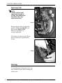
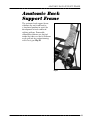
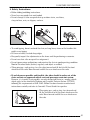
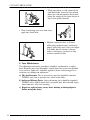
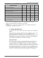
ENGLISH
User’s Guide
Scout
Mobile Positioning Chairs
READ INSTRUCTIONS BEFORE USING
SAVE THIS BOOK FOR FUTURE REFERENCE
CONVAID USER’S GUIDE
Customer Service Support
Toll Free: 1-888-Convaid (266-8243)
Phone: (310) 618-0111
Fax: (310) 618-8811
Email: [email protected]
International Email: [email protected]
Website: www.convaid.com
Technical assistance or repair information hours are:
Monday-Friday, 7 a.m. to 5 p.m. PST
Before Calling:
Please fill in the following. Customer Service will be
able to help you more quickly if the information
indicated below is readily available.
Serial number of chair:
Model of chair:
Date purchased:
Notice:
The information contained in this document is subject to change without notice.
No part of this document may be photocopied, reproduced, transmitted,
transcribed, stored in a retrieval system or translated to another language
or computer language, in any form or by any means, electronic, mechanical,
magnetic, optical, chemical, manual or otherwise without the prior written
consent of Convaid, Inc.
Use only Convaid accessories and parts on Convaid products. Convaid parts
are not interchangeable with other manufacturers’ products. Replace any
worn parts immediately.
© Copyright 2007 by Convaid, Inc. All rights reserved.
i
Table of Contents
Setting Up
Unpacking . . . . . . . . . . . . . . . . . . . . . . . . . . . . . . . . . . . . . . . . . . . . . 1
Unfolding . . . . . . . . . . . . . . . . . . . . . . . . . . . . . . . . . . . . . . . . . . . . . .1
Folding . . . . . . . . . . . . . . . . . . . . . . . . . . . . . . . . . . . . . . . . . . . . . . . 3
Fitting and
Positioning
Guide
Seat depth . . . . . . . . . . . . . . . . . . . . . . . . . . . . . . . . . . . . . . . . . . . . .5
Seat back height . . . . . . . . . . . . . . . . . . . . . . . . . . . . . . . . . . . . . . . . 6
Seat width. . . . . . . . . . . . . . . . . . . . . . . . . . . . . . . . . . . . . . . . . . . . . 6
Seat-to-back angle adjustment . . . . . . . . . . . . . . . . . . . . . . . . . . . . .7
Three-point positioning belt . . . . . . . . . . . . . . . . . . . . . . . . . . . . . . .7
Depth adjustable crotch strap . . . . . . . . . . . . . . . . . . . . . . . . . . . . . 8
Two-piece seat . . . . . . . . . . . . . . . . . . . . . . . . . . . . . . . . . . . . . . . . . 8
H-harness with padded covers . . . . . . . . . . . . . . . . . . . . . . . . . . . . 9
Footplate adjustment . . . . . . . . . . . . . . . . . . . . . . . . . . . . . . . . . . . 10
Footplate depth adjustment . . . . . . . . . . . . . . . . . . . . . . . . . . . . . 11
Swing-away adjustable lateral support–single flap . . . . . . . . . . . .12
Swing-away adjustable lateral support–double flap . . . . . . . . . . .12
Full torso swing-away support vest . . . . . . . . . . . . . . . . . . . . . . . .13
Lateral thigh support (adductor) . . . . . . . . . . . . . . . . . . . . . . . . . 13
Medial thigh support (abductor) . . . . . . . . . . . . . . . . . . . . . . . . . 13
Custom seat cut-back 1” and 2” . . . . . . . . . . . . . . . . . . . . . . . . . . 14
Heavy-duty reinforced upholstery . . . . . . . . . . . . . . . . . . . . . . . . 14
Padded headwings. . . . . . . . . . . . . . . . . . . . . . . . . . . . . . . . . . . . . 14
Headrest extension . . . . . . . . . . . . . . . . . . . . . . . . . . . . . . . . . . . . 15
Foam wedge . . . . . . . . . . . . . . . . . . . . . . . . . . . . . . . . . . . . . . . . . . 15
Foot positioner . . . . . . . . . . . . . . . . . . . . . . . . . . . . . . . . . . . . . . . . 15
Accessories
Upper extremity support surface . . . . . . . . . . . . . . . . . . . . . . . . . 16
Headrest cover (canopy) . . . . . . . . . . . . . . . . . . . . . . . . . . . . . . . . 16
Grab bar . . . . . . . . . . . . . . . . . . . . . . . . . . . . . . . . . . . . . . . . . . . . . 17
Transit Models
Miscellaneous
Wheels
Bus transport models . . . . . . . . . . . . . . . . . . . . . . . . . . . . . . . . . . . 17
Anatomic Back
Anatomic back support frame . . . . . . . . . . . . . . . . . . . . . . . . . . . . 28
Important
Information
Operating and safety instructions . . . . . . . . . . . . . . . . . . . . . . . . . 29
Warranty . . . . . . . . . . . . . . . . . . . . . . . . . . . . . . . . . . . . . . Back cover
Fabric removal . . . . . . . . . . . . . . . . . . . . . . . . . . . . . . . . . . . . . . . . 19
Specifications . . . . . . . . . . . . . . . . . . . . . . . . . . . . . . . . . . . . . . . . . 20
Locking and unlocking . . . . . . . . . . . . . . . . . . . . . . . . . . . . . . . . . . 21
Caster wheel lock . . . . . . . . . . . . . . . . . . . . . . . . . . . . . . . . . . . . . . 21
Wheel lock adjustment . . . . . . . . . . . . . . . . . . . . . . . . . . . . . . . . . 22
Anti-shimmy . . . . . . . . . . . . . . . . . . . . . . . . . . . . . . . . . . . . . . . . . . 22
Hand brakes . . . . . . . . . . . . . . . . . . . . . . . . . . . . . . . . . . . . . . . . . . .23
ii
CONVAID USER’S GUIDE
Setting Up
Unpacking
Check to see that the following items are included with the chair:
• Left and right footplates.
• Accessories as ordered.
• Hex wrench (5/32”, 3/32”).
Unfolding
SIZE / MODEL
CHART
Fig.1
Scout
Size
Model No.
12”
14”
16”
18”
SC12
SC14
SC16
SC18
Fig.2
1. Lay chair down with seat facing
upward. Fig.1
2. Unlock closure strap. Fig.2
3. Stand chair on front wheels. Fig.3
4. Grasp one handle and push down
on the seat tube. Fig.4
5. Press down firmly on seat tubes
to ensure the chair is completely
unfolded. Fig.5
Fig.3
Fig.4
Fig.5
1
SETTING UP
6. Use foot to lock the lower rear brace
into a straight position. Fig.6
7. Swing footplates and armrests down
into place. Fig.7 & 8
8. To keep closure strap from tangling
in the wheel, velcro it onto itself.
Fig.9
9. Apply wheel locks before placing
individual into chair. Fig.10
Fig.6
Fig.8
Fig.7
Fig.9
Fig.10
2
CONVAID USER’S GUIDE
Folding
1. Before folding, front wheels
of chair should be in trailing
position for best results.
Fig.11
Fig.11 Trailing
2. Release Velcro® on closure
strap. Fig.12
3. Unlock rear brace by
pushing up on center of
brace with foot. Fig.13
Fig.12
!
Caution:
Keep fingers
free of folding
mechanism.
Fig.13
3
SETTING UP
4. Flip up armrests and swing footrests to the side Fig.14. Grasp one
handle and with other hand pull up on seat fabric. Fig.15
Fig.14
Fig.15
5. Lay chair flat with seat facing upward. Push on seat tubes
or footplates to complete fold. Fig.16 & Fig.17
6. Move buckle on closure strap to appropriate length, wrap it
securely around chair and lock. Fig.18
7. With a straight back, bend knees and lift chair as shown. Fig.19
Fig.16
Fig.17
Fig.18
Fig.19
4
CONVAID USER’S GUIDE
Fitting Guide
Correct seating and positioning encourages good posture, which in
turn aids circulation, breathing and digestion. Please take the time
to properly adjust the chair to fit the user. If the user is not correctly
positioned, check the accessories section of this manual to see if one
or more of our accessories would help to facilitate posture or consult a
physical therapist. Improper seating can cause posture problems.
Please consult a physical therapist or doctor for additional guidance.
When properly fitted, Convaid chairs will provide years of comfortable
use. As the user grows, refer back to this Fitting Guide to adjust the
dimensions of the chair.
Seat Depth
Measure from the most
posterior portion of the
buttocks to the back of
the knee. Subtract from
that measurement 1-2” to
allow adequate clearance
between the seat and the
back of the knee. Fig.20
To change seat depth, partially fold
the chair to relieve fabric tension.
Undo the Velcro® back panel of the
two-piece seat. Grasp end of seat
tube, depress spring button and move
seat tube until spring button relocates
into the desired hole. Repeat for other
side of seat. Fig.21
pth
de
at
e
S
Fig.20
5
Fig.21
FITTING GUIDE
Seat back height
Seat Back Height
Seat back height varies according to chair size. Headrest
extensions are available when extra height is needed to support the head.
To determine the seat back height, measure from the seat to
the upper part of the head. Fig.22
Fig.22
Seat Width
Proper seat width enables the user to sit comfortably and
prevents problems from developing. While user is seated on
a flat surface, measure from hip to hip. Fig.23
The user should have enough room to prevent hips and
thighs from rubbing against the frame. However, the chair
should not be too wide or the user will slide around and
posture could be affected.
The seat width
measurement is taken
from the inside of the
armrest tubes. Fig.24
Fig.23
Fig.24
6
CONVAID USER’S GUIDE
Seat-to-Back Angle Adjustment
Depending on the user’s degree of ability or prescription from a doctor or physical therapist, the
back angle may need adjustment. Adjusting the
back angle may also affect the seat depth.
Partially fold chair to relieve fabric tension (see
folding instructions on page 3). Unhook the
Velcro® strip at the back of the chair connecting
the seat fabric to the back fabric. Use a wrench
(7/16”) to remove the bolt connecting the seat
tube to the back tube. Relocate to desired position and replace bolt. Repeat on other side.
Reattach the Velcro® strip. Fig.25
Seat-to-back angle:
85° - first hole (lower)
90° - second hole
95° - third hole
Fig.25
Three-Point Positioning Belt
The three-point pelvic positioning belt adjusts to keep the user
securely in position, and comes standard on the chair.
The positioning belt consists of two adjustable side straps, a
three-point quick-release buckle, and a depth adjustable crotch strap.
The three-point buckle is the connecting point for both side straps
and the crotch strap. The side straps are mounted to each side of the
frame and connect via clasps inserted into the sides of the buckle.
The crotch strap is attached to both the seat and the bottom of
the buckle.
To Buckle:
Insert the clasps into the
side of the buckle. Adjust
belt for a comfortable and
secure fit. Fig.26
To Release:
Press the red button on the
black buckle and pull out
the clasps.
Fig.26
7
FITTING GUIDE
Depth Adjustable Crotch Strap
The crotch strap can be
adjusted by threading strap
through desired slot. Fig.27
Fig.27
Two-piece Seat
The lower seat panel is
attached to the back panel
with Velcro®. It is used to
take up slack in the seat
panel after seat depth
adjustments have been
made. Fig.28, 29 & 30
Fig.28
Wrong
Excessive Velcro® overlap lifts seat fabric and
pushes hips forward,
creating poor
posture and
reducing
effective
seat depth.
Right
Correct Velcro® adjustment
provides room
for hips,
and makes
greater use
of seat
depth.
Fig.29
Reduced
seat
depth
Fig.30
8
CONVAID USER’S GUIDE
H-Harness with Padded Covers
H-harness shoulder straps help the user retain upright trunk position.
To adjust, insert the bolt at the end of the strap through the grommet
hole in the seat back. Grommet choice should be level with or higher
than the top of the shoulders. Choose a hole that will keep the user
secure without the strap rubbing against the face or neck. Secure the
strap with the threaded knob. Fig.31
Fig.31
Velour-covered shoulder
pads for the H-harness are
standard. The pads come
equipped with Velcro® for
easy attachment. Fig.32
Fig.32
9
FITTING GUIDE
Footplate Adjustment
Seat-to-footplate height is measured from the
back of the knee to the bottom of the heel.
Feet or heels should rest comfortably
on top of footplate. Fig.33
The Scout footplates are height
adjustable and swing away for access or
folding.
Fig.33
F
sup oot
he port
igh
t
Pull on ring to remove metal pin holding footplate in place. Move footplate
up or down, realign holes and replace
pin by pushing pin entirely through
holes in tube. Fig.34
In the event that the footplate height
adjustment described above is inadequate,
additional adjustments can be made
1. Pull out metal pin and remove the
footplate extension tube from the
frame. Fig.35
2. Press the spring button, then pull the
footplate assembly apart. Fig.36
3. Insert the footplate into the opposite
end of the footplate extension and
re-assemble. Fig.37
Fig.35
Fig.36
Fig.34
Fig.37
10
CONVAID USER’S GUIDE
For additional range:
4. Using a hex key (included), remove both bolts from the
housing bracket on the frame. Flip the bracket upside down and
replace bolts. Fig.38 & 39
5. Return the footplate extension tube to the housing bracket
and secure with metal pin. Fig.40
Fig.38
Fig.39
Fig.40
Footplate Depth Adjustment
All Scout models offer adjustable footplate depth.
Use a hex key to loosen the two bolts
located on the top of the footplate. Slide
footplate forward or aft to desired
depth. Retighten bolts. Fig.41
Fig.41
11
POSITIONING GUIDE
Positioning Guide
Convaid offers a wide variety of supports to help properly position the user.
Note: Convaid’s chairs provide a semi-contour fit around the body.
The user must be fitted correctly into the chair to achieve
optimal posture and comfort.
Swing-Away Adjustable
Lateral Support with Scoliosis Strap
Single
Flap
Adjustable trunk support stabilizes the trunk and maintains midline
positioning. It can be pulled to one side for scoliosis correction if
used with scoliosis strap. Scoliosis strap comes standard with all
trunk supports. Fig.42
Fig.42
Fig.43
The trunk support is attached to the chair with straps that wrap
behind the seat back and connect with Velcro®. Fig.43
Support is achieved by pulling each triangular flap toward the
appropriate side, then securing it by wrapping the strap around
the frame and attaching with Velcro®. The two flaps can also be
wrapped around the user’s torso and joined in the middle.
Double
Flap
One set of triangular flaps
locates the midline
positioning. The second
set of flaps wrap around
the trunk for stabilization.
The scoliosis strap can be
used to pull the torso to
either side. Fig.44
Fig.44
12
CONVAID USER’S GUIDE
Full Torso Swing-Away Support Vest
Adjustable support vest keeps user
in place comfortably and securely.
Helps maintain midline seating
position and prevent forward
slumping. The vest is attached to
the chair with straps that wrap
around the seat back and connect
with Velcro®, and shoulder straps
that screw into the seat back.
Adjust side straps for proper fit.
Fig.45
Fig.45
Lateral Thigh Support (Adductor)
Pulls thighs together, improving hip
alignment and stabilizing seating
position. Degree of adduction can be
varied and can favor one side. Fold
the adductor flaps over the thighs,
wrap the straps under and around
the armrest tube and attach the
buckle. Fig.46
The adductor is attached with
screws at the end of the seat tubes.
Fig.46
Medial Thigh Support (Abductor)
Separates thighs to improve hip
alignment and stabilize sitting
posture. Degree of abduction can be
varied and can favor one side. The
abductor flaps wrap over the user’s
thighs from the inside to the outside.
The straps can be buckled around
the seat tube or the armrest. They
can also be wrapped around the
armrest tube twice for
high-tone users. Fig.47
The abductor is attached with
screws at the end of the seat tubes.
13
Fig.47
POSITIONING GUIDE
Custom Seat Cutback - 1”and 2”
For the smaller individual,
a 1” (2.5 cm) or 2” (5 cm)
cutback seat may be more
comfortable and help
achieve proper seating. It is
available in standard or reinforced seat and must be
specially ordered. Fig.48
Fig.48
Heavy-Duty
Reinforced Upholstery
Heavy-duty, reinforced upholstery
is standard on the Scout. The
padded seat and seat back come
with pockets which have removable plastic stiffeners. Stiffeners
easily lift out of pockets for custom forming with a heat gun.
Fig.49
Fig.49
Padded Headwings
Adjustable padded headwings provide soft foam support for midline
positioning. Fig. 50 The padded headwings can be attached at any
height by wrapping the velcro straps around the frame and attaching
at the back of the chair. Secure the headwings by tying laces through
the grommet holes in the back of the seat fabric or headrest
extension. Fig. 51
Fig.50
Fig.51
14
CONVAID USER’S GUIDE
Headrest Extension
Headrest extension
fits easily into sockets
on seat back. Fold
chair slightly. Move
rubber grommets on
the mounting posts
to adjust height of
headrest extension.
Fig.52 & 53
Fig.52
Fig.53
Foam Wedge
Use wedge to modify
seating or positioning
or to correct posture.
Fig.54-57
Fig.54
Fig.55
Fig.56
Fig.57
Foot Positioner
To attach, thread
strap through
footplate as
shown in Fig.58,
then bolt strap
to underside of
footplate. Fig.59
Fig.58
15
Fig.59
ACCESSORIES
Accessories
Upper Extremity Support Surface
Tilt front of tray upward and
insert hook under the bolt or
the plastic knob. Lower the
tray so that the bent portion
of the support rod locks over
the armrest tube. Fig.60
Fig.60
Headrest Cover (Canopy)
1. Move rubber spacers to
adjust height of the canopy.
2. Insert into socket rod.
Fig.61
Note:
Partially
fold chair
before
installing
canopy.
Folding Canopy:
1. Peel back fringe of canopy.
2. Push down on pivot to
begin fold.
Fig.61
3. Complete fold. Release knob
and fold down metal rods.
16
CONVAID USER’S GUIDE
Grab Bar
Attach one end of grab
bar to the armrest tube.
Pull other end of
telescoping grab bar in
direction shown in
Fig.62 and attach.
(Grab bar not available
for SC16, SC18 and on
transit models.)
Fig.62
Transit Models
Fig.63
!
Caution: Convaid belts
and shoulder straps are
for positioning only and
are not to be used as a
vehicular restraint
17
Scout models have been crash tested and performed
satisfactorily at 30 mph / 20 g deceleration. Fig.63
Dummy weights as tested:
Scout
Model SC12T
66 lbs / 30 kg
Model SC14T
100 lbs / 45.5 kg
Model SC16T
170 lbs / 77 kg
Model SC18T
170 lbs / 77 kg
To reduce possibility of injury, the headrest
extension must always be used with the chair.
The following instructions should be followed to
duplicate test results:
1. Chair is to be forward facing with tray removed.
2. Use a tested, proven and compatible 4-point
wheelchair tiedown system and a 3-point
occupant restraint system in accordance with
SAE J2249.
TRANSIT MODELS
3. The wheelchair tiedown straps are to be securely attached from the vehicle floor
points to anchor points on the chair. All Convaid anchors are clearly identified by
their red color.
4. The occupant restraint system must include a lap belt anchored on the wheelchair
or on the wheelchair tiedowns, and a shoulder belt anchored to the vehicle
wall/roof and lap belt anchor point.
5. All floor tiedown straps must be tightened to eliminate any forward/aft movement
of chair.
6. Restraint manufacturers’ instructions are to be followed closely.
7. Tilt model chairs must be transported with the seat in an upright position, except
for medical necessity, when the maximum position must be within 30° of vertical.
Q’Straint
(954) 986-6665
5553 Ravenswood Road
Ft. Lauderdale, FL 33312
Ortho Safe Systems, Inc.
(609) 587-3859
PO Box 9435
Trenton, NJ 08650
Sure-Lok
(866) 787-3565
151 Industrial Prkwy.
Branchburg, NJ 08876
Unwin Safety Systems
(44) (01935) 410920
Willow House
Artillery Road
Yeovil, Somerset
BA22 2RP, U.K.
Q’Straint, Sure-Lok, Unwin and Ortho Safe specialize in crash-tested tie-down
systems and are in no way associated with Convaid, Inc.
18
CONVAID USER’S GUIDE
Miscellaneous
Fabric Removal
1. Partially fold the chair to relieve fabric tension
(see folding instructions on page 3).
2. Using a Philips screwdriver, remove the screw located at the end
of each seat tube. Fig.64
3. Loosen the four Velcro® straps located on the back of the chair. Fig.65
Fig.64
Fig.65
4. Unzip the four zippers located on the back of the chair. Fig.66
5. Lift fabric off seat tubes and away from upper handles.
The seat-reinforcing strap assembly should remain on frame. Fig.67
Fig.66
19
Fig.67
WHEELS
Wheels
Specifications
Scout wheels come standard with 8” and 12-1/2” pneumatic (air-filled) tires.
Fig.68 & 69
When ordering replacements, please have the following information available:
• Chair model and size
• Wheel size
• Tire type - ribbed or knobby
Pneumatic Tire Sizes:
Front Tire – Ribbed
Back Tire – Knobby
Size: 8”
Dimensions: 2” x 8”
Size: 12-1/2”
Dimensions: 2” x 12-1/2”
Fig.68
Fig.69
20
CONVAID USER’S GUIDE
Locking and Unlocking
Hand Wheel Locks
To lock, pull
down on
handle .
Fig.70
To unlock,
push forward
on handle.
Fig.71
Fig.70
Locked
Fig.71
Unlocked
Caster Locks
Caster locks hold swivel wheels in a forward-facing position to prevent
turning.
To Lock: With the wheels forward facing, press down on the button
located on the inside of the caster until the lock enters the hole in the
metal bracket on the wheel. Fig. 72
To Release: Press down on the lever located on the inside of the lock.
Fig. 73
Fig. 72
21
Fig. 73
WHEELS
Wheel Lock Adjustment
Set wheel locks to locked
position. Push chair with
light pressure on the rear
wheels. If wheel rotates,
adjust tension by turning the
adjustment nut until wheels
no longer rotate while
locked. Fig.74
!
Caution:
Wheel lock
adjustment
should be
inspected
periodically.
Fig.74
Anti-Shimmy
In the event that the
front wheels develop a
shimmy, use a wrench
(3/4”) to tighten the
stem nut. Adjust the
stem nut clockwise until
shimmy disappears.
Fig.75
Fig.75
22
CONVAID USER’S GUIDE
Hand Brakes
Use riding brakes to maintain control of
wheelchair when going down an incline.
A moderate squeeze to the two hand
levers will slow the chair, a firm squeeze
will stop the chair. Fig.76
Fig.76
When stationary, moving the handles to a
full rearward position will stop the chair
from moving. Fig.77
Fig.77
NOTE: Regular inspection is
necessary to maintain
brake system.
Follow the instructions in
the User’s Guide on how to
adjust brakes when needed.
Lever Adjustment
To increase brake pressure, turn adjusting nut (A) counter clockwise, then
turn locknut (B) clockwise to secure
nut (A) in position. Fig.78
B
Fig.78
A
23
WHEELS
Inner Pad Adjustment
Turn nut Fig.79 clockwise to move
pad closer to disk (wheel should
spin and not grab).
NOTE: Adjust when lever
pressure is too high.
Fig.79
Outer Pad Adjustment
Insert Hex wrench (2.5 mm) into
the screw Fig.80, turn clockwise
to move pad closer to disk (wheel
should spin and not grab).
Fig.80
Brake Pad Wear
Brake pads should wear no thinner than 1 mm
before replacement. Fig.81
1 mm
Fig.81
24
CONVAID USER’S GUIDE
Removal of Brake Pads
Remove calipers from the axle brackets
by unscrewing Hex bolts (A) & (B)
with a 5 mm wrench. Fig.82
B
Fig.82
A
Remove outer pad first by pulling tab
downward. Fig.83 To remove inner
pad, insert a 2.5 mm Hex wrench into
screw (A) Fig.84 and turn clockwise
until the back of the pad is clear of its
housing.
Clea
r Ho 1 mm
usin
g
A
Fig.83
Fig.84
With a small screwdriver (A), press the pad downward until it is clear of its housing. Fig.85 Remove the two springs from the old pad assembly. Fig.86 (A)
Attach the two springs to the new pad assembly making certain that the hooks are
properly seated over the two sheet metal steps. Fig.87
A
A
Fig.85
25
Fig.87
Fig.86
WHEELS
To install new pads, first insert inner pad
as shown Fig.88.
NOTE: Spring should lightly clip onto
the small post in the center of
the piston and push inward.
Fig.88
Using the 2.5 mm Hex wrench inserted
into (A), replace the pad into the
housing. At the same time, turning
anti-clockwise, insert a flathead
screwdriver to push the pad. Fig.89
A
Fig.89
Install outer pad by dropping the spring
side over the small post. Push upward
until the spring clips lightly onto the
post. Fig.90
Push Up
Fig.90
26
CONVAID USER’S GUIDE
Replacing Pads
NOTE:
A brake system needs
some time to break in.
Initially, the rubbbing of
the pad on disc may
cause some noise.
B
A
Fig.91
Return calipers to the axle bracket
using Hex bolts (A) and (B) and
Hex wrench. Fig.91 & 92
Make sure Hex bolts are
securely tightened.
Test brakes for effectiveness. Brake
levers should move approximately
25 mm.
Fig.92
Cleaning
To avoid damage to the brake seals, use
only alcohol or water when cleaning the
caliper parts.
27
ANATOMIC BACK SUPPORT FRAME
Anatomic Back
Support Frame
The anatomic back support frame
stabilizes the neck and head in
a functional position to assist the
development of neck-and-head
righting reflexes. Removable,
reformable stiffeners are located
inside the fabric seat back. Stiffeners
easily pull out for custom-forming
with a heat gun. Fig.93
Fig.93
28
CONVAID USER’S GUIDE
Important Information
Maintenance, Operating & Safety Instructions
• READ ALL INSTRUCTIONS BEFORE USING THE PRODUCT
• ALWAYS FOLLOW THESE SAFETY INSTRUCTIONS
• SAVE SAFETY INSTRUCTIONS FOR FUTURE REFERENCE
CAUTION: • For increased safety, the seat belt should be used at all times.
• Do not leave user unattended.
• Do not strap user too tight.
• Straps should not interfere with breathing or circulation
• Always apply wheel locks before letting go of the chair.
• If front edge of seat is at or forward of the point where tires
touch the floor, avoid using front of seat tubes for support
during entry or exit from chair to prevent tipping.
• Avoid using footplates for weight support during exit or entry
of the chair.
!
1. Waste Disposal
The shipping carton should be kept for possible return to the manufacturer/service facility
for repair or maintenance. Other paper packaging waste should be set aside for recycling.
For disposition of replaced parts or the complete chair, the materials should be separated
into: plastic, rubber, steel, aluminum, etc., and set aside for recycling.
2. Intended Use
This product is intended for use by a person with physical disabilities who is frequently or
permanently non-ambulatory. The chair is always under the control and supervision of an
attendant, and the occupant should never be left unattended.
3. Suitable Environment
The chair is intended for both indoor and outdoor use. If the chair is used in the rain, the
excess water should be wiped off with a soft cloth. If the chair is splashed with mud or
corrosive substances like salt water or road salt, the chair should be washed clean with
water, wiped dry and a hypoallergenic and biodegradable lubricant reapplied to the moving parts. The chair should never go into seawater, as it will corrode areas that cannot be
washed clean. When going from outside to inside, clean any excess dirt or mud from the
wheels to prevent soiling of inside environment.
29
CONSUMER INFORMATION
4. Safety Instructions
• Follow folding/unfolding instructions.
• Never leave occupied chair unattended.
• Do not attempt to take occupied chair up or down stairs, escalators,
steep inclines, or icy or slippery surfaces.
• To avoid tipping, do not overload the chair, or hang heavy items on the handles that
might cause tipping.
• Be aware of newly created sharp edges.
• Frequently inspect the adjustments on the frame and the positioning accessories.
• Do not use chair after occupant has outgrown it.
• Do not ignore minor malfunctions and maintain the chair in good operating condition.
Monitor the wheel locks (brakes) regularly and adjust as needed.
• When going up a curb or step, face the chair forward and tilt back to lift the front
wheels over the curb. Move forward and lift the rear wheels over the curb.
• If and whenever possible and feasible, the rider should transfer out of the
chair and into an approved vehicle seat and passenger restraint system.
However, if a transfer is not possible, use only designated chairs in a moving vehicle
which apply to the wheelchair Tiedown and Occupant Restrain System (WTORS)
following the requirements of SAE J2249. Follow tie-down harness manufacturer’s
instructions carefully and refer to Convaid’s ‘Transit Guide’ for specifics.
• When going up a curb or step, face forward and
tilt the chair back to lift the front wheels over the
curb. Move forward and lift the rear wheels over
the curb.
30
CONVAID USER’S GUIDE
• When going down a curb, approach the
curb backwards. Lower the rear wheels
down the curb and continue backwards,
taking the weight off the front wheels so
they can be gently lowered.
• When transferring user to or from chair,
apply foot wheel locks.
• Maintain control of chair at all times
while going up/down ramp. Avoid steep
slopes, particularly with a heavy occupant.
If in doubt, do not attempt a descent
unless a third party is present to help
maintain control of chair.
5. User Maintenance
The following maintenance procedures should be conducted on a regular
basis: Examine your Convaid product visually from time to time for possible
wear and tear. Lubricant* should be applied to frame and moving parts to
maintain easy folding and adjustment.
a) Tire Air Pressure: The air pressure in your tires should be checked
WEEKLY, since low air pressure may affect brake ability.
b) Axles and Moving Parts: Axles and moving parts should be wiped off
WEEKLY with a slightly moist cloth, to remove dust, dirt and mud. Apply
some lubricant* after each cleaning.
c) Repair or replace loose, worn, bent, missing or damaged parts
before using the chair!
31
CONSUMER INFORMATION
MAINTENANCE CHART
Rims, tires and tire pressure
Wheel locks and hand brakes
Accessories
Front and rear wheel axles
Cleaning & lubricating all moving parts
Belts, zippers and Velcro closures
Seat-/ back upholstery**/tautness
Armrests & foam
Frame
Weekly
Every 3
months
Every 6
months
As necessary
•
•
•
•
•
•
•
•
•
Contacting a Convaid representative
for service or repair***
•
* Use a non-toxic, hypoallergenic lubricant for all moving parts of the frame
** Follow cleaning instructions for appropriate user hygiene
*** NOTE: Repair or replacement of non-removable, worn or broken parts must be
performed by a qualified service facility.
6. Cleaning and disinfection
Clean all areas that come in contact with user or caregiver with a disinfectant
solution.
To prevent the spread of germs, disinfectant wipes should be used on a regular basis. Keep frame dry and apply a non-toxic, hypoallergenic and
biodegradable lubricant to all moving parts. After longer storage periods, and
before further use, the entire chair needs to be serviced, cleaned and disinfected. Follow the guidelines of each country and region.
Cleaning of frame:
Frame is to be kept dry and free of dirt and should be wiped off with a nontoxic, hypoallergenic and biodegradable lubricant. Lubricant should be
applied to moving parts as needed to maintain easy folding and adjustment.
All contact with salt water should be avoided. If the chair is used in salt-water
environments corrosion may occur. In the event of salt-water exposure, the
frame should be wiped off with a moist towel as soon as possible. Water and a
soft cloth are sufficient; lubricant should be reapplied to all moving parts.
32
CONVAID USER’S GUIDE
Cleaning of wheels and brakes:
Wheels should be kept free of dirt or mud so as to not interfere with pushing
the chair. The brakes are to be kept free of dirt or mud, so as not to interfere
with locking. Wipe wheels and brakes with a moist cloth as needed and readjust brakes if indicated.
Cleaning of fabric cover:
Seat and back upholstery can be easily removed, washed, air dried (a Phillips
head screwdriver is required) and reattached to the chair. Use standard
detergent to wash fabric.
Cushioned parts can also be removed from chair, washed or wipe off with a
moist cloth. Before reattaching them to the chair, make sure they are
completely dry. Use standard detergent to wash fabric.
Parts that are permanently attached may be wiped vigorously with a moist
cloth. Allow sufficient time to dry before placing user in chair.
7. Storage
Before extended storage periods, and before reuse, the entire chair needs to
be serviced, cleaned and disinfected.
8. Reuse
Your Convaid chair should undergo a wipe-down disinfection before reuse.
Please use a non-toxic, biodegradable disinfectant solution suitable for surface disinfection.
Please check the following components (see MAINTENANCE CHART) for
operation, intactness, etc. and replace if necessary:
• Wheels (tread pattern), air pressure if applicable
• Frame
• Seat- and back upholstery
• Wheel lock operation
• Bearings and axles: check wear and tear/ lubrication
• Straight-running stability of wheels
• Attachments
33
CONSUMER INFORMATION
9. Repairs
User: The user can replace easily removable parts or accessories, e.g. footplates and footrest assemblies, heel loops, all fabric items, hand grips, etc.
Manufacturer/Service Facility: Repair or replacement of permanently
attached, worn or broken parts must be performed by a qualified service facility. Any individual part of the chair can be replaced. If the service facility is
close, contact the manufacturer/service facility and the chair can be delivered
in person. Alternatively, after receiving a return authorization, the chair
should be packaged in the original or suitable shipping carton for return to the
manufacturer/service facility. Ship via parcel post or by private package delivery services.
10. Tools Required
User:
• 3⁄8”, 7⁄16”, 3⁄4” or 2 adjustable wrenches with 3⁄4” capacity Phillips head
screwdriver
• Hex key 5⁄32” (included)
Service Facility / Authorized Service Dealer
• A selection of imperial size wrenches, or two adjustable wrenches with
3⁄4”capacity.
• A Phillips head and a flat head screwdriver
• A rivet setting machine with a selection of tool sizes, or a set of hand tools
• Power drill with selection of imperial size drill bits
• Hex key 5⁄32” wrench (included)
11. Spare Parts
If the user is unable to visit a Service Facility to describe the problem, they
can request a diagram of the product be sent to them, so they can draw an
arrow to the part needing replacement. If not under warranty, they will
receive an estimate of the cost and, if necessary, shipping instructions for
return of the chair.
34
CONVAID USER’S GUIDE
12. Functional Tests
All four wheels should make contact with the floor. With the chair empty,
push it forward on a smooth level surface with enough momentum to travel
six feet (2 m). The chair should not veer to the left or right more than six
inches (15 cm). Wheels should be free running and the wheel locks (brakes)
adjusted to adequately secure the chair. Following the fold/unfold instructions, the chair should fold/unfold smoothly without undue effort. All fasteners should be secure. Fasteners on moving joints should not be over tight.
Seat fabric should not be wide-stretched or sagging. Positioning accessories
should be correctly adjusted and secure.
13. Authorized Service Dealer
35
Limited Warranty
Convaid warrants to the original retail purchaser of the Convaid product, that if any part
thereof proves functionally defective in material or workmanship within the specified
warranty period, such defective part will be repaired or replaced (at Convaid’s discretion)
free of charge. Warranty service may be performed by an authorized service center or
(at Convaid’s discretion) the factory.
Warranty Period
Frame & X-Braces.......................................Lifetime of original retail buyer
Other components ......................................One year
Fabric & webbing ........................................One year
This warranty does not cover normal wear and tear or damage caused by accident or misuse.
To exercise this limited warranty, the user should first obtain a Return Authorization Number from
Convaid’s customer service. The product must be delivered charges pre-paid (UPS recommended)
to the factory or to an authorized service center, together with a copy of the original invoice, the
Return Authorization Number and a written description of the problem.
THIS LIMITED WARRANTY EXCLUDES ANY CLAIM FOR INCIDENTAL OR CONSEQUENTIAL
DAMAGES. ANY IMPLIED WARRANTY APPLICABLE IS LIMITED TO THE DURATION OF THIS
WRITTEN WARRANTY. SOME STATES DO NOT ALLOW THE EXCLUSION OR LIMITATIONS OF
INCIDENTAL OR CONSEQUENTIAL DAMAGES OR LIMITATIONS ON HOW LONG AN IMPLIED
WARRANTY LASTS, SO THE ABOVE LIMITATIONS OR EXCLUSIONS MAY NOT APPLY TO THE
USER. THERE ARE NO WARRANTIES WHICH EXTEND BEYOND THE DESCRIPTION ON THE
FACE THEREOF.
This warranty gives the user specific legal rights and the user may have other rights that vary from
state to state. Warranty applicable in the USA only. May vary in other countries.
FAST FACTORY SERVICE: If being without the chair creates a hardship, the user may wish to
take advantage of our Fast Factory Service, whether under warranty or not.
WARRANTY REPAIR: Simply send the chair to Convaid by UPS Next Day Air (prepaid).
It will be fixed and shipped out within 48 hours by UPS Next Day Air at Convaid’s expense.
NON-WARRANTY REPAIR: The time to repair and ship the chair back to the user will be extended
by the length of time it takes to reach the user for approval of estimated repair costs.
The CE Mark Authorized Representative is Medical Specialties Ltd, Whalley BB7 9UE, UK
PO Box 4209, Palos Verdes, CA 90274
Toll free in the US: 1-888-CONVAID (266-8243) • Phone: (310) 618-0111 • Fax: (310) 618-8811
Email: [email protected] • International Email: [email protected]
Website: www.convaid.com
08/2007