1
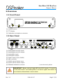
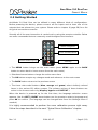
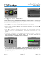
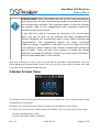
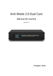
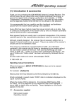
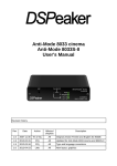
Anti-Mode 2.0 Dual Core Owner's Manual Recycling information The product you have purchased is marked according to the Waste Electrical and Electronic Equipment Directive (WEEE Directive). There are take-back systems in place that help to preserve nature and natural resources when products are disposed of appropriately. If you need to dispose of this product, use the take-back system that has dedicated collection facilities for electronic equipment. Do not put the product into household waste disposal! Also, the product has been manufactured using parts and processes that follow the directive of the Restriction of the use of certain Hazardous Substances in Electrical and Electronic Equipment (RoHS). Intended Use This product has been designed for normal indoor use and to be connected to other equipment with cables not exceeding 3m (10 feet) in length. If you use cables of extended length, check that their quality is sufficient and observe electrostatic discharge precautions when connecting or disconnecting them. Use of the device outdoors, in humid or other extreme environments, may cause reduced performance or risks to the user of the equipment. ANTI-MODE 2.0 DUALCORE OWNER'S MANUAL Table of Contents 1.Introduction......................................................................................................4 1.1 What's included in the box..................................................................................4 2.Overview..........................................................................................................5 2.1 2.2 2.3 2.4 Front Panel........................................................................................................... 5 Rear Panel........................................................................................................... 5 Getting Started.................................................................................................... 6 Typical Room Calibration..................................................................................... 7 3.Home Screen View..........................................................................................10 4.Settings Menu.................................................................................................12 4.1 House Curve Tool.............................................................................................. 13 4.2 Tilt Curve Tool................................................................................................... 14 4.3 Infrasonic Filter................................................................................................. 15 4.4 High/Lowpass filters.......................................................................................... 16 4.5 Custom Parametric Equalizers..........................................................................16 4.6 Homescreen and QuickTone.............................................................................19 4.7 Audio Settings.................................................................................................. 20 4.8 Input Settings................................................................................................... 21 4.9 Language Selection.......................................................................................... 22 4.10 Factory Reset.................................................................................................. 22 4.11 Information..................................................................................................... 22 4.12 PC Link............................................................................................................ 22 5.Using Sound Profiles.......................................................................................23 6.Advanced Calibration......................................................................................24 7.Multi-point (Wide Area) Calibration.................................................................25 8.Room Response menu (Measurements).........................................................26 9.Audio Connections..........................................................................................28 10.Troubleshooting............................................................................................29 11.Technical Specifications................................................................................32 11.1 Interfaces........................................................................................................ 32 11.2 Analog Specifications...................................................................................... 32 11.3 Firmware Specifications...................................................................................32 12.Contact.........................................................................................................32 Rev. 1.1 2014-03-07 Page 3 (32) ANTI-MODE 2.0 DUALCORE OWNER'S MANUAL 1.Introduction You are now in possession of a remarkable audio device capable of – no less than – making wonders to the sound quality of most audio systems. The list of the advanced features of the Anti-Mode 2.0 Dual Core is long; including jitterless digital output, audiophile-grade D/A converters with digitally controlled analog volume control, etc. But perhaps the most important feature, regrettably commonly overlooked by the industry, is the ability to correct the room resonances and other adverse effects generated by the listening environment. Perfection in sound can only be achieved through the mastery in the art of room acoustics! We have worked hard to ensure that the Anti-Mode 2.0 Dual Core is not only powerful and versatile but also intuitive and easy to use. However, it is a good idea to read this manual in whole before operating the unit. This manual is for firmware version “Jun 6 2013” or newer. 1.1 What's included in the box ✔ The Anti-Mode 2.0 Dual Core ✔ A power supply unit suitable for your country / region ✔ A calibration microphone ✔ An infra-red remote controller ✔ A USB cable ✔ This owner's manual Rev. 1.1 2014-03-07 Page 4 (32) ANTI-MODE 2.0 DUALCORE OWNER'S MANUAL 2.Overview 2.1 Front Panel 1 3 2 (1) Infrared sensor (2) TFT display (3) Calibration microphone connector 2.2 Rear Panel 1 OUTPUT 2 3 4 5 6 9 7 8 (1) Analog balanced XLR input* (2) Analog balanced XLR output (3) Analog RCA input* (4) Analog RCA output (5) Power supply input (12VDC) (6) USB connector (7) S/PDIF optical Toslink input (8) S/PDIF optical Toslink output (9) DSPeaker datalink connector *) see the warning below. IMPORTANT: Never connect both RCA and XLR inputs (1) and (3) at the same time! The analog INPUT connector types are meant to be exclusive alternatives to each other. Rev. 1.1 2014-03-07 Page 5 (32) ANTI-MODE 2.0 DUALCORE OWNER'S MANUAL 2.3 Getting Started Anti-Mode 2.0 Dual Core can be utilized in many different kinds of configurations. Before powering the device, please connect all the inputs and at least one of the outputs that are relevant to your system. Please refer to chapter 9 (page 28) for a list of typical connection scenarios. Virtually all of the user interaction is carried out by using the remote controller. Below are some commands that are commonly used throughout the interface: Menu navigation Color-coded buttons Profile buttons (A-D) Standby ➢ The MENU button brings out the main menu (press MENU again or the BACK button to return back to home screen from the main menu) ➢ Directional arrow buttons change the active menu item ➢ The OK button accepts any changes made and advances to the next screen ➢ The BACK button returns to the previous screen ➢ The three color-coded buttons (blue, orange and green) select similarly colored items in the various EQ editor screens. The primary actions of these buttons are active in the home screen only (display, bypass and OUTPUT.) When the device is powered up for the first time, the language selection screen appears. Use the LEFT / RIGHT arrow buttons on the remote to select a language and press OK to confirm. (The language can be changed later from the Settings menu if needed.) It is highly recommended to perform the room calibration process right away. Follow the steps described in the next “Typical Room Calibration” chapter. Rev. 1.1 2014-03-07 Page 6 (32) ANTI-MODE 2.0 DUALCORE OWNER'S MANUAL MAIN MENU 2.0 CALIBRATION Multi-point Advanced Typical Calibration 2.4 Typical Room Calibration Typical calibration is the default process, where the listening room is analyzed and corrected automatically. The optimal frequency limit of the correction is automatically detected based on the room response. ➢ Press MENU on the remote controller. The main menu screen appears. ➢ Use the arrow buttons to highlight the Calibration menu item and press the OK button to select it. ➢ Press OK to accept the Typical calibration mode (The Advanced mode allows more options to choose from. That and Multi-point calibration will be described later in this manual.) ➢ The speaker configuration screen appears. Use the arrow buttons to select the option that best matches your speaker setup. If you are unsure, select the 2.0 Stereo configuration. Press OK to confirm the selection. PREPARE MIC CONFIGURATION MIN MAX S/PDIF OUTPUT 2.0 Stereo Volume OK ➢ The microphone check screen appears. At this point, plug in the provided calibration microphone to the microphone jack and position it at the primary listening spot. The microphone should be positioned at ear height, with no reflective surfaces near the tip and fixed in place. Rev. 1.1 2014-03-07 Page 7 (32) ANTI-MODE 2.0 DUALCORE OWNER'S MANUAL Do not hold the microphone or the microphone cable in your hand during the measurement! Rather find a secure position where the microphone stays intact throughout the whole calibration process. ➢ Make sure either analog or digital output is connected to powered speakers or subwoofers. If the analog output is used, a test tone should now be audible. ➢ If needed, press the OUTPUT button on the remote to change to digital output. Please consider the warning below prior to doing so. WARNING: In order to preserve the dynamic range, digital output signal is never scaled. Consequently, the digital output level is always at 0 dB (i.e. maximum.) When using the S/PDIF output, please be sure to adjust your amplifier's volume controls to a moderate level in order to avoid damaging your ears and/or your audio equipment! ➢ Use the arrow buttons or the VOL+ and VOL- buttons to adjust the calibration volume (analog output only). ➢ The field at the lower part of the screen displays ”Volume OK” when Anti-Mode detects a sufficient volume level for a reliable calibration. ➢ The provided volume indication is a recommendation, and it best works with speakers. Sometimes a lower volume level may be sufficient for accurate measurement. ➢ If you can't hear the test tone (hissing noise), please make sure the output is connected and the amplifiers or powered speakers are functioning properly. ➢ When you are ready to start the calibration process, press the OK button to proceed. FOR BEST RESULTS: When calibrating a subwoofer system: 0.2 Stereo, 0.2 Dual-Mono, or a single subwoofer, make sure that the built-in lowpass filters of the subwoofer(s) are bypassed or set to the highest cutoff frequency. You can restore the setting after calibration or use Dual Core's Lowpass Filter Tool. Rev. 1.1 2014-03-07 Page 8 (32) ANTI-MODE 2.0 DUALCORE OWNER'S MANUAL ➢ Depending on configuration, the calibration procedure may start with a speaker distance detection. If the distance detection is successful, room acoustic analysis begins immediately after it. ➢ During the acoustical analysis phase, Anti-Mode generates several frequency sweeps. After the first sweep, the initial room response graph is shown in red. ➢ It is normal that the analysis phase lasts several minutes. ➢ You can cancel the calibration process at any time by pressing the BACK button. This will revert the room correction parameters back to their previous calibration state. (However, possible new speaker delay values from the distance detection step stay in effect. Please note that this behavior may change in a future firmware revision.) ➢ Once the analysis phase is finished, the corrected room response is shown in black. The limit of the automatically corrected range is displayed with a vertical dashed bar. Press the OK button to dismiss the screen. ➢ Congratulations! Your system is now optimized for the most accurate sound. Press the MENU button (or the BACK button) to return from the main menu to the home screen. Rev. 1.1 2014-03-07 Page 9 (32) ANTI-MODE 2.0 DUALCORE OWNER'S MANUAL PLEASE NOTE: After Anti-Mode gets rid of the room resonances, one might find that the sound was generally improved but there's not enough bass anymore. One possible reason is that the listener has grown used to the exaggerated bass response previously caused by room resonances. If you feel the need to increase (or decrease) the overall bass level, you can do this e.g. by utilizing the Bass Compensation setting. Navigate into the settings menu, select Audio Settings and Compensation. This adjustment affects the entire corrected frequency range. It updates in real-time so you can listen to music (via Analog or Toslink inputs) and choose a subjectively preferred level of bass. There are also other means to shape the target response (including QuickTone, House Curve and custom EQ filters) that are described later in this manual. After the calibration is done, you can view before and after measurements from the Room Response (Measurement) menu. You can use the same menu to make and view your own room response measurements. 3.Home Screen View The default home screen view consists of three components. The currently active input is displayed at the center. Similarly, the currently active output is shown at the bottom of the screen. The top of the home screen shows state information. The icons are (from left to right): (1) Input sample rate (in kHz) (2) Input bit depth (when available) Rev. 1.1 2014-03-07 Page 10 (32) ANTI-MODE 2.0 DUALCORE OWNER'S MANUAL (3) House curve indicator (4) Tilt curve indicator (5) Lowpass or highpass indicator (6) Custom EQ indicator (7) Infrasonic filter indicator (8) Speaker configuration indicator (9) The Currently active sound profile (designations “A” to “D”). Press the corresponding button on the remote to select a new active sound profile. See the ”Using Sound Profiles” section for further information. ➢ Press the INPUT button on the remote to switch the active input (source). ➢ Press the OUTPUT (green-coded) button to switch between the digital and analog output modes. ➢ Press the BYPASS (orange-coded) button on the remote to toggle the room correction on and off. The background of the home screen turns red when Anti-Mode room correction is NOT active. ➢ Press the DISPLAY (blue-coded) button on the remote to toggle screen dimming. The dimmed mode is less obtrusive with much less information on display. Keep the DISPLAY button pressed for 2 seconds to turn off the display completely. ➢ Press the MENU key to enter main menu. ➢ By default, the arrow keys are bound to QuickTone actions: press UP / DOWN to adjust the bass, LEFT / RIGHT to adjust the treble. You can re-assign the arrow keys to various functions (QuickTone, input select and playback controls) using the Homescreen settings menu. QuickTone can be used to perform full-spectrum sonic adjustments conveniently from the home screen. This can be useful e.g. when the user wants to quickly compensate for too bright or subdued recordings. When QuickTone controls are used, the applied curve is briefly shown on the screen as a simplified shape of the target frequency response. You can adjust the curve between flat (no curve) and very strong curve using 1dB steps. Rev. 1.1 2014-03-07 Page 11 (32) ANTI-MODE 2.0 DUALCORE OWNER'S MANUAL 4.Settings Menu Access the Settings menu from the home screen by pressing the MENU button on the remote, using the arrow buttons to highlight Settings and pressing OK. Among other things, this menu contains powerful tools for customizing the sound signature. The House curve tool adjusts target curve for the low frequencies (bass). The Tilt curve tool adjusts target curve for the high frequencies (treble). Enable or disable the built-in infrasonic filter. Select between three most common cut-off frequencies (10 Hz, 15 Hz, and 20 Hz). The Custom parametric equalizer tool creates filters with freely adjustable center frequency, bandwidth and gain. Up to 16 independent filter slots are available. Only recommended for advanced users. Audio Settings modify channel balance, headroom, and dip compensation. Homescreen: Configure the arrow and OK button functions. Input Settings: this menu allows to adjust analog input sensitivity, volume trim, and the operation mode of the USB volume control. The Lowpass or highpass tool. Create lowpass or highpass filters with the desired characteristics. Two independent filter slots are available. Only recommended for advanced users. Language: Change the menu language. Factory reset: clear all data from the selected sound profiles (the Anti-Mode correction, custom settings etc.) Use with caution: this operation cannot be undone. System Info: Display firmware version and CPU usage information. PC link: export the measurements to a computer via USB or perform system update. System update requires separate software which is currently available for Windows only. Visit www.dspeaker.com for more information. Rev. 1.1 2014-03-07 Page 12 (32) ANTI-MODE 2.0 DUALCORE OWNER'S MANUAL PLEASE NOTE: Any changes made in the various EQ editors are generally not updated in real-time. In order to hear the difference in the sound output, accept the changes and close the corresponding editor by pressing OK on the remote controller. 4.1 House Curve Tool The House curve tool provides a method of changing the target curve of the bass response. The motivation behind a house curve is in the sensitivity of the human auditory system and the hearing threshold – in addition to personal preference, of course. When sound pressure level is low enough, we are no longer able to hear the lowest bass frequencies, some emphasis may be required. It is easy to add a boosting equalizer to the lower bass region using the house curve tool. Note: the QuickTone Bass, Tilt, and Loudness controls uses the house curve filter, overriding user settings. WARNING: As with any low-frequency boosting EQ, employing an engaging house curve must be done with caution. Excessive low frequency lifting may introduce clipping of the amplifier or even cause damage to the woofer. Add house curve boosting in small increments at a time. The parameters of the House Curve tool are: ✔ Tilt: Defines the frequency range of the low HOUSE CURVE frequency boost (the effect is illustrated on the screen). Adjust using the LEFT/RIGHT buttons or the blue-coded button. ✔ Lift: Defines the maximum boost in decibels (the effect is illustrated on the screen). Adjust using the UP/DOWN buttons or the orange-coded button. 20 TILT 3 30 50 LIFT 5 100 ENABLED ✔ Enabled: Enables or disables the applied house curve. Toggle with the green-coded button. Please note that modifying the parameter values will automatically enable this equalizer. Press the green button (followed by OK) to disable it again. Rev. 1.1 2014-03-07 Page 13 (32) ANTI-MODE 2.0 DUALCORE OWNER'S MANUAL EXAMPLE: Boosting the lower bass under 50Hz by about 3 dB How to do it step-by-step: ➢ Open main menu by pressing the MENU button on the remote controller. ➢ Navigate to the Settings menu using the arrow buttons and press OK to select it. ➢ Select the House Curve Tool using arrow buttons again (the first item on the upper row.) ➢ Press OK and the House Curve tool opens. Using the LEFT and RIGHT arrow buttons, set Tilt to 2 or 3. The approximated response is shown on the screen. ➢ Using UP and DOWN arrow buttons, set Lift to 3. ➢ Once ready press OK to apply the new house curve 4.2 Tilt Curve Tool The Tilt curve tool provides a method of changing the overall frequency response slope of the treble. The motivation behind a tilt curve is (along personal preference) to compensate differences in various recordings. One can, for example, make a profile with treble tilted down to tame too “bright“ recordings. Note: the QuickTone Treble, Tilt, and Loudness controls use the tilt curve filter, overriding user settings. The parameters of the tilt curve are: ✔ Freq: The transition frequency of the effect (illustrated on the screen). Adjust TILT CURVE using LEFT/RIGHT arrow buttons or the blue-coded button. ✔ Gain: Attenuation (negative values) or emphasis (positive values) of the selected band. Adjust using UP/DOWN arrow buttons or the orange-coded button. 20 50 100 200 F 1500 500 1k GAIN-3 2k 5k 10k ENABLED ✔ Enabled: Enables or disables the applied tilt curve. Please note that modifying the parameter values will automatically enable this effect. Press the green button (followed by OK) to disable it again. Rev. 1.1 2014-03-07 Page 14 (32) ANTI-MODE 2.0 DUALCORE OWNER'S MANUAL EXAMPLE: Adding a -3dB treble tilt-down above 5 kHz Background: Some recordings seem too bright or 'toppy' in their tonal balance. To compensate this the high frequencies can be toned down using a subtle high frequency attenuation filter. How to do it step-by-step: ➢ Open main menu by pressing the MENU button. ➢ Navigate to the Settings menu using the arrow buttons and press OK to select it. ➢ Select the Tilt Curve using the arrow buttons again (the first element on the lower row.) Press OK to open the Tilt Curve tool. ➢ Now you can adjust the pivot frequency using LEFT/RIGHT arrow buttons, until the value is 5000Hz. ➢ Use the UP/DOWN buttons to set attenuation to -3dB. You can see the approximated frequency response of the filter on the screen. ➢ To save the filter, press OK. ➢ At any time, you can disable the tilt curve by opening the Tilt Curve tool again and pressing the green-coded button to disable the effect, followed by OK to apply the changes. 4.3 Infrasonic Filter The Infrasonic filter tool is a quick way to apply a subsonic highpass filter that filters out the signals below the audible band. The motivation behind an Infrasonic filter is to protect the woofer cones and to eliminate the effect of infrasonic harmonics and/or inter-modulation distortion. It is recommended to use an infrasonic filter whenever excessive house curve or low frequency boosting parametric equalizers are applied. The controls of the infrasonic filter are: ✔ Frequency: The frequencies below this threshold are attenuated. ✔ Enabled: Enables or disables the infrasonic filter. Use the arrow buttons on the remote controller to change the parameters. Press the OK button to store settings or the BACK button to cancel. Note: You can also design a custom infrasonic filter with the Lowpass/Highpass tool, which gives more control over the parameters (see High/Lowpass filters section below.) Rev. 1.1 2014-03-07 Page 15 (32) ANTI-MODE 2.0 DUALCORE OWNER'S MANUAL 4.4 High/Lowpass filters Anti-Mode 2.0 Dual Core features fully customizable highpass and lowpass filters. These filters can be used to control the pass-band of the speaker or subwoofer. For example, with a custom lowpass, it is easy to implement a more precise digital crossover filter for a subwoofer. A custom highpass filter can be used to attenuate lower frequencies and thus prevent them from reaching the main speakers. To design a custom lowpass or highpass filter, navigate into the Highpass/lowpass section of the Settings menu. Note that you can design two independent filters by selecting a different filter slot (use the LEFT/RIGHT arrow buttons to highlight a slot and press the OK button to accept). This allows you to design extremely steep lowpass or highpass filters, for example duplicating a maximally steep filter results in 48 dB / octave slope. The controls of the high/lowpass filter tool are: ✔ Frequency: the cut-off frequency of the filter, at which point the signal is attenuated exactly 6 dB. Activate with the blue-coded button, adjust with the LEFT/RIGHT arrow buttons (coarse) and UP/DOWN (fine). ✔ Slope: the steepness of the filter (6, 12, 18, or 24 dB / octave). Cycle with the orange-coded button. ✔ Settings: open the settings submenu. Settings submenu: ✔ Channel: selects the filter to apply to both channels, or just left or right channel. Use the LEFT/RIGHT arrow buttons to change the selection. ✔ Type: selects the filter type: highpass or lowpass. Use the LEFT/RIGHT arrow buttons to change the selection. ✔ On/off: enables or disables the filter. Use the LEFT/RIGHT arrow buttons to enable or disable. 4.5 Custom Parametric Equalizers The Custom Parametric Equalizers (PEQs) are very versatile filter structures that can implement a wide range of different bandstop, bandpass, highpass and lowpass filters. All user-defined parametric EQs are organized in 16 filter slots. The first step of the Parametric EQ tool is the filter list screen. Use the arrow buttons to highlight an Rev. 1.1 2014-03-07 Page 16 (32) ANTI-MODE 2.0 DUALCORE OWNER'S MANUAL inactive filter to create a new custom filter, or select an existing filter to change its parameters, then press the OK button to accept the selection. Note that there are more slots than the 6 visible ones, just scroll down with the DOWN button. Active filters are represented with green boxes in the filter list, inactive filters are grayed out. The filter name (such as EQ01S) gives general information about the designed filter. The number after the EQ refers to the number of the filter slot (ranging from 01 to 16). The arrow points either up or down to indicate its CPU usage: high or low, respectively. The last letter indicates whether the filter is stereo (“S”), left channel only (“L”) or right channel only (“R”). After selecting a filter to edit, the filter overview screen appears. An approximated response of the filter is displayed. The following actions are available: ✔ Edit: activates the edit mode (see below). ✔ Filter name: the filter slot of the current PEQ. ✔ Settings: Opens the settings submenu. Edit mode controls are: ✔ Center Frequency: the frequency at which the filtering effect is applied. Adjust with LEFT/RIGHT arrow buttons (coarse) and UP/DOWN buttons (fine) ✔ Bandwidth: approximately the 3 dB bandwidth of the effective band. This is equal to setting the Q value of the filter, but for simplicity user can adjust the bandwidth instead of the Q-value. (Q-value = Fc / Bw). Adjust with LEFT/RIGHT arrow buttons (coarse) and UP/DOWN buttons (fine). ✔ Gain: filter gain in decibels. The value is negative for a cutting PEQ (bandstop) and positive for a boosting (peaking) PEQ. Press the OK button (or the BACK button) to return to filter overview. Options in the settings submenu: ✔ Channel: Defines the channel this filter is associated with (left, right, or both). ✔ On/off: Enables or disables the designed filter. Press the OK button (or the BACK button) to return to filter overview. Press the OK button to accept any changes, close overview and return to the filter list. Use the BACK button to discard any changes made. Please note that any new filters or edits will not affect the sound audibly until the filter list is closed. Rev. 1.1 2014-03-07 Page 17 (32) ANTI-MODE 2.0 DUALCORE OWNER'S MANUAL EXAMPLE: Adding a psycho-acoustic 3 kHz dip Background: The idea behind the 3 kHz dip originates from the human auditory system and diffuse field characteristics. The human hearing is less sensitive to diffuse fields in the neighborhood of 3 kHz. Because of a flat microphone response, many recordings have too much energy around the 3 kHz region, compared to the original listening situation (e.g. in a concert hall). A cutting PEQ at 3 kHz can be introduced to compensate. Whether or not this is beneficial is left to be judged by the user. This example shows how to create the cutting PEQ (or any other parametric equalizer). How to do it step-by-step: ➢ Open the menu display by pressing the MENU button ➢ Navigate to the “Settings” menu using the arrow buttons and press OK to select it ➢ In the settings menu, select the “Parametric EQ” using the arrow buttons. (The second element on the lower row.) Press OK to proceed. The Parametric EQ filter list appears. ➢ First you need to assign a filter slot for the filter. If there are no previously designed Parametric EQ filters, the first slot is automatically selected and you only need to press OK to proceed to the PEQ designer. ➢ At the filter overview, open the “EDIT” submenu by pressing the bluecoded button on the remote controller. ➢ Adjust the center frequency to 3000Hz by pressing the arrow buttons. (You can press and hold the buttons to adjust faster.) ➢ Press the orange-coded button to activate the bandwidth adjustment. Using the arrow keys set the bandwidth to about 1000 Hz. ➢ Press the green-coded button to adjust the filter gain. Using UP/DOWN for +/- 0.1dB adjustments and LEFT/RIGHT for +/- 0.5dB, set the gain to -4.2dB. ➢ The custom equalizer is now ready. Save it by pressing OK twice. You are returned to the filter list. The designed filter gets enabled when you go back to the settings menu by pressing the BACK button. ➢ Now you can try out how the psycho-acoustic dip works for you. You can also fine-tune the parameters and try to find out if there is a setting that suits your ears the best. Rev. 1.1 2014-03-07 Page 18 (32) ANTI-MODE 2.0 DUALCORE OWNER'S MANUAL 4.6 Homescreen and QuickTone The Homescreen menu configures the operation of the arrow and OK buttons when the home screen is visible. QuickTone controls offer a quick and easy way to adjust bass and treble. The default assignment for the arrow buttons are UP/DOWN for bass and LEFT/RIGHT for treble. HOMESCREEN KEYS Up/Down Left/Right OK: Play To configure the OK button, select the bottom entry and use LEFT and RIGHT arrow keys to switch between Menu and Play. The former allows the OK button to bring up the menu (default), the latter changes the OK button to act as a Play / Pause button in the USB mode. You can assign functions to the UP / DOWN and LEFT / RIGHT arrow buttons by selecting a pair using the UP / DOWN buttons, then pressing OK. An array of options appear. Highlight the option you want to assign, then press OK to select. The options are: 1. OFF : no function assigned 2. TILT : tilt the full spectrum (bass down and treble up, or bass up and treble down) 3. BASS : adjust bass (0 to 6 dB) – default for the UP/DOWN buttons 4. TREBLE : adjust treble (-6 to 6 dB) – default for the LEFT/RIGHT buttons 5. LOUDNESS : adjust loudness curve (bass up and treble up) 6. INPUT : switch to next/previous input (no need to cycle though all of them) 7. PRV/NEXT : skip to previous and next track in USB mode. The media player software used on the PC needs to support the USB HID commands (Prev/Next) for these buttons to work. By assigning Tilt, Bass, Treble, or Loudness you can quickly perform full-spectrum sonic adjustments from the home screen. Please note: QuickTone operates by activating the filters of the House Curve and Tilt curve tools. This means it will override any settings previously made on them. When adjusting only bass or only treble, the other remains unchanged. Rev. 1.1 2014-03-07 Page 19 (32) ANTI-MODE 2.0 DUALCORE OWNER'S MANUAL 4.7 Audio Settings Audio settings can be configured from this menu. CHANNEL BALANCE AUDIO SETTINGS Ch. Balance Headroom Compensation L DIGITAL HEADROOM R 00.0 dB Close Min Max 00.0 dB Close Use the manual channel balance adjustment to match the levels of the left and right speakers. Changes in this dialog take effect immediately. Press the OK button on the remote to accept the new adjustment or press the BACK button to discard changes. All internal processing is performed with 32- or 40-bit accuracy with the appropriate number of bits reserved for headroom. However, if emphasizing (amplifying) filters are used, some input signals could cause saturation / clipping at the output. The unit automatically calculates the best headroom setting from the gains of the active filters. However, if you only use the analog input and do not use the full input range, you can change the headroom setting to a lower value. If the automatically calculated value is too small (causing clipping at output), you can manually increase the headroom value. The headroom value is automatically re-calculated every time you calibrate or change filter settings, so remember to re-do your own adjustment as a last step in these cases. Compensation setting affects the overall bass level throughout the frequency range Anti-Mode calibration was performed on. This setting can also lift (compensate) dips residing in the area. Adjustment operates in real-time, so it is possible to look for a subjectively good value while listening to audio (via Analog or Toslink input). Also the BYPASS button on the remote is available in this screen. Notice: channel balance, headroom, and dip compensation values are associated with the current sound profile. 4.8 Input Settings Input settings can be configured from this menu. Rev. 1.1 2014-03-07 Page 20 (32) ANTI-MODE 2.0 DUALCORE OWNER'S MANUAL INPUT SETTINGS USB VOLUME CTRL VOLUME TRIM ANALOG USB Volume Volume Trim By Computer In-Sens: Low By Remote S/PDIF 00.0 dB Close USB Volume controller defines how the volume is controlled during USB audio mode. By Remote keeps the volume control in the hands of the user. In this mode the PC does not control the volume. By selecting By Computer you allow the PC to control the volume, and the volume control buttons are just reported to the PC through HID (human interface device). It is upto the PC to interpret the buttons and perform the appropriate action. Please note that selecting By Computer may cause a high volume to be set from the PC, so be careful in this mode, especially when you connect Dual Core to the PC for the first time. The Volume trim menu allows compensation of different volume levels between the digital and analog inputs. For example, if the digital input is subjectively louder, adjust the volume trim value towards the left side until the volume levels are equal. Changes in this dialog take effect immediately. Press the OK button on the remote to accept the new adjustment or press the BACK button to discard changes. The Input sensitivity setting adjusts the maximum allowed voltage level of the analog input. Default value is high sensitivity. Use the low sensitivity setting, if you connect a device which produces very high voltage levels (indicated by a clipping warning on the home screen). Notice: Input sensitivity and volume trim are global settings, i.e. the values are shared by all four sound profiles. 4.9 Language Selection ”Language” allows for changing the menu language. Currently available languages are English, Finnish, Swedish, Dutch, and German. More translations may be added in future firmware revisions. Rev. 1.1 2014-03-07 Page 21 (32) ANTI-MODE 2.0 DUALCORE OWNER'S MANUAL 4.10 Factory Reset The Factory reset menu lets you clear data stored on the active sound profile, or alternatively clear all user data stored on the device. Use with caution: this operation cannot be undone. 4.11 Information Use this menu to display firmware version, CPU usage information, and board revision. 4.12 PC Link By selecting “PC Link”, you can export the measurements of the currently selected profile to a PC or Macintosh computer via USB. In this mode, Anti-Mode 2.0 Dual Core will appear as a removable drive once connected to the computer. You can copy the measurement files (in ascii/text format) that can be imported to popular PC / MAC measurement programs. The measurement files are named accordingly to indicate the profile and the measurement type. ✔ ”a-after.txt” - the automatically generated response after the Anti-Mode room correction ✔ ”a-before.txt” - the automatically generated original room response without correction ✔ ”a-user1.txt” - the user-made measurement ✔ ”a-user2.txt” - the secondary user-made measurement In the above example, the default profile A was active. To export measurements stored in another sound profile, activate the corresponding profile before entering PC Link mode. The names of the files will change to reflect the profile, e.g. ”b-after.txt” etc. System update is also performed in the “PC Link” mode. The system update requires separate computer software which is currently available for Windows only. Visit www.dspeaker.com for more information. Rev. 1.1 2014-03-07 Page 22 (32) ANTI-MODE 2.0 DUALCORE OWNER'S MANUAL 5.Using Sound Profiles Anti-Mode 2.0 Dual Core supports up to four independent sound profiles. A sound profile includes everything that affects the sound: room correction filters and all possible custom filters – highpass/lowpass filters, house curve, tilt curve, and PEQs. Also all room measurements are stored in the profile. The profiles can be utilized for various things. For example, you can calibrate up to four different listening spots using a profile for each location and switch between the spots quickly and conveniently. Or, you can create separate equalizer presets for music listening and movie watching. The sound profiles can also be of assistance when comparing the effects of different custom filters. Initially, only one profile (A) is available. To create another, navigate to the Sound Profile dialog located in the Main Menu. Select this icon to create a new profile. The newly created profile will be identical to the currently active profile. The new profile will populate the first empty slot available. If all four profiles are in use, one of them must be deleted before a new profile can be created. Select this icon to delete the currently active profile. Please note that profile A cannot be deleted even if other profiles would still exist. After the new profile has been created, you can change its characteristics by starting the room calibration process or modifying one or more settings in the Settings menu. Note: if you wish to create an empty sound profile without inheriting any characteristics, you can use Factory Reset located in the Settings menu to clear the newly created profile from all previous data. Rev. 1.1 2014-03-07 Page 23 (32) ANTI-MODE 2.0 DUALCORE OWNER'S MANUAL 6.Advanced Calibration Advanced calibration gives the user more control over the calibration parameters. The procedure is similar to the typical calibration, but with some additional steps. Refer to ”Typical Calibration” section of this manual for an overview of the basic process. To perform the advanced calibration, choose the Advanced Calibration option at the Calibration menu. ➢ After choosing the relevant speaker configuration, the extra settings dialog will appear. Level compensation affects compensation for wide dips in the bass response. Compensation has three levels, “Off”, “Norm” and “Max”. If the setting is “Off”, no compensation to boost dips is applied, and the bass level remains as low as it would be without room effect. This gives maximum headroom for the user to design custom boosting filters, such as House Curve or Parametric EQs. The “norm” setting applies a mild compensation, which is the same amount that “Typical” calibration is using. This setting usually gives the best audible result as the perceived level of the bass is closer to the uncorrected average bass level than with the uncompensated “Off” setting. When selecting “Max”, maximum compensation is used, which gives about +2dB more gain for boosting filters. This setting is beneficial in spaces where part of the problem is the general lack of bass, possibly resulted by the absence of proper acoustic barriers. It is good to remember that destructive reflection nulls can not, will not, and should not be attempted to be corrected by any DSP. Note: you can also adjust the compensation level afterwards from the Compensation setting in the Audio Settings menu. ➢ Select the desired amount of compensation and press the OK button to proceed. ➢ The next dialog controls the time-alignment of channels. There are three possible options: Auto-detect, Off and Manual. It is advised to use the auto-detect for subwoofers and “Off” for the full-range speakers, as the full-range speakers are assumed to be equidistant from the listener. Note that optimal acoustic delay is not always the same as physical distance to the subwoofers: because of this the automatic detection is advised to be used always on subwoofers. If the manual setting is chosen, the compensation delay for each channel for subwoofers / speakers can be entered to the corresponding Rev. 1.1 2014-03-07 Page 24 (32) ANTI-MODE 2.0 DUALCORE OWNER'S MANUAL fields. The manual channel compensation delays are meant primarily for more complex systems, such as a 2.2 system with two Dual Cores or equivalent. In the Typical calibration, automatic detection of delay is always employed when calibrating two subwoofers (either stereo or dual-mono) but not in full-range 2.0 mode. You can still use time-alignment and auto-detect for the full-range 2.0 setup by choosing the Auto-detect option. The auto-detection always calculates compensation to produce the minimum lag, meaning it will only delay the channel that is “too early” compared to the other, whereas manual adjustment of the delays allows delaying both channels. This is of course unnecessary for any systems where all of the audio is going through Anti-Mode 2.0 Dual Core. ➢ Press the OK button to proceed to the next dialog. Now you can select the upper frequency limit of the automatic correction. Using the arrow buttons, set the upper limit of the correction between 80 and 500Hz. Bass signals have no directionality at the lowest frequencies, but they get directional toward the mid-range bass and above. Because of this, Anti-Mode 2.0 Dual Core employs correction of the summed output on lowest frequencies (where all audio material is essentially monophonic), but the correction becomes more channel-dependent towards lower mid-range and higher frequencies. After all it is a different concept to measure either left or right channels separately, compared to measuring both in-phase (which applies to the majority of any bass content). All this directionality versus summed (inphase) effects are automatically handled by Anti-Mode 2.0 Dual Core controlled by the selected correction frequency range. ➢ After selecting the desired settings, press OK button on the remote to proceed to the volume level check. From here on, the calibration process is similar to the Typical calibration described earlier. 7.Multi-point (Wide Area) Calibration The Anti-Mode 2.0 Dual Core features a wide area optimization method which allows for a larger ”sweet spot” to be corrected. Fortunately, wide area algorithm does not require you to measure dozens of different places around the listening area. In most cases it should be enough to make the main calibration in the center of the target listening area, and when it is complete, more points can be added to the calibration data. Rev. 1.1 2014-03-07 Page 25 (32) ANTI-MODE 2.0 DUALCORE OWNER'S MANUAL ➢ To perform a multi-point calibration, the first step is to calibrate the device normally, following either the Typical or Advanced procedure. ➢ After the first calibration, you can add more points by choosing the “Multi-point” option at the Calibration dialog. Place the microphone to one edge of the listening area and continue calibration. ➢ You can add as many points as you want to the calibration, and the system automatically weights them by comparing them to the main calibration data. The maximum recommended number of additional points is 7, more points would not contribute much to the correction model. Please note: if the listening area consists of rather two alternate areas, instead of one larger one, it is recommended to perform separate calibrations into two separate profiles. In other words, the alternative area is calibrated into another profile, and the user can then switch the optimum correction to one of the spots at a time. 8.Room Response menu (Measurements) The Room Response menu and measurement tool allows you to measure and view the response of currently active filters. You can also view the room responses measured during the automatic Anti-Mode calibration process. The calibration measurements always show the most important frequency range in terms of room correction – from 16 Hz to 200 Hz. The upper limit frequency of the calibration is shown as a dotted line on the display. PLEASE NOTE: Bass response measurements are always shown just as they were measured, without ”sugar coating”. No smoothing is applied to make things look prettier than they actually are. It is good to remember that small variations even in the corrected response are normal. Especially narrow dips are generally inaudible and can be ignored. Trying to pursue a “ruler flat” frequency response by any means is likely not going to produce an optimal result. Anti-Mode performs comprehensive time-domain acoucstic optimization -̶ a frequency response graph shows only one aspect of it. Rev. 1.1 2014-03-07 Page 26 (32) ANTI-MODE 2.0 DUALCORE OWNER'S MANUAL You can store up to eight custom measurements (two per sound profile). The frequency range can be the same as it is on before/after responses. However, sometimes it can be useful to measure the entire audio band instead. For example, a full-range measurement may be helpful when trying to find the optimal locations for acoustical treatments or when finding the perfect toe-in angle for the loudspeakers. Note that “Measurements” is not the same as “Calibration”. The Measurement tool simply makes measurements without applying any correction. To make a custom measurement, navigate to the Room Response (Measurements) in the Main menu. ➢ Highlight “Make New” and press the OK button. ➢ In the next menu, you can define the range of the measurement: bass (16Hz – 200Hz), bass-midrange (16-500Hz) or full-range (20Hz - 20000Hz). You can also select the target channel (left, right or both) to be measured. ➢ Remember to check that the microphone is connected. Once you are ready, you can start the measurement. With full-range measurements, the alignment of the microphone is more sensitive than with the bass-only measurements. The microphone should be pointing towards the ceiling. ➢ Once the first measurement is ready, a secondary measurement slot becomes available in the Measurements menu. This measurement has the same range as the first one, but you can select the channel(s) to measure. This enables you to, for example, compare a room response of the left channel to that of the right channel, compare the effects of the designed custom filters, different points within the listening zone and so on. ➢ By pressing LEFT/RIGHT arrow button you can activate a tracker cursor to view the exact frequency and magnitude value. Pressing UP/DOWN will move the cursor with a smaller step. (The frequency tracker feature is currently available for bass measurements only.) ➢ Close the measurement dialog with the OK button to store the measurement. ➢ Remember that each sound profile has its own measurement data. This way, with up to four profiles available, you can store a maximum of 8 custom measurements. This is in addition to the 4 ”before / after” responses of the Anti-Mode calibration measurements that are automatically generated. Rev. 1.1 2014-03-07 Page 27 (32) ANTI-MODE 2.0 DUALCORE OWNER'S MANUAL 9.Audio Connections Anti-Mode 2.0 Dual Core's connectivity allows building very different kinds of audio systems with it. Below are listed some of the most typical scenarios. You can find more examples from our website, www.dspeaker.com. ➢ Dual Core as a 2-channel pre-amplifier and DAC Connect audio sources to Dual Core's inputs. You can connect up to three sources using USB, Toslink (S/PDIF) and one of the analog inputs. External switchers and converters can be used to extend the number and types of connections. Connect Dual Core to your amplifier using the XLR or RCA outputs. ➢ Using Dual Core as a digital-only audio processor Connect audio sources to Toslink (and/or USB) inputs. Connect Toslink output to an external DAC. In this mode, Dual Core's volume control is not active. ➢ Using as an audio processor with integrated amplifier Use a DSP processor loop or tape monitor loop to connect Dual Core. If this is not possible, pick the audio source that most benefits from the room correction and insert Dual Core between that source and the amplifier. ➢ 2.1 or 2.2 system If you have a 2.1 or 2.2 system (main speakers with one or two subwoofers) with existing cross-over, connect Dual Core before the cross-over. Your system is then seen as a 2.0 full-range system by the Dual Core and both your main speakers and subwoofer(s) will be corrected. It is also possible to connect speakers and subwoofer(s) in parallel. In this case the combined response is measured and corrected by Dual Core. For optimal results, subwoofers' level and phase should be adjusted before calibration. ➢ Subwoofer configurations Select the appropriate configuration for your subwoofer set-up during the calibration process. If you connect more than two subwoofers, group them according to their location and how symmetric their placement is. For example, subwoofers in the front corners are more similar to each other than a subwoofer in a corner is to another subwoofer in the middle of a wall. Rev. 1.1 2014-03-07 Page 28 (32) ANTI-MODE 2.0 DUALCORE OWNER'S MANUAL 10.Troubleshooting ✗ The Dual Core does not remember my settings after power down: to ensure optimal use of the built-in non-volatile memory, common settings are stored only when entering stand-by mode. In other words, if you want to store settings such as default volume level, input volume trim etc, simply press the red stand-by button on the remote controller. After that, the Anti-Mode 2.0 Dual Core will remember the stored settings even after power down. ✗ Ambiguous delay: this error may occur at the beginning of the calibration process, if the distance / delay is not detected correctly. In most cases it happens either because of a bad placement of the microphone, or simply because of too low calibration volume compared to the ambient noise. The remedy is to move the microphone about 4 inches (10cm) away from the original place and making sure that there are no objects in the proximity of the microphone capsule. Also increasing the measurement volume is recommended unless the volume is already well beyond the “Volume OK” threshold. The distance / delay compensation values can also be inserted manually. The closer channel should be delayed by 1000*S/V [ms] where S is the difference in distances and V is the velocity of sound (340m/s or 1116 feet/s). For example, if the left speaker is 3 ft. closer than the right one, the compensation delay should be set to the left channel as 1000*3/1116 = 2.7ms and 0ms to the right channel. ✗ ”Clipping Detected”: this warning is displayed on the home screen in two cases. 1.”Clipping Detected” is shown when the Anti-Mode 2.0 Dual Core detects that the analog input signal has reached the maximum input voltage level, causing the input to be clipped. Check the output settings of the device you have connected to the Anti-Mode 2.0 Dual Core analog inputs. If you can not reduce its output level, set the input sensitivity to low in the ”Input Settings” menu. If this does not help, you can try using the RCA inputs instead of XLR inputs, or use external attenuators. 2.”Clipping Detected” is also shown when there is a possibility of clipping at the output stage, which could compromise audio quality. Usually the reason for this warning is that too many boosting equalizers are being employed. To overcome this, increase the digital headroom value located in the ”Audio Settings” menu. Sometimes also decreasing the input gain may help. Rev. 1.1 2014-03-07 Page 29 (32) ANTI-MODE 2.0 DUALCORE OWNER'S MANUAL ✗ No sound: Check the connections. Check that you have selected the correct input (ANALOG, USB, or S/PDIF). Use the INPUT button on the remote controller to select the correct input. Check that mute is not active and that the volume level is not too low. Check that you have the correct output. Use the OUTPUT button on the remote controller to switch between the analog (RCA and XLR) and digital (S/PDIF Toslink) outputs. Note that you can use the room measurement's level check tool to generate noise and confirm that the output is functioning. ✗ No sound / bad sound from S/PDIF digital input: In addition to the above, check the digital signal format of the audio source. Only PCM input is accepted, compressed formats are not supported. Please note that the Anti-Mode 2.0 Dual Core does not accept 192 kHz sampling rate. Check that you have the latest firmware. Note: when using the USB input, the PC decodes any compressed format before passing the audio in PCM format to the Anti-Mode 2.0 Dual Core. ✗ Not enough bass after calibration: a rather common first impression after listening to years of resonance-infested bass. You slowly get used to the missing resonances, but if the bass level is still too low, use the following methods. If your system has subwoofers, their volume can be adjusted after the calibration. With loudspeakers (as well as on subwoofers) you can use the House Curve or Parametric filter tool to increase the bass to match the preferred level and tone. You can also adjust the dip compensation value from the Audio Settings menu. ✗ Custom filters get disabled: this can happen for two main reasons. First of all, when you start the calibration, all filters are disabled automatically. Even if you cancel the calibration before a new room correction is applied, the disabled filters are not activated with the exception of infrasonic and high/lowpass filters. The filter designs do not vanish, however. You can simply re-enable them after the calibration. Another possible reason is running out of computational resources. Even though Anti-Mode 2.0 is equipped with two very powerful processors, even their capacity is not infinite. If too many complex filter structures would exceed the CPU limit, the system automatically disables one or more of the least significant filters to not exceed the available resources. ✗ Problems with room correction are usually ultimately caused by a bad room calibration analysis. The single most important factor for successful room analysis is to make sure that the calibration volume is sufficiently high. Sometimes the automatic level detection may indicate “Volume OK” even when it is in fact too low. Rev. 1.1 2014-03-07 Page 30 (32) ANTI-MODE 2.0 DUALCORE OWNER'S MANUAL This can occur especially in noisy environments and/or with limited band subwoofers. When calibrating a subwoofer system, always disable subwoofer's integrated low-pass filters or set them to their maximum cut-off frequency. You can enable them after the calibration process, or utilize Dual Core's digital precision lowpass filters that are probably more adjustable and capable. It is also important to try to avoid all other cables running along the microphone cable, as they might induce errors through the microphone shielding. Make sure you do not open or close doors during calibration, as they tend to have much greater impact to the room response than expected. After these checks, recalibrate and verify that the before / after graphs are looking good. If the problems persists, contact DSPeaker support. It speeds up the troubleshooting process if you have a picture taken of the before / after graphs (with a camera) or have exported the responses to a file using USB. ✗ Volume jumps each time USB is selected If you have selected USB Volume: By Computer in the Input Settings menu, when you select USB, your PC sets the last volume setting it has previously used with the device. That setting is restored each time USB input mode is selected while the unit is attached. With the By Computer mode the VOL+ and VOL- buttons are reported to the PC, which performs the volume control operation. You can also adjust the volume using the master volume control on the PC. If you select USB Volume: By Remote in the Input Settings menu, volume control from the PC is ignored, and VOL+ and VOL- buttons adjust the volume directly. Mute can still be controlled by the PC. Be aware that volume controls in an audio or multimedia player program may use digital volume control, which causes the digital data to be scaled. So check that you use master volume. Using the master volume control does not cause any precision to be lost, because it controls the analog volume at the output of the Dual Core. ✗ The Anti-Mode 2.0 Dual Core does not show up in USB The unit will only act as a USB device when the USB audio input is selected, or when you have selected the PC Link option from the Settings menu. In the former case you will get standard USB Audio device (asynchronous mode) and human interface device (some of the buttons in the remote controller are reported to PC when so configured). In the former case you will get a USB Mass Storage device, i.e. a removable disk. You do not need to install any drivers to use any of these devices. Rev. 1.1 2014-03-07 Page 31 (32) ANTI-MODE 2.0 DUALCORE OWNER'S MANUAL 11.Technical Specifications 11.1 Interfaces • 2 x RCA inputs or alternatively 2 x XLR inputs • 2 x RCA outputs and 2 x XLR outputs • Toslink S/PDIF digital input (2-channel PCM only, maximum rate 96 kHz) • Toslink S/PDIF digital output (48 kHz) • USB Audio (USB used also for measurement export and software update) • Microphone jack, power connector, DSPeaker Datalink 11.2 Analog Specifications • Dynamic Range: > 108dB • Total Harmonic Distortion (analog in, analog out, typical): 0.003% • Analog Volume Control Step: 0.5dB • 2012 edition: ◦ Input Sensitivity RCA: 1.6 / 3.25 Vrms, XLR: 1.3 / 2.6 Vrms ◦ Output Voltage RCA: 1.65 Vrms (max), XLR: 3.25 Vrms (max) ◦ Power consumption 9VAC / 12VDC (typical): active 2.6W, stand-by 0.6W • 2013 edition: ◦ Input Sensitivity RCA: 2.5 / 5.0 Vrms, XLR: 3.9 / 7.9 Vrms ◦ Output Voltage RCA: 7.2 Vrms (max), XLR: 14.4 Vrms (max) ◦ Power consumption 12VDC (typical): active 4.5W, stand-by 0.8W 11.3 Firmware Specifications Firmware specifications are subject to change between firmware versions. • Digital Signal Processing: 40 bits, 2 channels • Anti-Mode 2.0 Multi-Rate (FIR & IIR) • House Curve, Linear-Phase Tilt, Parametric EQs, Adjustable Infrasonic Filter • Toslink S/PDIF input: 24-bit 32 / 44.1 / 48 kHz and 88.2 / 96 kHz compatible • USB input: 24-bit 44.1 / 48 kHz 12.Contact Website: http://www.dspeaker.com/ Technical Support: [email protected] Sales Support: [email protected] Rev. 1.1 2014-03-07 Page 32 (32)