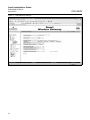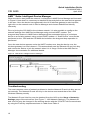
1
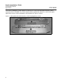
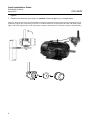
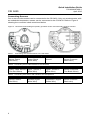
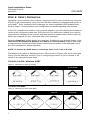
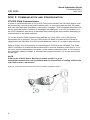
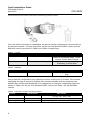
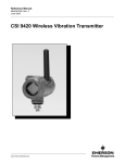
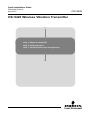
Quick Installation Guide
P/N MHM-97409.4
April 2010
CSI 9420
CSI 9420 Wireless Vibration Transmitter
Start
Step 1: Physical Installation
Step 2: Verify Operation
Step 3: Communication and Configuration
End
www.mhm.assetweb.com
Quick Installation Guide
P/N MHM-97409.4
April 2010
CSI 9420
© 2010 CSI. All rights reserved. All marks property of owner.
Emerson Process Management European Headquarters
Machinery Health Management Interleuvenlaan 50
Emerson Process Management
Asia Pacific Private Limited
835 Innovation Dr.
Knoxville, TN 37932
T (US) (800) 675-4726
F (865) 218-1401
3904 Room Central Plaza
18 Harbour Road Wan-Chai
Hong Kong
T 852-2802-9223
F 852-2802-8227
Reasearch Park Inerleuven
B 3001 Leuven - Belgium
T 32-16-741-403
F 32-16-400-457
IMPORTANT NOTICE
This installation guide provides basic guidelines for the CSI 9420. It does not provide
instructions for detailed configuration, diagnostics, maintenance, service, troubleshooting,
or installations. Refer to the CSI 9420 reference manual (document number P/N 97408)
for more instruction. The manual and this QIG are also available electronically on
www.mhm.assetweb.com.
WARNING
Explosions could result in death or serious injury:
Installation of this transmitter in an explosive environment must be in accordance with the
appropriate local, national, and international standards, codes, and practices. Please
review the Product Certifications section for any restrictions associated with a safe
installation.
• Before connecting a 375 Field Communicator in an explosive atmosphere, ensure the
instruments are installed in accordance with intrinsically safe or non-incendive field
wiring practices.
Electrical shock can result in death or serious injury
• Avoid contact with the leads and terminals. High voltage that may be present on leads
can cause electrical shock.
IMPORTANT NOTICE
The CSI 9420 and all other wireless devices should be installed only after the 1420
Wireless Gateway has been installed and is functioning properly. Wireless devices should
also be powered up in order of proximity from the 1420 Wireless Gateway, beginning with
the closest. This will result in a simpler and faster network installation.
IMPORTANT NOTICE
Shipping considerations for wireless products (Lithium Batteries):
Battery powered units are shipped without the power module installed. Please remove the
power module pack prior to shipping the unit.
Primary lithium batteries are regulated in transportation by the U.S. Department of
Transportation, and are also covered by IATA (International Air Transport Association),
ICAO (International Civil Aviation Organization), and ARD (European Ground
Transportation of Dangerous Goods). It is the responsibility of the shipper to ensure
compliance with these or any other local requirements. Please consult current regulations
and requirements before shipping.
2
Quick Installation Guide
P/N MHM-97409.4
April 2010
CSI 9420
This Quick Installation Guide applies to both the 2.4 GHz and 900 MHz Wireless HART
versions of the CSI 9420. If you are unsure which version the device is, look in the upper
right-hand corner of the nameplate, as illustrated in Figure 1 below.
Figure 1. Nameplates with radio frequency version highlighted by circles
3
Quick Installation Guide
CSI 9420
P/N MHM-97409.4
April 2010
STEP 1: PHYSICAL INSTALLATION
The CSI 9420 and all other wireless devices should be installed only after the 1420 Wireless
Gateway has been installed and is functioning properly.
Powering the CSI 9420
Remove the rear cover of the device to access the power connections. For the battery
powered version, simply plug in the power module. For the externally powered version,
connect a 10...28V DC (24V nominal) power supply to the bottom two screw terminals on
the right (see Figure 3). Pull the wiring through the threaded conduit entry. When selecting
the power supply, note that each CSI 9420 has a peak current draw of 40 mA when awake
and powering sensors.
NOTE:
Wireless devices should be powered up in order of proximity to the 1420 Wireless
Gateway, beginning with the closest device to the 1420. This will result in a simpler
and faster network installation.
GENERAL SENSOR HANDLING INSTRUCTIONS
The CSI 9420 utilizes special low-power sensors available from Emerson. Each sensor
requires a standard 1/4” - 28 mounting location. Refer to the User’s Manual for detailed
sensor mounting instructions. Sensor mounting instructions and practices are also available
in a separate Sensor Installation Guide on the CD packaged with this device and at
www.mhm.assetweb.com.
To maintain mechanical isolation of the sensor, a Remote Mount configuration is required,
as illustrated in Figure 2. In this configuration, the sensor is mounted separately from the
CSI 9420 housing, then connected to the CSI 9420. Although not required for all
installations, it is common to run the cable from the sensor to the housing through conduit.
NOTE:
The word “sensor” applies to both an accelerometer and an accelerometer with
embedded temperature. The word “accelerometer” refers to a sensor that measures
only acceleration.
Remote Mount
1. Install sensor or accelerometers according to standard sensor installation practices. Be
sure to use thread sealant on all connections.
2. Run wiring (and conduit if necessary) from the sensor to the CSI 9420.
3. Pull the wiring through the threaded conduit entry of the CSI 9420. If not using conduit,
an appropriate grommet or cable-gland should be used to provide both strain relief for
the cable and environmental isolation for the CSI 9420.
4. Attach the sensor wiring to the terminals as indicated in tables 1-3.
5. Connect the power pack module or external 24V DC power supply.
6. Close the housing cover and tighten to safety specification. Always ensure a proper seal
by installing the electronics housing covers so that metal touches metal, but do not over
4
Quick Installation Guide
P/N MHM-97409.4
April 2010
CSI 9420
tighten.
7. Position the antenna such that it is vertical, either straight up or straight down.
Figure 2. Remote mounting of the CSI 9420 involves mounting the device away from the equipment to be
measured (upper left), connecting a sensor or accelerometers to the equipment and the CSI 9420 (upper
right), and removing the rear cover and power module of the device to connect the sensor wires (bottom).
5
Quick Installation Guide
CSI 9420
P/N MHM-97409.4
April 2010
Connecting Sensors
One or two accelerometers can be connected to the CSI 9420. Only one accelerometer with
an embedded temperature sensor can be connected to the CSI 9420. Refer to Figure 3
showing the connector labels mentioned below.
Figure 3. CSI 9420 Terminal Diagram (battery powered version and externally powered version)
Table 1. Connecting One Accelerometer to the CSI 9420
Connecting One Accelerometer
Connector labeled 1: Connector labeled 2: Connector labeled 3: Connector labeled 4:
Sensor Power
Sensor Signal
Unused
Sensor Common
(Red Wire)
(White Wire)
(Black Wire)
Table 2. Connecting Two Accelerometers to the CSI 9420
Connecting Two Accelerometers
Connector labeled 1: Connector labeled 2: Connector labeled 3: Connector labeled 4:
Power - Both Sensors Signal - Sensor 1
Signal - Sensor 2
Sensor Commons
(Two Red Wires)
(White Wire)
(White Wire)
(Two Black Wires)
Table 3. Connecting One Sensor with Vibration and Temperature
Connecting One Sensor with Vibration and Temperature
Connector labeled 1: Connector labeled 2: Connector labeled 3: Connector labeled 4:
Sensore Power
Vibration Signal
Temperature Signal Sensor Common
(Red Wire)
(White Wire)
(Green Wire)
(Black wire)
6
Quick Installation Guide
P/N MHM-97409.4
April 2010
CSI 9420
STEP 2: VERIFY OPERATION
Operation can be verified by four methods: Viewing the LCD screen on the device, using the
375/475 Field Communicator, using the 1420 Wireless Gateway’s integrated web server, or
using AMS™ Suite: Intelligent Device Manager (or other compatible HART-enabled host).
Refer to Step 3: Communications and Configuration for details regarding each method.
If the LCD is installed and enabled, during normal operation, the LCD displays the measured
values at the configured update rate. Every time the CSI 9420 device wakes up to make a
measurement it displays these screens and then takes the measurement. Refer to the CSI
9420 User’s Manual for error codes and other LCD messages.
Press the Diagnostic (DIAG) button once and the CSI 9420 will cycle through display of the
TAG, Device ID, Network ID, Network Join Status and Device Status screens, then make
a measurement. Pressing the DIAG button causes this information to be displayed even if
the LCD is disabled for normal operation.
NOTE: To access the DIAG button, remove the front cover of the CSI 9420.
The Network join status as displayed on the LCD is shown in Figures 4 for the 2.4 GHz and
Figure 5 for the 900 MHz versions. Prior to configuring the device to join a network, it will
remain in the Network Search mode.
CSI 9420 2.4 GHz, Wireless HART
Figure 4. Network join status (2.4 GHz)
Searching for Network
Joining Network
Connected
Operational and ready
to send data
CSI 9420 900 MHz
Figure 5. Network join status (900 MHz)
7
Searching for Network
Joining Network
Connected with
1 Parent
Connected with
2 Parents
netwk
netwk
netwk
netwk
a -srch
joing
1parnt
2parnt
Quick Installation Guide
CSI 9420
P/N MHM-97409.4
April 2010
STEP 3: COMMUNICATION AND CONFIGURATION
375/475 Field Communicator
In order to communicate with a 375 or 475 Field Communicator, the CSI 9420 device must
be powered by connecting the power module pack, or connecting external 24V DC power.
Also, the initial boot and acquisition cycle must be complete (This is indicated when the LCD
screen goes blank after a number of messages are displayed). If no LCD is installed, or if
the LCD is disabled, wait about 30 seconds after powering the device before attempting to
communicate on the wired interface.
To use the 375/475 Field Communicator with the rev 3 CSI 9420, a rev 3 DD (Device
Description file) is required. The rev 3 DD for the CSI 9420 is located on the CD that is
shipped with the CSI 9420. 375/475 System Software version 3.2 or later is also required.
Refer to Figure 6 for an illustration of connecting the 375/475 to the CSI 9420. The wired
HART connection is located on the terminal block in the rear chamber of the device. It is a
two-wire, polarity-independent connection. In the battery powered version, it is the bottom
two terminals, labeled “COMM”. In the externally powered version, it is the top two screws
on the right.
NOTE
Refer to the 375/475 Users’ Manual for details on DD’s or go to
www.fieldcommunicator.com/syssoftdds.htm for instructions on adding a DD for the
CSI 9420 or other new devices.
Figure 6. 375 Field Communicator Connections (battery powered version)
8
Quick Installation Guide
P/N MHM-97409.4
April 2010
CSI 9420
375/475 Field Communicator Connections (externally powered version)
Once the wired connection is established, the device can be configured to communicate on
the wireless network. The key sequences for the 2.4 GHz Wireless HART version and the
900 MHz version are shown in Table 4 and Table 5 respectively.
Table 4. 2.4 GHz
Function
Key Sequence
Menu Items
Wireless
2, 2, 2 (Manual Setup)
Wireless
2, 1, 2 (Guided Setup)
Network Identifier, Join Device to
Network, Broadcast Rates, Power
Source, Power Save Publish
Join Device to Network, Configure
Publishing, Publish Rate
Table 5. 900 MHz
Function
Key Sequence
Menu Items
Network
1, 1, 7
Network ID, Set Network ID / Join
Key
Device-specific configuration may optionally be done at this point, if needed. This includes
specifying the type of sensor(s) installed, the process variables that are published, the
publish rate, and the alert thresholds. Key sequences for common configuration tasks are
shown in Table 6 for the 2.4 GHz Wireless HART version and Table 7 for the 900 MHz
version.
Table 6. CSI 9420 2.4 GHz Fast Key Sequence
Function
Key Sequence
Initial Setup
2, 1, 1 (Guided Setup)
Device Setup
Alert Setup
2, 2, 1 (Manual Setup)
2, 3
9
Menu Items
Configure Sensors, Change Variable Mapping,
Change Units, Alert Limits
Units, Sensors, Variable Mappings
Dependent on sensor configuration
Quick Installation Guide
P/N MHM-97409.4
April 2010
CSI 9420
Table 7. CSI 9420 900 MHz Fast Key Sequence
Function
Key Sequence
Device Information
1, 1, 8
Sensor Config
Network
Variable Mapping
Alarm Levels
1, 1, 3
1, 1, 7
1, 1, 2
1, 1, 6
Menu Items
Tag, Date, Descriptor, Message, Distributor, Write Protect,
Model, Dev ID, Final assbly num, Revision #’s
Sensor 1, Sensor 2, Calibration
Network ID, Set Network ID / Join Key
PV is, SV is, TV is, QV is
Overall Velocity Sensor 1, Overall Velocity Sensor 2, PeakVue
Sensor 1, PeakVue Sensor 2, Temperature, Supply Voltage
1420 Wireless Gateway
The wireless network settings can be viewed in the 1420’s web interface. The Network ID
and Join Key needed for theCSI 9420 to join the network can be found on the Setup >
Network > Settings page as illustrated in Figure 7. Select the Yes radio button to display
the Join key.
Once the device has been configured to join the network, navigate to the Explorer page.
This page will show whether the device has joined the network and if it is communicating
properly.
NOTE:
It may take several minutes for the device to join the network.
NOTE:
If the device joins the network and immediately has an alarm present, it is likely due
to sensor configuration. Check the sensor wiring (see figure 3, and tables 1-3) and the
sensor configuration.
10
Quick Installation Guide
P/N MHM-97409.4
April 2010
Figure 7. 1420 Network Settings
11
CSI 9420
Quick Installation Guide
CSI 9420
P/N MHM-97409.4
April 2010
AMS™ Suite: Intelligent Device Manager
When the device has joined the network, it will appear in AMS Device Manager as illustrated
in Figure 8. Note that it is necessary to rebuild the hierarchy before the new device appears
in the tree. Once the device has appeared in the 1420 wireless gateway’s web interface,
right click on the network node in Device Manager and choose Rebuild and Identify
Hierarchy.
Prior to joining the CSI 9420 to the wireless network, it is also possible to configure the
network settings from AMS Device Manager using a wired HART modem. The
drag-and-drop feature in AMS Device Manager allows automated joining of a wireless
device to an existing network using a wired HART modem. A “Scan Device” must first be
performed on the 1420 and the CSI 9420 device before the drag-and-drop operation is
performed.
Once the new device appears under the HART modem tree, drag the device over the
wireless gateway icon and release it. This automatically sets the Network ID and Join Key
and causes the device to join the network when it is in range. Refer to the AMS Device
Manager documentation for additional details.
Figure 8. AMS Suite: Intelligent Device Manager
Troubleshooting
The most common cause of network problems is that the Network ID and Join Key are not
set correctly. The Network ID and Join Key in the device must match that of the 1420
Wireless Gateway exactly.
The Network ID and Join Key may be obtained from the 1420 on the Setup > Network >
Settings page of the web server (see Figure 7: 1420 Network Settings). The Network ID
and Join Key may be changed in the wireless device with the 375/475 Field Communicator
by using the Fast Key sequences shown in Table 8 and Table 9.
12
Quick Installation Guide
P/N MHM-97409.4
April 2010
CSI 9420
Table 8. Join Sequence - CSI 9420 2.4 GHz
Function
Key Sequence
Wireless
Wireless
2, 2, 2, 2 (Manual Setup)
2, 1, 2, 1 (Guided Setup)
Menu Items
Network ID, Join Key
Network ID, Join Key
Table 9. Join Sequence - CSI 9420 900 MHz
Function
Key Sequence
Menu Items
Network
1, 1, 7, 2
Set Network ID / Join Key
PRODUCT CERTIFICATIONS
The CSI 9420 has a number of certifications and approvals including CE, FCC, R&TTE, FM,
CSA, and ATEX. Please refer to the User’s Manual for a complete list of product
certifications. The User’s Manual is included on the CD that ships with the device or it may
be downloaded from the web at www.mhm.assetweb.com. A printed copy of the User’s
Manual (MHM-97408) may be ordered by contacting your local sales representative, or it
can be printed out from the CD.
OPERATING LIMITS
Each of the CSI 9420 signal inputs uses accelerometers to make vibration measurements.
Alternately, an accelerometer with embedded temperature may be used. The operational
ranges for the sensors are shown in Table 10:
Table 10. Sensor ranges
Channel
Accelerometer 1
Accelerometer 2
Temperature 1
DC Bias Range DC Input Range AC Input Range
2 - 3 Vdc
2 - 3 Vdc
N/A
0 - 5 Vdc
0 - 5 Vdc
-40 to +125 C
0 - 5 V (+/-100 gs peak)
0 - 5 V (+/-100 gs peak)
N/A
The accelerometers require a DC bias. The CSI 9420 device provides the necessary bias
and measures it to verify correct sensor operation. The nominal bias voltage is 2.5 volts. If
the bias voltage is outside of the 2 - 3 volt range, the device generates a FAILED alert for the
associated accelerometer. The DC input range represents the operational DC range of the
signal input. The AC input range represents the operational AC range of the signal input.
13
Quick Installation Guide
CSI 9420
14
P/N MHM-97409.4
April 2010