1
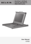
OmniView
1U Rack-Mount Console
™
with 8-Port KVM Switch
Control up to eight servers from one integrated
console and KVM Switch
• Expandable to control up to 256
servers from four consoles
User Manual
ENTERPRISE Quad-Bus Series
F1DC108B
TABLE OF CONTENTS
Introduction . . . . . . . . . . . . . . . . . . . . . . . . . . . . . . . . . . . . . . . . 1
Package Contents . . . . . . . . . . . . . . . . . . . . . . . . . . . . . . . . . . 1
Overview
Product Features . . . . . . . . . . . . . . . . . . . . . . . . . . . . . . . . . . . 2
Equipment Requirements . . . . . . . . . . . . . . . . . . . . . . . . . . . . . . 3
Operating Systems . . . . . . . . . . . . . . . . . . . . . . . . . . . . . . . . . . 3
Specifications . . . . . . . . . . . . . . . . . . . . . . . . . . . . . . . . . . . . . 4
Unit Display Diagrams . . . . . . . . . . . . . . . . . . . . . . . . . . . . . . . .5
Glossary of Terms . . . . . . . . . . . . . . . . . . . . . . . . . . . . . . . . . . . 6
Installation
Pre-Configuration . . . . . . . . . . . . . . . . . . . . . . . . . . . . . . . . . . 7
Standalone KVM Switch—Installation . . . . . . . . . . . . . . . . . . . . . 8
Multiple KVM Switches—Installation (Daisy-Chaining) . . . . . . . . . . 10
DIP Switch Configuration Chart . . . . . . . . . . . . . . . . . . . . .11
Powering Up the Systems . . . . . . . . . . . . . . . . . . . . . . . . . . . . . 14
Using your Switch
Selecting a Computer Using Keyboard Hot Key Commands . . . . . . . . 15
Using the Auto Scan Function . . . . . . . . . . . . . . . . . . . . . . . . . . 15
IntelliView Graphical On-Screen Display (OSD) Menu Control . . . . . . 16
INTRODUCTION
Congratulations on your purchase of this Belkin ENTERPRISE Quad-Bus Series
Rack-Mount Console with 8-Port KVM Switch (the Switch). Our diverse line of KVM
solutions exemplifies the Belkin commitment to delivering high-quality, durable
products at a competitive price.
Designed to give you control over multiple computers and servers from the
Rack-Mount Console, Belkin has designed and developed this Rack-Mount Console
with the server administrator in mind. The result is designed to outperform any
other rack-mount console with KVM switch on the market. The Rack-Mount Console
is engineered to work with the most advanced server room and laboratory
environments, offering:
•
•
•
•
•
•
•
•
•
•
•
•
Dual rail system allowing the LCD panel to be displayed by itself
Video resolution support of up to 1024x768
PS/2 and USB mix-and-match support for input and output devices
Multi-console support
IntelliView Graphical On-Screen Display (OSD)
Computer and group naming
Multilevel security
Computer connection status and diagnosis
Flash-upgradeable firmware
Dual-port connectors (cables sold separately)
Belkin Two-Year Warranty
Free technical support
FAQs . . . . . . . . . . . . . . . . . . . . . . . . . . . . . . . . . . . . . . . . . . . . .24
This User Manual will provide details about your new Switch, from installation and
operation to troubleshooting—in the unlikely event of a problem.
Troubleshooting . . . . . . . . . . . . . . . . . . . . . . . . . . . . . . . . . . . . .25
For quick and easy installation, please refer to the Quick Installation Guide included
in your packaging.
Information . . . . . . . . . . . . . . . . . . . . . . . . . . . . . . . . . . . . . . . .26
Thank you for purchasing the Belkin OmniView ENTEPRISE Quad-Bus Series
Rack-Mount Console with 8-Port KVM Switch. We appreciate your business and have
confidence that you will soon see for yourself why over 1 million Belkin OmniView
products are being used worldwide.
Package Contents
• OmniView ENTERPRISE Quad-Bus Series Rack-Mount Console with
8-Port KVM Switch
• Rack-Mount Brackets with Screws
• User Manual
• Quick Installation Guide
• Registration Card
1
OVERVIEW
OVERVIEW
Product Features
Equipment Requirements
PS/2 and USB Mix-and-Match Keyboard
The KVM Switch enables you to use either USB or PS/2-type keyboard and mouse to
control computers via either their USB or PS/2 interfaces.
Cables
To connect to the Switch, each computer requires a specialized Belkin OmniView
ENTERPRISE Series Dual-Port KVM Cable.
One Dual-Port KVM Cable connects two computers per KVM port.
OmniView ENTERPRISE Series Dual-Port KVM Cables:
F1D9400-XX PS/2 Style; 6, 10, 15, and 25 ft.
F1D9401-XX USB Style; 6 and 12 ft.
F1D9402-XX Daisy-Chain Cable
(-XX denotes length in feet)
Video Resolution
The KVM Switch offers support for video resolutions up to 2048x1536@85Hz through
a 400MHz video bandwidth.
Multi-Console Support
By daisy-chaining additional KVM Switches or Expander units to the Primary console,
the number of users can expand up to as many as four consoles. All four users can
simultaneously control up to 128 computers when used with additional 8-Port KVM
Switches, or as many as 256 when using the 16-Port KVM Switches.
IntelliView Graphical On-Screen Display (OSD) with Mouse Support
The IntelliView Graphical OSD feature simplifies server management by allowing you
to assign individual names to each connected server throughout the system. Groups
of computers can also be created, allowing you to efficiently organize your
enterprise. IntelliView also provides a visual means of switching between computers,
enables the user to check computer connection status, offers multilevel security, and
enables the time interval to be adjusted for the AutoScan function.
Operating Systems
OmniView ENTERPRISE Quad-Bus Series Rack-Mount Consoles with 8-Port KVM
Switches are for use with computers running:
Platforms
•
•
•
•
Windows® 95, 98, 2000, Me, NT®, XP
Red Hat® Linux® 7.0, 7.1, 7.2 and other Linux distributions
Novell® NetWare® 5.x, 6.x
Apple® Macintosh® products (requires USB support or the OmniView Mac
Adapter™ F1D080)
Hot Keys
Hot key functionality allows you to select a desired port using designated key
commands. By using a simple hot key sequence on your keyboard, selecting one
computer from as many as 256 computers is instantaneous.
AutoScan
The AutoScan feature allows you to set your KVM Switch to scan and monitor the
activities of all computers connected to it—one by one. The time interval allotted
for each computer can be defined or adjusted through the IntelliView menu.
AutoUpdate™
Our exclusive AutoUpdate system and flash-upgradeable firmware allow you to obtain
the latest firmware upgrades for your KVM Switch, when necessary. This enables your
KVM Switch to maintain consistent compatibility with the latest devices and
computers. Firmware updates are free for the life of your KVM Switch. Refer to the
enclosed AutoUpdate instruction document, or visit us at belkin.com for complete
update information and support.
2
3
OVERVIEW
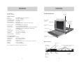
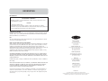
Unit Display Diagrams
Specifications
Part No.: F1DC108B
KVM Specifications
Power:
Daisy-Chain:
Max. Number of PCs:
Keyboard Emulation:
Mouse Emulation:
Monitors Supported:
Keyboard Inputs:
Mouse Inputs:
Computer Ports:
VGA Ports:
Operating Temp:
Storage Temp:
Humidity:
Maximum Altitude:
OVERVIEW
90–264VAC @ 47–63Hz, single phase
Maximum of 16 BANKs
8 per BANK, 128 total
PS/2 & USB
PS/2 & USB
VGA, SVGA, MultiSync®, LCD monitors that accept
analog input
6-pin miniDIN (PS/2), USB type A
6-pin miniDIN (PS/2), USB type A
High-density, 50-pin, SCSI 2-style connector (requires Belkin
ENTERPRISE Series Cable F1D9400-XX or F1D9401-XX)
15-pin HDDB type
32° to 104° F (0~40° C)
-4° to 140° F (-20~60° C)
0-80% RH, non-condensing
10,000 feet
Console Specifications
Max. LCD Resolution: 1024x768
Keyboard Type:
105-key, PS/2-compatible
Mouse Type:
PS/2-compatible touch pad
Enclosure:
Metal enclosure
Dimensions:
19 (W) x 1.75 (H) x 29 (L) in. (482.6 x 44.5 x 736.6mm)
Weight:
29.2 lbs. (13240g)
Warranty:
2-Year Limited Warranty
Note: Specifications are subject to change without notice.
Key-Locking
Mechanism
LCD 15-Inch TFT
Active-Matrix
Color Panel
8-Port ENTERPRISE
Quad-Bus Series
KVM Switch
LCD Front Panel
Controls
105-Key Keyboard
Touch Pad
Power Switch with
Status LED
Back of Console
Video Console
Port
Flash-Upgrade
Port, USB Type B
BANK
Selection
DIP Switch
4 high-density, 50-pin, SCSI 2-style server ports,
each supporting 2 computers
Daisy-Chain
Port, In
PS/2 Console
Ports
Daisy-Chain
Port, Out
IEC Power
Connector
Reset Button
4
5
OVERVIEW
Glossary of Terms
INSTALLATION
Pre-Configuration
The following definitions are used throughout the User Manual:
AutoScan A mode of operation where the KVM Switch sequentially monitors all
attached servers.
BANK The address of a KVM Switch when used in a daisy-chain configuration (BANK
numbers range from 0 to 15); typically set by adjusting the DIP Switch to the
appropriate setting.
The enclosure of the Switch is designed for rack-mount configuration in a standard
19-inch server rack. Rack-mount hardware is included for a sturdy rack installation.
Consider the following when deciding where to place the Switch:
• The location of your computers in relation to where you would like to install
your Switch; and
• The lengths of the cables you use to connect your computers to the Switch.
Console The keyboard, video monitor, and mouse.
Cable Distance Recommendations
Console Ports The connectors on the back of the KVM Switch for connection of
the console.
For PS/2 Computers
Control In terms of switching between ports, “control” means that the console is
capable of sending input to the computer; requires that the console also has “focus”
on the port, and is “viewing” it.
We recommend that PS/2 cable length be limited to 25 feet for best video
performance. Beyond that length, the probability of video degradation increases.
For USB Computers
Daisy-Chaining The process of connecting multiple KVM Switches together in a
sequence with cables. Daisy-chaining allows the KVM Switches to interact with each
other to expand control over servers.
We recommend that USB cable length be limited to 12 feet for best performance.
Beyond 12 feet, the probability of signal failure is likely, and this may cause the
device to fail.
Human Interface Device (HID) A USB device class that includes keyboards and mice.
Installing the Switch into a Server Rack
IntelliView Graphical On-Screen Display (OSD) A graphical user interface that can
be used to control and configure the KVM Switch.
The included mounting brackets feature adjustable positions that allow the Switch to
fit in virtually any four-post, 19-inch server rack.
KVM or KVM Switch A keyboard, video, and mouse switch.
Primary Switch A KVM Switch with a console attached to it and set to BANK
address 0–3.
1.
2.
3.
4.
Secondary Switch Switches not assigned as “Primary Switch” that are connected in a
daisy-chained KVM configuration. These are set to BANK addresses 4–15 and do not
have a console connected directly to them.
Note: If this Switch will be daisy-chained to another KVM Switch, set the BANK address
prior to installing on a rack. Refer to the section in this User Manual labeled “Multiple
KVM Switch—Installation (Daisy-Chaining)”.
Port Receptacle in the KVM Switch for plugging in a computer or input device.
Remove the adjustable brackets from the box.
Select a bracket-hole scheme based upon your server rack’s dept.
Attach the bracket to the side of your Switch with the Phillips screws provided.
Mount the Switch to the rack rail assemblies.
Select Mode The mode of operation a daisy-chained KVM Switch enters when it
receives the first button press from the front panel, in Static mode. Select mode
allows the user to select BANKs, hosts, etc. with the next button press.
Standalone A single KVM Switch configured to function independently of other KVM
Switches.
Static Mode The KVM Switch’s predominant mode of operation, into which it enters
whenever it has not received a button press for at least five seconds.
View In terms of switching between ports, “viewing” means that the console is
receiving video from the computer. Viewing requires that the console also has
“focus” on the port.
6
*** Cautions and Warnings ***
Before attempting to connect anything to the Switch or your computer(s), please
ensure that everything is powered off. Belkin Corporation is not responsible for damage
caused by these actions.
7
INSTALLATION
Standalone KVM Switch—Installation
This section provides complete instructions for the hardware setup of a single
Rack-Mount Console with 8-Port KVM Switch.
Before you begin, determine the type of connection that will be used to connect the
computer to the Switch on each port and select the appropriate KVM cable.
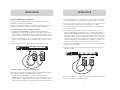
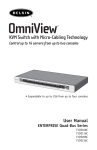
Connecting Computers to the Switch (PS/2 Connection)
1. Using the OmniView ENTERPRISE Series Dual-Port PS/2 Style KVM Cable
(F1D9400-XX), connect the high-density, 50-pin, SCSI 2-style connector to the
next free KVM port, starting with the port for the first two computers (for best
results, screw the connectors into the Switch and the computer, when possible).
2. Connect the VGA and PS/2 connectors of your KVM cable to the server (make sure
that you connect the keyboard and mouse cables to the correct ports on your
server).
3. Repeat steps 1 through 2 for each additional server you wish to connect.
INSTALLATION
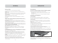
2. Connect the USB connector of your KVM cable to the computer. If your computer
is running Windows Me or later, skip to step 6. Otherwise, continue with step 3.
3. Boot up the computer you wish to connect via USB, as you would normally, with
the keyboard, mouse, and monitor connected directly to the computer.
4. Take the USB cable attached to the Switch and connect it to an available USB
port on your computer.
5. Your computer should detect and identify the Switch as a generic mouse and
keyboard. Manually install the HID device driver by selecting “Next” through the
Windows Hardware Wizard until the HID devices are completely installed (the
Switch will install four devices if not previously installed on your system: an HID
keyboard, an HID mouse, a generic keyboard, and a generic mouse). The driver
installation only needs to be done once for each computer; the Switch will be
detected automatically in the future. When driver installation is complete, power
down the computer and disconnect the keyboard, mouse, and monitor.
6. Connect the male VGA HDDB15 connector located on one end of the KVM cable to
the VGA port on the computer.
7. Repeat steps 1 through 6 for each additional computer you wish to connect to
the Switch via USB.
PS/2 Connection
USB Connection
Connecting Computers to the Switch (USB Connection)
Note: Early versions of Windows operating systems do not automatically install HID
devices. Manual installation of the HID driver may be required.
1. Using the OmniView ENTERPRISE Series Dual-Port USB Style KVM Cable
(F1D9401-XX), connect the high-density, 50-pin, SCSI 2-style connector to the
next free KVM port, starting with the port for the first two computers (for best
results screw the connectors into the Switch and the computer, when possible).
8
Note: For USB installation, we recommend you attach the KVM cable directly to a free
USB port on your computer, not through a USB hub.
9
INSTALLATION
Multiple KVM Switches—Installation (Daisy-Chaining)
You can daisy-chain up to 16 ENTERPRISE Quad-Bus Series KVM Switches together,
giving a server administrator control over a maximum of 256 servers. In addition,
when multiple units are daisy-chained together, three additional consoles can be
added, creating a configuration of up to four consoles.
When daisy-chained together, each unit is referred to as a “BANK” and is assigned
an address. The Rack-Mount Console with KVM Switch is referred to as a “Primary”
Switch. BANKs 00 through 03 can be configured as Primary Switches, allowing up to
four consoles. BANKs 04 through 15 can only be configured as Secondary Switches
(without console support). If BANKs 00 through 03 do not have a console attached,
they function as the Secondary. However, the connections are hot swappable, so if a
console is added to one of the first four BANKs, it will immediately become a
Primary Switch.
Note: A Daisy-Chain Cable (F1D9402-XX) is required to daisy-chain each Switch and is
available through your Belkin reseller or online at belkin.com.
All ENTERPRISE Quad-Bus Series KVM Switches feature a “BANK DIP” Switch. The
BANK DIP Switch is used for proper identification of the KVM Switch, either in a
standalone or multiunit configuration.
• For a single-unit configuration, set the BANK DIP Switch on the KVM Switch to
the “Standalone” (BANK address 00) setting. This is the factory default setting.
• For multiunit configuration, the BANK DIP Switch on the Primary Switches
must be set to BANK address 00 to 03. Secondary Switches must be set to a
unique BANK address (from 00 through 15). Refer to the chart on the next page
for DIP Switch settings.
INSTALLATION
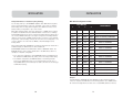
DIP Switch Configuration Chart
1
DIP SWITCH #
2
3
BANK ADDRESS
4
DOWN
DOWN
DOWN
DOWN
BANK 00 (Default)
UP
DOWN
DOWN
DOWN
BANK 01 PRIMARY/SECONDARY
DOWN
UP
DOWN
DOWN
BANK 02 PRIMARY/SECONDARY
UP
UP
DOWN
DOWN
BANK 03 PRIMARY/SECONDARY
DOWN
DOWN
UP
DOWN
BANK 04 SECONDARY
UP
DOWN
UP
DOWN
BANK 05 SECONDARY
DOWN
UP
UP
DOWN
BANK 06 SECONDARY
UP
UP
UP
DOWN
BANK 07 SECONDARY
DOWN
DOWN
DOWN
UP
BANK 08 SECONDARY
UP
DOWN
DOWN
UP
BANK 09 SECONDARY
DOWN
UP
DOWN
UP
BANK 10 SECONDARY
UP
UP
DOWN
UP
BANK 11 SECONDARY
DOWN
DOWN
UP
UP
BANK 12 SECONDARY
UP
DOWN
UP
UP
BANK 13 SECONDARY
DOWN
UP
UP
UP
BANK 14 SECONDARY
UP
UP
UP
UP
BANK 15 SECONDARY
Example:
Four KVM Switches (F1DC108B and three F1DE108C) are daisy-chained together to
control 32 computers. The DIP Switch on the Primary Switch is set to “BANK address
00” and the Secondary Switches are each set to a unique BANK (between 01 and 15).
10
11
INSTALLATION
Installation
Before you begin:
1. Make sure that all computers and Switches are powered off and that each Switch
has been assigned a unique BANK address.
2. Place all Primary and Secondary Switches in the desired location.
3. Connect the servers to the Switch as previously described for a standalone
configuration.
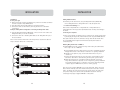
Example of Daisy-Chain Configuration: Connecting the Daisy-Chain Cable
4. Using the Daisy-Chain Cable (F1D9402-XX), connect one end of the cable to the
“Daisy-Chain OUT” port on the first Switch.
5. Connect the other end of the Daisy-Chain Cable to the “Daisy-Chain IN” port of
the second Switch.
Note: It does not matter which unit is the Primary Switch, only that the cables are
always connected “OUT to IN” or “IN to OUT”.
INSTALLATION
Adding Additional Units
6. Continuing in the same manner, using the Daisy-Chain Cable (F1D9402-XX),
connect “Daisy-Chain IN” to “Daisy-Chain OUT” on all subsequent units.
*** Cautions and Warnings ***
Never connect “Daisy-Chain IN” to “Daisy-Chain IN” or “Daisy-Chain OUT” to
“Daisy-Chain OUT”. This may produce unpredictable results and may cause damage to
the Switch.
Connecting the Computers
7. Power on the Switches in whatever order is convenient. You should see them light
up and display the digits “XX”, where XX denotes their respective BANK addresses.
Note: If the Switches still do not enumerate correctly, check that all Switches have
the correct BANK address assigned to them and that all daisy-chain cables are
connected properly.
Enabling Daisy-Chain Mode on BANK 00
8. Primary BANK 00 must be configured to daisy-chain mode by the administrator.
This is only to be set on BANK 00.
a) Open IntelliView and enter “Setup”. Refer to the section “IntelliView On-Screen
Display Menu Control” in this manual for instruction on operating IntelliView.
b) Navigate to the “Options” page, and check the “Allow this box to join a
cluster” box.
c) A dialog box will appear that says “You must power cycle the KVM for this to
take effect.” Click “OK” to clear the dialog box and power cycle the Switch.
d) When the Switch reboots, it will interact with the remainder of the other
daisy-chained Switches as expected. You can verify this by opening IntelliView
and scrolling through the list of computers. If any of the other daisy-chained
computers appear in BANK 00’s list, then it is working properly.
Note: If you don’t configure BANK 00 for use on the daisy-chain, then it will not be
able to interact with any of the other Switches and they will not be able to interact
with it. In addition, the unit’s front panel will not act the same as the other units’
front panels. Finally, there could be some unpredictable interactions caused by
connecting an improperly configured BANK 00 to a daisy-chain.
12
13
INSTALLATION
USING YOUR SWITCH
USING YOUR SWITCH
Powering Up the Systems
Selecting a Computer Using Keyboard Hot Key Commands
Once all cables have been connected, power up the connected computers. All
computers can be powered on simultaneously. The Switch emulates both a mouse
and keyboard on each port and allows your computer to boot normally.
Command the Switch to switch ports through simple keyboard key sequences. To
initiate a keyboard command to the Switch, press the “Scroll Lock” key twice within
one second (you will hear a beep), then input the key sequence for the specific
command. Below is a list of the different keyboard commands:
The computer connected to port “01” of the Primary Switch will be displayed on the
monitor. Check to see that the Switch is working normally by use of mouse, keyboard,
hot keys, and/or IntelliView. Proceed to do this with all occupied ports to verify that
all computers are connected and responding correctly. If you encounter an error,
check your cable connections for that computer and reboot, if necessary. If the
problem persists, please refer to the “Troubleshooting” section of this User Manual.
Now that you have connected your computers to your Switch, it is
ready for use. You can select connected computers by key commands or the
On-Screen Display. It takes approximately 1–2 seconds for the video signal to
refresh (depending on monitor and graphics card used) after switching computers.
Note: For hot keys (e.g. up and down arrows) and AutoScan, the order of progression,
when switching from one computer to the next, is dictated by the order of the
computers in the list box (on the main page of IntelliView).
Note: You will have approximately two seconds after the beep to complete each hot
key sequence.
For hot keys (e.g. up and down arrows) and AutoScan, the order of progression from
one computer to the next is dictated by the order of the computers in the list box
(in the main view of IntelliView).
Note: Alternatively, the control keys can be used to enter commands (usage is identical
to the Scroll Lock key); this provides compatibility for keyboards that don’t have Scroll
Lock keys.
Using the AutoScan Function
In AutoScan mode, the Switch remains on one port for a configured interval
(1–99 seconds) before switching to the next computer. The time interval is
configured in IntelliView.
To enter AutoScan mode, press the AutoScan button in IntelliView:
• AutoScan mode will continue indefinitely until terminated by pressing any valid
hot key sequence.
• When the Switch is in AutoScan mode, it is also in View-Only mode. This means
that input from the console will not be transmitted to the server in focus. Cancel
AutoScan to regain control of the computer.
• The AutoScan time varies by computer, and is configured in IntelliView.
• AutoScan will skip any servers that the user does not have permission to view.
Using the MultiView Feature
This Switch is capable of allowing multiple users to view the same server
simultaneously; however, only the first console to focus on that server will have
control (be capable of input). When a second console focuses on the same server,
the View-Only console’s banner will display “View-Only”. If the banner is enabled on
the viewing console, then the “View-Only” banner will be displayed as long as that
console is focused on a computer it can’t control. If the banner is disabled on the
viewing console, then the “View-Only” banner will be displayed for five seconds.
If the controlling console switches focus to another computer, then control will be
granted to another console.
14
15
USING YOUR SWITCH
IntelliView Graphical On-Screen Display (OSD) Menu Control
IntelliView is intended to have a look and feel similar to Windows-based operating
systems popular on personal computers. To bring up IntelliView, press on “Scroll Lock
+ Scroll Lock + Space Bar”.
General IntelliView Features
The main page is the initial screen that will appear after opening IntelliView. The
graphical OSD screen layout is similar to many Windows-based systems that exist.
The user will see a window with a title bar containing some controls and a main area
where the user accesses the features of the Switch. The top-right side of the OSD
title bar identifies the console that is being used and the user that is currently
logged in. Selecting the “?” button will display the help screen. The help screen will
show a description of the current page and will describe all available controls.
Selecting the “X” button will close the page the user is viewing. The main page also
has an “Exit” button that closes IntelliView. The exit button is the default key, so
pressing “Enter” will also exit IntelliView, unless another button has focus.
Note: All changes to IntelliView are written and saved to memory as soon as the focus
changes; there is no method of canceling or undoing actions once they have been
entered. However, in the case of edit boxes (e.g. the “Computer Name” edit box), ESC
will exit the control and revert the contents to their original form.
Input and Navigation Features
• Clicking on the “Group”, “Computer Name”, or “ID” column headers will sort the
list box entries in ascending order, by the column header selected.
• Single-clicking on a computer line will select that computer line.
• Double-clicking on a computer line will select that computer line and switch the
console’s focus to the selected port. If the user is restricted from accessing the
computer selected, an error message will be displayed. When the error dialog box
is cleared, the console’s focus will remain on the previously selected port.
• Pressing the up or down arrow keys, while IntelliView is up, will move the
computer cursor (the row highlighted blue) up or down. If the cursor moves
outside of the visible area, the list will scroll by one line. The scroll wheel on the
mouse can also be used to perform this function.
• The up/down double arrows, to the right of the computer list, scroll the list up
and down one page at a time. The “Page Up” and “Page Down” keys on the
keyboard will also perform this function.
• Pressing the space bar will activate IntelliView’s control in focus (same as
clicking on the control). If the list box is in focus, then pressing the space bar
will give the console control of the highlighted computer.
16
USING YOUR SWITCH
• Pressing “Enter” will activate the control in focus if the control is on a button or
inside an edit box. However, if the focus is on another type of control (e.g. the
list box), the Enter key will activate the default control (“Close” or “Exit”,
depending on the current IntelliView screen).
• If the administrator presses “Ctrl+TAB” while viewing one of the setup pages,
IntelliView will switch to the next page.
• Accelerator keys that have been enabled will activate their respective controls
(i.e. pressing “Alt+{A-Key}”, where the A key corresponds with a character that is
underlined in a control label).
• When IntelliView is active, keyboard and mouse input is routed to IntelliView;
nothing is sent to the computer that the console controls.
• Selecting the “Close” button (or pressing “Alt+C”) on any of the setup pages will
return the user to the main page.
• The “Tab” key can be used to cycle through the controls on the current
IntelliView page.
• IntelliView’s window can be repositioned by clicking on the title bar and
dragging the window with the mouse.
• To reposition the banner, press “Ctrl+Alt” while IntelliView is up. The cursor will
jump from IntelliView’s window to the banner; clicking and dragging the mouse
will allow the user to reposition the banner.
• The size and position of the IntelliView window and banner vary with the
resolution and refresh rate of the video card. To improve the user’s ability to
position the IntelliView window where they desire, the Switch preserves the
position of the IntelliView window for several different resolution/refresh rates.
This feature will help the user to position the IntelliView window and the banner
where they want them, but the user may have to set the positions of the
IntelliView window and banner windows multiple times during KVM setup before
they remain in a consistent location.
The Main Page
Group Column
The “Group” column displays the name of the group to which the server has been
assigned. The group name is assigned by the Switch’s administrator (see the
“Administrator Setup Page” section for information on changing the group name).
The “Computer Name” list can be sorted on this field by clicking on the column header.
Computer Name Column
The “Computer Name” column displays the name of each connected computer/server.
The computer name can be set by the Switch’s administrator (see the “Server Page”
section for information on changing the computer name). The computer list can be
sorted on this field by clicking on the column header.
17
USING YOUR SWITCH
ID Column
This column displays the BANK and port number of the Switch where the computer
is connected. The computer list can be sorted on this field by clicking on the
column header.
Keyboard Column
The “Keyboard” column shows the status of the current keyboard connection, and
is updated in real time. If the connection to the computer is via a PS/2 cable, a
small keyboard icon is displayed. If the keyboard connection to the computer is via
USB, the USB trident symbol is displayed. If no keyboard is detected, the cell will
be empty.
Mouse Column
The “Mouse” column shows the status of the current mouse connection, and is
updated in real time. If the connection to the computer is via a PS/2 cable, a small
mouse icon is displayed. If the mouse connection to the computer is via USB, the
USB trident symbol is displayed. If no mouse is detected, the cell will be empty.
Security Column
This column displays the security settings for the current user. If this user is blocked
from accessing a computer, a closed-padlock symbol is displayed. If the user is
allowed to access the computer, the cell is empty.
Note: The KVM administrator can prevent computers from appearing in the Main View if
the user doesn’t have rights to access them. (For additional information, see the
“Options Page” section.)
Console Column
The Console currently viewing the computer is indicated in this column by its
corresponding letter (A-D). If multiple consoles are focused on the same computer,
the letter of one that has control of the computer will appear in the console cell.
Scan Button
Click the “Scan” button or press “Alt+A” on the keyboard to activate the AutoScan
feature. This will not close IntelliView.
Setup Button
Click the “Setup” button or press “Alt+S” on the keyboard to access IntelliView’s
setup pages. If the user is not logged in as the administrator, the setup button will
not be selectable (will appear gray). The setup pages are only accessible to one
console at a time. If two administrators attempt to access the setup pages
simultaneously, the second administrator will be presented with an error message.
18
USING YOUR SWITCH
Login Button
Click on the “Login” button or press “Alt+L” on the keyboard to display the login
dialog box, which lets the user switch to a different “account” (see the “Login
Dialog” section).
Logout Button
Click on the “Logout” button or press “Alt+T” on the keyboard to return to “Guest”
level access. If the administrator has removed guest access, video will go black when
the user logs out of the computer, and that port will lose control of the computer.
The hot keys and the front panel are also disabled; the only command sequence the
Switch will accept is “Scroll Lock + Scroll Lock + Space” (open IntelliView), which
will present the user with the login dialog box.
Exit Button
The “Exit” button (or “Alt+X”) closes IntelliView, allowing the user an unrestricted
view and control over the computer in focus.
Administrator Setup Page
The setup page is only available to the admin user and is used to set the group
name, computer name, and computer scan times. The scan time is dependent on the
port being scanned, and is global (i.e. it’s independent of the console or user). While
scan times are independent of the user, AutoScan will skip computers that the user
does not have permission to view.
Group Column
The “Group” column displays the name of the group to which the computer has been
assigned. The group name is arbitrary text, purely for organizational purposes. The
group name can be up to eight alphanumeric characters and is assigned by the KVM
administrator. The default group name of a computer is “Group X”, where X is the
BANK number of a KVM Switch as determined by the BANK address DIP Switch. To
change the group name, click in the desired cell.
Computer Name Column
The “Computer Name” column displays the name of each connected computer. The
computer name can be up to 15 alphanumeric characters and is assigned by the KVM
administrator. The computer list can be sorted on this field by clicking on the column
header. By default, all computer names will be named BANK XX-Port YY, where XX is a
two-digit BANK address number from 00 to 15 and YY is a two-digit computer number
from 01 to 16. To input the computer name, click in the desired cell.
19
USING YOUR SWITCH
USING YOUR SWITCH
ID Column
This column displays the BANK and port number of the Switch where the computer is
connected. The computer list can be sorted on this field by left-clicking the mouse
on the column header.
User Columns (1, 2, 3, G)
These columns allow administrators to set the access rights to each computer for
each of the “User” groups (1, 2, 3, and Guest). To restrict a user from a particular
computer, click in the corresponding cell in the list box. The padlock indicates that
the user (column) will be restricted from accessing that computer (row). Empty cells
indicate that the user has full access to that computer.
Scan Column
The “Scan” column displays the current setting for how long the console views each
computer during AutoScan. To change the viewing duration for a computer, click in
the desired cell.
Scan Time and Change All Button
The user can reset the scan time for all computers by entering a value from 1–99
in the edit box and clicking on the “Change All” button. The user will be asked to
confirm the action before the new time is applied.
Console Column
The console currently viewing the computer is indicated in this column.
Security Page
The “Security” page allows the administrator to restrict computer access for the
Switch’s users. There are three levels of user access to the Switch: administrator,
user, and guest. The administrator is the only user that can access the setup pages
to configure the Switch. The administrator can restrict users and guests from
accessing specific computers. All users can switch computers and toggle the
AutoScan function in the main page. In addition, the guest is the default user
(you never have to login as “Guest”), so all users log off to “Guest” when the
account is enabled. If the administrator has removed guest access, video will go
black when the user logs out the computer, and that port will lose control of the
computer. The hot keys and the front panel are also disabled; the only command
sequence the Switch will accept is “Scroll Lock + Scroll Lock + Space” (open
IntelliView), which will present the user with the login dialog box. The “User”
accounts defined in the Switch can be used by individuals or groups of individuals;
the names of the users are fixed.
Group Column
The “Group” column displays the name of the group to which the computer has been
assigned. The computer list can be sorted on this field by clicking the mouse on the
column header.
Computer Name Column
The “Computer Name” column displays the name of each connected computer. The
computer list can be sorted on this field by clicking on the column header.
20
Console Column
The console currently viewing the computer is indicated in this column.
Passwords Page
The “Passwords” page allows the administrator to change user passwords, enable or
disable user accounts, and set the Auto Logout time.
Password Entry Fields
There is a “Change Password” button associated with each user; clicking the button
displays the “Password Entry” dialog box. The administrator is required to type the
password and then confirm it; the new password will not be accepted until the
entries match (passwords are up to eight characters long and case-sensitive).
Canceling the “Change Password” dialog box will return to the passwords page
without changing the existing password. In a daisy-chain configuration, clicking
“OK” automatically synchronizes this password with the other consoles.
Enable Check Boxes
The check boxes next to the user names allow the administrator to disable user
accounts with a single mouse click. This removes the need to alter the security
settings of each host individually when it is necessary to remove a user’s access.
Auto Logout Enable and Time
The Auto Logout feature logs off the user after a specified period (1–99 minutes) of
console inactivity. Generally, this will return the Switch to “Guest” level access, but
if guest access has been disabled, all access rights will be revoked until a valid user
logs on to the console. The edit box sets the length of inactivity required before the
logout occurs.
Broadcast Passwords
This check box forces all other consoles to overwrite all of their user passwords
with the passwords contained in the current console. This makes it simple for the
administrator to synchronize the passwords of all consoles (e.g. when adding a
new console to an existing configuration).
21
USING YOUR SWITCH
Options Page
The controls on this page affect several of the Switch’s miscellaneous features.
Display Banner
This check box enables a banner to be displayed for system events: hot key switching,
powering on the Switch, etc. The banner is either always displayed, or displayed for
a configured time (1–99 seconds). If the timed selection is enabled, the time input
determines how long the banner will remain on-screen after the system event occurs.
Display Inactive Ports
Enabling this feature will cause ports that do not have an active computer attached
to appear in the computer list box (on the main page of IntelliView). By default,
inactive ports are displayed.
Display Restricted Ports
Enabling this feature will cause ports that the current user is restricted from accessing
to appear in the computer list box (on the main page of IntelliView). By default,
restricted ports are displayed.
Daisy-Chain this KVM
Checking this box allows Switches set to BANK 00 to communicate with other BANKs
in a daisy-chain configuration. This affects front-panel operations and a few other
miscellaneous operational parameters. Whenever the state of this check box is
changed, a message will be displayed requiring the user to reboot the Switch. The
Switch will continue to operate correctly without rebooting, but the setting of this
check box will not take effect until the Switch is rebooted. By default, Switches set
to BANK 00 are configured as standalone (the check box is cleared). This is only
required for BANK 00.
Display Version Numbers
This screen displays product information, including the model number and the
firmware revisions.
USING YOUR SWITCH
Error Messages and Dialogs
From time to time, it will be necessary to display messages to the user indicating
errors or requesting simple answers to questions. These pop-up screens will have
the familiar format of title bar and window body, which will contain the text of the
message. There will also be appropriate response controls such as “OK” and “Cancel”
buttons, based on the nature of the message.
Login Dialog
The “Login Dialog” box is a simple window with radio buttons to select the user, and
an edit box for users to enter their password. If users are already logged in, pressing
“Cancel” will return them to their current login (or “Guest” if the account is
enabled). If the user is not logged in, and “Guest” is disabled, pressing “Cancel” will
close IntelliView.
Help Screens
Extensive help is available within IntelliView; simply press the F1 key, or click on the
“?” button on the right side of the title bar.
Banner
The banner is a small window that is displayed to inform the user of the console’s
focus. The banner looks like a line of text surrounded by a gray frame with the
typical 3D look. The banner will display the following:
• Group Name
• Host Name
• BANK and port in focus
Splash Screen
When the Switch powers on, it will display a splash screen with the product name
and copyright information. This screen will remain for several seconds before it
disappears. Calling up IntelliView will dispel this screen immediately.
Restore Factory Defaults
Clicking on this button will restore all user-configurable settings to their default values.
The user is presented with a confirmation screen before this action is applied.
22
23
FAQs
What operating systems does the Switch support?
The Switch will support any operating system that runs on a PS/2 and USB platform.
Operating systems include, but are not limited to, DOS, Windows 95, 98, 2000, Me,
NT, XP, Linux, and Mac OS.
What does flash-upgradeable mean?
With flash-upgrade capability, you can update your Switch at any time through
a simple parallel connection. Internet-upgrade capability ensures that your
Switch is always the most current version on the market with the latest features
and enhancements.
Does the Switch support Microsoft IntelliMouse?
The Switch supports mice from Microsoft, Logitech®, Kensington®, and Belkin. Please
contact Belkin Technical Support for compatibility issues you may encounter.
How does the Switch allow the user to switch between ports?
The Switch supports two methods of port selection. The user can select computers
using specially designated keyboard hot keys or IntelliView.
How far can the computer be from the Switch?
When using PS/2 connections, the Switch can be up to 25 feet away from your
computer. If your computer needs to be more than 25 feet (7.5 meters) from the
Switch, you can use the Belkin CAT5 Extender to place your monitor and PS/2
keyboard and PS/2 mouse up to 500 feet away using a standard CAT5 UTP cable.
When using a USB connection between your Switch and computer, we recommend
that your computer be no more than 12 feet (4 meters) from the Switch.
What is the maximum video resolution that the LCD panel supports?
The LCD panel supports a resolution of 1024x768.
Do I have to install any software to use the Switch?
No, the Switch does not require any drivers or software to be installed in your
computers. Simply connect all your computers to the PC ports on the Switch and it
is ready for use.
Can I use the Switch on my Sun™ computer that supports USB?
Yes, the Switch works with any USB-capable computer.
Can I daisy-chain my Switch with a Belkin PRO2 or MATRIX2 Series KVM Switch?
No, the Switch cannot be daisy-chained to the PRO2 and MATRIX2 Series KVM
Switches. You may only daisy-chain the Switch with other ENTERPRISE Quad-Bus
Series KVM units (F1DE108C, F1DE116C, F1DE208C, F1DE216C, F1DE008C, and F1DE016C)
24
TROUBLESHOOTING
General
My Switch doesn’t appear to be on.
• Make sure that the power switch located at the front of the keyboard drawer is “on”
and that the power cable is properly plugged in.
Video
I am getting ghosting, shadowing, or fuzzy images on my monitor.
• Check that all video cables are inserted properly.
• Check that your computer isn’t set to a resolution above 1024x768.
• Check that the graphics card you are using supports the resolution and refresh-rate
setting on your computer.
• Connect a monitor directly into the computer you are having trouble with to see if
the problem still appears.
I am getting a black screen on my monitor.
• Check that all video cables are inserted properly.
• Connect a monitor directly into the computer you are having trouble with to see if
the problem still appears.
Keyboard
The computer does not detect a keyboard and I get a keyboard error reported at boot up.
• Check that the cable between the Switch and the computer is completely
connected. Tighten any loose connections.
• Try connecting the computer to a different port.
USB
I am connecting my computer to the Switch via USB and my keyboard and mouse do
not work.
• Prior to connecting the Switch, make sure that the HID USB driver is installed on
each computer. (To install the HID USB driver, connect a USB mouse and USB
keyboard to the computer. A Windows operating system should automatically
install the drivers.)
25
INFORMATION
FCC Statement
DECLARATION OF CONFORMITY WITH FCC RULES FOR
ELECTROMAGNETIC COMPATIBILITY
We, Belkin Corporation, of 501 West Walnut Street, Compton, CA 90220, declare under our sole
responsibility that the products:
F1DC108B
to which this declaration relates:
Comply with Part 15 of the FCC Rules. Operation is subject to the following two conditions:
(1) this device may not cause harmful interference, and (2) this device must accept any interference
received, including interference that may cause undesired operation.
CE Declaration of Conformity
We, Belkin Corporation, declare under our sole responsibility that the products F1DC108B to which this
declaration relates, are in conformity with Emissions Standard EN55022 and with Immunity Standard
EN55024, LVP EN61000-3-2, and EN61000-3-3.
ICES
This Class B digital apparatus complies with Canadian ICES-003. Cet appareil numérique de la classe B
est conforme á la norme NMB-003 du Canada.
belkin.com
Belkin Corporation
Belkin Corporation Limited Five-Year Product Warranty
Belkin Corporation warrants this product against defects in materials and workmanship for its warranty
period. If a defect is discovered, Belkin will, at its option, repair or replace the product at no charge
provided it is returned during the warranty period, with transportation charges prepaid, to the
authorized Belkin dealer from whom you purchased the product. Proof of purchase may be required. This
warranty does not apply if the product has been damaged by accident, abuse, misuse, or
misapplication; if the product has been modified without the written permission of Belkin; or if any
Belkin serial number has been removed or defaced.
501 West Walnut Street
Compton • CA • 90220 • USA
Tel: 310.898.1100
Fax: 310.898.1111
Belkin Components, Ltd.
Express Business Park • Shipton Way • Rushden
NN10 6GL • United Kingdom
Tel: +44 (0) 1933 35 2000
Fax: +44 (0) 1933 31 2000
Belkin Components B.V.
THE WARRANTY AND REMEDIES SET FORTH ABOVE ARE EXCLUSIVE IN LIEU OF ALL OTHERS, WHETHER
ORAL OR WRITTEN, EXPRESSED OR IMPLIED. BELKIN SPECIFICALLY DISCLAIMS ANY AND ALL IMPLIED
WARRANTIES, INCLUDING, WITHOUT LIMITATION, WARRANTIES OF MERCHANTABILITY AND FITNESS FOR
A PARTICULAR PURPOSE.
Starparc Building • Boeing Avenue 333
1119 PH Schiphol-Rijk • The Netherlands
Tel: +31 (0) 20 654 7300
Fax: +31 (0) 20 654 7349
Belkin, Ltd.
No Belkin dealer, agent, or employee is authorized to make any modification, extension, or addition to
this warranty.
BELKIN IS NOT RESPONSIBLE FOR SPECIAL, INCIDENTAL, OR CONSEQUENTIAL DAMAGES RESULTING FROM
ANY BREACH OF WARRANTY, OR UNDER ANY OTHER LEGAL THEORY, INCLUDING BUT NOT LIMITED TO,
LOST PROFITS, DOWNTIME, GOODWILL, DAMAGE TO OR REPROGRAMMING OR REPRODUCING ANY
PROGRAM OR DATA STORED IN OR USED WITH BELKIN PRODUCTS.
Some states do not allow the exclusion or limitation of incidental or consequential damages or
exclusions of implied warranties, so the above limitations of exclusions may not apply to you.
This warranty gives you specific legal rights, and you may also have other rights that vary from
state to state.
26
7 Bowen Crescent • West Gosford
NSW 2250 • Australia
Tel: +61 (0) 2 4372 8600
Fax: +61 (0) 2 4372 8603
Belkin Tech Support
US: 310.898.1100 ext. 2263
800.223.5546 ext. 2263
Europe: 00 800 223 55 460
Australia: 1800 666 040
P74379-A
© 2003 Belkin Corporation. All rights reserved. All trade names are
registered trademarks of respective manufacturers listed. Apple, Macintosh, and Mac OS are
trademarks of Apple Computer, Inc., registered in the U.S. and other countries.