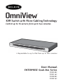
1
OmniView
™
KVM Switch with Micro-Cabling Technology
Control up to 16 servers from up to two consoles
• Expandable to up to 256 from up to four consoles
User Manual
ENTERPRISE Quad-Bus Series
F1DE108C
F1DE116C
F1DE208C
F1DE216C
TABLE OF CONTENTS
Introduction
Overview
Feature Overview . . . . .
Equipment Requirements
Operating Systems . . . .
Specifications . . . . . . .
Unit Display Diagrams .
.
.
.
.
.
.
.
.
.
.
.
.
.
.
.
.
.
.
.
.
.
.
.
.
.
.
.
.
.
.
.
.
.
.
.
.
.
.
.
.
.
.
.
.
.
.
.
.
.
.
.
.
.
.
.
.
.
.
.
.
.
.
.
.
.
.
.
.
.
.
.
.
.
.
.
.
.
.
.
.
.
.
.
.
.
.
.
.
.
.
.
.
.
.
.
.
.
.
.
.
.
.
.
.
.
.
.
.
.
.
.
.
.
.
.
.
.
.
.
.
.
.
.
.
.
.
.
.
.
.
.
.
.
.
.
.
.
.
.
.
.
.
.
.
.
.
.
.
.
.
2
4
4
5
6
Installation
Pre-Configuration . . . . . . . . . . . . . . . . . . . . . . . . . . . . . . . . . . 8
Standalone Switch Installation . . . . . . . . . . . . . . . . . . . . . . . . . .9
Connecting Multiple Switches (Daisy-Chaining) . . . . . . . . . . . . . . .13
DIP Switch Configuration Chart . . . . . . . . . . . . . . . . . . . . . . . . .14
Powering Up the Systems . . . . . . . . . . . . . . . . . . . . . . . . . . . . . 17
Using Your Switch
Selecting a Computer Using Direct-Access Port Selectors . . . . . . . . 18
Selecting a Computer Using Keyboard Hot Key Commands . . . . . . . . 20
AutoScan Mode . . . . . . . . . . . . . . . . . . . . . . . . . . . . . . . . . . . 21
IntelliView Graphical On-Screen Display Menu Control . . . . . . . . . . .22
The AutoUpdate™ Firmware Update Utility . . . . . . . . . . . . . . . . . .34
Troubleshooting . . . . . . . . . . . . . . . . . . . . . . . . . . . . . . . . . . . . .42
Glossary . . . . . . . . . . . . . . . . . . . . . . . . . . . . . . . . . . . . . . . . . . .44
Information . . . . . . . . . . . . . . . . . . . . . . . . . . . . . . . . . . . . . . . .46
INTRODUCTION
Congratulations on your purchase of this Belkin OmniView ENTERPRISE Quad-Bus
Series KVM Switch with Micro-Cabling Technology (the Switch). Our diverse line of
KVM solutions exemplifies the Belkin commitment to delivering high-quality, durable
products at a competitive price. Designed to give you control over multiple
computers and servers from up to four consoles, the Switch comes in a variety of
capacities suitable for all configurations, large or small.
Belkin has designed and developed this Switch with the server administrator in
mind. The result is the OmniView ENTERPRISE Quad-Bus Series KVM Switch, which
surpasses any other switch on the market. The Switch is engineered to work with the
most advanced server room and laboratory environments, offering:
•
•
•
•
•
•
•
•
•
•
•
•
•
Dual-console* support, expandable to up to 4 consoles
IntelliView Advanced Graphical On-Screen Display
PS/2 and USB mix-and-match keyboard & mouse support
Multilevel security feature
USB flash-upgradeable
Dedicated daisy-chain ports
High video-resolution support (400MHz: up to 2048x1536@85Hz)
Computer naming & group naming
Server connection diagnostics
Intuitive port indicators
Direct-access port selectors
Belkin 5-Year Warranty
Dual-port, micro-construct KVM cables (sold separately)
*Available on 2x8 and 2x16 models only
This manual will provide details about your new Switch, from installation and
operation to troubleshooting–in the unlikely event of a problem. From time to time,
Belkin may release updates to this product; updated user information will be
available from our website belkin.com.
For quick and easy installation, please refer to the included Quick Installation Guide.
Thank you for purchasing the Belkin OmniView ENTERPRISE Quad-Bus Series KVM
Switch. We appreciate your business and have confidence that you will soon see for
yourself why over 1 million Belkin OmniView products are being used worldwide.
Package Contents:
• One OmniView ENTERPRISE Quad-Bus Series KVM Switch with Micro-Cabling
Technology
• Two Rack-Mount Brackets with Screws
• User Manual
• Quick Installation Guide
• IEC Power Supply Cable
• Registration Card
• One Set of Rubber Feet
1
OVERVIEW
Feature Overview
Quad-Bus Technology
Multiple Switches can be daisy-chained together to allow you to expand up to a
maximum of four consoles to simultaneously control up to 256 computers.
Integrated Dual-Console Support*
You can connect two consoles to simultaneously control up to 256 computers.
IntelliView Graphical On-Screen Display (OSD) with Mouse Support
The IntelliView OSD feature simplifies server management by allowing you to assign
individual names to each connected server throughout the system. You can also
create groups of computers, which you can use to organize your computers. The OSD
provides a visual means of switching between computers, checking computer
connection status; offers multilevel security; and sets the time interval for the
AutoScan function.
PS/2 & USB Mix-and-Match Keyboard
The Switch enables you to use either USB- or PS/2-type keyboards and mice to
control computers. Servers can be attached via either the computer’s USB or PS/2
interfaces by using the custom ENTERPRISE Quad-Bus Series KVM Dual-Port Cables.
AutoUpdate™
The exclusive AutoUpdate system from Belkin and flash-upgradeable firmware allows
you to obtain the latest firmware upgrades for your Switch. This allows you to
maintain consistent compatibility with the latest devices and computers. Firmware
updates are free for the life of your Switch. Please visit us at belkin.com for
complete update information and support.
Video Resolution
The Switch has 400MHz of video bandwidth, which supports video resolutions of up
to 2048x1536@85Hz.
Hot Keys
Hot key functionality allows you to select a desired port using designated key
commands. By using a simple hot key sequence on your keyboard, selecting one
computer from as many as 256 computers is instantaneous.
*Available on 2x8 and 2x16 models only
2
OVERVIEW
Reprogrammable Hot Key Initiator Sequence
The Switch allows you to select up to six alternate keys to initiate hot key
commands; this creates compatibility with keyboards that either do not feature
identical keys or that may have programmed the identical keys to perform other
functions. These settings can be configured through the IntelliView OSD. For more
information, please refer to the “IntelliView OSD Features” section of this manual on
pages 22 and 23.
AutoScan
The AutoScan feature allows you to set your Switch to scan and monitor the
activities of all connected computers, one by one. The time interval allotted for each
computer can be defined or adjusted through the On-Screen Display (OSD) menu.
Direct-Access Port Selectors
These buttons, conveniently located on the front face of the Switch, allow for
simple, manual port selection.
LED Display
An LED display on the front of the Switch serves as a status monitor. An LED above
each direct-access port selector lights to indicate which console currently controls
the corresponding computer. LEDs are color-coded to simplify the identification of
each console.
Seven-Segment LED Display
In standalone mode, the seven-segment LEDs indicate the port that has been
selected for each console. When daisy-chaining multiple Switches together, the
seven-segment LED display indicates the BANK number. During the computer
selection process, the seven-segment LEDs will briefly indicate the BANK that is
being selected; this allows the user to select any computer directly from the front
panel.
High-Density Computer Ports
The Switch features high-density, 50-pin, SCSI 2 connectors. These connectors allow
your ENTERPRISE Quad-Bus Series KVM Switch to fit into a 1U height
rack-mount case.
Micro-Cabling Technology
With a 60% reduction in size, this cabling technology offers easy cable management.
Supporting high video resolutions of up to 2048x1536@85Hz, these cables are
offered in both PS/2 and USB styles.
3
OVERVIEW
Equipment Requirements
Cables
To connect the Switch to a computer requires a specialized Belkin ENTERPRISE
Quad-Bus Series KVM Cable. For PS/2 computer connection, please use F1D9400-XX.
For USB computer connection, please use F1D9401-XX. To connect multiple BANKs
together, a specialized Belkin ENTERPRISE Quad-Bus Series Daisy-Chain KVM Cable
is required.
OmniView ENTERPRISE Quad-Bus Series Dual-Port KVM Cable
F1D9400-XX
(PS/2 Style)
F1D9401-XX
(USB Style)
OmniView ENTERPRISE Quad-Bus Series Daisy-Chain Cable
F1D9402-XX
(Daisy-Chain)
(-XX denotes length in feet)
Operating Systems
The Switch is for use with computers running:
Platforms
•
•
•
•
Windows® 98, 2000, Me, NT®, XP
Red Hat® Linux® 7.0, 7.1, 7.2, Mandrake, Lindows
Novell® NetWare® 5.x, 6.x
Apple® Macintosh® products (Requires USB support, or the OmniView Mac
Adapter-F1D080)
Keyboards
• Supports most PS/2 and USB keyboards up to 101 keys
Mice
• Supports most PS/2 and USB mice
Monitor
• VGA
• SVGA
• MultiSync®
Note: DCC is not supported when monitors are connected to the ENTERPRISE Quad-Bus
Series KVM Switch.
4
OVERVIEW
Specifications
Part No.: F1DE108C, F1DE116C, F1DE208C, F1DE216C
Power: 100-240–264VAC @ 47–63Hz, single phase, 0.25A @ 117VAC,
0.15A @ 240VAC
Daisy-Chain: Maximum of 16 BANKs, including 4 consoles
Max. Number of PCs:
8 per BANK = 128 total (F1DE108C and F1DE208C),
16 per BANK = 256 total (F1DE116C and F1DE216C)
Keyboard Emulation: PS/2 & USB
Mouse Emulation: PS/2 & USB
Monitors Supported: VGA, SVGA, MultiSync, LCD monitors that accept analog input
Max. Video Resolution: 2048x1536@85Hz
Video Bandwidth: 400MHz
Max. Host Connections: 8 (F1DE108C and F1DE208C), 16 (F1DE116C and F1DE216C)
Keyboard Input: 6-pin miniDIN (PS/2), and USB Type A
Mouse Input: 6-pin miniDIN (PS/2), and USB Type A
Host Connectors: High-density, 50-pin, SCSI 2-style connector (Requires Belkin
ENTERPRISE Quad-Bus Series Dual-Port KVM Cable-F1D9400-XX or F1D9401-XX)
VGA Port: 15-pin HDDB type
Port LED Indicators: 8 (F1DE108C), 16 (F1DE116C and F1DE208C), 32 (F1DE216C)
Enclosure: Metal enclosure with high-impact plastic faceplate
Dimensions: 17 x 1.75 x 7.5 inch (431mm x 44.5mm x 190mm)
Weight:
(F1DE108C and F1DE208C) 9.2 lbs. (4173g)
(F1DE116C and F1DE216C) 9.5 lbs. (4309g)
Operating Temp: 32° to 104° F (0°~40° C)
Storage Temp: -4° to 140° F (-20°~60° C)
Humidity: 0-80% RH, non-condensing
Maximum Altitude: 10,000 ft.
Warranty: 5 years
Note: Specifications are subject to change without notice.
5
OVERVIEW
Unit Display Diagrams
Console LED to indicate
that this BANK is a
Primary console
Front View of the Switch (F1DE216C)
7-segment LED for selected
BANK address identification
(in daisy-chain mode)
Manual BANK
scroll buttons
Auto-Scan
Flip-down front fascia
LEDs for selected port
and console identification
Dual manual
direct-access
port selectors
Manual BANK scroll
buttons
AutoScan button with
LED to indicate AutoScan
Mode is active
Front View with Fascia Flipped Down (F1DE216C)
Flash-upgrade port,
USB Type B
Reset button
BANK selection
DIP switch
Flip-down front fascia
Note: The 2x8 KVM Switch (F1DE208C) will look slightly different. It will include a
Shift LED to indicate that the Switch is in Shift mode (accessing Ports 9-16). The Shift
LED is located next to the 7-Segment LED.
6
OVERVIEW
Front View with Fascia Flipped Down (F1DE108C)
Flash-upgrade port,
USB Type B
Reset button
BANK selection
DIP switch
Flip-down front fascia
Back View of the KVM Switch (F1DE208C)
Console 1
Console 2
(on F1DE208C
and F1DE216C)
4 high-density, 50-pin, SCSI 2-style
computer ports, each supporting 2 servers
(on the F1DE108C and F1DE208C)
Video Console
ports VGA
8 high-density, 50-pin, SCSI 2-style
computer ports, each supporting 2 servers
(on the F1DE208C and F1DE216C)
Daisy-chain
port, In
Hosts 1 & 2
PS/2 mouse
console port
Hosts 3 & 4
Daisy-chain
port, Out
Hosts 5 & 6
Hosts 7 & 8
Power switch
IEC power connector
PS/2 keyboard
console port
USB Console
ports, Type A
7
INSTALLATION
Pre-Configuration
The enclosure of the Switch is designed for desktop or rack-mount configuration. The
Switch is rack-mountable in standard 19-inch server racks. Rack-mount hardware is
included with these Switches for a sturdy rack installation. Anti-skid feet are
included for stable desktop configurations.
Consider the following when deciding where to place the Switch:
• Whether or not you intend to use the direct-access port selectors
• The lengths of the cables attached to your keyboard, monitor, and mouse
• The location of your computers in relation to your console
• The lengths of the cables you use to connect your computers to the Switch
• The placement of the daisy-chained BANKs in your server room, and the lengths
of the cables you use to connect the BANKs in your daisy-chain
Cable Length Recommendations
For PS/2 computers
We recommend that PS/2 cable length be limited to 25 feet for best video
performance. Beyond that length, the probability of video degradation increases.
For USB computers
We recommend that USB cable length be limited to 12 feet for best performance.
Installing the Switch into a Server Rack
The Switch includes mounting brackets ideal for installation in 19-inch racks.
Please consider the following before rack-mounting your Switch.
a) Elevated Operating Ambient Temperature – If installed in a closed or
multiunit rack assembly, the operating ambient temperature of the rack
environment may be greater than room ambient. Therefore, consideration
should be given to installing the equipment in an environment compatible
with manufacturer’s maximum rate ambient temperature.
b) Reduce Air Flow – Installation of the equipment in a rack should be such
that the amount of airflow required for safe operation of the equipment is not
compromised.
c) Mechanical Loading – Mounting of the equipment in the rack should be such
that hazardous condition is not achieved due to uneven mechanical loading.
d) Reliable Earthing – Reliable earthing of rack-mounted equipment should be
maintained. Particular attention should be given to supply connections other
than direct connections to the branch circuit.
8
INSTALLATION
1. Remove the brackets from the box.
2. Align the bracket with the front of the Switch for flush installation in your rack.
3. Attach the bracket to the side of your Switch with the screws provided.
4. Mount the Switch to the rack rail assembly.
*** Cautions and Warnings ***
Before attempting to connect anything to the Switch or your computer(s), please
ensure that all your computer equipment and devices are powered off. Belkin
Corporation is not responsible for damage caused by your failure to do so.
Standalone Switch Installation
This section provides complete instructions for the hardware setup of a single Switch.
Connecting Computers to the Switch (PS/2 Connection)
1. Attach the IEC power cable to the power connector located on the rear of the Switch.
Hosts 1 & 2
Hosts 3 & 4
9
Hosts 5 & 6
Hosts 7 & 8
INSTALLATION
2. Using the OmniView ENTERPRISE Quad-Bus Series Dual-Port PS/2 KVM Cable
(F1D9400-XX), connect the high-density, 50-pin, SCSI 2-style connector to a free
Switch port, starting with the port for the first two computers. (For best results,
screw the connectors into the Switch and the computer, when possible.)
Hosts 1 & 2
Hosts 3 & 4
Hosts 5 & 6
Hosts 7 & 8
3. Connect the VGA and PS/2 connectors to the computer (make sure that you connect
the keyboard and mouse cables to the correct ports on your computer; purple
indicates the keyboard connector and green indicates the mouse connector).
Hosts 1 & 2
Hosts 3 & 4
Hosts 5 & 6
Hosts 7 & 8
4. Repeat steps 1 through 3 for each additional computer you wish to connect.
10
INSTALLATION
Connecting Computers to the Switch (USB Connection)
1. Attach the IEC power cable to the power connector located on the rear of the Switch.
Hosts 1 & 2
Hosts 3 & 4
Hosts 5 & 6
Hosts 7 & 8
2. Using the OmniView ENTERPRISE Quad-Bus Series Dual-Port USB KVM Cable
(F1D9401-XX), connect the high-density, 50-pin, SCSI 2-style connector to a free
Switch port, starting with the port for the first two computers. (For best results,
screw the connectors into the Switch and the computer, when possible.)
Hosts 1 & 2
Hosts 3 & 4
Hosts 5 & 6
Hosts 7 & 8
3. Connect the USB connector of your KVM Cable to the computer. If your computer
is running Windows Me or newer, skip to step 6, otherwise continue with step 4.
Hosts 1 & 2
Hosts 3 & 4
11
Hosts 5 & 6
Hosts 7 & 8
INSTALLATION
4. Boot the computer you wish to connect via USB, as you would normally, with the
keyboard, mouse, and monitor connected directly to the computer.
5. Your computer will detect the Switch as a generic mouse and keyboard. Older
versions of Windows do not automatically install USB HID devices, so you will
have to manually press “Next” through the Windows Add/Remove Hardware Wizard
until the HID devices are all installed (the Switch will install four devices: a HID
keyboard, a HID mouse, a generic keyboard, and a generic mouse). This driver
installation is only required the first time the Switch enumerates on each
computer; the Switch will be detected and enumerate automatically in the future.
When driver installation is complete, power down the computer and disconnect
the keyboard, mouse, and monitor.
6. Connect the male VGA HDDB15 connector on the KVM Cable to the VGA port on
the computer.
7. Repeat steps 1 through 5 for each additional computer you wish to connect to
the Switch via USB.
Note: For USB Installation
We recommend you attach the KVM Cable directly to a free USB port on your computer,
not through a hub.
Connect the Console
1. Set BANK address (The BANK address is preset to zero at the factory).
2. Connect the monitor to the Switch. Attach your monitor cable to the HDDB15
female port on the back of the Switch labeled “Console”.
Hosts 1 & 2
Hosts 3 & 4
NOTE: Dual-console support available on 2x8 and 2x16 models only.
12
Hosts 5 & 6
Hosts 7 & 8
INSTALLATION
3. Connect the PS/2 or USB keyboard to the appropriate port on the back of the
Switch in the “Console” section (the purple PS/2 port).
4. Connect the PS/2 or USB mouse to the appropriate port on the back of the Switch
in the “Console” section (the green PS/2 port).
5. Repeat steps 1–4 above if you are connecting a second console.*
6. Power on the Switch.
7. Boot all of your host computers.
Connecting Multiple Switches (Daisy-Chaining)
You can daisy-chain up to 16 Switches and Expanders together; this will give a
server administrator control over a maximum of 256 computers. In addition, when a
second Switch is daisy-chained, two additional consoles can be added*, creating a
configuration of up to four consoles. Each daisy-chained group of Switches becomes
a unit that is referred to as a “BANK” and assigned an address. The Switch that the
console (keyboard, mouse, and monitor) is connected to is referred to as a “primary”
switch. BANKs 00 and 01 can be configured as primary console switches, allowing up
to four consoles. BANKs 02 through 15 can only be configured as secondary Switches
(without console support). If BANKs 00 through 01 do not have a console attached,
they function as secondary Switches. However, the connections on these BANKs are
hot swappable. For example, if a console is added to one of the first two BANKs, it
will immediately become a primary console Switch.
Note: A Daisy-Chain Cable (F1D9402-XX) is required to daisy-chain each OmniView KVM
Switch and is available through your Belkin reseller or online at http://www.belkin.com/
All OmniView ENTERPRISE Quad-Bus Series KVM Switches feature a “BANK DIP”
switch. The BANK DIP switch is used for proper identification of the Switch.
• For a single-unit configuration, set the BANK DIP switch on the Switch to the
“standalone” (BANK address 00) setting. This is the factory default setting.
• For multi-unit configuration, the BANK DIP switch on the primary units must be
set to BANK address 00 to (or) 01. Secondary units must be set to a unique
BANK address (from 02 through 15). Refer to the chart below for DIP switch
settings.
Note: BANK address 00 operates as standalone by default; refer to the section on the
OSD Options page for instructions on how to configure BANK 00 to join a daisy-chain.
*2x8 and 2x16 models only
13
INSTALLATION
DIP Switch Configuration Chart
1
DIP SWITCH #
2
3
4
BANK ADDRESS
DOWN
DOWN
DOWN
DOWN
BANK 00 (Default)
UP
DOWN
DOWN
DOWN
BANK 01 PRIMARY/SECONDARY
DOWN
UP
DOWN
DOWN
BANK 02 SECONDARY
UP
UP
DOWN
DOWN
BANK 03 SECONDARY
DOWN
DOWN
UP
DOWN
BANK 04 SECONDARY
UP
DOWN
UP
DOWN
BANK 05 SECONDARY
DOWN
UP
UP
DOWN
BANK 06 SECONDARY
UP
UP
UP
DOWN
BANK 07 SECONDARY
DOWN
DOWN
DOWN
UP
BANK 08 SECONDARY
UP
DOWN
DOWN
UP
BANK 09 SECONDARY
DOWN
UP
DOWN
UP
BANK 10 SECONDARY
UP
UP
DOWN
UP
BANK 11 SECONDARY
DOWN
DOWN
UP
UP
BANK 12 SECONDARY
UP
DOWN
UP
UP
BANK 13 SECONDARY
DOWN
UP
UP
UP
BANK 14 SECONDARY
UP
UP
UP
UP
BANK 15 SECONDARY
Example:
Four OmniView ENTERPRISE Quad-Bus Series KVM Switches (F1DE208C) are
daisy-chained together to control 32 computers. The DIP switch on the primary units
are set to “BANK Address 00” and the secondary units are each set to a unique BANK
address between 01 and 15 (BANK 00 needs to be configured for daisy-chain operation,
as noted above).
Installation
Before you begin:
1. Make sure that all computers and switches are powered off and that each Switch
has been assigned a unique BANK address.
2. Place primary and secondary Switches in the desired locations.
14
INSTALLATION
3. Connect the console monitor, keyboard, and mouse to the console ports of the primary
Switch(es), as previously described for standalone units, skipping steps 5 and 6.*
Hosts 1 & 2
Hosts 3 & 4
Hosts 5 & 6
Hosts 7 & 8
Hosts 1 & 2
Hosts 3 & 4
Hosts 5 & 6
Hosts 7 & 8
*Dual-console support available on 2x8 and 2x16 models only.
4. Connect the computers to the Switch as previously described for standalone Switches.
Hosts 1 & 2
Hosts 3 & 4
Hosts 5 & 6
Hosts 7 & 8
Hosts 1 & 2
Hosts 3 & 4
Hosts 5 & 6
Hosts 7 & 8
15
INSTALLATION
Connecting the Daisy-Chain Cable:
5. Begin with BANK 00. Using the Daisy-Chain Cable (F1D9402-XX), connect one end
to the “Daisy-Chain OUT” port on the first Switch.
6. Connect the other end of the Daisy-Chain Cable to the “Daisy-Chain IN” port of
the next Switch.
Note: It does not matter which unit is the primary unit, only that they are
connected OUT-to-IN or IN-to-OUT.
Adding Additional Units:
7. Continuing in the same manner, using the Daisy-Chain Cable (F1D9402-XX),
connect “Daisy-Chain OUT” to “Daisy-Chain IN” on all subsequent units.
CAUTION: Never connect “Daisy-Chain IN” to “Daisy-Chain IN” or “Daisy-Chain OUT”
to “Daisy Chain OUT”. This may produce unpredictable results.
Example of Daisy-Chain Configuration
Hosts 1 & 2
Hosts 3 & 4
Hosts 5 & 6
Hosts 7 & 8
Hosts 1 & 2
Hosts 3 & 4
Hosts 5 & 6
Hosts 7 & 8
Hosts 1 & 2
Hosts 3 & 4
Hosts 5 & 6
Hosts 7 & 8
Hosts 1 & 2
Hosts 3 & 4
Hosts 5 & 6
Hosts 7 & 8
Connecting the Computers:
8. Power on the Switches, in any order. You will see the port LEDs flash on and off
and the seven-segment LEDs will light up, displaying a series of diagnostic codes,
eventually stopping with the digits “XX”, where XX is its BANK address.
Note: If the Switches still do not enumerate with their corresponding BANK address,
check that all Switches have the correct BANK address assigned to them and that all
daisy-chain cables are connected properly.
16
INSTALLATION
9. If the primary BANK is set to address 00, the KVM administrator must configure
the Switch for daisy-chain usage. To do this, take the following steps: (Note: You
may see lines across some of the consoles, which is normal since it is in an
invalid configuration until the “Daisy-Chain this Switch” option is activated).
a) Open the OSD by pressing the CTRL key twice, then the space bar, and enter Setup.
b) Go to the Options page, select the “Advanced” button.
c) In the Advanced Dialog, check the “daisy-chain this KVM” box.
d) A dialog will appear informing you that, “This will reset the KVM to change this
setting.” Click “OK” to clear the dialog and automatically power cycle the Switch.
When the Switch reboots, it will interact with the remainder of the other daisychained Switches as expected. You can verify this by opening the OSD and scrolling
through the list of computers; if any of the other Switch’s computers appear in BANK
00’s list, then it is working properly.
Note: If you don’t configure BANK 00 for use on the daisy-chain, then it will not be
able to interact with any of the other Switches and they will not be able to interact
with it. In addition, the unit’s front panel will not act the same as the other units’
front panels. Finally, there could be some unpredictable interactions caused by
connecting an improperly configured BANK 00 to a daisy-chain.
Powering Up the Systems
Once all cables have been connected, power up the connected computers in any
order. The Switch emulates both a mouse and keyboard on each port and allows your
computer to boot normally; the Switch does not need to be powered on to emulate
the keyboard and mouse.
The computer connected to port 01 of any primary KVM Switch will be displayed on
the monitor. Check to see that the Switch is working normally by use of mouse,
keyboard, kot keys, OSD, and/or front-panel push buttons. Proceed to do this with
all occupied ports to verify that all computers are connected and responding
correctly. If you encounter an error, check your cable connections for that computer
and reboot, if necessary. If the problem persists, please call Belkin
technical support.
17
USING YOUR SWITCH
Now that you have connected your consoles and computers to your Switch, it is ready for use.
You can select connected computers by the direct-access port selectors, located on
the front panel of the Switch, hot key commands, or the On-Screen Display.
Note: For hot keys (e.g. up and down arrows) and AutoScan, the order of progression,
when switching from one computer to the next, is dictated by the order of the
computers in the list box, on the Main page of the OSD.
Selecting a Computer Using Direct-Access Port Selectors
The Switch has been designed to allow a 1x8 KVM Switch to access all of the ports on a
2x16 KVM Switch or KVM Expander (F1DE016C). Front-panel operations take place on the
release of a button. Front-panel operations are also different between daisy-chained
configurations and standalone configurations. In standalone configurations, each button
release immediately activates the feature selected. In daisy-chain configurations, the first
button release puts the console into Select Mode and subsequent button operations will
immediately activate the feature selected.
Note: It takes a moment for the video signal to refresh (depending on your monitor)
after switching computers.
Standalone Configuration
• The 7-segment LEDs will display the number of the port in focus for each console.
• One Port Selection LED will always be lit, corresponding to the port in focus and
the console.
• The Shift LED (labeled with an * on the front panel) indicates that ports 9–16
are selected (not applicable to this Switch in standalone mode).
• The Console LED will be lit, indicating that this Switch is a primary console Switch.
• BANK selection buttons will have no effect, since there is only one BANK in this
configuration.
1. Press the button corresponding to the port that you would like to select. When
you release the button, the Switch will beep, and switch the focus to the selected
port. If you don’t have permission to access the selected port, the Switch will
beep, switch focus away from the selected port, and a banner message will
display “Access Denied”.
2. If you press the AutoScan button, when you release the button, the Switch will
beep, and switch into AutoScan Mode.
Note: For a standalone Switch to function as described in this section, the BANK
address must be set to 00 and the “Daisy-chain this KVM” box must be cleared.
Otherwise, the Switch will function, but it will operate like a daisy-chained Switch.
18
USING YOUR SWITCH
Daisy-Chain Configuration
• The 7-segment display of a secondary Switch will always display its BANK
address. All other buttons and LEDs on secondary BANKs will be disabled.
Static Mode (Idle)
• The 7-segment LEDs will display the current BANK ID.
• The Port Selection and Shift LEDs will be off.
• The Console LED will be lit, indicating that this Switch is a console.
The Switch will go into Select Mode when you press and release any button on the
front panel of the console. The Port Selection LEDs will toggle from off to on, and
the 7-segment LEDs will toggle from indicating the BANK ID to indicating the BANK
in focus.
Select Mode
• Select Mode reverts to Static Mode after 5 seconds of inactivity.
• The 7-segment LEDs will display the address of the BANK in focus.
• One Port Selection LED will be lit, corresponding with the port in focus on the
BANK in focus.
• The Shift LED will light whenever ports 9–16 are selected. To use the 1x8 or 2x8
KVM Switch to select ports 9–16 on a 1x16 or 2x16 KVM Switch, hold down the
corresponding button for one second (the Shift LED will light) then release it.
For example, to select the computer attached to port 9, from Select Mode, press
the button for port 1, and hold it for one second before releasing it; the Switch
will beep and both the Port 1 LED and Shift LED will light.
• The Primary Console LED will be lit, indicating that this Switch is a console.
1. Press the BANK selection buttons to cycle through the BANKs available; each
press increases or decreases the BANK in focus by one, and is immediately
indicated by the 7-segment LEDs.
2. Press the button corresponding to the port that you would like to select. When
you release the button, the Switch will beep, and change the focus to the
selected port. If the user has been restricted from accessing the selected port, a
banner message will display “Access Denied”.
3. If you press the AutoScan button, when you release the button, the Switch will
beep, and change into AutoScan Mode.
19
USING YOUR SWITCH
Selecting a Computer Using Keyboard Hot Key Commands
To send commands to the Switch, the Scroll Lock (SL) key must be pressed twice within
about half a second (you will hear a beep for confirmation); then, input the key
sequence for the specific command (you will have approximately three seconds after
the beep to complete each hot key sequence). The hot key commands are listed below:
SL
SL
SL
SL
SL
SL
Up Arrow
Down Arrow
XX
YY
SL
SL
SL
SL
Space bar
A
Switch to PREVIOUS computer in the OSD list box
Switch to NEXT computer in the OSD list box
Directly switches to BANK XX, PORT YY
(XX=00 to 15) (YY=01 to 08 for F1DE108C and F1DE208C)
Activate On-Screen Display
Toggle AutoScan Mode on and off
Note: Other keys can be used to enter commands for keyboards without Scroll Lock
keys. For example, CTRL is the preferred method for Macintosh® computers, which often
map other functions to the Scroll Lock key. These settings can be changed in the
Options page of the OSD.
For hot keys (e.g. up and down arrows) and AutoScan, the order of progression from
one computer to the next is dictated by the order of the computers in the list box,
in the Main View of the OSD.
20
USING YOUR SWITCH
Using the AutoScan Function from the Front Panel
Pressing the AutoScan button on the Switch activates it. In AutoScan Mode, the
Switch remains focused on one port for a configured interval (1–99 seconds), before
toggling to the next port.
AutoScan Mode
• AutoScan Mode will continue indefinitely until terminated by pressing any valid
hot key sequence, or pressing a button on the front panel.
• When the Switch is in AutoScan Mode, it is also in View-Only Mode. This means
that input from the console will not be transmitted to the computer in focus.
Cancel AutoScan to regain control of the computer.
• The AutoScan rate is user-configurable, by computer, in the Setup page of the OSD.
• AutoScan skips any computers that the user has been restricted from viewing
(The restrictions are set on the Security page in the OSD).
• One Port Selection LED will be lit, corresponding to the port in focus.
• The Console LED will be lit, indicating that this Switch is a console.
• On a standalone Switch, the 7-segment LEDs display the number of the port in
focus; on a daisy-chain Switch, the 7-segment LEDs will display the address of
the BANK in focus.
1. To enter AutoScan Mode, press and release the AutoScan button (once on a
standalone Switch and twice on a daisy-chain Switch).
2. Pressing and releasing any button on the front panel will cause the Switch to
beep and exit AutoScan Mode. If you pressed a direct-access port selector, the
Switch will also toggle the focus to the selected port. If you don’t have
permission to access the selected port, a banner message will display.
Using the MultiView Feature
Your ENTERPRISE Quad-Bus Series KVM Switch is capable of allowing multiple users
to view the same computer simultaneously; however, only the first console to focus
on that computer will have control (be capable of input). When additional consoles
focus on the same computer, those consoles will display the banner, “Viewing only,
no control.” The console with control will display the banner, “Viewed by console X,”
where X corresponds to the letter of another console viewing that computer. If the
banner is enabled on either type of console, it will be displayed indefinitely; if the
banner is disabled, it will be displayed for five seconds.
21
USING YOUR SWITCH
IntelliView Graphical On-Screen Display Menu Control
The IntelliView Graphical On-Screen Display (OSD) is intended to have a look and
feel similar to popular Windows-based operating systems for PCs. To activate the
On-Screen Display, press on “Scroll Lock + Scroll Lock + space bar” on your keyboard.
(There are other keys that can be substituted for the Scroll Lock key. For keyboards
that do not have Scroll Lock keys, refer to the “IntelliView Options Page” section of
this User Manual for more information).
IntelliView OSD Features
The Main page is the initial screen that will appear after opening the OSD. The
Graphical OSD screen layout is similar to many Windows-based operating systems.
The user will see a window with a title bar with some controls and a main area
where the user accesses the features of the Switch.
The top right side of the OSD title bar identifies the user’s current console (Consoles
A–D are BANKs 00–03, respectively) and the user that is currently logged-in.
Selecting the “?” button displays the Help Screen, which will provide instructions for
using the current OSD page.
Selecting the “X” button will close the page the user is viewing. Selecting the
Escape key on your keyboard will also close the OSD.
Note: All changes to the OSD are written and saved to memory as soon as the focus
changes; there is no method of canceling or undoing actions once they have been
entered. There is one exception, when editing the contents of an edit box (e.g. the
Computer Name edit box), ESC will exit the control and revert the contents back to
their original form.
Input and Navigation Features
• Clicking on the Group, Computer Name, or ID column headers sorts the list box
entries in ascending order, by the column header selected.
• Double-clicking on a computer line will select that computer line and switch the
console’s focus to the selected port. If the user is restricted from accessing the
selected computer, an error message will be displayed. When the error dialog is
cleared, the console’s focus will remain on the previously selected port.
• Pressing the up or down arrow keys, while the OSD is up, moves the computer
cursor (the row highlighted blue) up or down. If the cursor moves outside of the
visible area, the list will scroll by one line. The scroll wheel on the mouse can
also be used to perform this function.
• The up/down double arrows, to the right of the computer list, scroll the list up
and down one page at a time. The Page Up and Page Down keys on the keyboard
also perform this function.
22
USING YOUR SWITCH
• Pressing the space bar will activate the OSD control in focus (same as clicking on
the control). If the list box is in focus, then pressing the space bar gives the
console control of the highlighted computer.
• Pressing “Enter” activates the control in focus, if the control is on a button, or
inside an edit box, but if the focus is on another type of control (e.g. the list
box), the Enter key activates the default control (Close or Exit, depending on the
current OSD screen).
• If the administrator presses “Ctrl + TAB” while viewing one of the Setup pages,
the OSD goes to the next page.
• Shortcut keys are enabled in the OSD. For example, pressing “ALT + X”, where X
corresponds to the underlined character in a control’s label, activates that control.
• When the OSD is up, keyboard and mouse input is routed to it; their signals are
not sent directly to the computer.
• Selecting the “Close” button (or pressing “ALT + C”) on any of the Setup pages
will return the user to the Main page.
• The TAB key can be used to cycle through the controls on the current OSD page.
Shift+TAB will cycle backwards.
• The OSD window can be repositioned by clicking on the title bar and dragging
the window with the mouse.
• To reposition the banner, press and hold “Ctrl + Alt” while the OSD is up; the
cursor jumps from the OSD window to the banner; clicking and dragging the
mouse will allow the user to reposition the banner.
• The Switch maintains the position settings of the OSD and banner for multiple
computer video resolutions. The user should set the positions of the OSD and
banner windows during the Switch setup to make the locations identical for all
video resolutions.
Note: The OSD does not turn off by itself. To reduce the risk of burning the OSD on the
monitor, turn off the monitor or set the KVM Switch to AutoScan Mode. All features
configured in the Setup pages are global (affect all consoles) unless otherwise noted.
23
USING YOUR SWITCH
The Main Page
The Main page displays information regarding the current connected severs. At a
glance, the user can view the server’s group, computer name, port locations,
connection status, and security mode. The Main page could also be used to navigate
through the connected server.
Group Column
The Group column displays the name of the group to which the computer has been
assigned. The group name is assigned by the KVM administrator (see the Setup page
section below for information on changing the group name). The computer list can
be sorted on this field by clicking on the column header.
Computer Name Column
The Computer Name column displays the name of each connected computer. The
computer name can be set by the KVM administrator (see the Setup page section
below for information on changing the computer name). The computer list can be
sorted on this field by clicking on the column header.
ID Column
The ID column displays the BANK and port numbers of the Switch where the
computer is connected. The computer list can be sorted on this field by clicking on
the column header.
Keyboard Column
The keyboard column displays the status of the current keyboard connection, and is
updated in real time. If the connection to the computer is via a PS/2 cable, a small
keyboard icon is displayed. If the keyboard connection to the computer is via USB, the
USB trident symbol is displayed. If no keyboard is detected, the cell will be empty.
24
USING YOUR SWITCH
Mouse Column
The mouse column displays the status of the current mouse connection, and is
updated in real time. If the connection to the computer is via a PS/2 cable, a small
mouse icon is displayed. If the mouse connection to the computer is via USB, the
USB trident symbol is displayed. If no mouse is detected, the cell will be empty.
Security Column
The security column displays the security settings for the current user. If this user is
restricted from accessing a computer, a closed padlock symbol is displayed. If the
user is allowed to access the computer, the cell is empty.
Note: The KVM administrator can prevent computers from appearing in the Main View if
the user doesn’t have rights to access them (for additional information, see the
Options page, on page 30).
Console Column
The console currently viewing the computer is indicated in this column by its
corresponding letter (A–D). If multiple consoles are focused on the same computer,
an asterisk will appear in the console cell.
AutoScan Button
Click the AutoScan button or press “ALT + A” on the keyboard to toggle the AutoScan
feature. This will not close the OSD.
Setup Button
Click the “Setup” button or press “ALT + S” on the keyboard to access the OSD Setup
pages. If the user is not logged in as Admin, the Setup button will not be selectable
(grayed-out).
Logout Button
Click on the “Logout” button or press “ALT + T” on the keyboard to return to
guest-level access. If the administrator has removed guest access, then when the
user logs out, they lose focus on the port. All hot keys and the front panel will be
disabled, with the exception of opening the OSD, which will present the user with
the login dialog.
25
USING YOUR SWITCH
The Setup Page
The Setup page is only available to the Admin user and is used to set the group name,
computer name, and computer scan times. The scan time is dependent on the port
being scanned, and is global (i.e. it’s independent of the console or user). While scan
times are independent of the user, AutoScan will skip computers that the user does not
have permission to view.
Group Column
The Group column displays the name of the group to which the computer has been
assigned. The group name is arbitrary text, purely for organizational purposes. The
group name can be up to eight characters and is assigned by the KVM administrator.
The default group name of a computer is “Group X” where X is the BANK number of a
Switch as determined by the BANK address DIP switch. To change the group name,
click in the desired cell.
Computer Name Column
The Computer Name column displays the name of each connected computer. The
computer name can be up to 15 characters and is assigned by the KVM administrator.
The computer list can be sorted on this field by clicking on the column header. By
default, all computer names will be named BANK XX-Port YY. Where XX is a two-digit
BANK address number from 00 to 15 and YY is a two-digit computer number from 01 to
16. To input the computer name, click in the desired cell.
ID Column
This column displays the BANK and port number of the Switch where the computer is
connected. The computer list can be sorted on this field by left-clicking the mouse on
the column header.
Scan Column
The Scan column displays the current setting for how long the console views each
computer during AutoScan. To change the viewing duration for a computer, click in the
desired cell.
26
USING YOUR SWITCH
Scan Time and “Change All” Button
The user can reset the scan time for all computers by entering a value from 1–99 in
the edit box and clicking on the “Change All” button. The user will be asked to confirm
the action before the new time is applied.
Console Column
The console currently viewing the computer is indicated in this column.
Security Page
The Security page allows the administrator to change the computer-access permissions
for the Switch’s users. There are three levels of user access to the Switch: Admin, User,
and Guest. Admin is the only user that can access the Setup pages to configure the
Switch. The administrator can restrict users and guests from accessing specific
computers. All users can switch computers and toggle the AutoScan function in the
Main page. In addition, the guest is the default user (you never have to login as
guest), so all users logoff to guest, when the account is enabled.
If the administrator has removed guest access, then when the user logs out they lose
focus on the port. All hot keys and the front panel will be disabled, with the exception
of opening the OSD, which will present the user with the Login dialog.
The user accounts defined in the Switch can be used by individuals or groups of
individuals; the names of the users are fixed.
Note: When the guest user is enabled, it defines the minimum privileges that anyone
can access. It is possible to restrict user accounts more than the guest account; this is
a potential mistake to avoid.
27
USING YOUR SWITCH
Group Column
The Group column displays the name of the group to which the computer has been
assigned. The computer list can be sorted on this field by clicking the mouse on
the column header.
Computer Name Column
The Computer Name column displays the name of each connected computer. The
computer list can be sorted on this field by clicking on the column header.
User Columns (1, 2, 3, G)
These columns allow administrators to set the access rights to each port
(computer) for each user (1, 2, 3, and guest). The padlock indicates that the user
(column) will be restricted from accessing that port (row). Empty cells indicate that
the user has full access to that computer. To toggle user restrictions for a particular
port, click the corresponding cell in the list box, or select the computer row and
type the key corresponding to the user: 1, 2, 3, G (4 also toggles the
guest restrictions).
Console Column
The console currently viewing the computer is indicated in this column.
Passwords Page
The Passwords page allows the administrator to change user passwords, enable or
disable user accounts, and set the AutoLogout time.
Note: Only the administrator can change user passwords and settings.
28
USING YOUR SWITCH
Password Entry Fields
There is a “change password” button associated with each user; clicking the button
displays the password entry dialog. The administrator is required to type the password
and then confirm it; the new password will not be accepted until the entries match
(passwords are up to eight characters long, and case-sensitive). Canceling the change
password dialog will return to the Passwords page without changing the existing
password. In a daisy-chain configuration, clicking “OK” automatically synchronizes this
password with the other consoles.
Enable Check Boxes
The check boxes next to the user names allow the administrator to disable user
accounts with a single mouse click. This removes the need to alter the security
settings of each host individually when it is necessary to remove a user’s access.
AutoLogout Enable and Time
The AutoLogout feature logs-off the user after a specified period (1–99 minutes) of
console inactivity. Generally, this will return the Switch to guest-level access, but if
guest access has been disabled, all access rights will be revoked until a valid user
logs-on to the console. The edit box sets the length of inactivity required before the
logout occurs. The AutoLogout feature is not global; it has to be set independently for
each console.
Note: Unless AutoLogout is enabled, or the user manually logs out, the session will not
end when they close the OSD (the next user will open the OSD at the privilege level of
the previous user).
29
USING YOUR SWITCH
Broadcast Passwords
This check box forces all other consoles to overwrite all of their user passwords with
the passwords contained in the current console. This makes it simple for the
administrator to synchronize the passwords of all consoles (e.g. when adding a new
console to an existing configuration).
Options Page
The controls on this page affect several of the Switch’s features.
30
USING YOUR SWITCH
Display Banner
This check box enables a banner to be displayed for system events: pressing a
front-panel button, powering-on the Switch, etc. The banner is either always
displayed, or displayed for a configured time (1–99 seconds). If the timed selection
is enabled, the time input determines how long the banner will remain on-screen
after the system event occurs. See the “MultiView” section (on page 21) and the
“Banner” section (on page 33) for additional information on the operation and
content of the banner. The banner configurations are not global; they have to be set
independently for each console.
Display Inactive Ports
Enabling this feature will cause ports that do not have an active computer attached
to appear in the computer list box, on the Main page of the OSD. By default,
inactive ports are displayed. The “Display Inactive Ports” feature is not global; it has
to be set independently for each console.
Display Restricted Ports
Enabling this feature will cause ports that the current user is restricted from
accessing to appear in the computer list box, on the Main page of the OSD. By
default, restricted ports are displayed. The “Display Restricted Ports” feature is not
global; it has to be set independently for each console.
Alternate Attention Key
This screen allows you to select alternate keys to initiate hot key commands. It
provides compatibility with keyboards that do not feature the identical keys or that
may be using them to perform other functions. You may select any number of
Alternate Attention keys.
Note: If all options are deselected, Scroll Lock becomes the default Attention key.
Display Version Numbers
This screen displays product information, including the model number and the
firmware revisions. The “Display Version Numbers” feature is not global; it only
displays the version numbers for this BANK.
Note: When performing flash upgrades, you will have to upgrade each Switch or
Expander unit individually.
31
USING YOUR SWITCH
Advanced Button
Activating this button will take the user to the advanced option screen.
Disable Viewing
When “Disable Viewing” is checked, only another administrator may view channels
occupied by the administrator. This function will be active by default in the OSD by
design. For security reasons, admin needs to disable this if need be.
Daisy-Chain this KVM
Checking this box allows Switches set to BANK 00 to communicate with other BANKs
in a daisy-chain configuration. This affects front-panel operations, and other
operational parameters. Whenever the state of this check box is changed, the
following message will be displayed, “This will reset the KVM to change this setting”.
If the user selects “OK”, the Switch will immediately reboot in the new
configuration. By default, Switches set to BANK 00 are configured as standalone (the
check box is cleared).
Steal Control of this Host
This feature allows the KVM administrator to take full control of a host that is
currently being used by other users.
Restore Factory Defaults
Selecting this button will reset ALL user-configurable settings (computer names,
group names, passwords, etc.) to their default values on all BANKs in the daisy-chain.
The user is presented with a confirmation screen before this action is applied.
Note: In a daisy-chain configuration, restoring factory default will cause unpredictable
behavior. To resolve this temporary issue, the administrator will have to go back into
the Options page, select the “Advanced” button, and check the “daisy-chain this KVM”
box after “Restoring Factory Defaults” for BANK 00 to function properly.
32
USING YOUR SWITCH
Error Messages and Dialogs
From time to time, it will be necessary to display messages to the user indicating
errors or requesting simple answers to questions. These pop-up screens use the
familiar format of title bar and window body, which contains the text of the
message. It includes appropriate response controls such as OK and Cancel buttons,
based on the nature of the message.
Login Dialog
The Login dialog is a simple window with radio buttons to select the user, and an
edit box for the user to enter a password. If the user is already logged-in, pressing
“Cancel” returns the user to his or her current login (or guest, if the account is
enabled). If the user is not logged in, and guest is disabled, pressing cancel will
close the OSD.
Help Screens
Online help is available within the OSD. Simply press the F1 key, or click on the “?”
button on the right side of the title bar.
Banner
The banner, a small window that is displayed to inform the user of the console’s
focus, appears as a line of text surrounded by a gray, 3-D frame. It displays the
following information:
• Group name
• Host name
• BANK and port in focus
If multiple consoles are viewing the same computer (MultiView Mode), the console
with control displays the following banner information:
• Viewed by console [console letter]
• BANK and port in focus
The view-only console displays the following banner information:
• Viewing only, no control
• BANK and port in focus
The banner also displays important error messages and important changes in the
KVM configuration.
Splash Screen
When you power-on the Switch, a window appears that displays its product name
and copyright information. This window remains for several seconds then disappears.
Opening the OSD will clear the Splash Screen immediately.
33
USING YOUR SWITCH
The AutoUpdate Firmware Update Utility
Updating Firmware
The AutoUpdate application is designed to inspect your hardware and guide you
through the process of updating the firmware (if necessary) on your Switch.
AutoUpdate automatically downloads the best firmware for your device from the
Belkin website, or you can download the appropriate file manually by going to our
website at belkin.com.
The administrator should perform the updates when the KVM Switch(es) is not in
use. Each Switch will be power-cycled during the process, which may lead to loss of
keyboard, or mouse functionality on some computers. The administrator should shut
down any computers that he or she is not willing to physically reset, before
beginning the update process.
To update the firmware, you will need the following items:
1.
2.
3.
4.
A computer running Windows XP, 2000, Me, or 98, with an available USB port.
A standard USB cable that connects between the Switch and the computer.
The Belkin AutoUpdate application that can be downloaded from the Internet.
An Internet connection for automatic installation.
Installing the AutoUpdate application:
1. Download and run the AutoUpdate application from the Belkin website.
2. Click the “Next” buttons, configuring file locations, icon preferences, etc., as
desired, until the install is complete.
Connecting the computer to the Switch:
1. Power on the Switch.
2. Connect one end of the USB cable to the flash port on your Switch(es) (the USB
“B” connector) and the other end to the computer’s USB port(s). You may need
one or more USB hubs between the computer and the Switch if you intend to
update multiple Switches simultaneously.
Note: Before you begin the update, the administrator should go into the Options page in
the OSD, press the “Display Version Numbers” button, and record the current version
numbers; this will allow the administrator to confirm that the firmware was
updated correctly.
34
USING YOUR SWITCH
To start the update process, you must run the AutoUpdate application by selecting
“AutoUpdate.exe” from the start menu, or a desktop shortcut.
The first screen of the AutoUpdate application will prompt the user to select an
automatic or manual update. You should generally select automatic, unless you have
a specific reason to do otherwise. An automatic update will check the firmware on
the Switch and compare the versions installed against the latest versions available;
if there are newer versions, the application will download the new firmware from the
Internet and transfer it into the Switch. Then the user needs to power-cycle the KVM
Switch(es), to complete the firmware installation. The manual update works similarly,
but the user needs to acquire the correct update file manually.
Note: Before updating the Switch, make sure that AutoScan is off and the OSD is not
displayed on the console. This will reduce the level of extraneous activity in
the Switch.
35
USING YOUR SWITCH
Updating Devices via the Web
When you start the AutoUpdate application, it searches your computer for devices
that support the update process. It also automatically connects to the Web and
searches for available updates for the devices that are found. When the application
has gathered the relevant information, it lists all of the devices found. An “OK” to
the left of the device name (filling the check box) indicates that there are no new
updates available on the Web (the device is up to date). If AutoUpdate finds an
update for a device, it displays a checked box and the AutoUpdate icon to the left
of the device name. If you click on a device in the list box, information about the
device and the update will be displayed in the details box, to the right of the list
box. Click on the checked boxes in the device list to deselect (uncheck) any devices
that you don’t want to update. All devices with checked boxes will be updated (one
at a time) when you click “Next”.
36
USING YOUR SWITCH
Before the AutoUpdate begins, a warning screen will be displayed, informing the
user of the risks involved in proceeding with the update, and actions that should be
avoided while the update is in progress.
Note: It is crucial that the PC and the Switch remain powered-on, and the USB cable
remains connected to the PC or the Switch during the update. The user should also
avoid using the PC in ways that might interfere with the operations of the AutoUpdate
application. If the update process is disturbed, the Switch could become nonfunctional.
If the update is interrupted, but the Switch is still on, you should be able to restart
the update (you may have to restart the AutoUpdate application).
37
USING YOUR SWITCH
When the update is started, a dialog pops up, displaying the file transfer progress
for each sub-device, and for the Switch, as a whole. If multiple devices have been
selected, the dialog remains up and repeats the update process for each device.
When the update is complete, the “Next” button will become active, allowing the
user to complete the update.
Note: During the AutoUpdate file transfer process, the 7-segment LEDs will display
“AU”, indicating AutoUpdate is in progress.
Updating your KVM Manually with a File from a Local Disk
If you select a manual update, the AutoUpdate application will still scan for devices
that can be updated, but it will not look for updates on the website, so all of the
device check boxes will be empty. The user must input the path to the target update
file (manually, or using the browse button (the ellipsis). If the file is valid, the
“Next” button will become active. Click it to progress to the next screen.
Note: Invalid files include: files that are not made for AutoUpdate; AutoUpdate files
for the incorrect device, language, etc.; or AutoUpdate files that are of the correct
type, but do not contain newer software.
38
USING YOUR SWITCH
The “Advanced” button allows the user to manually force updates into the target
device. AutoUpdate does minimal checking to determine whether the selected file is
valid in this mode. Belkin does not recommend using Advanced Mode unless directed
to do so by Belkin Technical Support. The Advanced button will become active at the
same time that the Next button becomes active (when a device is selected and a
valid file has been selected).
Warning: Improper use of Advanced Mode could render your Switch nonfunctional and
incapable of receiving further updates.
These two paragraphs are repeated (see above).
39
USING YOUR SWITCH
When the update is complete, the Next button will become active, allowing the user
to complete the update.
If the download fails for any reason, a dialog box will appear with an option to retry
the update.
If the application has completed successfully, this screen will be displayed. If a
reboot is required, that will be indicated on this screen. When you click “Finish”, the
AutoUpdate application will close.
When the AutoUpdate is complete, the 7-segment LED will display “PC”, indicating
that a power cycle is needed to complete the update.
40
USING YOUR SWITCH
Completing the Firmware Update
The Switch needs to be power-cycled (or reset) after a successful download, so that
it can program its internal components. The update process will not be complete
until the device has been power-cycled.
Warning! If the update process failed or was disrupted, DO NOT power-cycle the
device! Resetting the device at this point may cause the Switch to be programmed
with corrupted data. This may cause your Switch to stop working and become
incapable of accepting corrective updates. Try updating the device again; if this
fails, then contact Belkin Technical Support for assistance.
Completing a Standalone KVM Firmware Update
1. Power-cycle or reset the Switch.
2. The internal components of the Switch will be reprogrammed with the new code
(This may take several minutes). During the programming process, the
direct-access port selector LEDs will blink on and off and the 7-segment LEDs will
display a series of diagnostic codes.
3. When the update is complete, the Switch will play a series of tones, boot
automatically, and display the Splash Screen. The Switch is now updated and
fully functional.
Completing a Firmware Update on Multiple KVM Switches (Daisy-Chained)
1. Power-off ALL of the Switches in the daisy-chain.
2. Power-on ONE Switch.
3. The internal components of the Switch will be reprogrammed with the new code
(This may take a few minutes). During the programming process the direct-access
port selector LEDs will blink on and off and the 7-segment LEDs will display a
series of diagnostic codes.
4. When the update is complete (approximately 2 minutes), the Switch will play a
series of tones, boot automatically, and display the Splash Screen. The Switch is
now updated and fully functional.
5. POWER-OFF the updated Switch.
6. Repeat steps 2–5 for each of the Switches until all have been successfully updated.
7. When all of the Switches have been independently updated, power-on all of the
BANKs of the daisy-chain. The entire daisy-chain is now updated and fully functional.
41
TROUBLESHOOTING
I’ve daisy-chained multiple Switches; now I want to add another console. What
do I need to do to get it running?
• If you want to add your console to a Switch that is already in your daisy-chain
with its DIP switches set from 00 through 01, you simply have to connect your
monitor, keyboard, and mouse.
• Connect the Switch to the computers following the same procedure that you would
for a standalone Switch. Before you power-on the BANK, connect the daisy-chain
cable to it and one of the Switches on the end of the chain (be sure to use the IN
port on one BANK and the OUT port on the other). Turn on the Switch. Bring up
the OSD on one of the other consoles, and enter Setup Mode. Go to the Passwords
page and click the “Broadcast Passwords” button. The new console is ready to use
and is synchronized with the remainder of your daisy-chain.
• Connect the Switch to the computers following the same procedure that you
would for a standalone Switch. Before you power-on the BANK, connect the
daisy-chain cable to it and one of the Switches on the end of the chain (be sure
to use the IN port on one BANK and the OUT port on the other). Turn on the
Switch. Bring up the OSD, on one of the other consoles, and enter Setup Mode.
Go to the Passwords page and click the “Broadcast Passwords” button. The new
console is synchronized with the remainder of your daisy-chain and ready to use.
I have a Macintosh computer that doesn’t have an eject button on its CD tray,
and the Eject key on my keyboard doesn’t work through the Switch. How do I
open my drive?
• On Mac OS® X (v10.1 and up) press F12 to eject the CD.
• Here’s how to map the eject function on your keyboard for Mac OS 9:
1. The simple method
a) From the Apple menu, select “Sherlock2”.
b) Select the hard drive that contains the Mac OS 9 system information.
c) In the Search field, enter “Eject this disk”.
d) Select the magnifying glass icon to begin search.
e) From the Apple menu, select “Control Panels”.
f) From the Control Panels menu, select “Keyboard”.
g) In the Keyboard dialog box, select the “Function Keys” button.
h) Choose the key that you want to execute the eject function.
i) Select the function key and an “Assign F[X] key” dialog box appears, where X
indicates the number of the function key that you pressed.
j) Choose the application “Eject this disk” (Either from a copy on the desktop,
or from the location indicated in Sherlock) and select the “Assign” button.
42
TROUBLESHOOTING
k) Select “OK” to close the Hot Function Keys dialog box.
l) Close the keyboard application.
Note: By creating a copy of “Eject this disk” application on your desktop, you can
easily map the “Eject this disk” function to the keyboard map. To copy the “Eject
this disk” application from within Sherlock, hold down the “Option” key on the
keyboard (“Alt” key on PC keyboard) and drag the application from the search
result box to your desktop.
43
GLOSSARY
The following definitions are used throughout the manual.
AutoScan: A mode of operation where the KVM switch scans from one port to
another, on an ongoing basis, as configured by the user.
BANK: The address of a daisy-chained KVM (0–15, set by the DIP switch).
Console: The all-in-one term for the keyboard, video monitor, and mouse connected
to a KVM switch.
Console Port: Receptors for the console to connect to the KVM switch.
Control: When discussing switching between ports, control means that the console is
capable of sending input to the computer. Control requires that the console also has
focus on the port, and is viewing it.
Console Switch: A KVM switch set to BANK address 0–1, with a console attached.
CPU: The markings on the KVM case that indicate the port numbers where each
computer cable is connected to the KVM switch.
Daisy-Chain: A configuration of multiple KVM switches that are connected one to
another in a series; a Belkin KVM daisy-chain uses common settings to allow seamless,
complex interactions between multiple consoles for control over many computers.
Focus: This term is used in two distinct ways:
1. In the OSD, the focus is represented by a dashed gray line around the control.
The focus determines which control will be activated by pressing the space
bar or the Enter key; if the focus is on a button, or inside an edit box,
pressing Enter will activate that control, whereas if the focus is on another
control (e.g. the list box), the Enter key will activate the default control
(Close or Exit).
2. When discussing switching between ports, focus refers to the act of targeting
a particular port.
HID: Human Interface Device, the USB device class that includes keyboards and mice.
KVM: Keyboard Video Mouse switch.
Port: An interface receptor on a computer through which you can attach a device or
plug in a device cable.
Primary Switch: A KVM switch set to BANK address 0-1 only with a console attached.
Secondary Switch: Any KVM switch without a console.
Select Mode: The mode of operation a daisy-chained KVM switch, in Static Mode,
enters when the first front-panel button is pressed. Select Mode allows the user to
select BANKs, hosts, etc. with the next button press.
44
GLOSSARY
Standalone: A single KVM switch that operates independently (not connected to others).
Static Mode: The predominant mode of operation of the KVM switch. The switch
enters this state whenever it has not received a button press for at least five seconds.
OSD: On-Screen Display, a Graphical User Interface that can be used to control and
configure the KVM switch.
View: When discussing switching between ports, viewing means that the console is
receiving video from the computer. Viewing requires that the console also has focus
on the port.
45
INFORMATION
FCC Statement
DECLARATION OF CONFORMITY WITH FCC RULES FOR
ELECTROMAGNETIC COMPATIBILITY
We, Belkin Corporation, of 501 West Walnut Street, Compton, CA 90220, declare under our sole
responsibility that the products:
F1DE108C
F1DE116C
F1DE208C
F1DE216C
to which this declaration relates:
Comply with Part 15 of the FCC Rules. Operation is subject to the following two conditions:
(1) this device may not cause harmful interference, and (2) this device must accept any interference
received, including interference that may cause undesired operation.
CE Declaration of Conformity
We, Belkin Corporation, declare under our sole responsibility that the products F1DE108C, F1DE116C,
F1DE208C, and F1DE216C to which this declaration relates, are in conformity with Emissions Standard
EN55022 and with Immunity Standard EN55024, LVP EN61000-3-2, and EN61000-3-3.
ICES
This Class B digital apparatus complies with Canadian ICES-003. Cet appareil numérique de la classe B
est conforme á la norme NMB-003 du Canada.
Belkin Corporation Limited Five-Year Product Warranty
Belkin Corporation warrants this product against defects in materials and workmanship for its warranty
period. If a defect is discovered, Belkin will, at its option, repair or replace the product at no charge
provided it is returned during the warranty period, with transportation charges prepaid, to the
authorized Belkin dealer from whom you purchased the product. Proof of purchase may be required. This
warranty does not apply if the product has been damaged by accident, abuse, misuse, or
misapplication; if the product has been modified without the written permission of Belkin; or if any
Belkin serial number has been removed or defaced.
THE WARRANTY AND REMEDIES SET FORTH ABOVE ARE EXCLUSIVE IN LIEU OF ALL OTHERS, WHETHER
ORAL OR WRITTEN, EXPRESSED OR IMPLIED. BELKIN SPECIFICALLY DISCLAIMS ANY AND ALL IMPLIED
WARRANTIES, INCLUDING, WITHOUT LIMITATION, WARRANTIES OF MERCHANTABILITY AND FITNESS FOR
A PARTICULAR PURPOSE.
No Belkin dealer, agent, or employee is authorized to make any modification, extension, or addition to
this warranty.
BELKIN IS NOT RESPONSIBLE FOR SPECIAL, INCIDENTAL, OR CONSEQUENTIAL DAMAGES RESULTING FROM
ANY BREACH OF WARRANTY, OR UNDER ANY OTHER LEGAL THEORY, INCLUDING BUT NOT LIMITED TO,
LOST PROFITS, DOWNTIME, GOODWILL, DAMAGE TO OR REPROGRAMMING OR REPRODUCING ANY
PROGRAM OR DATA STORED IN OR USED WITH BELKIN PRODUCTS.
Some states do not allow the exclusion or limitation of incidental or consequential damages or
exclusions of implied warranties, so the above limitations of exclusions may not apply to you.
This warranty gives you specific legal rights, and you may also have other rights that vary from
state to state.
46
belkin.com
Belkin Corporation
501 West Walnut Street
Compton • CA • 90220 • USA
Tel: 310.898.1100
Fax: 310.898.1111
Belkin Components, Ltd.
Express Business Park • Shipton Way • Rushden
NN10 6GL • United Kingdom
Tel: +44 (0) 1933 35 2000
Fax: +44 (0) 1933 31 2000
Belkin Components B.V.
Starparc Building • Boeing Avenue 333
1119 PH Schiphol-Rijk • The Netherlands
Tel: +31 (0) 20 654 7300
Fax: +31 (0) 20 654 7349
Belkin, Ltd.
7 Bowen Crescent • West Gosford
NSW 2250 • Australia
Tel: +61 (0) 2 4372 8600
Fax: +61 (0) 2 4372 8603
Belkin Tech Support
US: 310.898.1100 ext. 2263
800.223.5546 ext. 2263
Europe: 00 800 223 55 460
Australia: 1800 666 040
P74290
© 2003 Belkin Corporation. All rights reserved. All trade names are
registered trademarks of respective manufacturers listed. Apple, Macintosh, and Mac OS are
trademarks of Apple Computer, Inc., registered in the U.S. and other countries.