1
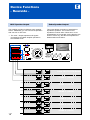
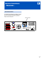
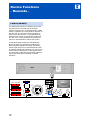
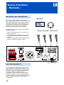
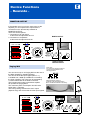
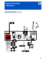
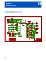
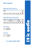
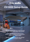
User manual
Mixer Amplifier MT-AMP 06
Tuner module
CD/MP3 module
… to make people listen
ic audio
Mixer Amplifier MT-AMP 06 CDT
Status 11/2006
MT-AMP 06 CDT
ic audio
Mixer Amplifier - Front -
Mixer Amplifier - Rear -
20060651
EN
2
Content
Preperation
Unpacking 5
ic audio
Device Functions
- Rear Side -
Safety Instructions 5
General Information 5
115V and 230V Mains Connection 15
Cooling 6
24V Battery Connection 15
Desktop Mounting 6
100V/8W Speaker Output 16
Aerial Connection 17
LINE OUT 18
Special Characteristics
Paging Microphone 7
Output Function 7
Common Function 7
Inputs 7
Outputs 7
LINE IN AUX19
Priorities 20
Input sensitivity MIC 1 20
Telephone Input 21
Chime 21
MONITOR OUTPUT 22
Paging Mic INPUT (12-pin) 22
Top view of all functions 23
Device Functions
-Front side-
LED - Display 9
ON/OFF -Switch 9
VU-Display 10
Microphone Input 10
Microphone Controller 11
LINE-Controller,
LINE-Select:
switch AUX/Tuner/CD-MP3/OFF 11
Further Information
Technical Specifications 25
Block Plugging Diagram 26
Index 27
Controller Bass and Treble 12
Controller Master 12
CD/MP3-PLAYER and Tuner 13
EN
3
Preperation
ic audio
Unpacking
Please note the unpacking instructions
- Unpacking
- Safety Instructions
- General Information
Safety Instructions
Please note the safety instructions before
connecting the MT-AMP 06
- Cooling
- Desktop Mounting
General Information
Instructions for the installation
Cooling
Please note the ventilation - cooling guidelines
Desktop Mounting
Please note the positioning of the Mixer Amplifier
EN
4
Preperation
ic audio
General Information
Unpacking
Please verify if the following parts were delivered:
! line cord
Safety instructions
! DO NOT run microphone cables near mains,
data, telephone or 100V line cables.
! DO NOT run 100V line cables near data,
telephone or other low voltage cables.
! DO NOT exceed 90% of the amplifiers output
power when using 100V line (speech only).
! DO NOT exceed 70% of the amplifiers output
power when using 100V line (high level
background music).
! DO NOT use re-entrant horn loudspeakers for
background music unless the loudspeaker has
been specifically designed for this purpose.
! ALWAYS use a balanced or floating low
impedance microphone terminating into a
balanced input on long microphone cable runs.
! ALWAYS use a mains grade double insulated
cable for the loudspeaker cable runs.
! ENSURE that all loudspeakers are in-phase.
! ENSURE that there are no short circuits on the
loudspeaker line before connecting to the
amplifier.
The wires of the main power line have the following
colours:
GREEN and YELLOW:
(E)
BLUE:
(N)
BROWN :
(L)
As the colours of the wires in the mains lead of this
apparatus may not correspond with the coloured
markings identifying the terminals in your plug
proceed as follows:
The wire which is coloured green and yellow must
be connected to the terminal which is marked by
the letter E or by the safety earth symbol or
coloured green and yellow. The wire which is
coloured blue must be connected to the terminal
which is marked with the letter N or coloured
black. The wire which is coloured brown must be
connected to the terminal which is marked with the
letter L or coloured red.
If a 13 Amp (B.S.1363) plug or any other type of
plug is used,a 5 Amp fuse must be fitted either in
the plug or at the distribution board.
5
EN
Preperation
ic audio
Cooling
The mixer amplifer pulls fresh air through the small
holes in the bottom sheet and pushes the exhaust
air through the long holes in the top sheet. Please
make sure that the internal space of the rack
system is cooling and you have a room maximum
temperature of 40°C..
We recommend to install a cooling system at the
rear site of the racksystem to support the transport
the exhaust air in the racksystem.
40°C
Exhaust air
Desktop Mounting
Fresh air
Put the Mixer Amplifier in a position with enough
space enough fresh air to minimise the heat in the
system.
Do not place the Mixer Amplifier close to of heat
sources or a heater.
Do not expose the Mixer Amplifier sunlight or
heavy dust.
EN
6
false
Special Characteristics
ic audio
Paging Microphone Functions
! 4 Microphone inputs with different Priorities
! 1 AUX
- Paging Microphone Functions
Output Function
- Output Function
- Common Function
! 6 Zones switchable and adjustable
! Music muting
! Pre-Amplifier Output
- Inputs
Common Function
- Outputs
!
!
!
!
115V and 230V Mains Connection
24V Battery Connection
Monitor Output
CD/MP3 - Tuner Mode
Inputs
!
!
!
!
AUX
4 Microphones
Paging Microphone Input (12-pin)
Telephone/Emergency Connection
Outputs
!
!
!
!
!
!
!
!
!
!
!
!
!
!
!
100V Entire Speakers
70V Entire Speakers
25V Entire Speakers
8 ohm Entire Speakers
100V Speakers of the first Zone
100V Speakers of the second Zone
100V Speakers of the third Zone
100V Speakers of the fourth Zone
100V Speakers of the fifth Zone
100V Speakers of the sixth Zone
LINE OUT
600ohm - Monitor
1V - Monitor
8ohm - Monitor
1Watt - Monitor
7
EN
Device Functions
- Front side -
ic audio
LED - Display
Display for the activation
ON/OFF - Switch
- LED - Display
Setting - up the Mixer-Amplifier
- On/Off - switch
Zoning
- Zoning
Choosing the Output Zone
- VU-Display
VU-Display
- Microphone Input MIC 1
Shows the saturation degree of the Mixer Amplifier
- Microphone Controller
Microphone Input MIC 1
- LINE - Controller
LINE - Select:
switch AUX/Tuner/CD-MP3/OFF
Connecting a microphone
Microphone Controller
- Controller Bass and Treble
Controller for the Microphone volume
- Controller Master
LINE-Controller
LINE-Select
switch AUX/Tuner/CD-MP3/OFF
Volume Control of the acoustic signal source
Bass and Treble Controller
Control of the high and deep frequency
CD/MP3-Player & Tuner
Using the optional items
Controller Master
Control of all Signals
EN
8
Device Functions
- Front side -
ic audio
LED - Display
LED - Display
The LED-Display shows the operational readiness
of the Mixer Amplifier.
ON/OFF - Switch
Zoning
With this switch you turn on the apparat.
Position I = apparat is on
Position 0 = apparat is off
After turning the machine on, the LED is shining
blue. Before turning the machine on, the Master
controller should be set to a low volume.
In addition to the normal 100V line output you can
select 6 Zones by using the push buttons on the
front panel.
ON/OFF - Switch
Zone Button No.6
Zone Button No.5
Zone Button No.4
Zone Button No.3
Zone Button No.2
Zone Button No.1
9
EN
Device Functions
- Frontside -
ic audio
VU - Display
The VU-Display shows the saturation degree of the
Mixer Amplifier. The green LED’s indicates the
level which can be run continously without any
interferences. The red LED is iluminated at the full
saturation degree only. This level is not appropriate
for enduring operation.
VU meter - Display: -25db, -18db, 10, 6, 0db.
Microphone Input
The first microphone MIC1 is prior to all others.
MIC1 being in use automatically gates all other
microphones. If music is hooked up to the system
while an announcement is being made, the gate
shuts of the music so that with the specific desktop
microphone the announcement signal can go
through. This setting will remain until the
announcement has ended.
Then then the music automatically fades back in.
EN
10
Microphone Input (6,3mm chinch)
Device Functions
- Frontside -
ic audio
Microphone Controller
Using this controller you can set the volume of the
microphones.
Microphone Controller
LINE - Select: switch AUX, Tuner, CD-MP3, OFF
LINE - Controller
You can activate connected signal soureces with
the LINE - Select switch.
The volume of the connected Signal Sources can
be adjusted by the LINE - Controller switch. This
could be a built-in CD-Player, a optional Tape Deck
or a built-in Tuner.
EN
11
LINE - Controller switch
LINE - Select switch
Device Functions
- Frontside -
ic audio
Bass and Treble Controller
Controller
Bass and Treble
By using this controller you can adjust the
reproduction of deep and high frequencies.
The bass control lifts or lowers frequencies near to
100Hz at 10dB. The treble-control has the same
effect on frequencies near to 10.000Hz.
Master Controller
The master control drives the volume of all signals
being processed by the amplifier.
Signals of the TEL/EMERgency input are excepted.
They can be adjusted at the Rearside of the Mixing
Amplifier.
Master Controller
EN
12
Device Functions
- Frontside -
ic audio
CD/MP3-Player and Tuner are optional items
6 7 8 9
CD Operation
1. Select CD mode with LINE select switch.
2. Press Power key on CD-Player
3. Load disc into player and Play starts
automatically
4. Press Pause key and the play will be
suspended.
Press Pause key to resume play.
5. Press the Next keys (6+7) to select tracks
6. Press the Random key, random appears in the
display and tracks will be played out of the
sequence.
7. Press the Repeat key one time and the current
track is repeated. When the key is pressed
twice the whole disc will be repeated. To cancel
these functions press the Repeat key again.
8. Programming the CD-Player in STOP mode:
(a) Press the Program key
(b) Use the Next- or Previous key to
select a track
(c) Press the Repeat key to memorise the
selected track in your program. Repeat
stages (b) and (c) to program a maximum
of 20 tracks.
(d) Press the Play key to start the program. The
program repeats itself until the CD-Player
is stopped.
1
2 3 4 5
1. CD display
2. Repeat key
3. Random key
4. Program key
5. CD Power ON/OFF key
6. Previous key
7. Next key
8. Play/Pause key
9. Stop/Eject key
7 8 9 10 11
Tuner Operation
For FM reception connect a dipole aerial using
75 W coaxial to the socket at the rear of the unit.
Connect the supplied antenna to the AM spring
loaded terminals.
1. Select TUNER mode with the LINE select switch.
2. Select AM or FM with the BAND key.
3. Use the UP/DOWN keys to set a frequency
manually or the Scan key to automatically
search for the desired station.
4. To program a station press the Memory key.
5. Press a memory key (M1 to M5) or Shift key and
Memory key (M6 to M10) to store a frequency.
1 2 3 4 5 6
1. M1 (Memory key)
2. M2 (Memory key)
3. M3 (Memory key)
4. M4 (Memory key)
5. M5 (Memory key)
6. Shift key
7. Band select key
8. Down key
9. Up key
10. Scan key
11. ME key
EN
13
Device Functions
- Rearside -
ic audio
115V and 230V Mains Connection
Selector to adapt the mains connection
24V Battery Supply
Connection to UPS
- 115V and 230V Mains Connection
- 24V Battery Connection
- 100V/8W Speaker Output
- Aerial Connection
- LINE OUT
100V/8ohm Speaker Output
Terminal for 100V/8ohm - speakers
Aerial Connection
Connection of FM an AM Antennas
LINE OUT
Connecting an additonal amplifier
- LINE IN AUX
LINE IN AUX
- Priorities
- Input sensitivity MIC 1
- Telephone Input
- Chime
Terminal for LINE IN devices
Priorities
Effects of different Priority Statuses
Input sensitivity MIC 1
Adjust the input sensitivity for MIC’s and LINE-Devices
- MONITOR OUTPUT
Telephone Input
- Paging Microfone (12-pin)
- Top view of all functions
Using the Tel. input for emergency announcements
Chime
Activating a attention signal preceding a call
MONITOR OUTPUT
Connection of monitor devices (for tracing)
Paging MIC
Connection of Paging Microfone (12-pin)
Top view of all functions
Diagram connected with all possible devices
EN
14
Device Functions
- Rearside -
ic audio
115V and 230V Mains Connection
Mains Selector
The amplifier is factory set at 230 V(AC) mains
voltage. The Mains Selector is at the rearside of
the Mixer Amplifier.
You can set the switch to 115V if neccessary by
pushing the slide switch from right to left. Please
disconnect the mains cable before changing the
voltage supply.
Ensure yourself that the device is set to the local
mains voltage before you connect it.
Mains Supply
20060651
24V-Battery Supply
You can also drive the device with 24V(AC).
This is useful in case your mains connection is
broken down and you can bypass this with an
uninteruptible power supply (UPS).
The device is then automatically driven by external
battery power, regardless to the position of the
ON/OFF-switch.
Electrical stability of the system is increased by
earthing the case.
20060651
24V-Battery Supply / UPS Connection
EN
15
Device Functions
- Rearside -
100V Speaker Output
The amplifier provides six different 100V speaker
Zones. Additionally you can connect the speakers
with one 25V or 70V Zone.
! The 100V - Output reproduces all signals
processed by the Mixer Amplifer operated in
the standard mode.
ic audio
8ohm Speaker Output
This output allows connection of standard low
impedance speakers. The minimum load
impedance must be 8ohm. When two or more
loudspeakers are connected, ensure that they are
wired in such a way, that the load impedance is
between 8ohm and 16ohm.
20060651
Line 100,70,25V,8ohm
ZONE 1 (100V)
ZONE 2 (100V)
ZONE 3 (100V)
ZONE 4 (100V)
ZONE 5 (100V)
ZONE 6 (100V)
EN
16
Device Functions
- Rearside -
ic audio
Aerial Connection
The MT-AMP 06 provides the possibility to connect
two antennas (FM and AM) at the rearside of the
gear. The connection can be done by the AMclamps oder the FM jacket.
Antenna connection
20060651
EN
17
Device Functions
- Rearside -
ic audio
LINE OUT
These standard RCA phono sockets provide a
mixed output suitable for connection of an
amplifier.
Please note: The connection of an power amplifier
is providing you an additional zone. This zone is
not adjustable (Music/Speech, Speech only). The
power for the 6 zones will remain at 240W.
Amplifier
20060651
EN
18
Device Functions
- Rearside -
ic audio
LINE IN (CD/AUX)
The equipment provides an auxiliary input which
may be used for connecting of other signal
sources such as a CD- or Cassette player. A slide
switch is located on the front panel for selection of
Aux and CD. The line level control operates on
each of the input sources. To operate select the
desired music source using the slide switch and
turn the "Line" control clockwise to increase the
volume or anticlockwise to reduce the volume.
The AUX/CD input sockets are standard RCA
phono sockets. Two sockets are supplied and
these are linked together internally. This allows
stereo signal source to be used without the need
to obtain a special lead. However you may wish to
check with the manufacturer of the signal source
to ensure that no damage will result if the left and
right output channels are working in parallel
operation.
Tape
20060651
EN
19
Device Functions
- Rearside -
ic audio
Microphone input with XLR-Jack
XLR-Input
Mic 1 input is either a balanced standard 1/4”
stereo jack on front panel or XLR on the rear panel
(with selectable phantom power). Mic1 input has
VOX priority which will be override Mic2-4 and
AUX (LINE) input signals but not the Telephone
input. Mic2-4 inputs are XLR with selectable
phantom power located on the rear panel.
The phantom power is factory set off and can be
enabled as follows:
1: SCREEN
2: HOT
3: COLD
2
1
3
Microphone input (MIC 1-4 with XLR-jack)
1. Remove power lead from the AC wall socket.
2. Remove top cover.
3. Locate the link pins (marked jump 1,2,3&4) on
the PCB behind each microphone XLR input
socket.
4. Connect shorting plug to the centre pin and ON
position to enable the Phantom power.
20060651
Input Sensitivity (MIC 1)
Input Sensitvity (MIC 1)
Two switches are loctated at the rear side of the
Mixer Amplifier. By changing the position of the
switches you can adjust the input sensitvity of the
Microphone INPUT 1. You can choose between
the factory settings for LINE-Devices or
microphones. If the switch is set in the position
VOX the microphone 1 will be activated and has
priority muting other microphones and music. This
setting is engaging the MIC 1 and the paging
microphones.
EN
20
Device Functions
- Rearside -
ic audio
Telephone Input
This input is for emergency announcements /
signals and is not effected by the Master Control.
The input level can be set by rotary control on the
rear panel.
The TEL input has the highest priority and will
override all other inputs. The volume can be
adjusted by the controller on the rear side.
The TEL input has the highest priority
and will override all other inputs.
The signal will be delivered
to all output zones!
~
~
~
~
GND
TelefonSystem
GND
Input for Emergency calls
20060651
Volume Controller
Emergency calls
Chime (Type: Siemens SAE 800)
Switching the manual muting terminals on the rear
panel will activate the chime function
(”DING-DONG” attention signal preceding a call).
The default volume of the chime is pre-set at the
factory and is adequate for most applications.
The sound of the chime (1-tone, 2-tone, 3-tone)
can be selected by jumper-settings on the circuit
board.
21
EN
Device Functions
- Rearside -
ic audio
MONITOR OUTPUT
If the speaker zone is not in the same room as the
amplifier you can supervise the output with the
connectors on the terminal strip marked as
MONITOR OUTPUT.
There are several options.
1. Connection of an ear phone
at the terminal output 600W and 1V.
2. Connection of a speakers
at the terminal output 8W and 1W.
MONITOR OUTPUT
20060651
Volume Controller
MONITOR OUTPUT
Paging MIC (12-pin)
You can connect up to 12 Paging MIC’s at the rear of
the Mixer Amplifier in parallel operation.
The amount of the NF-input-signal (INPUT -/+)
is suitable from -40dB up to 0dB and is exucted by
the input controller. The chime can be activated by
a contact transmitted to the GND connection.
The internal power supply of the Mixer Amplifer
will operate the paging MIC’s.
The maximum power consumption should not be
higher then 1,5 Ampere.
The Priority setting activates the 100 V output
(Speech Only) and will override all other input signals.
Please note:
For operating the paging microphones
you have to put the switches in the
following positions:
Adaptor (SUB-D 9 to clamp) for
connection of the paging microphones
M-E 01 and M-E 04 is included in the delivery.
20060651
EN
22
Device Functions
- Rearside -
ic audio
Top view of all functions
100V Line
Paging MIC
Microphone
FM Antenna
AM Antenna
20060651
MONITOR
ZONE 6
ZONE 5
~
ZONE 4
GND
~
~~
GND
Amplifier
Telephonesystem
ZONE 3
ZONE 2
ZONE 1
TUNER
CD
EN
23
Further
Information
ic audio
Technical Specifications
Containing all technical specifications
Block Plugging Diagram
- Technical Specifications
- Block Plugging Diagramm
- Index
EN
24
Circuit construction
Index
Content in alphabetical order
Further
Information
ic audio
Technical Specifications
Type
Mixer Amplifier
Modell
MT-AMP 06
AC 115V / 230V , 50 / 60Hz ± 10% selctable
DC 24V (Max 10% deviation)
360W
240W
SPEAKER OUTPUTS:
MUSIC/SPEECH: 8ohm, 25V, 70V, 100V selectable
LINE OUT: 600ohm, 1V
Mains Voltage
Supply
Battery Voltage
Output power max:
Rated power:
Outputs
Inputs
MOH OUTPUT: 8ohm 1 watt / 600ohm,1V balanced.
MIC 1: 250ohm, 1mV, symmetric with phantom power selectable,
to LINE switchable.
MIC 2: 250ohm, 1mV, symmetric with phantom power selectable.
MIC 3: 250ohm, 1mV, symmetric with phantom power selectable.
MIC 4: 250ohm, 1mV, symmetric with phantom power selectable.
AUX: 600mV, unbalanced
TEL : 0.1~1V,600ohm, adjustable, balanced
Frequency response
MIC1~MIC4: 60Hz ~ 15KHz ± 3dB
Total harmonic distortion
Signal to noise ratio
Less than1% at 1KHz, rated power
All VOLUME CONTROLS C.C.W. : 75dB below rated power
MIC1 ~ 4
: 60dB below rated power
TEL
: 70dB below rated power
LINE (AUX/CD) : 70dB below rated power
BASS : +/- 10dB at 100Hz
TREBLE: +/-10dB at 10KHz
MIC1~MIC4 volume control
LINE (AUX/Tuner/Cassette/CD) volume control
MASTER volume control
TEL input level control
MOH output level control
TONE controls (Bass,Treble)
Zone 1 , Zone 2, Zone 3, Zone 4, Zone 5, Zone 6 Buttons
AC 115V / 230V voltage selector switch
Tone controls
Controls
Indicators
AC power consumption
DC power consumption
Chime
Priority
Power indicator (LED),output level indicators (3 LEDS)
760 watts
Dimensions (H x W x D)
Weight
Colour
16A
1,-2,-3-stufiger Mehrklanggong.
PRIORITY LEVEL (Using for MIC1~4)
TEL / EMER MIC1 MIC2 MIC3 MIC4 AUX/CD
3
2
1
1
1
1
Desktop: 145x430x360mm
app. 17,7kg
Black
Optional Modules
CD/MP3 Module MT-06, Tuner Module MT-06
EN
25
Further
Information
Block Plugging Diagram
EN
26
ic audio
Further
Information
ic audio
INDEX
A
115 V and 230 V Power supply
M
Master Controller 12
Microphone Inputs 10
Microphone Controller 11
MONITOR OUTPUT 22
B Bass and Treble Controller 12
Battery Connection 15
Block Plugging Diagram 26
OON/OFF - switch 9
C CD-Player 13
Outputs 7
Chime 21
PPriorities 20
D Desktop-Mounting 6
I
K
S Safety instructions 5
Speaker Output 16
Inputs 7
Input sensitivity MIC 1 20
T Telephone Input 21
Technical Specifications 25
Top view of all functions 23
Tuner 13
Cooling 6
L LED-Display 9
LINE IN 19
LINE OUT 18
U
Unpacking 5
Z
Zoning 9
ic audio
www.ic-audio.com
EN
27
ic audio GmbH
Boehringerstraße 14a
68307 Mannheim /
Germany
Fon:+49(0)621/ 77096-0
Fax:+49(0)621/ 77096-26
www.ic-audio.com
Email: [email protected]
ic audio
… to make people listen